Page 1 :
CHAPTER 4, Brakes Wheels and, Tyres
Page 2 :
• Syllabus: Brake: its need and types:, Mechanical, hydraulic and pneumatic, brakes, Disc and drum type: their relative, merits, Brake adjustments and defects,, Power brakes, Wheels and Tyres: their, types; Tyre construction and specification;, Tyre wear and causes; Wheel balancing.
Page 3 :
Brake, The device used to stop any vehicle by, applying frictional forces., One of most important control components, of vehicle., They are required to stop vehicle within, smallest possible distance., This is done by converting kinetic energy of, vehicle into heat energy which is dissipated, into atmosphere.
Page 4 :
Vehicle is accelerated, , Brake Principle, &, Purpose of a, Brake, , Large amount of energy, still remain which is called, Kinetic Energy, , Tractive, resistance, Friction, , Energy supplied by the engine causes the vehicle speed to increase, , The existence of kinetic energy can be seen when a vehicle is moving, and neutral gear is selected. The car does not immediately stop;, instead it travels for a considerable distance before become stationary.
Page 5 :
Brake Principle 2, In order to drastically reduce the stopping distance of a vehicle ,, BRAKE SYSTEM is needed to convert the energy at a faster, rate., , CONVERT KINETIC ENERGY TO HEAT, ENERGY
Page 6 :
Brake Principle 3, The speed of energy conversion controls the Rate of, Deceleration, , Brake Force Padel, , Heat, , Kinetic Energy, , Road force at, driving wheel, Heat generation at the brake is obtained by rubbing a fixed pad or, shoe against a rotating object driven by the motion of the vehicle
Page 7 :
Brake Principle 4, The brake engineer has two challenges:, 1. Create enough deceleration to, car as quickly as the driver, without exceeding the drivers, level with regard to pedal effort, travel., , stop the, wishes,, comfort, or pedal, , 2. Manage the resulting heat energy so as, not to damage the brake system or the, rest of the vehicle., , An interesting observation is that a typical car of this size has an, engine with about 90-105 KW (120-140 HP). This means that the, brakes have to deal with about TWICE THE POWER of what the, engine puts out.
Page 8 :
Brake Principle 5, , Since the kinetic energy of a moving vehicle is a function of the square of the speed,, the speed from which you wish to stop a vehicle is much more important than the, mass of the vehicle. When selecting a brake system the performance of the, powertrain must be taken into consideration.
Page 9 :
Brake Principle 6, Weight transfer increases the load on the front wheels while, the load on the rear wheels is reduced.
Page 10 :
Brake Principle 7, When the limit is reached…….the wheel starts to skid, At that moment extra applied at brake pad is, useless. No benefit is reducing the stopping, distance, On icy surface …………light pressure can lock-up, the brake system, Important information: adhesion between the tyre & road, is the main factor that control the minimum stopping, distance, Road adhesion is affected by, 1. type of road surface, 2. Condition of road surface, 3. Design of tread & composition of, tread material and depth of tread
Page 11 :
Braking system, Brake is a device used for slowing ,stopping & controlling the, vehicle., Braking operation based on kinetic energy of vehicle is, to converting into heat, which dissipated into atmosphere., While driving the vehicle, torque of the engine produces, The tractive effort due to periphery of driving vehicle., When the brakes are applied it produces negative tractive, effort on wheel., While, this help to slow down an vehicle
Page 12 :
Main functions of braking system, To stop the vehicle, safely in shortest, possible distance in, case of emergency., To control the vehicle, when it is descending, along the hills, To keep the vehicle in, desired position after, bringing in at rest
Page 13 :
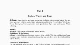
Braking Requirements, 1. Brakes must be strong enough to stop vehicle within a, minimum distance in an emergency., 2. Brakes must have good antifade characteristics i.e., their effectiveness should not decrease with, prolonged application. This requirement demands, cooling of brakes should be very efficient., Wheel brake must meet the following requirements, 1., 2., 3., 4., 5., 6., 7., , Uniform effectiveness, Smooth, graduated response, Resistance to contamination & corrosion, Extreme reliability, Durability, Resistance to wear, Ease of maintenance
Page 14 :
Generally all motors vehicle must be equipped with at least two mutually independent, brake systems., 1. Service Brake System – primarily serve to reduce vehicle speed, 2. Emergency brake system – Used to stop a vehicle in the event of a malfunction, 3. Parking brake system – to prevent unintentional rolling of a stationary vehicle ( Hand, Brake)
Page 15 :
Types, • The brakes of an automobile are classified, according to as :1. Purpose, 2. Location, 3. Construction, 4. Method of actuation, 5. Extra braking effort
Page 17 :
General Brake System, , Types of Brakes, 1. Drum Brake, 2. Disc Brake
Page 18 :
Mechanical Braking System, , Classification, Mechanical Braking System, brakes are available in following construction, 1.Drum type, 2.Disc type, Drum type Brake, There are generally of two types, Internal expanding drum brake., External expanding drum brake.
Page 19 :
Internal Expanding Brake, Drum, , Construction., In Internal Expanding Drum, Brake consist of leading shoe,, anchor, adjustor, Heel of shoe,, trailing shoe, brake retracting, spring brake shoe, brake shoe, toe, shoe etc., In internal expansion braking, system brake liners are expands, internally, Its consist of stationary plate, two, shoes hinged at anchor pins, and, cam system to expand the shoe, and a retracting spring.
Page 20 :
Drum Brakes
Page 22 :
Working system of internal, braking system, , Internal expanding braking, system consist of brake linings are, fixed at outsides when brakes are, applied the cam is turned, the, shoe with brake lining are forced, against the Drum., This Causes brake lining creates, friction between the rotating drum, and expanding shoes., This force of friction opposes the, rotating drum, thereby will leads, to slowing down the vehicle., When brake is released Retracting, springs brings the shoe back, towards its original position.
Page 23 :
External contracting brake drum, , Construction, IN external contracting brake drum has brake drum is used for only parking, purpose .this system consist of Drum, brake & lining, operating lever with, adjusting lever and push rod with returning spring., External braking system is model braking system used to operate in floor mills,, various types of electrical components. the following various types of parts is, applied on brake drum..
Page 24 :
WORKING OF EXTERNAL CONTRACTING, BRAKE DRUM, The working system of external, braking system, when push rod is, operated by hand or foot operated, lever, then the lined brake drum is, fitted around the drum is tightened, to lock or slow down the drum., When the brake is released the, return springs bring the band brake, back to its initial position., The system remains air opened;, therefore dirt is being accumulated, between the rubbing surfaces, which, reduces the efficiency…
Page 25 :
Disc Brakes, • A disc brake consists of a cast iron disc bolted, to wheel hub and stationary housing called, caliper. Calliper is connected to some, stationary part of vehicle like axle., • When brakes are applied, piston move friction, pads into contact with disc, applying equal, and opposite force on disc On releasing, brakes, the rubber sealing rings act as return, springs and retract piston and friction pads, away from disc.
Page 26 :
Disc Type Brake, , CONSTRUCTION, DISC Brake consist of cat iron disc bolted to the wheel hub and an, stationary housing called “caliper”. The caliper is connected with some, stationary part of position of vehicle, like stub or axle on of wheel of, connecting rod ., The piston rod is connected in between which has friction pad is being held, by an piston pins, springs etc.
Page 27 :
Working, of, Disc, brake, The brakes are operated when friction is being, created on friction pads by forced applying on it, against the disc .the forces created on its is, hydraulic pressure from master cylinder, thereby, an engaging the braking system., When the hydraulic braking pressure is applied on, piston will engaged an released bar due to, pressure., When pressure is released piston will regain its, original position. Here friction pad works on main, fundamental working process., “CALIPER “ is added on system to balanced two, calipers by diagrammatically opposite to each to, other. In this way braking torque is reduced., , Advantages of Disc Brake, Better heat dissipation as braking torque on surface of exposed air., Adjustment of pads is automatic, Renewal of pad is quick and easy., , Disadvantages of Disc Brake., In comparison of brake drum of similar capacity, rate pad wear is more., The HAND BRAKE MECHANISM IS NOT SO CONVINENT.
Page 28 :
Disc Brakes
Page 31 :
Mechanical Brakes, • Mechanical brakes are assemblies consisting of mechanical elements for, the slowing or stopping of vehicle. They use levers or linkages to transmit, force from one point to another., • There are several types of mechanical brakes. Band brakes, the simplest, brake configuration, have a metal band lined with heat and wear resistant, friction material. Drum brakes, which are commonly used on automobile, rear wheels work when shoes press against a spinning surface called a, drum. Disc breaks are constructed of brake pads, a caliper, and a rotor., During operation, the brake pads are squeezed against the rotor. Cone, brakes are made with a cup and a cone, which is lined with heat and wear, resistant material. During actuation, the cone is pressed against the, mating cup surface.
Page 34 :
Hydraulic Brakes, • The hydraulic brake is an arrangement, of braking mechanism which uses brake fluid, specially ethylene glycol to transfer pressure from, the controlling unit to the actual brake, mechanism of the vehicle., • Parts of hydraulic brakes:1., 2., 3., 4., , Brake Pedal, Push rod, Master cylinder assembly, Wheel cylinder
Page 35 :
HYDRAULIC BRAKING SYSYTEM, , construction, hydraulic braking system is mainly confined with “brake fluid” this fluid consist, of Alcohol,castor oil & glycerin.hydraulic braking system has following, components., master cylinder,brake pedal,wheel cylinder,brake drum,retracting spring,brake, shoe etc.
Page 36 :
Working System, The brake pedal is connected to the master cylinder, by means of piston for application of brake driver, presses the brake pedal, which moves the master, cylinder., In master cylinder pressure is instantly transferred to, all four wheels. The brakes shoe moves against the, brake drum to apply brakes., When driver releases the brake pedal, the master, cylinder piston returns to its original position due to, return springs, dropping fluid pressure. Brake shoe, retracting spring pulls the brake shoe from drum to, their original position & brakes are released., ROLE OF MASTER CYLINDER:, TO BUILD THE hydraulic pressure required to, operate the system., To bleed or force air out of brake line & wheel, cylinder., A to act reservoir to maintain a constant volume of, fluid in system, ADVANTAGES OF HYDRAULIC BRAKE, , simple in construction :Mechanical joints, linkages &, cam are eliminated., Equal braking system: the brake fluid must exists, equal pressure., Disadvantages of Hydraulic Brake, Fails whole system at one time: if there is leakages in, system, all four brakes are fail at one time due to loss, of fluid pressure. This difficulty can be eliminated with, use of tendum master cylinder
Page 39 :
Air brake system
Page 41 :
CONSTRUCTON, Pneumatic brakes are operated by means of, Air pressure engine to air and stores in air, reservoir. the compressed air enters in wheel, cylinder to push diaphragm, The pneumatic braking system consists as :, •, , Air compressor, unloader valve, reservoir,, brake valve, brake chamber ,quick release, valve, Relay valve etc.
Page 42 :
• The Automatic Slack Adjuster (ASA) is a vital, part of the foundation brake. It acts as a lever,, forming the connection between the actuator, and the camshaft. The function of the ASA is, to compensate for wear in both brake lining, and brake drum while maintaining a constant, stroke of the actuator.
Page 43 :
Pneumatic Braking System
Page 44 :
Working of Pneumatic, Braking System, , Air Compresor, Its composes of generally Build the, air pressure by driven of engine., , UNLOADER VALVE:, ITS IS DEVICE MAINTAIN CONSTANT, PRESSURE IN RESERVOIR.the excess of, pressure is safely removed., , Reservoir:, it’s a tank in which high, pressure air is stored, , Brake Valve:, its is located between air, reservoir and brake cylinder, , RELAY VALVE:, IT IS VALVE KEPT IN BETWEEN, BRAKE CHAMBER & AIR CHAMBER FOR, CONTROLLING THE AIR CHAMBER
Page 45 :
Power Brakes, • These are the brakes in which power of engine or, battery is used to enhance the braking effort., • These are of four types:- Vacuum Brakes, Air, Brakes, Hydraulic Booster Brake and ElectroHydraulic Booster brake., 1. Vacuum Brakes:- Vacuum brake system is, controlled through a brake pipe connecting a, brake valve in the driver's cab with braking, equipment on every vehicle. The operation of, the brake equipment on each vehicle depends, on the condition of a vacuum created in the, pipe by an ejector or exhauster.
Page 46 :
Servo Brake System, 1. Servo Mechanism:- A servomechanism,, or servo, is an automatic device that uses, error-sensing negative feedback to correct the, performance of a mechanism. It applies only, to systems where the feedback or errorcorrection signals help control mechanical, position, speed or other parameters. It is an, electronically controlled mechanical or, hydraulic device permitting a large action or, strong forces to be controlled by a small, electrical signal.
Page 48 :
The functions of wheel in the Automotive, vehicle are,, 1.To observe the impact forces of the road, surface and to bear the vehicle load., 2.Transfers the rotational movement of the, axles to Tyres., 3.Absorbs and transfers the braking and, Accelerating forces as well as cornering, forces., 4.Dissipates the braking heat to the, atmosphere and, 5.Acts as a seal in case of tubeless tyres.
Page 49 :
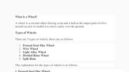
Types of Wheels:, 1) Disc wheels: It consists of wheel disc also called as wheel, nave and the Rim. The wheel disc connects the Rim with, the Hub and the Rim holds the tyre., 2) Cast or forged wheels: Cast disc wheel consists of a ready, cast partor a cast blank that is then forged. The wheels are, then cut to shape. The cast wheels are made from lightalloy, malleable cast iron and cast steel wheels. The usages, of cast steel wheels are limited due to its heavy weight., Cast and forged wheels are more expensive than the, welded steel disc wheels but they are preferred due to its, high stability and precisely machinable quality.
Page 51 :
• Multi-piece wheels:, • In the case of multi-piece system the Rim parts are bolted, to the wheelrim. If the wheel rim remains on the hub it is, easier to change thewheel but the disadvantages are its, heavy weight and highmanufacturing cost., • Wheel weight and load bearing capacity:, • The dead weight of the wheel should be as low as possible, and at thesame time it should have high load bearing, capacity in order achievelow unsprung masses. The, advantage of light weight wheels are, • -Improved vibration Characteristics-Sensitive suspension, response-Low fuel consumption and-Higher pay load., • By changing over from steel to alloy rims approximately 200, kg weightcan be saved on a three axle semitrailer tractor.
Page 52 :
• Rim Designs:, Rims are having the functions of holding the tyre as well, as sealingfunction in case of tubeless tyres. They are, classified as follow based ontheir construction., -Drop centre rims, -Flat base rims, -Slanted taper bead seat rims, -Taper bead seat rim, • Drop centre rims and Taper bead seat rims are made up, of one piece,slanted taper bead seat rims are multi, piece rims. A raised part allaround the bead seat in case, of Taper bead and Drop centre rims,improves the, fixation of the tyres.
Page 53 :
Drop centre rims:, , • These are one piece rims used in light, commercial vehicles and cars. The raise, in the bead seat is 5 degree. They are, not suitable for highload bearing, capacities due to their design and being, used incommercial vans and mini buses.
Page 55 :
• Taper bead seat rims:, • In order to exploit the advantages of tubeless, tyres also on heavy trucks, the taper bead seat, rims with drop centres were developed. The bead, seat rises on these rims by approximately 15, degrees. Taper bead seat rims are one piece and, having low weight with good load bearing, capacities. In this design wide rims are used to fit, wider tyres and hence it is very suitable for heavy, loads.
Page 57 :
•, •, •, •, , Illustration example: 9.00 x 22.5, Rim width in inches = 9.00, One piece = x, Rim diameter in inches = 22.5
Page 58 :
• Slanted taper bead seat rims:, • Slanted taper bead seat rims are multi piece rims, for commercial vehicles with inner tubes. The rise in, the bead seat is around 5 degree. The tyre is held, on one side by removable combination or side and, fastening ring. In such type of rim system, it is very, easy to change the tyres but it does not have good, running characteristics as compared to one piece, system., • Illustration example: 8.50 – 20Rim width in inches:, 8.50Multi piece = “–“Rim diameter in inches = 20.
Page 59 :
• Trilex, Tublex and Unilex Rims:, • The three piece wheel system as shown, in the sketch below allow easy tyre, mounting, but they do not seal the rim,, hence they need an inner tube.
Page 61 :
• It normally comes with higher dead weight, due to separate rim part sand wheel rim., These rims are used very rarely now days, where there are no service stations are, available. Tublex and Unilex rims are also, suitable for tubeless tyres but here the rims, are not split axially (likein case of Trilex) but, they have removable rim flange and an, additional ring as shown in the sketch below.
Page 63 :
• Function:
Page 64 :
• Wheel Weight and Load Bearing Capacity:, • All wheels are assessed mainly by the two criteria 1) The wheel, weightand 2) Load bearing capacity. Light wheels with high load, bearingvalues increases the pay load of the any kind of vehicles., • Specific Load Bearing Capacity:, • The usage extent of the wheel or Rim construction is referred, bySpecific load bearing capacity. It is the ratio of load bearing, capacity orultimate load (in KG) to the Dead weight of the wheel, in KG and henceit is a direct measure of efficiency., • Specific Load-bearing capacity “t spec” =Load capacity of, wheel /Dead weight of wheel in Kg., • The higher the value of the specific load bearing capacity , the, moreload the wheel can bear In relation to its dead weight and, higher payloads can be used. At the same time the rolling, properties are
Page 65 :
• improved., • The specific load-Bearing capacity can be, increased by choosing the light alloy and, aluminium wheels by saving more weights.(Fig, below), • For Super wide tyres with weight of rims and, tyre put together 246 and304 kg, the specific, load bearing capacity and mean value of load, bearing capacity is shown graphically as below.
Page 67 :
Wheels & Tyre, Wire wheels
Page 68 :
Disc wheel
Page 69 :
Light alloy cast or forged wheel
Page 72 :
STUDY OF WHEEL BALANCING, Tire balance, also referred to as tire unbalance or imbalance,, describes the distribution of mass within an automobile tire, or the wheel to which it is attached. When the tire rotates,, asymmetries of mass cause the wheel to wobble, which can, cause ride disturbances, usually vertical and lateral, vibrations. It can also result in a wobbling of the steering, wheel. The ride disturbance, due to unbalance, usually, increases with speed. Vehicle suspensions can become, excited by tire unbalance forces when the speed of the, wheel reaches a point that its rotating frequency equals the, suspension’s resonant frequency.
Page 73 :
CONTINUE…., • Tires are inspected in factories and repair shops by two, methods: static balancers and dynamic balancers. Tires, with high unbalance forces are downgraded or rejected., When tires are fitted to wheels at the point of sale, they, are measured again, and correction weights are applied to, counteract the combined effect of the tire and wheel, unbalance. After sale, tires may be rebalanced if driver, perceives excessive vibration
Page 74 :
Static Balance, • Static balance can be measured by a static, balancing machine where the tire is placed, in its vertical axis on a non-rotating spindle, tool. The spot on the tire with the greatest, mass is acted upon by gravity to deflect the, tooling downward. The amount of, deflection indicates the magnitude of the, unbalance. The angle of the deflection, indicates the angular location of the, unbalance. In tire manufacturing factories, static balancers operate by use of sensors, mounted to the spindle assembly.
Page 75 :
CONTINUE…., • . In tire retail shops static balancers are most usually nonrotating bubble balancers, where the magnitude and angle, of the unbalance is observed by looking at the center bubble, in an oil-filled glass sighting gauge. While some very small, shops which lack specialized machines still do this process,, they have been largely replaced in larger shops with, machines.
Page 76 :
Dynamic balance:, • Dynamic balance describes the forces generated by, asymmetric mass distribution when the tire is rotated,, usually at a high speed. In the tire factory the tire is, mounted on a balancing machine test wheel, the assembly, is accelerated up to a speed of 300 RPM or higher, and, sensors measure the forces of unbalance as the tire rotates., These forces are resolved into static and couple values for, the inner and outer planes of the wheel, and compared to, the unbalance tolerance (the maximum allowable, manufacturing limits)
Page 77 :
CONTINUE…., If the tire is not checked, it has the potential to wobble and, perform poorly. In tire retail shops tire/wheel assemblies, are checked on a spin-balancer, which determines the, amount and angle of unbalance. Balance weights are then, fitted to the outer and inner flanges of the wheel. Dynamic, balance is better (it is more comprehensive) than static, balance alone, because both couple and static forces are, measured and corrected.
Page 78 :
CONTINUE…., • The dynamic balance can only be conducted if the driver, comes to garage and has the garage check for imbalances., With the increased use of electronics, the unbalance or, imbalance condition might be estimated by electronics in, real-time and independent of the driver's detection, capability. Recently, a SAE paper did the exactly same:, using sensors such as the ABS wheel speed sensors for a, brake control module to detect an imbalanced tire or tires, in real-time.
Page 79 :
The physics of dynamic balance, • Physics of tire imbalance, • Mathematically, the moment of inertia of the wheel is a, tensor. That is, to a first approximation (neglecting, deformations due to its elasticity) the wheel and axle, assembly are a rigid rotor to which the engine and brakes, apply a torque vector aligned with the axle. If that torque, vector is not aligned with the principal axis of the moment, of inertia, the resultant angular acceleration will be in a, different direction from the applied torque. Whenever a, rotor is forced to rotate about an axis that is not a, principal axis, an external torque is needed.
Page 80 :
• This is not a torque about the rotation axis (as in a driving, or braking torque), but is a torque perpendicular to that, direction. If the rotor is suspended by bearings, this torque, is created by reaction forces in the bearings (acting, perpendicular to the shaft). These reaction forces turn with, the shaft as the rotor turns, at every point producing, exactly the torque needed to keep the wheel rotating about, the non-principal axis. These reaction forces can excite the, structure to which they are attached. In the case of a car,, the suspension elements can vibrate giving an, uncomfortable feel to the car occupants.
Page 81 :
• In practical terms, the wheel will wobble. Automotive, technicians reduce the wobble to an acceptable level when, balancing the wheel by adding small weights to the inner, and outer wheel rims. Balancing is not to be confused with, wheel alignment.
Page 82 :
Balancing machine, A balancing machine is a measuring tool used for balancing, rotating machine parts such as rotors for electric motors,, fans, turbines, disc brakes, disc drives, propellers and, pumps. The machine usually consists of two rigid pedestals,, with suspension and bearings on top supporting a, mounting platform. The unit under test is bolted to the, platform and is rotated either with a belt-, air-, or enddrive. As the part is rotated, the vibration in the, suspension is detected with sensors and that information is, used to determine the amount of unbalance in the part., Along with phase information, the machine can determine, how much and where to add weights to balance the part., •
Page 83 :
Photo of wheel balancing machine
Page 84 :
Result of wheel unbalancing
Page 85 :
Specifications…., •, •, •, •, •, •, •, , Rim Width, Rim Diameter, Max. Wheel Diameter, Max. Wheel Width, Max. Wheel Weight, Power Supply, Gross Weight, , 1.5 – 20 Inch, 10 – 30 Inch, 1067 mm, 530 mm, 75 kg, 240 Volt, 133 kg
Page 86 :
Machine Features:, , • • Easy Auto Select 2 function, • • Bright & Easy to read digital display, • • Auto sense sonar device for automatic detection of rim, data, • • Automatic Megastick for unlimited weight positions, • • Automatic start of the machine by closing the wheel, guard, • • Automatic stop into the right-hand correction position, • • Optimisation program to compensate the unbalance of, tyre and rim, • • Durable weight tray with ample storage for wheel, weights
Page 87 :
PROCESS OF WHEEL BALANCING:-, , Remove the wheel from the vehicle., Fix wheel on the wheel balancing machine with the help of, zinc cones, as shown in above figure., Switch on power supply, UPS and the wheel balancing, machine., Press start button and give little support initial rotation, to the wheel by hand., Now wheel will start rotating with a speed of 300 rpm, aprrox., Now press the brake pad of machine which near the base, of the machine.
Page 88 :
Monitor will show the result of the unbalance weight and, will show the required weight of either sides, as shown in, figure above:, Now rotate the tire manually for adjusting the weight, requiring positioning., Now fix the required weights on inner and outer flanges., Wheel is balanced now.
Page 90 :
Terminology, , , , , , , , , , , Steel Wheels – A very popular, design of wheel. Very strong, and cheap to produce., Alloy Wheels – Attractive and, light weight, but can be difficult, to clean., Spoked Wheels – Used on, older sports vehicles, but, cannot be fitted with tubeless, tyres., Divided rims – the rims are, made in two halves which are, bolted together, the rims must, never be separated while the, tyre is inflated., Split rims – the tyre is held in, place by a large circlip, do not, remove the tyre unless you, have been properly trained, , , , , , , , , , , , , , Radial Ply Tyre – the main, plies of the tyre run at 90, degrees from one bead to the, other., Cross Ply Tyre – the main, plies of the tyre run at 45, degrees from one bead to the, other., Plies – Layers of strong fabric, which are built up to give the, tyre its strength and shape, Bead – loops of steel which, are the anchorage point for the, plies., Tread – this provides the grip, with the road surface, the, pattern assists in clearing any, water away, Side Wall – this connects the, beads to the tread of the tyre.
Page 91 :
Wheel - Basics, Most standard wheels are made of steel., Some vehicles are fitted with alloy, wheels that are made of, magnesium or aluminium., The rim holds the tyre., The well of the wheel allows the, tyre to be removed and refitted, , Rim, , The centre section is, welded to the rim., The pilot bore fits to the hub., Centre mounting section, Next >
Page 92 :
Valve Stems and Cores –, Three functions – It retains the air, it, allows inflation and deflation., , Valve core, , The rubber stem of the valve is, pulled into the wheel., , Valve stem, , Seat, washer, , The valve core contains a, spring loaded air valve insert., , The valve core also has a sealing, washer and a seat washer., The valve cap keeps out, dust and helps keep air in., , Sealing, washer, , Tyre pressures must only be checked and, adjusted when the tyre is cold, , Valve caps, , Next >
Page 93 :
Wheel Fixings, Wheel studs and nuts attach the, wheel to the hub., , Taper, , The wheel studs press through, the hub or axle flange., The taper on the wheel nuts, secures and centres the wheel., Wheel studs usually have a, right-hand thread., If it is a left-hand thread, it can be, marked with “L”., Metric threads can be marked with “M”, or METRIC., , Wheel mounting, Hub flange, Next >
Page 94 :
Wheel Nut Torque, Correct torque of wheel fixing is, vital for all vehicles, and nearly, all require the use of a, torque wrench., Excessive torque can lead to, wheel or hub distortion, causing, runout and vibration., Low torque may allow wheel, nuts to work loose and wheels, to come off., Nuts should be tightened in a, diagonal pattern., , Torque, wrench
Page 95 :
Wheel Sizes
Page 96 :
Tyres (Introduction), , , , , , , , , Basis Functions, The tyre acts as the primary suspension,, cushioning the vehicle from the effects of a, rough surface., It also provides frictional contact with the road, surface., This allows the driving wheels to move the, vehicle., The front tyres allows the wheels to steer ., The tyres allow the brakes to slow or stop the, vehicle
Page 97 :
Pneumatic Tyres, , , , , , , , The tyre is a flexible casing, which contains air., Tyres are manufactured from reinforced synthetic, rubber., The tyre is made from an inner layer of fabric plies,, which are wrapped around bead wires at the inner, edges., The bead wires hold the tyre in position on the wheel, rim., The fabric plies are coated with rubber, which is moulded, to form the side walls and tread of the tyre. Behind the, tread is a reinforcing band, usually made of, steel,rayon,or glass fibre. Modern tyres are mostly, tubeless, so they have a thin layer of rubber coating, inside to act as a seal.
Page 98 :
Tyre Construction, • Cross – ply tyres are not used, on any mass produced modern, cars. However, the, construction details are useful, to show how tyre technology, has developed., • Several textile plies are laid, across each other, running, from bead to bead in alternate, directions., • The number of plies depends, on the size of the tyre and the, load it has to carry., • The same number of plies is, used on the crown and the, sidewalls.
Page 99 :
Tyre Construction, • Radial – Ply tyres consist of a, carcass ply formed by textile, arcs running from one bead to, the other., • Each ply which is laid in an arc, at an angle of 90 degrees to, the direction the tyre rolls., • At the top of the tyre crown, (under the tread), there is a, belt made up of several plies, reinforced with metal wire, laid, on top of the carcass ply., • These crown plies, laid one on, top of the other, overlap at an, angle determined by the type, of the tyre.
Page 100 :
Tyre Specifications, , P 205/55 V R 16, TYPE, P - PASSENGER, T - TEMPORARY, LT - LIGHT TRUCK, C - COMMERCIAL, , RIM DIAMETER, (INCHES) 13, 14 ETC, , ASPECT RATIO, (HEIGHT/WIDTH %), 55, 60, 65 70 ETC, , WIDTH, (MILLIMETERS), 145-315, , TYPE, B - BIAS-BELTED, D - DIAGONAL BIAS, R - RADIAL, , SPEED RATING, B (31 MPH) V (150 MPH) Z (OVER 150 MPH), Next >
Page 101 :
Special Service Tyre, This is a space-saver spare tyre., Used to replace flat tyre., It is not used for rotation, (swapping)., It uses a special wheel., Speed and pressure, restrictions apply., It has no hub caps or wheel covers., Next >
Page 102 :
• Remember the tyre tread depth must be not less than 1.6mm over the, central three-quarters of the tyre and must go all the way round the, circumference in an continuous unbroken band with no bald patches, anywhere on the tyre tread., • If radial and crossply tyres are fitted to the same vehicle, the radial-ply, tyres must only be fitted to the rear., • Cross-ply and radial ply tyres must never be fitted to the same axle., • Tyre pressures must be set to the manufactures recommendations, • The tread and side wall must be free from large cuts, abrasions or, bubbles
Page 103 :
Balance, Wheel imbalance causes wheel, tramp, or hop, makes the tyre, vibrate up and down., Centrifugal forces try to throw, heavy areas outward when the, wheel is spinning., , Weight must be evenly distributed, around the axis of rotation., Imbalance can be rectified in one of two, ways by Static Balancing (stationary), or Dynamic Balancing (spinning).
Page 104 :
Rotation, A system of rotation is used to even out tyre, wear and reduce the need for re-balancing., , (a), , (b), , (c), , (d), , (a) 4-wheel bias (cross-ply) tyre rotation., (b) 5-wheel rotation (including spare)., Radial tyres must be kept on the same, side of the car., (c) 4-wheel radial tyre rotation., (d) 5-wheel radials (including spare)., Care must be taken with spare as some, modern tyres are directional.
Page 105 :
Thank You, ?
Page 106 :
Causes, behind the, Uneven, Tire Wear
Page 107 :
Finding out a new, tire for the car often, comes as a surprise.
Page 108 :
Tires of the car need a, frequent replacement, for below reasons:, Driving too speed, , Drive like a crazy, Mash the accelerator, Slam on the brakes
Page 109 :
Uneven tire wear, indicates the, constant wearing, away tires.
Page 110 :
Premature or uneven, tires wear caused for, several factors:, Faulty tire pressure, Loose suspension components, Misaligned wheels, Leaking steering parts
Page 111 :
Uneven tire wear can, be caused for belowdefined reasons.
Page 112 :
Damaged steering, components
Page 113 :
When the steering, components of the, car are damaged, it, will indicate:, Loose ball joint, , Worn out tie rod end, Excessive moving rack and, pinion
Page 114 :
As a result, it will, scrub the tires and, excess friction cause, tire tread wear.
Page 115 :
Wrong tire pressure
Page 116 :
Over-inflated tires can, wear out the center of, the tire tread faster.
Page 117 :
Under-inflated tires, can wear out the, inner and outer tire, shoulder quickly.
Page 118 :
Loose suspension parts
Page 119 :
Worn out suspension, parts of the car indicate, several signs:, Leaking strut, , Broken coil spring, Worn out shock
Page 120 :
When the suspension, parts are damaged, it, will cause uneven tire, wear.
Page 121 :
Improper wheel alignment
Page 122 :
Wheel alignment of, the car plays a vital, role in tire wear.
Page 123 :
Incorrect angled, tires will cause, excessive tire wear, and affect the, wheels.
Page 124 :
Prevent tire wear
Page 125 :
Through routine, maintenance one can, prevent tire wear. Such, as:, Tire pressure adjustments, Regular car tire inspection, , Four-wheel alignments
Page 126 :
Affected tires need, rotation on a regular, interval for less, susceptible wear.
Page 127 :
Replace the tires of the, car by a reputed and, qualified mechanic.