Notes of TY MECH, Automobile Engineering Ch 2 Steering and Suspension Systems_.pdf - Study Material
Page 1 :
UNIT 2, , STEERING AND SUSPENSION, SYSTEMS
Page 2 :
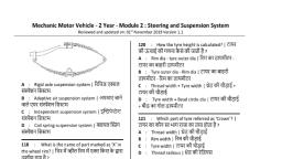
SYLLABUS, •, , •, , Steering system; Principle of steering,, Centre point steering, Steering linkages,, Steering geometry and wheel alignment,, power steering., Suspension system: its need and types,, Independent suspension, coil and leaf, springs, Suspension systems for multi-axle, vehicles, troubleshooting and remedies.
Page 3 :
Introduction of steering system, •, , •, , Steering is the collection of components, linkages,, etc. which allow a vessel (ship, boat) or vehicle, (car, motorcycle, and bicycle) to follow the, desired course., The most conventional steering arrangement is to, turn the front wheels using a hand–operated, steering wheel which is positioned in front of the, driver, via the steering column, which may contain, universal joints (which may also be part of the, collapsible steering column design), to allow it to, deviate somewhat from a straight line.
Page 5 :
Basic Principles, •, , •, , The steering system, along with the suspension, system, allows the driver to safely and easily, control the vehicle’s direction while driving. To, accomplish these goals the steering system works, with components of the suspension to provide for, the turning movement of the wheels., In addition to connecting the driver to the wheels,, the steering system also provides feedback to the, driver from the front tires. This feedback, called, road feel, is used by the driver to determine how, the vehicle is handling.
Page 6 :
The Steering System, •, , The steering system consists of the, components that allow the driver to turn the, front wheels of the vehicle, and for a few, vehicles, provides for a limited amount of, steering by the rear wheels. The overall, function of the steering system has not, changed much since the earliest days of the, automobile.
Page 7 :
Functions of the Steering System, •, , •, , Primary function: to achieve angular motion of the front wheels, to negotiate a turn. This is achieved through linkages & steering, gear which convert the rotary motion of the steering wheel into, angular motion of the front road wheels., Secondary functions are:, 1. Provide directional stability of the vehicle when going straight, ahead., 2. Provide perfect steering condition. i.e. perfect rolling of all, wheels at all times., 3. Facilitate straight ahead recovery after completing a turn., 4. To minimize tyre wear., 5. Absorb most of the road shocks going to the steering wheel.
Page 8 :
Requirements of a good steering system, 1. Steering system should be very accurate & easy to, handle., 2. Effort required to steer should be minimal & must, not be tiresome to the driver., 3. Steering mechanism should provide directional, stability., 4. The vehicle should have a tendency to return to its, straight ahead position after turning., 5. High rigidity., 6. Low friction resulting in high efficiency.
Page 10 :
General arrangement of steering system
Page 13 :
Steering Parts, •, •, , •, •, , •, •, , Steering wheel, Steering column or steering outer tube, Steering shaft, Steering gear box, Drop arm, Steering linkage
Page 14 :
STEERING SYSTEMS, 1. Manual steering system – relies solely on, the driver to provide steering force, 2. Power assist (power steering) – uses, hydraulic or electric power to help the, driver apply steering force.
Page 15 :
STEERING SYSTEM – COMPONENTS
Page 16 :
Steering wheel: used by the driver to rotate a, steering shaft that passes through the steering, column.
Page 17 :
Steering shaft: Transfers turning motion, from the steering wheel to the steering, gear box.
Page 18 :
Steering Column: Supports the, steering wheel & steering shaft
Page 20 :
Steering Linkages, •Connects the steering gear box to steering knuckles, & wheels., •Steering linkage depends on the type of the vehicle,, whether it’s a car which has independent front, suspension or a commercial vehicle having a rigid, axle front suspension., 1. Steering linkage for vehicle with rigid axle, suspension, 2. Steering linkage for vehicle with independent, suspension.
Page 21 :
Front Axle
Page 22 :
Stub Axles
Page 23 :
Steering Linkage for Vehicle with Rigid, Axle Front Suspension, , Fig. Steering, Linkage for, rigid axle, suspension, (line diagram)
Page 24 :
Fig. Steering Linkage for rigid axle suspension
Page 25 :
Steering Linkage for Vehicle with, Independent Front Suspension System, , Fig. Steering linkage for vehicle with independent front suspension system
Page 26 :
WHEEL ALIGNMENT, Positioning the steered wheels in order to achieve the, following is termed wheel alignment., • Directional stability during straight ahead position, • Perfect rolling condition on steering, • Recovery after completing the turn, Three different types of alignments can be done., 1. The front-end alignment – front axle’s angles are, measured & adjusted., 2. Thrust angle alignment – confirms that the rear tyres, are positioned directly behind the front tyres., 3. Four-wheel alignment
Page 27 :
•, , An important design factor for the vehicle is the, wheel alignment. Four parameters are set by the, designer, and these must be checked regularly, to ensure they are within the original vehicle, specifications. The four parameters discussed, here are as follows:, Automotive Engineering Fundamentals, 1. Camber, 2. Steering axis inclination (SAI), 3. Toe, 4. Caster
Page 28 :
Camber, , Fig. Positive & Negative camber (view from the front of the vehicle)
Page 29 :
Steering axis inclination (SAI), , Fig. Interaction of positive camber with steering axis inclination (SAI)
Page 30 :
TOE, , Cross-sectional view of a wheel, and tire assembly, , Fig. Toe-in versus toe-out
Page 31 :
CASTER
Page 32 :
Fig. Self aligning generated by positive caster
Page 35 :
•, , CENTRE POINT STEERING:, , •If the centre line of the wheel meets the, imaginary king pin, axis at the road surface, this condition is called, Centre point, steering., •With a standard axle, the point of intersection, of the king pin, axis with ground is different from centre point, steering., •This results in heavy steering & larger, bending stress on the, stub axles & king pin, •In order to avoid this, the wheel & the king, pin are arranged, to reduce the king pin offset – Centre point, Steering – reduces, steering effort.
Page 37 :
Power Steering, •, , The power steering system is the system, employed in automobiles to reduce the, effort required to operate the steering wheel., This feature adds to the comfort while, driving, as less effort is required to turn the, steering by the driver.
Page 38 :
Need of Power Steering, , Drawbacks of Manual Steering :, •More effort is needed at low speeds, in tight turns & while parking., •Doesn’t work well for large/heavy vehicles., •Can make a car more unsafe., • Power Steering helps drivers to steer vehicles with less effort by, providing steering comfort., • Power steering (power assisted steering (PAS) ) helps drivers steer by, augmenting steering effort of the steering wheel., •Hydraulic or electric actuators add controlled energy to the steering, mechanism, so the driver can provide less effort to turn the steered, wheels when driving at typical speeds, and reduce considerably the, physical effort necessary to turn the wheels when a vehicle is stopped, or moving slowly., •Usual power steering systems for cars augment steering effort via an, actuator, a hydraulic cylinder that is part of a servo system. These, systems have a direct mechanical connection between the steering, wheel and the linkage that steers the wheels.
Page 39 :
•This means that power-steering system failure (to augment, effort) still permits the vehicle to be steered using manual, effort alone., •Other power steering systems (such as those in the largest, off-road construction vehicles) have no direct mechanical, connection to the steering linkage; they require electrical, power., • Systems of this kind, with no mechanical connection, are, sometimes called "drive by wire" or "steer by wire“. In this, context, "wire" refers to electrical cables that carry power, and data, not thin-wire-rope mechanical control cables., •In other power steering systems, electric motors provide the, assistance instead of hydraulic systems. As with hydraulic, types, power to the actuator (motor, in this case) is, controlled by the rest of the power-steering system.
Page 40 :
•, , Advantages:, 1. The power steering system reduces the number of turns of, steering wheel required to move it from lock to lock (i.e., steering ratio on a vehicle having power steering us usually, less)., 2. Easy steering while parking, at low speeds or tight turns., • Disadvantages:, The components used in the power steering assembly are more, costly than the ones used in the normal steering. The most, commonly power steering systems employed in, automobiles are, 1. Hydraulic power steering systems, and, 2. Electrically assisted, electronic power steering systems (or, simply electronic power steering systems).
Page 41 :
Types of Power Steering:, There are two types of power steering system, ● Hydraulic Power Steering, ● Electronic Power Steering
Page 42 :
Hydraulic Power Steering System: The hydraulic power, steering, as discussed above, is the system having a, hydraulic booster that reduces the force required to operate, the steering wheel., Components:, The hydraulic power steering system consists of the, following major components, as shown in fig., 1. Pump: It generates hydraulic pressure., 2. Control Valve: It switches the oil passage to the power, cylinder according to the rotational direction of the steering, wheel., 3. Power Cylinder: It moves the piston in the cylinder to the, right or left with hydraulic force and thereby assists the, steering wheel operation., 4. Fluid Reservoir: The power steering fluid reservoir stores, fluid and cleans it using a built in filter.
Page 43 :
Fig. Hydraulic Power Steering system
Page 44 :
Fig. Rack and, Pinion, Hydraulic, Power, Steering
Page 45 :
•, •, , Working Principle, ●Neutral (Straight-Ahead) Position:, , ● While Turning:
Page 46 :
•, , Hydraulic Power Steering:
Page 47 :
•, , Hydraulic Power Steering System:, , Power Steering Fluid Reservoir & Pulley Driven Pump:
Page 48 :
Electro-Hydraulic Power Steering:, , •Electro-hydraulic power steering systems, sometimes, abbreviated EHPS, and also sometimes called "hybrid", systems, use the same hydraulic assist technology as, standard systems, but the hydraulic pressure comes, from a pump driven by an electric motor instead of a, drive belt at the engine., •This means that the power steering would still operate, while the engine was stopped by the computer to save, fuel., • Electro-hydraulic systems can be found in some cars, by Ford, Volkswagen, Audi, Peugeot, Citroen, SEAT,, Skoda, Suzuki, Opel, MINI, Toyota, Honda, and, Mazda.
Page 49 :
Electronic Power Steering
Page 50 :
Electronic Power Steering, Limitations of Power Steering:, •Parasitic loss to the engine. (However, it is, nearly negligible in most cases.), •Tends to be oversensitive (follows ruts in, road, false inputs from harsh bumps), •Depending on suspension settings, power, steering can make the car feel light,, particularly at high speeds., •Added weight and complexity.
Page 51 :
SUSPENSION SYSTEM, •, •, , •, •, , •, •, , INTRODUCTION:, To isolate the vehicle body from the road shocks the, automobile chassis is mounted on the axle through some, form of springs, shock absorber, etc. All the parts which, perform the function of isolating the automobile from the, road shocks are collectively called a suspension system., •The automobile chassis is mounted on the axles, not, directly but through some form of springs., •This is done to isolate the vehicle body from road shocks, which may be in the form of pitch, bounce, roll or sway., •These tendencies give rise to an uncomfortable ride & also, cause additional stress in the frame & body., •All the parts which perform the function of isolating the, automobile from the road shocks – Suspension System.
Page 52 :
NEED/OBJECTIVES OF SUSPENSION SYSTEM, 1. Protects the passengers from road shocks & provide a comfortable, ride., 2. Prevents the vehicle body from tipping while traveling over rough, ground or when turning. This helps to minimize the tendency of, rolling, pitching, or vertical movement., 3. Provides cushioning effect. Thus, minimizes the effects of stress, on vehicle components and mechanisms., 4. Maintains the vehicle body at a perfect level while traveling over, rough, uneven ground. This enables the up and down movement, of the wheels relative to the body., 5. Insulates the vehicle structure from shocks and vibrations due to, irregularities of the road surface without affecting its stability., 6. Provides required height to the body structure as well as bears the, torque and braking reactions., 7. Suspension system maximizes the friction between road surface &, the tyres during acceleration, cruising & braking.
Page 53 :
•, •, , •, , Principle:, When a tire hits an obstruction, there is a reaction, force. The size of this reaction force depends on the, unsprung mass at each wheel assembly., In general, the larger the ratio of sprung weight to, unsprung weight, the less the body and vehicle, occupants are affected by bumps, dips, and other, surface imperfections such as small bridges. A large, sprung weight to unsprung weight ratio can also impact, vehicle control. No road is perfectly flat i.e. without, irregularities. Even a freshly paved highways have, subtle imperfections that can be interact with vehicle’s, wheels. These are the imperfections that apply forces, on wheels.
Page 54 :
•, , •, •, •, •, , According to Newton‘s law of motion all forces have, both magnitude and direction. A bump in the road, causes the wheel to move up and down perpendicular, to the road surface. The magnitude of course, depends, on whether the wheel is striking a giant bump or a tiny, speck. Thus, either the wheel experiences a vertical, acceleration as it passes over an imperfection. The, suspension of a car is actually part of the chassis,, which comprises all of the important systems located, beneath the car's body. These systems include:, Frame, Suspension system, Steering system, Tires or Wheels
Page 55 :
•, •, •, , •, , The suspension system serves the following, functions:, ● It connects the vehicle body and the wheels, and thus, supports the weight of the vehicle., ● During running it acts together with the tyres to, absorb and damp the various vibrations, oscillations, and shocks received by the vehicle due to irregularities, of the road in order to protect the passengers and cargo,, and improve driving stability., ● It transmits the driving and braking forces, which are, generated due to friction between the road surface and, the wheels, to the chassis and body.
Page 56 :
•, •, •, •, •, , Requirements of a suspension system:, Low initial cost., Minimum weight., Minimum tyre wear., Minimum deflection consistent with required, stability.
Page 57 :
•, •, •, •, •, •, •, •, •, •, •, , Components of Suspension system:, There are three fundamental components of any, suspension system., Springs, 1. Coil spring, 2. Leaf springs, 3. Air springs, Dampers, Shock Absorbers, Struts:Anti-sway Bars, Anti sway bars.
Page 58 :
SUSPENSION GEOMETRY
Page 59 :
•, •, •, , •, •, , SUSPENSION TERMINOLOGY:, •King pins (or) Swivel Joints: It’s the main part, in the steering mechanism of a vehicle., •Pivot Centre: It’s the point where the king pin, axis projects & intersects the ground., •Contact Patch: The flattened crown area of a, tyre which contacts the ground., •Track: Distance b/w both steering wheel, contact centres
Page 60 :
Types of Suspension system, •, •, •, , •, •, , •, , Conventional suspension system, Independent suspension system, Air suspension system, Hydro elastic suspension system, Non-independent suspension:, - It has both right and left wheel attached to the same solid, axle. When one wheel hits a bump in the road, its upward, movement causes a slight tilt of the other wheel., Independent suspension:- Independent suspension is a, broad term for any automobile suspension system that, allows each wheel on the same axle to move vertically, independently of each other
Page 62 :
•, , •, •, •, •, , Rigid Suspension (Conventional suspension, system):, Two wheels are mounted on either side of the rigid, axle, When one wheel encounters the bump, both the, wheel do not execute parallel up and down motion, So it gives rise to gyroscopic effect and wheel, wobble, Rear driving wheels mounted on live axle, suspended by laminated leaf springs and shock, absorbers
Page 63 :
Fig. Rigid Axle Suspension System with coil springs and shock absorber
Page 64 :
Fig. Rigid Axle Suspension System with leaf springs and shock absorber
Page 65 :
There cannot be any independent movement of the two, stub axles in a rigid axle beam suspension ., With a beam axle, the camber angle between the wheels is, the same no matter where it is in the travel of the, suspension.
Page 66 :
•, •, •, •, , •, •, •, •, , •, •, •, , ADVANTAGES:, •The principal advantage is its simplicity., •Very space-efficient and relatively cheap to manufacture., •Provide better vehicle articulation and durability in a high load, environment, •They are universally used in buses and heavy-duty trucks., • Most light and medium duty pickup trucks, SUVs, and vans also, use a beam axle, at least in the rear., DISADVANTAGES, •It does not allow each wheel to move independently in response, to bumps., •Mass of the beam is part of the unsprung weight of the vehicle,, which can further reduce ride quality., •Also the cornering ability is typically worse than other, suspension designs., •Can cause a side-to-side oscillation of steering at certain speeds (typically, mph)., , 40-50
Page 67 :
Independent Suspension, Following figure shows the principle of independent, suspension system., • Both the front and the rear wheel are utilized, • Design incorporated in the front wheels, • One wheel goes down ,the other wheel does not, have much effect, Basic classification of the design, • Macpherson Strut, • Double Wishbone, • Multi link
Page 68 :
Fig. Independent Suspension System
Page 69 :
The different variations of independent front wheel and, rear wheel suspensions may be of following categories;, •, With Coil Spring, •, With Leaf Spring, •, With Torsion Bar Spring, •, Shock Absorber with any of the above, Advantages:, 1. Comfort to passengers, 2. Good handling, 3. Shields the vehicle from damage, 4. Increases life of vehicle, 5. Keeps the tires pressed firmly to ground.
Page 70 :
Advantages (independent front):, • Bigger deflection of front wheels, no reaction on, steering, • Greater distance for resisting rolling action, • Front axle (small-stub), improves road holding, tendency of tyres., • Minimum vibrations, Disadvantages:, • Better shock absorber required., • Expensive, • Tyre wear increases due to transmission of torque.
Page 71 :
Advantages (independent rear suspension):, • Lesser unsprung weight – improves ride,, reduces tyre wear, • Increased passenger space, • Rear wheels remain stable, Disadvantages:, • Increased cost, • Complicated design, • Steering action is not proper
Page 72 :
•, •, •, , •, •, , Components of a Suspension system:, It consists of the following principle components:, 1. Springs, which neutralize the shocks from the, road surface?, 2. Shock absorbers (dampers), which act to, improve riding comfort by limiting the free, oscillation of the springs., 3. Stabilizer (sway or anti roll bar), which prevents, lateral swaying of the car., 4. A linkage system, which acts to hold the above, components in place and to control the longitudinal, and lateral movements of the wheels.
Page 73 :
Suspension Spring
Page 74 :
Leaf Spring
Page 75 :
•, , Types of Leaf Springs:, , •, , a. Full elliptical leaf spring: This type of leaf spring refers to two semielliptical springs connected at their ends, to form the shape of an ellipse, as shown in Fig. (a)., b. Three quarter elliptical leaf spring: This type of leaf spring refers to, one semi-elliptical spring connected over a quarter elliptical springs as, shown in Fig. (b)., c. Semi-elliptical leaf spring: This type of leaf spring refers to forming, the shape of half ellipse as shown in Fig. (c). It is most commonly used, in all types of heavy vehicles., d. Quarter elliptical leaf springs: This type of leaf spring refers to, forming the shape of half of semi-elliptical spring as shown in Fig. (d)., this type of system is also called as cantilever spring system, the thick, end of which is bolted rigidly to the frame., e. Transverse leaf Spring: This type of leaf spring refers to a semi, elliptical spring mounted in a inverted manner, and has saddle at above, forming a bow and is attached parallel to the wheel axle as shown in Fig., (e)., , •, , •, , •, , •
Page 77 :
Helper Springs, , Fig. Helper Springs
Page 78 :
Features of Leaf Springs, , Fig. Springs Nip and Camber
Page 79 :
● Techniques to reduce inter leaf friction, • Since riding comfort deteriorates if the, inter-leaf friction is great, measures are, taken in actual leaf springs to reduce this, friction. Silencer pads are inserted between, each of the leaves at their ends to improve, the sliding of the leaves against each other.
Page 80 :
Each of the leaves is also tapered at the ends so that they exert the, proper amount of pressure when they come in contact with each other., , Fig. Tapered at the ends of each Leaf
Page 81 :
● Characteristics of Leaf Springs:, 1. Since the springs themselves have adequate, rigidity to hold the axle in the proper position, it is, not necessary to use linkages for this., 2. They control their own oscillation through interleaf friction., 3. They have sufficient durability for heavy-duty, use., 4. Due to inter-leaf friction, it is difficult for them, to absorb the minute vibrations from the road, surface. Therefore, leaf springs are generally used, for large commercial vehicles which carry heavy, loads.
Page 82 :
Coil Springs, , Fig. Coil Spring
Page 83 :
● Characteristics of Coil Springs, 1. The energy absorption rate per unit of weight is, greater in comparison with leaf springs., 2. Soft springs can be made., 3. Since there is no inter-leaf friction, there is no, control of oscillation by the spring itself. So it is, necessary to use shock absorbers along with them., 4. Since there is no resistance to lateral forces,, linkage mechanisms to support the axle, (suspension arms, lateral control rod, etc.) are, necessary.
Page 84 :
•, •, , Suspension systems for multi-axle vehicles:, A multi-axle vehicle Suspension system, comprising a first torsion axle mounted to a first, Suspension pivot member, the first Suspension, pivot member pivotally coupled to a vehicle frame,, a second torsion axle mounted to a second, Suspension pivot member, the second Suspension, pivot member pivotally coupled to the vehicle, frame, a pivot member pivotally Publication, Classification coupled to the vehicle frame, the, first Suspension pivot member pivotally coupled to, the pivot member, and the second Suspension pivot, member pivotally coupled to the pivot member.
Page 86 :
•, , •, , •, , The primary aspect of the invention is to provide a multi-axle, vehicle Suspension system having at least two torsion axles, each, torsion axle coupled to a vehicle frame, and further having a, pivotal member pivotally coupled to the vehicle frame and, pivotally coupled to each torsion axle. Other aspects of the, invention will be pointed out or made obvious by the following, description of the invention and the accompanying drawings., The invention comprises a multi-axle vehicle suspension system, comprising a first torsion axle mounted to a first Suspension, pivot member, the first Suspension pivot member pivotally, coupled to a vehicle frame, a second torsion axle mounted to a, second Suspension, pivot member, the second Suspension pivot member pivotally, coupled to the vehicle frame, a pivot member pivotally coupled, to the vehicle frame, the first suspension pivot member pivotally, coupled to the pivot member, and the second Suspension pivot, member pivotally coupled to the pivot member.
Page 87 :
Trouble shooting Chart for Suspension System
Page 88 :
Thank You, ?
 Learn better on this topic