Notes of TY MECH, Automobile Engineering CH - 1 Introduction.pdf - Study Material
Page 1 :
CHAPTER - 1, , INTRODUCTION
Page 2 :
• SYLLABUS: Vehicle Specifications,, Classifications, Chassis layout, Frame, Main, components of automobile and articulated, vehicles; Engine-cylinder arrangements, Power, requirements, Tractive efforts and vehicle, performance curves.
Page 3 :
INTRODUCTION OF AUTOMOBILE OR VEHICLE:, • An Automobile is a self propelled vehicle which, contains the power source for its propulsion and is, used for carrying passengers and goods on the, ground, such as car, bus, trucks, etc.,,, • A vehicle producing power within itself for its, propulsion is known as a Self propelled vehicle. E.g., Moped, Scooter, motorcycle, Car, jeep, truck,, tractor, ships, aircrafts, rocket etc., • Different from Aeronautical vehicles (planes,, helicopters, rockets) & marine vehicles (ships,, boats, submarines)
Page 4 :
VEHICLE SPECIFICATIONS:, Vehicle specifications considering following points:, • Engine displacement, • Horsepower / Torque, • Transmission, • Power train, • Dimension, • ABS / EBD, • Cruise Control, • Infotainment system
Page 5 :
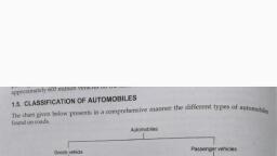
VEHICLE CLASSIFICATIONS (TYPES OF AUTOMOBILE), The automobiles are classified by the following ways,, 1. On the Basis of Load:, • Heavy transport vehicle (HTV) or heavy motor vehicle (HMV),, • Light transport vehicle (LTV), Light motor vehicle (LMV),, 2. On the Basis of Wheels:, • Two wheeler vehicle, for example: Scooter, motorcycle, scooty, etc., • Three wheeler vehicle, for example : Auto rickshaw,, • Three wheeler scooter for handicaps and tempo, etc., • Four wheeler vehicle, for example: Car, jeep, trucks, buses, etc., • Six wheeler vehicle, for example: Big trucks with two gear axles., 3. On the basis of Fuel Used:, • Petrol vehicle, e.g. motorcycle, scooter, cars, etc., • Diesel vehicle, e.g. trucks, buses, etc., • Electric vehicle which use battery to drive., • Steam vehicle, e.g. an engine which uses steam engine., • Gas vehicle, e.g. LPG and CNG vehicles, where LPG is liquefied
Page 6 :
4. On the basis of body style:, • Sedan Hatchback car., • Coupe car Station wagon Convertible., • Van Special purpose vehicle, e.g. ambulance, milk, van, etc., 5. On the basis of Transmission:, • Conventional vehicles with manual transmission,, e.g. car with 5 gears., • Semi-automatic, • Automatic: In automatic transmission, gears are not, required to be changed manually., 6. On the basis of Drive:, • Left hand drive, • Right hand drive
Page 7 :
7. On the basis of Driving Axle, • Front wheel drive, • Rear wheel drive, • All wheel drive, 8. Position of Engine:, • Engine in Front - Most of the vehicles have engine in the front. Example:, most of the cars,, • Engine in the Rear Side Very few vehicles have engine located in the rear., • Example: Nano car., 9. Based on purpose, • 1. Passenger vehicles – car, bus, motorcycle, • 2. Goods vehicles – lorry, truck, pick up, 10. Based on make, • 1. Maruti Suzuki 2. Hindustan motors, • 3. Tata motors 4. Mahindra & Mahindra, • 5. TVs motors 6. Hero motocorp, • 7. Ashok Leyland 8. Eicher motors, • 9. Force motors 10. Bajaj auto ltd, • 11. Royal Enfield, • 12. Volvo, Volkswagen, merc Benz, bmw, caterpillar, Bentley, Audi etc.
Page 8 :
CHASSIS LAYOUT, • The chassis is formed by the frame with the frame side, members and cross members. The frame is usually made of, box, tubular and channel members that are welded or, riveted together. In addition to this, it comprises of the, springs with the axles and wheels, the steering system and, the brakes, the fuel tank, the exhaust system, the radiator,, the battery and other accessories. Along with this the, frame supports the body, • Chassis is a French term and was initially used to denote, the frame parts or Basic Structure of the vehicle. It is the, back bone of the vehicle. A vehicle without body is called, Chassis. The components of the vehicle like Power plant,, Transmission System, Axles, Wheels and Tyres, Suspension,, Controlling Systems like Braking, Steering etc., and also, electrical system parts are mounted on the Chassis frame. It, is the main mounting for all the components including the, body. So it is also called as Carrying Unit.
Page 9 :
An automobile is made up of mainly two units,, these are Chassis and Body., , “Frame” + “Base components” = “Chassis”, “Chassis” + “Body” = “Vehicle”
Page 10 :
Layout of Chassis and its main Components
Page 11 :
The following main components of the Chassis are:, 1. Frame: it is made up of long two members called, side members riveted together with the help of, number of cross members., 2. Engine or Power plant: It provides the source of, power, 3. Clutch: It connects and disconnects the power from, the engine fly wheel to the transmission system., 4. Gear Box, 5. U Joint, 6. Propeller Shaft, 7. Differential
Page 12 :
FRAME, • Functions of the chassis frame:, 1. To carry load of the passengers or goods, carried in the body., 2. To support the load of the body, engine, gear, box etc.,, 3. To withstand the forces caused due to the, sudden braking or acceleration, 4. To withstand the stresses caused due to the, bad road condition., 5. To withstand centrifugal force while cornering
Page 13 :
TYPES OF CHASSIS FRAMES, • There are three types of frames:, 1. Conventional frame, 2. Integral frame, 3. Semi-integral frame, 1. Conventional frame: It has two long side members, and 5 to 6 cross members joined together with the, help of rivets and bolts. The frame sections are, used generally., a. Channel Section - Good resistance to bending, b. Tabular Section - Good resistance to Torsion, c. Box Section - Good resistance to both bending and, Torsion
Page 14 :
2. Integral Frame: This frame is used now a day in most, of the cars. There is no frame and all the assembly, units are attached to the body. All the functions of, the frame carried out by the body itself. Due to, elimination of long frame it is cheaper and due to less, weight most economical also. Only disadvantage is, repairing is difficult., 3. Semi - Integral Frame: In some vehicles half frame is, fixed in the front end on which engine gear box and, front suspension is mounted. It has the advantage, when the vehicle is met with accident the front frame, can be taken easily to replace the damaged chassis, frame. This type of frame is used in FIAT cars and, some of the European and American cars.
Page 15 :
VARIOUS LOADS ACTING ON THE FRAME:, Various loads acting on the frame are:, 1. Short duration Load - While crossing a broken, patch., 2. Momentary duration Load - While taking a curve., 3. Impact Loads - Due to the collision of the vehicle., 4. Inertia Load - While applying brake., 5. Static Loads - Loads due to chassis parts., 6. Over Loads - Beyond Design capacity
Page 16 :
BODY:, • Body is the superstructure of the vehicle and it is, bolted to the chassis., Types;, • Car,, • Truck,, • Tractor,, • Delivery van,, • Jeep,, • Bus, etc..,
Page 18 :
MAIN COMPONENTS OF AUTOMOBILE AND, RTICULATED VEHICLES:, • The automobile can be considered to consist of five, basic components:, (a) The Engine or Power Plant: It is source of power., (b) The Frame and Chassis: It supports the engine,, wheels, body, braking system, steering, etc., (c) The transmission which transmits power from the, engine to the car wheels. It consists of clutch,, transmission, shaft, axles and differential., (d) The body., (e) Accessories including light, air conditioner/hearer,, stereo, wiper, etc
Page 19 :
ENGINE-CYLINDER ARRANGEMENTS, ARRANGEMENT OF CYLINDERS:, • Engines are also classified according to the arrangement of, the cylinders: IN-LINE with all cylinders cast in a straight, line above the crankshaft; V-TYPE with two banks of, cylinders mounted in a V- shape above the crankshaft;, HORIZONTAL OPPOSED with cylinders arranged 180, degrees from other with opposing cylinders sharing a, common crankshaft journal; and RADIAL with the cylinders, placed in a circle around the crankshaft, • IN-LINE - In-line is a common arrangement for both, automotive and truck applications. It is commonly built in, four- and six-cylinder configurations., • V-TYPE - V-type is also a common arrangement for both, automotive and truck applications. The V-type engine in a, six-cylinder configuration is suitable for front-wheel drive, cars where the engine is mounted transversely.
Page 20 :
Reciprocal engine can be classified on the basis of the arrangement of, cylinder (Only applicable for multi-cylinder engine). Popular cylinder, arrangements are described below, , In-line engine:, This is the most common in an automobile engine. This type, of engine arrangement has only one cylinder bank. i.e. all, cylinders of engine arranged in linearly, and all of them, transmit power to a single crankshaft. Inline engine with four, and six cylinders is popular in automotive industries.
Page 21 :
Advantages inline engine, • Design of engine block simple, cheaper., • Running of four-cylinder inline engine is smoother, than the one or two cylinder engines., • Inline engine design does not need heavy, counterweights., Why inline engine arrangement not popular for high, power cars?, • Because of simplicity, inline engine is popular in, economy cars. However, it suffers secondary, • imbalance and causes minor vibration in the smaller, engine. This vibration also increases as, • the size and power of increases. For this reason, the, powerful engine does not adopt inline arrangement.
Page 22 :
V engine: V engines have two cylinder banks and one crankshaft., It is literally the assembly of two inline engine arrangement (appear, to be in "V" shape). This arrangement reduces the overall engine, length, height and weight compared to the equivalent inline, arrangement. Two cylinder banks inclined at an angle to each other, and also each of them inclined to crankshaft. The angle between two, cylinder banks is known as bank angle. In narrow bank angle V, engines, cylinders are combined into a single cylinder block. Engine, with more than six cylinder usually adopts this cylinder arrangement., Most high powered automobile use eight cylinder v engine (four, engine is in inline on each side of V).
Page 23 :
Radial Engine, , • In a radial engine, the cylinders, arranged in equally spaced, around the one crankshaft. i.e., the cylinders are arranged, radially in a circle. Pistons of, these cylinders are coupled to, the same crankshaft. The radial, arrangement is widely used in, large air crafts until gas turbine, engines became predominant. In, air cooled aircraft engine with 3,, 5, 7 or 9 cylinders are used radial, arrangement. For the higher, capacity of engine multi-row, radial engine is used.
Page 24 :
Opposed cylinder engine/ Flat engine/ Boxer engine, • In this type of arrangement two cylinder banks (or, two inline-engines) in the same plane but opposite, side of the crankshaft. One of the advantages of an, opposed cylinder engine is that it inherently well, balanced. The type of engine arrangement found, application in small aircraft.
Page 25 :
Opposed piston engine, • In this type of arrangement, single engine cylinder houses, two piston and has no cylinder head. Each piston drives two, separate crankshafts. The movement of piston made, synchronized by coupling this two crankshaft. The type engine, usually working on the principle of two-stroke engine. The, advantages opposed piston includes, it get rid heavy cylinder, head, and it is a well balanced arrangement. The opposed, piston engine is used in large diesel plants.
Page 26 :
Delta type engine/ Napier Deltic engine, • It is a combination, of three opposed, piston engine., The piston of this, engine is coupled, to three, interlinked, crankshafts.
Page 27 :
X engine, • This is a variation of V, type with four banks, of cylinder attached to, the single crankshaft., This twinned V block, engine has four banks, and appeared as X, shape. X type, arrangement is, extremely uncommon, because of its, complexity and, weight.
Page 28 :
H engine, , • In this type two, opposed cylinder, type is, connected to two, separate but, interconnected, crankshaft. It, shows excellent, mechanical, balance.
Page 29 :
U type engine, • In u type engine, two, separate straight, engine joined by, using gears or chains., It appears in the, shape of U. This, cylinder arrangement, is uncommon as it is, heavier than the, similar V engine.
Page 30 :
W engine, • It is similar to V engine but it has three or four, cylinder bank engine banks.
Page 31 :
POWER REQUIREMENTS, • The motion of a vehicle moving on a road is, resisted by aerodynamic forces, known as wind, or air resistance, and road resistance which is, generally termed as rolling resistance. In, addition to these two types of resistances, the, vehicle has to overcome grade resistance when, it moves up on a gradient, because the weight, of the vehicle is to be lifted through a vertical, distance. Hence, the power required to propel a, vehicle is proportional to the total resistance to, its motion and the speed.
Page 33 :
TRACTIVE EFFORT (TE), • If the rear wheels of the vehicle in the figure are driven, with no slip taking place between the tires and the level, road surface, the wheel force or the tractive effort (TE) is, equal to the torque at the driven wheels (Tw) divided by, the rolling radius or effective radius (Rw)
Page 35 :
Maximum value of TE, • If the rear wheels have such a torque applied to, them that they are on the point of slipping in the, plane of the wheel, then the value of adhesive force, between tire and road surface has been reached (φ, WR), where φ is the coefficient of adhesion, between tire and road surface, and WR is the, weight on the rear wheels. Under these conditions, the engine torque has reached the maximum useful, value for the present set of conditions, as any, increase would only result in slip and lower, acceleration. Static friction is higher than kinetic, friction.
Page 36 :
Traction and Tractive Effort, • The force available at the contact between the drive, wheel tyres and road is known as ‘tractive effort’., The ability of the drive wheels to transmit this effort, without slipping is known as ‘traction’. Hence, usable tractive effort never exceeds traction. The, tractive effort relate to engine power as follows.
Page 37 :
When the tractive effort F>R, the total resistance on level, road, the surplus tractive effort is utilized for acceleration, hill, climbing and draw-bar pull.
Page 38 :
VEHICLE PERFORMANCE CURVES, , • Road Performance Curves: Acceleration, Gradability and Drawbar Pull, • Passenger car performance is based on acceleration, ability to go up a, slope, top speed, fuel economy, noise level, and durability. Transmission, gearing is designed to provide maximum acceleration at low speed by, holding the driving wheel torque output at the point of impending wheel, spin. As wheel spin occurs, the acceleration decreases from the maximum., Also the gear is designed for maximum fuel economy when the engine is, developing 80% of its maximum torque as the automobile is moving at a, constant speed. This gives 20% additional torque for acceleration. The, power required to drive an automobile increases as the cube of the speed, i.e. it takes eight times the power to double the speed. When the power, available matches the power required to push the vehicle, the speed, becomes constant. Excess power is required for acceleration and hill, climbing. Maximum speed is reached when there is no excess power, remaining. Figure 31.3 illustrates the variation of full-throttle power, available at the wheels for four gear ratios with road speed. A curve,, showing the power required by vehicle at various road speeds is also, presented. At any speed, the difference of ordinates of power available and, power may be shared by all the three items as and when required. Power, required by vehicle gives the surplus power, which can be utilized either for, acceleration or for drawbar pull or for hill climbing. Or else the surplus
Page 39 :
Fig. 1 Road speed vs., power available at, wheels., , By using the formula given in section 1, the power available as indicated in Fig. 1 can, be converted into tractive effort. Hence tractive effort performance curves for four gear, ratios can be plotted against road speed as in Fig. 2. In this figure a road resistance, curve is also presented. The difference between the ordinates of tractive effort and road, resistance at any road speed gives the surplus tractive effort, which is utilized for, acceleration, drawbar pull and hill climbing.
Page 40 :
Fig. 2 Road speed vs. tractive effort.
Page 41 :
• Acceleration, • When the vehicle is accelerated, its rotating parts are also, accelerated depending upon their moments of inertia and the gear, ratio in the drive line. Due to this, weight of vehicle is increased from, W to We. This increased weight, We, is called the ‘effective weight’ of, the vehicle. When surplus power, i.e. surplus tractive effort is fully, utilized to acceleration, then
Page 42 :
• Gradability, • The maximum percentage grade, which a vehicle, can negotiate with full rated condition, is known as, ‘gradability’. Hence,
Page 43 :
• Drawbar Pull, • When the excess power is fully utilized for pulling extra load, attached to vehicle then,, • Maximum drawbar pull = Tractive effort—Road resistance =, (F— R)., • Road resistance in this section is made up of rolling resistance, and air resistance. Figures 1 and 2 show that maximum, surplus power and hence maximum surplus tractive effort are, provided at very low speeds of the vehicle. Therefore, for, acceleration from start, for climbing steeper gradient and for, large drawbar pull, first gear is best suited. Maximum road, speed is achieved in the gear when power available equals to, power required (Fig. 1) and tractive effort becomes equal to, level road resistance (Fig. 2). If the vehicle is desired to run at, a lower speed, the throttle is adjusted accordingly so that the, part throttle power available curve intersects the power, required curve at the desired road speed. This is shown in Fig., 1.
Page 44 :
• Example: The coefficient of rolling resistance for a truck, weighing 62293.5 N is 0.0182 2 and the coefficient of air, resistance is 0.0276 in the formula R = KW + KqAV, N, where, A is m of frontal area and V the speed in km i hr. The, transmission efficiency in top gear of6.2:1 is 90% and that, in the second gear of 15:1 is 80%. The frontal area is 5.574, m. If the truck has to have a maximum speed of 88 km i hr, in top gear calculate: (i) the engine B.P. required;, (ii) The engine speed if the driving wheels have an effective, diameter of 0.8125 ni; (Hi) the maximum grade the truck, can negotiate at the above engine speed in second gear;, and (iv) The maximum drawbar pull available on level at, the above engine speed in second gear.
Page 47 :
Thank You…., ?
 Learn better on this topic