Notes of SY EJ, Principles Of Elect. Comm & CEL Ch. 4 Wave Propagation Complete chapter notes.pdf - Study Material
Page 1 :
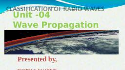
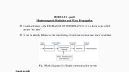
CHA, , 4, , Wave Propagation, , Unit V, Syllabus, Concept of propaga, gation of, , height and virtu, rtual, , height,, , radio waves; Ground, Wave, Critical frequency,, , propagatio, , Sky wave: lonospheric layers, Concept of actual, , skip distance, skip zone, concept of fading, maximum usable, multiple hop sky wave propagation; Space wave propagation: line of sight, multipath space wave propagation, opica, , frequency, , and radio honzon, shadow zones; Duct propagation (microwave space-wave propogation); Troposphere scatter, propagation., , 41, , Introduction, , C, , Blectromagnetic spectrum shows various forms of, , e,, , speed of light in free space, , permittivity of the medium, , =, , electromagnetic radiations like radio waves, infrared,, , visible light, ultraviolet, X-rays, and gamma rays etc., , 4.2, , Concept of Radio Wave Propagation, (MSBTE-s-15), , Electromagnetic radiation comprises of electric field as, well as magnetic field properties in free space or in, some physical medium. The waves are known as TEM, , (transverse electromagnetic) waveforms. TEM, , waves, , MSBTE Question, 0.1, , What are the differenttypes of wave propagation ?, , (-15, 2 Mark, , (Ref. Sec. 4.2), , have mutually perpendicular electric field, magnetic, , ficld and direction of propagation., Radio, , waves are, , Antenna acts, , as a, , generated, , with the, , conductor, , or set, , help, , of, , antenna., , of conductors in the, , waves, , travel, , through, , free space, through, , some, , thoroughly, material conductors, but it cannot pass, radio, like seawater. Rather, , through lossy, , waves reflect, , conductors, from good, , etc. and, , aluminum,, , conductors ike copper,, , they get, , refracted when, , they, , he, , speed of, , 3pace, , is, , same as, , velocity of radio, , that of, waves, , needs to, , change the straight, , line, , path, , as, , there is, , of the radio, , light, i.e., 3, , x, , travelling other, , waves, , in free, , 10 m/s. The, , than free space, , is given by,, , Definition of radio wave propagation i is, term used to explain the behaviour of radio waves when, they are transmitted, or are propagated from ane point, on theEarth to another, , pass, , medium., from one medium to another, transmission, , wave, , change in the medium., , formation of the radio waves., , Radio, , Generally radio waves travel in a straight line path; but, where the earth and atmosphere alter their paths, the, , There, , are, , many factors which affect, , waves, , like, , frequency, , travelled, waves, , by, , propagation, , of the radio waves, distance to be, , the wave, medium, , through, , which radio, , travel, the objects in the path of propagation, etc., , The radio, , waves are, , almost similar to light waves and, There, , e, , where,, , V, , velocity of radio, , waves, , in the medium, , of, , are, , they are expected to behave like light waves., the, three major propagation mechanisms followed by, waves namely: Reflection, Refraction and Diffraction.
Page 2 :
Wave Propagation, , Principles of Electronics Communication (MSBTE), , 4-2, , Depending on the frequency of the radio waves, there, are four types of the propagation methods:, , 1., , 1., , Froe space, , 2., , Ground, , (Direct wave), space waves, , GrounaWOves((slong the, , propegation, , wave, , propagation, , 3., , Sky wave propagation, , 4, , Space wave propagation, , Free spece, , shpere, , (Refnected from, lonosphere), , 8urfece), , sky waves, , Receiver, , Surtice of the a t, , antenna, , Transmitter, , antenna, , propagation, , In this, radio waves travel in free space away from the, , obstructions which will affect the, , propagation path., , The only factor that affects free space propagation is, the distance between the transmitting antenna and the, , destination., (101)Fig. 4.2.1, , Along with the distance, the strength of the signal, , (MSBTE, , Ground wave propagation, The radio, , wave, , propagation, , in which, , waves, , along, , the surface of the earth is known, wave propagation'., , All the radio, , signals transmitted, , as, , in the, , travel, , (S-13,4Marke), daytime Q.2 Explain propagation of ground waves., , (RefSec. 4.3), , along the curvature of the earth by means of diffraction., , (W-13,4Marks, , O. 3 Desoribe any three features of ground wave, , propagationalong with neat sketch., , (Ref. Sec. 4.3), , Sky wave propagation, Waves in HF range and, frequencies just above and, below HF get reflected back from the ionized, layers of, the atmosphere are known as, sky wavesS., , (S-14,4Marks), , 4Explain ground, wave propagation alorng with sketch, Ref. Sec. 4.3), (S-17, W-17, 4 Marks), Ground wave progress, It is, , along the curvature of the earth., particularly important in LF and MF waves. At, , launched into the sky and get reflected, back from ionized layer., , frequencies, , To cover maximum distance between, transmitter and, , propagation is carried out., , waves are, , receiver, multiple reflections must take place., , 4, , ground wave propagation, , (Ref.Sec 43), , Frequencies below HF (High Frequency) range travel, , These, , -S-13, W-13, S-14, S-17, W-17), , MSBTE Questions, , 'ground 1Describe, , propagate by ground wave method., , 3., , of the earth, , Space wave propagation, Waves above HF range, known as space waves, , There, , travelling, , in, , straight, , line, , are, , are, , various, , Many, , up to 2 MHz, , so, , many factors like, , wave, , properties, , of earth and, , atmospheric layers affect on the ground waves., waves are, , frequency dependent and, generally vertically polarised to, are, , prevent current induced by, Where Authors, , generally ground, , The waves follow, curvature, it can go far, beyond the horizon., , of these factors, , hence these, , lech-Neo Publications ., , propagation methods, , 4.3 Ground Wave Propagation, , reduces and signal tends to travel lesser distance., 2, , Different, , ground itself., , inspire innovation, , SACHIN SHAH Venture
Page 3 :
|, , Prindiples ot EleCtronics, , There are, , Communication, on (MSBTE), , two, , major problems, wave propagation. They are associated with ground, , Absorption, , 1., , by, , the, , ground:, , current in the ground over, , loses some energy, , which, , 4-3, , by absorption by the, ground., , result of, , As, , a, , the, , horizontal surface as, , undergoes 180 phase shift., , Therefore, wave gets partial cancellation., , A wave induces, it passes and thus, , Attenuation by diffraction: Whenever, abeam of, light or any other wavefronts, passes through, narrow gap or from the, edge, it gets spread out, creating interference., , 2, , Wave Propagation, , Direct wave, , Reftected wave, , Transmitter, , Receiver, , .Eart, , diffraction,, , the wavefront tilts towards, shown in the Fig. 4.3.1., , * * *, , *******, , Direction of propagation, , Successive, wavefronts, , Increasing, , angle of tilt, , (10Fig. 4.3.2: Cancellation due to ground reflection, , Advantages, Surface of the Earth, , 1., , Reliable means of communication almost independent, of weather and solar activities., , ****************, , 2., , With proper amount of transmission power at LF, range, , *, , of the communication can be increased., , Disadvantages, 1., , Ground, , waves are, , quickly above about, , attenuated very, , 2 MHz, hence it has lack of spectrum space., , (1023Fig. 4.3.1: Ground wave propagation, As the, , wave, , progresses, the, , resulting in, , and, , more, , will, , even w o r s e n s as, , If the, , the distance between, , Cancellation, , due to, , distance between, , as, , also, strength of the signal, , beyond, , certain limit, the, , ground, , transmitter, , reflections :, , When the, , a, well. But there is, to, cancel led out due, , the, reflected from, , ground, , surface. Refer, , are, , used in LF propagation, wavelengths, , frequencies,, because at low, are, , almost, , equal, , are, , physical height of an antenna required, is also greater for obtaining good eficiency., , more, , and hence,, , Applicatlons, , 1., ., , Local Standard Broadcast (AM), , 2., , Loran, , (long, , range, , C, navigation developed in USA), , navigation at relatively, short ranges., , VLF propagatlon, in, VLF propagation is used, water where, , absorption and, , Fig. 4.3.2., , frequencies, , good conductors, , are, , attenuation are, , like, , sea, , and, below 100 kHz, , less., , the direct, and, , reflected path, path and the, innoration, Authors inspie, here, , Tech-Neo Publications., , they, , as, , take, , This happens, , wave, , and receiver is smaller,, , straight line path, may get, possibility that this signal, signal, , As, , transmitter, , "lies down and dies"., , the, , 3., , distance increment., , distance increases, , wave can, , It requires high power., , increased losses. The situation, , and receiver increases, reduces with, , angle of tilt increases more, , 2., , wave, , SACRIN, , SHAH Vemture
Page 4 :
Principles, n, , of Electronics Communication (MSBT3, , of tilt, this type of propagation, the angle, , c o m m u n i c a t i o n, , determines, , Long, , distance, , because, , the longer distance communication., Some, , As the frequencies, , and hence,, , are too, , waves, , vanishing. Thus, it, , travel, , less, wavelengths, , distances, , longer, , reliable, , becomes, , are more, , before, , means, , of, , and, , mobile, , communications, , (like, , radio, , are, , communications), , molecules are, , of, so degree, , ionization, , The level of, , region in, ionized, , is greater, , ionization, , ionospheric, , solar, due to, , layers., , radiation,, , in daytime., with distance above, , increases, , differ in, , navigation, , using, , LF, , ionospheric layers, There are four, above earth surface, 400 Km, to, 60, from, , heights, , namely, , For VLF communication,, , required, , a, , is possible, , which can, , propagation., , are, , air, , in, , range, , earth surface., , communication over long distances., , Generally ship, , of, , refraction, , in HF, , and also this, , really tall masts for antennas, for, type requires high power, , transmission., , 1., , DLayer, , 3. F layer, , 2., , E layer, , 4., , F, layer, , Broadly lonosphere is, , divided into three, , into, and Fand Fis divided, , 4.4 Sky Wave Propagation, , F,, , regions : D, EB, , F2, , and, , every 11 year, , cycle, , as, , it, , lonization in the upper part of the atmosphere plays an, , Ionization levels, , important role in propagation of HF radio waves., , depends, , Because of solar energy, ionization takes place in, , known, , various layers of different heights and different, , is concerned., cycle are important as high end HF, , thickness., , Signal returns back from ionospheric layer by, , These layers are responsible for reflection of the waves, , refraction., , coming from earth. Some of these frequencies are, , Reason of bending down of the wave, , passed and some are reflected back towards earth., , EM waves appear to be reflected from the ionospheric, , on, , as, , change, , 11 year, the solar activities. This, , sunspot, , cycle is, , in this, cycle. Specifically the peaks, , means, , of, , Though the, , layers, they are actually refracted., , 4.4.1, , lonosphere, The ionized air contains free electrons which moves in, , (MSBTE S-13, W-13, S-14, S-18), , the presence of radio waves which are actually EM, , MSBTE Questions, , waves, , 0.1 Describe varnous layers of ionosphere, , They both interact with each other causing reduction in, , a.2, , the refractive index of the, , (Ref. Sec. 44.1), (S-13,4 Marks), Draw labelledsketch ofionoephere. What, changes, , down towards the earth., , takes place inionosphere atnight ?, , If the rate of the, , Ref. Sec. 44.1), (W-13, 4 Marke), Q.3 Explainionospheriopropagation withpropersketch., (Ref. Sec, 4,4.1), , (514,4Marke, , layer, , and, , Ret, , becomes necessary for the, refraction, , Ionosphere is defined as the layer of the atmosphere, , that is ionized due to solar and cosmic radiations. It is, , bend, , change of the refractive index per, height is sufficient, then wave will, gradually, become parallel and will, get absorbed by the layer, instead of bending down., As the, , (S-18,4 Marks, , wave, , unit, , Q.4 Describe ionosphere with neat sketch, , Sec.44.1), , hence,, , frequency increases, more, , all the waves, , by the layers., , are, , refracted, some, , amount of, , ionization, take place. Not, of them are absorbed, to, , very important in Sky wave propagation mechanism., Tech-Neo Publications., , here Authorsinspire innovation, , .d SACHIN SHAH, , Venture
Page 5 :
Principles of Electronics Communication, Refer Fig. 4.4.1., , (MSBTE), , 4-5, , Wave Propagation, , Outer atmosphere, , reglon, Above, , 400 km, , F2-Layer, , 250-400 km, , F1-Layer, , 140-250 km, , lonosphere, , E- Layer, , 90-140 km, , D-Layer, Tropopause, , 20-90 km, , Stratosphere, , Troposphere, , 10-20 km, **, , Earth, , (1D5Fig. 4.4.1: Ionosphericlayers, Refer Table 44.1. It shows the details of ionospheric layers., Table 4.4.1: Details of ionospheric layers, , Sr., No., , 1, , 2, , important Features, Height abovethe Thickness Frequencies thatFrequenclesthat Existence at, (inkm) are refracted from are absorbedby night time, of the surfaceof the, thelayer, thelayar, earih(in km, ayer, Does not, Lowest layer, 10, Some VLF and LF MF and HF, About 70, D, exist, Name, ame, , E, , 3, , 25, , About 100, , Daytime: 20 Some HF waves, , Daytime: 250 to, , 200, , MF to HF, , 400 km, Night: 300 km, , eo Publieations, , ., , Above 10 MHz, , Does not, , exist, , FAbout180, , F2, , Below 10 MHz, , Where Authors inspire, , Some HF waves .Exists at, , night, , range Exists at, night, frequencies, , Few, , GHz, , Sometimes, sporadic E (E), layer exist with E layer. This, E, layer persists at night also., , At night, F and Fa combine to, form Flayer., so it, lt is the topmost layer is, highly, ionized. So ionization, remains present at nightalso., , So t, , innovation, , exists at night, , A SACHINSHAH, , Venture
Page 6 :
Principles of Electronics Communication (MSBTE), , Wave Propagation, , 4-6, , To reach the receiver, the wave can take multiple hops, , 1., , The virtual helght and the actual helght, , by reflection from the ground and refraction from the, , (MSBTE S-13, W-15, W-17), , ionospheric layers. But this may reduce the signal, , Refer Fig. 4.4.2., , strength to a great extent., , Projected path, , lonosphere is actually changing from hour to hour, year, to year. Hence, all the predictions regarding this are, , actually approximate., Hence, the users of ionospheric communication like, Actual, path, , shortwave broadcasters or military transmit on the wide, number of frequencies in HF spectrum so that, , frequency diversity'., , height, , Ground surface, , (106Fig. 4.4.2: Actual and virtual heights of an ionized layers, , Terminologies Associated with Sky, , There is gradual bending in the wave rather than the, , Wave Propagation, , sharp bending, when the wave is refracted., , (MSBTE s-13, W-13, s-15, W-15,s-17, W-17, s-18,), , However, below the ionized layer, the refracted ray and, the incident ray follow the same path as it would have, , MSBTE Questions, a. 1 Bxplain the term Maximum usabie frequency, , been followed if the reflection would have taken place, , vith, , from a surface located at greater height is called as, , respect to sky wave propagation?, , (Ref. Sec.4.4.2(2)and 44.2(3) (S13,4 Marka), a.2 State the effect of Actual Height insy wav, , virtual height'., If the virtual height is known, angle of incidence can be, , propagation? Explain VerticalHeight with respect, to, , sky wave propagation., , (Ref. Sec. 44.2(1)), , (6-13,4 Marke, , determined., , 2., , Critical frequencyy, , a. 3 Explain skip zone and skip distance with neat, , (MSBTE s-13, W-13, s-15, S-17), , diagram, , It is the highest frequency that will be returned down, , (Ref. Sec. 4.4.24) &(5)), , (-13,18,2 Marks, , the earth, , a. 4 What do you mean by critical frequency and, maximum usable freguency with reference to sky, , wave propagation ? (Ref.Sec.4.4.2(2) and ()), (W-13, 4 Marks), (S-15,4 Marke), a.5 Explain, (1) Critical Frequency (Ref. Sec, 4.4.2(2)), (2), , Virtual, , height, , least, , one of them should reach the receiver. This is known as, , 4.4.2, , Actual, , Skip distance, , (Ref., , Sec. 4.4.2(4)), , a. 6 Describe tha term virtual height with the help of, diagram showing ionized layor and the path of, wave. (Ref. Sec 4.4.2(1), , (W-15,4 Marke), , propagation, Define oritical frequency W . to wave, , (Ref.Sec. 4.4.2(2)), Explain virtual heightwith, gaton ith neatsketch., (Ref. Sec 44.2(1)), , incident at normal., It is denoted, , Its value ranges from 5 to 12 MHz, , by Fe, , for F2 Layer., 3., , MUF (Maximum Usable Frequency), , (MSBTE, , points, , when the, , angle, , of incidence is other than, , normal., MUF, , =, , to wave, where,, , f, , =, , Critical frequency f . sec 66, cos 6, Critical, , frequency, A, , Tech-Neo, , Publications .., , Hbere Authors, , inspire innovatio, , S-13, W-13), , used, It is defined as the highest frequency that can be, for sky wave comnmunication between any two given, , S-17,2 Marke), , W17,4 Marks), , when the beam is, , by ionospheric layer, , SACHIN SHAH Venture
Page 7 :
Principles of Electronics, Communication (MSBTE), Angle, , This is called, to, , flat, , as, , the secant law, and it is, , are, , Wave Propagation, , of incidence, , reflecting surfaces., , Normal values, , 4-7, , between, , applicable only, , MUF, , are, , working frequency, , is, , rays, , s, , always, , en, MUF, , f Xsec, , Lower rays, , sec, , Upper, , 1, , rays, , Cos, , -, , Skip distance, , Rx, , Earth, , (107Fig. 44.3 : Maximum usable frequency, 4., , used for, , Escaped, , 8 to 35, , MHz, but they may, increase up to 50 MHz after, unusual solar activities., Naturally, the practical, lesser than that of MUF., , Hence, frequencies just below, transmission., , (1D8)Fig. 4.44: Skip distance, , 5., , Skip zone, , (MSBTE-S-18), , Skip distance, , (MSBTE -S-13, S-15), , Refer Fig. 4.4.5., , lonosph, www*, , It is defined as the shortest distance on earth m sured, from the transmitter at which the sky wave of, , Sky wave, , Sky wave, , not effective, , Ground, , frequency more than critical frequency will be returned, , wave, , Skip, , back to earth., , zone, , Skip distance, , When the angle of incidence is made quite large the, , (1D9Fig. 4.4.5 : Skip zone, , wave returns at a longer distance from the transmitter, , ray 1). And when the angle is gradually reduced,, , It is the region close to the transmitter where radio, , obviously the distance becomes lesser (ray 2 and 3)., , frequencies cannot be received., , And when the angle of incidence is made lesser than, , It is also known as silent zone or dead zone. It is, , ray 3, then the rays won't come back towards the earth,, , generally the region between the point where ground, , as shown in the Fig. 4.4.4., , waves are no longer heard to the point where the sky, , Hence, ray 3 returns at the closest distance amongst all, the transmitted rays and hence, that minimum distance, is 'skip distance'., The frequency which makes the ray come back with, this minimum distance is nothing but MUF for that pair, , wave first returns on the earth., The skip zone, , depend upon, , Ground wave coverage, , (i) Skip distance, , of points., At skip distance, only normal or lower rays can reach, the receiver. However at the larger distances, the rays, , can be received but with interference., , Tech-Neo Publications., , here Authors inspire innovation, , A SACHIN SHAH Venture
Page 8 :
activities. If it is not done, the sky wave may not reach, , 4.4.3 Concept of Multiple Hop Sky Wave, , correctly to the destination receiver as shown in the, , Propagation, The transmission, , Fig. 4.4.6b), , path for, , the, , sky, , wave, , is limited, , by, , two major factors:, 1., , 2, , Concept of Fading, , 4.44, , (MSBTE S-13, w-13, W-14, W-15, S-17, S-18), , Skip distance, , Curvature of the earth, , MSBTE Questions, , Single or double hop means the way the wave can, travel, , by, , one or, , two, , reflections from the, , refractions from the ionosphere., , ground, , and, , When the range of, , sky wave propagation needs to be, increased, the wave has to travel multiple hops to reach, , to, , Wave Propagation, , 4-8, , Principles ofElectronics Communication (MSBTE, , the destination as shown in the, Fig., , 4.4.6(a)., , Q. 1 With the help of figure, explain fading9, , (Ref. Sec. 4.44), , (S-13,2 Marks, , a. 2 What is fading? How its effect can be minimised ?, (Ref.Sec. 444), (W-13, 4 Marke, a. 3 What is Fading ? Write two reasons of Fading,, (Ref.Sec. 444), (W-14,2 Marks), Q. 4 List the major causes of fading., , Ret. Sec. 444), Single-HOFP, , .Double-HOP, , transmission, , transmission, , Transmitter, , Receiver, , (1010Fig 44.6{a) : Multiple hop sky wave, , strength at a receiver., , layer is not taken into, account, , Receiver, , coverage, , means,, , this distance is, , single hop, , can, , be, , the, , path for east west, , wave, , between long, , east, , equal, , to, , 4000 km; that, maximum of 4000 km. But, of the earth is, just over, , communication needs to be set up, west paths, crossing the terminator,, , day-night time difference must be taken into account as, ionospheric layers are strongly affected by solar, Tech-Neo Publications., , be defined, , Where, , Authors inspire innovatio, , as, , interference between the, , paths, , differently., Ultimately the, , whole, , of all the waves, , (S-18, 2 Marks), , the fluctuation in the, , which are transmitted the, by, the different, and, , signal, , signal, , two waves, , same source, , but travels by, the destination, , reaches, is, , actually, , received. Hence, there, , cancellation or reinforcements, , the vector, are, , sum, , chances of, , of the, , signals that may, lengths between the two paths., Fading is more severe for higher, frequencies., Fading may occur because of, interference, , occur, , semi-circumference, 20000 km and hence, multiple hops are necessary., , When the sky, , can, , It occurs due to, , (1011)Fig. 4A.6b): Long distance sky wave, , (S-17,2 Marke, , O.6 Define fading? List the causes., Ref. Sec. 4.4.4), , lonosphere, , different height of, , F layer,, , (Ref.Sec. 444), , It, , Ray misses receiverit, , For, , a.5 Define fading w... to wave propagation, , communication, , F2 layer, , Transmitter, , W-15, 2 Marks, , due to variable, , between the, propagation, between, number of hops to reach the, , lower and upper, rays in sky, the waves, , wave, , taking different, destination, or even in between the, sky waves., , The variations in the, , height, , ground waves, , and, , and densities in the, , ionosphere may cause the fading of the, , signal., , SACHIN SHAH Venture
Page 9 :
Principles of Electronics Communlcation (MSBTE), , Wave Propagation, , 4-9, , To reduce the effect of fading, frequency diversity or, , different amplitudes. Hence, the name selective, , space wave communication can be used., , fading., , AM signals suffers a lot due to fading as compared to, , channel bandwidth., , SSB signal., , signal, , In this,, , bandwidth is greater than, , () Doppler spread : It has two types:, , (a) Fast fading: They occur due to rapid fluctuations, , There are many types of fading. They are divided into, , signal over small, , bandwidths. Distortions in, , large scale fading and small scale fading as shown in, , in the, , Fig. 4.4.7., , the shape of the signal occurs due to fast fading., the, (b) Slow fading: It results from the shadowing by, obstacles like building, mountains, hills, etc., , Fading types, , Large scale fading, , Small scale fading, , Advantages and Disadvantages of Sky, , 4.4.5, , Wave Communication, , Multipath, , Shedowin, , Path loss, , Doppler, , delay spread, , Spreaad, , Advantage, The, , Fast fadingSlow fading, , (1D123Fig. 4.4.7: Types of fading, scale, , It, , fading, , occurs, , to, , obstructions in, , Path loss: This is the attenuation, , is, (ii) Shadowing : This, due to large objects, , of the signals, , the, , or, , obstructions, , fluctuate, , in, , also known, , same, , as, , spectral, Teeh-Neo Publications, , bandwidth, , it, , occurs, , of the, , proportions, , non-selective, , (b) Frequency selective, components, , 2., , and, , If the range between the, more,, , signal, , the, , is less than, , when all the, , received, , signal, , time thickness needs, , transmitter, , and receiver is, , through multiple hops,, , extent., signal strength to a great, , (MSBTE, , W-13, S-14), , different, It affects, , radio, , here Authors inspire, , princi, Q.1 Write frequency range, propagation, two applications of space Waves., , signal, , innovation, , (W-13,4 Marks), space wave propagation with sketch. List its, , (Ref. Sec. 4.5), , with, , (S-14,4 Marks), , (Ref. S, Space, , waves, , travel in, , receiver. Hence,, , straight, , to, line from transmitter, the curvature of the, , they are limited by, , earth., They, , fading., , a, , ionospheric, , advantage and disadvantage, , simultaneously. It is, , fading:, of, , night, , has to travel, , which in turm reduces, , Q. 2 Exlain, , into 2 types:, , In this, signal, (a) Flat fading:, , frequency components, , daytime, , the, , on, , dependent, , MSBTE Questions, , two types, Multipath delay spread:Ithas, , and, channel bandwidth, , is, , wave, , in the, , It is the result of the rapid, Small scale fading:, distance over, over very small, fluctuations in the signal, , It is divided, short time duration., , ), , sky, , blockage of the signal, , transmission path., , 2., , communication., , 4.5 Space Wave Propagation, , by the, , the, , provides, , to be considered., , signal, , long distances and the, propagation, It has two types:, the path of transmission ofthe signal., due to distance travelled, , As, , variations, its, , due, , over, , support for, , continuous, , 1., , Large, , of communication and, , simple mode, , Disadvantages, , Frequency, Flatefading, eve, Tadin9, , 1., , most, , in between the, face the problem of obstacles, , mountains,, travelling path like tall buildings,, , They behave similar to the, , EM, , waves, , hills,, , etc., , in the free space., , A SACHIN SHAH Venture
Page 10 :
Wave Propagation, , P, , (MSEBTE, Principles of Electronics Communication, , 4-10, , ionosphere, , from the, They cannot get reflected back, short as frequencies, because their wavelengths are too, are too, , high., , And, , because surface, , they, , waves, , cannot, , behave, , die due, , to, , surface, , as, , tilting, , antenna, , where,, , d,, h,, , =, , =, , distance, , nearer to the, , Total distance, , can, , be calculated, , d, , above, , the, , as,, , d,+d,, , =4h+4 h, , (1) t is suitable for high frequencies., travels in, , straight line,, , distance is, , more, , increased, , be, , Distance can, , the, , covered., , mountain or, , by, , antenna on, mounting the, , distance, hills but, , beyond 100 km is, , communications., , Concept of Radlo Horlzon and Optlcal, , 4.5.1, , antenna, , ground inm, , waves, , Advantage, , wave, , in km, , the receiving, , the receiving, height of, , transmitters., , (2) As the, , from, , Horlzon, , Receiving, , hardly used in, , commercial, , Line of Sight Propagation, , 4.5.2, , antenna, , (MSBTE, , Transmitting, , -S-18), , antenna, , MSBTE Question, , Q.1 Describeline of sight propagafion in brief, (S18,4Marke, (Ref.Sec 4.5.2), , d=d+d=W2h+2h, , It uses direct path from transmitter to receiver., , din miles, h and h, in feet, , Very higher frequency signals, generally above, , (1D13Fig, 4.5.1 : Radio horizon for the wave, , 30 MHz, does not return to the earth due to peaks in the, , Optical horizon : Horizon is the imaginary line where, earth appears to be meeting the sky. The horizon which, can, , be, , seen, , by, , open eyes is known, , as, , optical, , horizon'., , solar cycles. Many times, terrestrial communication at, these frequencies is making use of line of sight, communication., , The practical communication distance is limited by the, curvature of the earth for line of sight communication., , Radio horizon: For space waves, it is about 4/3, , of the, , optical horizon. This is increased because of the, variable densities of the atmosphere and the diffraction, around the curvature of the earth. This variation in, , densities bend the radio waves slightly towards earth., Hence the radio horizon is given by the formula, , This, , practical working, , distance is actually radio, horizon which is greater than optical horizon., The refractive index of the air decreases with, increase, in the height above the, ground surface. This condition, varies with the weather conditions., one, , third of the, , always possible, in the weather, , where,, , d, , =, , distance from the, , transmitting antenna in km, , h = height of the transmitting antenna above the, , can, , be determined for, , distance, the radio communication is, in LOS, , propagation though variability, , conditions occur., , propagation, higher the antenna placed above, , ground surface,, , more, , will, , be the distance, , explained in radio horizon concept., , ground in m, , This formula, , For LOS, , Approximately over, , receiving, , as,, , 4, = 4Vh,, , Tech-Neo Publications. ...Where Authors inspire innovation, , antenna, , covered,, , as, , The range of LOS can, be extended, though it reduces the, , Due, , to, , this,, , more, , sensitive antennas are, , by diffraction, signal strength to great extent., powerful transmitters and more, , required., SACHIN, , SHAH Venture
Page 11 :
Principles of Electronics Communication(MSBTE), , Wave Propagation, , 4-11, , LOS receiver may pick up signals which are diffracted, , The channel characteristics are actually the sum of all, , or reflected from some sources., , the individual signal characteristics., Example : Consider a wireless phone operating in an, , 4.5.3 Multlpath Space Wave Propagatlon, , office environment. The office environment has many, , The radio signal takes many paths once it is transmitted, from an antenna. Some portions of the wave will, , undergo many reflections from the obstacles like tall, buildings, mountains, moving trains or airplanes, etc., Multipath occurs when the signal takes two or more, paths from the transmitter to reach the receiver., , Receiver will capture the strongest signal which is, , usually the direct ray, when the ray reflects from, , some, , of the obstacles, its strength also gets reduced. And, these reflected rays always arrive at the receiver after, , the direct rays, as they take longer paths., , Practically, the signal at the radio receiver is the sum or, difference of all the incoming signals depending on, their phases., , effect, , on, , the number of, , paths, , that, , reception have, the signal can, , take., Non-directive antennas will radiate the, , signal, , in all, , directions, whereas directive ones will focus the power, in, , one, , signals, , reaching the receiver like file cabinets, desks, doors,, etc. As the signal encounters each of these objects, a, reflection occurs and the net channel characteristics, arise from the sum of all these individual channels., , Multipath fading, multipath propagation resulting from the variety of, signal paths that may exist between the transmitter and, receiver can give rise to interference in a variety of, of the signal, loss of data and, ways including distortion, multipath fading., , The, , Multipath fading occurs due to variety of time delays, taken by the rays taking different paths to reach the, , receiver, Sometimes, , The antennas used for transmission and, an, , obstacles from which the signal can get reflected before, , direction, reducing the strength of reflected, away from the main beam., , obviously, receiver, , phases, , when, , the, , the, , radio, , path lengths, , receiver, , is, , moving,, , between the transmitter and, , changing. This also results in variable, variable signal strengths of the signal, as it, , are, , and, , in the path. At times,, may reflect from different objects, This, there will be changes in the relative path lengths., causes fading of the signal. This is very well explained, , by example given below., , Refer Fig. 4.5.2., , Example, if you are listening to FM radio, station, then sometimes it may happen that FM signal, , While, , Reflected, , gets, , (Delayed) path, , driving, , a, , car, , distoted or appears, , as, , if it is, , breaking, , down at, , certain points., Differential time delay =t, , The reason behind this is that FM receiver is receiving, the FM, , Direct path, , If, , propagation scenario, (1014)Fig. 4.5.2: Multipath, characteristics, , change, , over, , of multipath, , channels, , with instantaneous, , voltage and, , audio, , output., , *, , The, , signal, , usuallyy, , of the channel, time because the geometry, , multipath propagation, , signals, , occurs,, , then, , two or more, , the direct, will appear at the receiver. One is, and another is a reflected signal., , or, , line of sight signal,, , changes., d, eeh-Neo Publications ., , here Authors inspire, , innovation, , SACHINSHAH Venture
Page 12 :
Principles of Electronice Communication (MSBTE), , As these will arrive at different times, because of the, , different path lengths, they will, , Wave Propagation, , 4-12, , have different, , 4.6, , Mlcrowave Space Wave Propagatlon, , Duct Propagation/ Super Refractlon, , frequencies as these two signals are transmitted at, , (MSEBTE-S-13, W-13, S-15, S-17, , slightly different times by the transmitter., , Accordingly, when the two signals are received, together, distortion can arise if they have similar signal, strength levels., 45.4, , MSBTE Questions, , 1, , EXplain duct propagation with thehelp of diagram, , (Ref. Sec. 4.6), , -13, W-13,s-17, 4 Mark, , Q.2 Explain Duct Propagation., , Shedowing, , (Refec. 4.6), Any, , tall, , wave, , signal. As a result, shadow zones will occur., , massive, , or, , Shadowing, , objects will obstruct, , the space, , This is the result of, , in their, , received, path between, , multipath fading, , of the, , signal., , by equation, , To, , of radio, , horizon. Higher is the antenna, mounted, larger is the, distance covered by the wave., also receive such, signals by, caused by objects and if the, object is good, there are chances of, back reflections, areas, , reflections, , conductor,, , also., , There, , are not, , only, , time, , delays but also the phase, differences between the, signal, paths. Hence, cancellation or travelling by different, addition of these, , the, , receiver may occur., , As, , a, , get, , result of, , distortions, For fixed, , waves at, , shadowing and multipath distortion,, , ghost images, , we, , the television, screens and, in the audio, in, signals FM radio., , receivers, directional antennas can be, used, , reduce this, , to, , problem; but still for moving, receiver, the, of, problem multipath fading, persists., Hence it is, recommended that, there should be, more, than one antennas, mounted on moving, receivers to deal, with the, problem of multipath fading and, but it increases cost, shadowing;, , -Neo Publications .., , ground, the air, and refractive index decreases, along, with the increase in the, height., Under certain conditions, , trapped, , especially, , over, , water,, , into the cooler air. As, , the refractive index decreases, more, with height. This, , rapidly, , a, a, , layer, result,, , than usual, , generally happens about 30 m from, ground surface (generally in, troposphere). This is, known as 'duct' or the, 'super refracting layer., This rapid reduction in, refractive index bend down the, microwaves. Thus, microwaves, gets refracted from the, at, , the, , duct and gets reflected, by the, , ground surface., hopping of the microwaves is obtained as, , And, , shown in the, , Fig. 4.6.1., , similar duct is formed, when a layer of, high refractive, index and low refractive, index settle on each, other and, waves get, , A, , trapped into it., , on, , of the, , go above the surface of the, , of warm air gets, , reduce this, shadowing effect, antennas should be, mounted higher than indicated, , Some, , we, , density decreases, , is the effect due to which the, , signal fluctuates due to obstacles, transmitter and receiver., , As, , (S-15,4Ma, , This will, , sometimes, , propagate, even, , and receiver, , Though, , are, , waves over, , 1000 km,, , longer distances;, provided both transmitter, a, , located in the duct., , it seems, very, still it is not of, , good, , propagation mechanism, commercial, use as the, main, for the, formation of the duct is, requirement, temperature inversion., It has, of fading of, disadvantage, the signal when, for longer, used, distance, , communication., , system., , bere Autbors, , inspire innovation, , SACHIN SHAH Venture
Page 13 :
Principles of Elect nics Communication (MSBTE), 4-13, Duct effect, , Upper atmosphere, , troposcatter communication can be, obtained when antennas, are installed on, height and, directed, , wamed air, , towards the horizon., , col, (1D15Fig. 4.6.1: Duct, , 1., , propagation, , 2., , Tropospherlc Scatter Propagatlon, , troposphere is the lowest layer of the, atmosphere., The irregularities in the, troposphere can scatter, temperature, , irregularities, , variations, the atmosphere., It is used for the, , the, , the water, , on, , path lengths, , And the best frequencies used, , caused by the, , are, , vapour content of, , 3., , of, , operation, communication system., Less number of, It is useful, , is, , repeaters, , greater than the LOS, are, , needed,, , as, , range is, , communications means over the water, over, , difficult terrain like mountains, etc., , Dlsadvantages, Disadvantages, 1., , of about 80 to 800, km., , 3., , 250 MHz to 5GHz., , 4., , are, , Range, , higher., , The, , radio waves. These, , Advantage, , Trapped waves, , Earth surface, , A7, , Wave Propagation, , Best results of, , It, , requires large transmitting power., It requires antennas with, higher gain., It requires more sensitive, receiving antennas., It faces the issue of, , Refer Fig. 4.7.1., , fading, , at, , fading., , To reduce the effect of, , least two antennas,, , separated by 100, wavelengths, are needed to be installed on each side of, , Stratosphere, , radio stations. This means,, space diversity systems, to, employed tackle the problem of fading., , Scatter, , volume, , 4.8, , Scatter, angle, , Troposphere, Transmitting, , Comparison, (MSBTE -S-15, W-15, S-17, W-17, , Receivin9, , site, , site, , MSBTE Questions, C. 1Compare ground wave and sky wave propagation, or four points. (Ref. Sec. 4.8), 15, Marks, Compare ground Wave and, , (101)Fig. 4.7.1 Tropospheric scatter propagation, The transmitting antenna is placed in the direction of, the receiving antenna but the receiving antenna is, , located above the horizon., unat their beams intersect each other midway between, , them., of the transmitted energy continues in the space, Most, L n e small portion of the energy is scattered. The, 0al scattered energy reaches the receiver., not a, scatter volume, and, Point; so the waves may take multiple paths ana Dence, , is via, , a, , wave, , propagation on the basis of frequency range and, method, , of wave propagation, , (Ref. Sec. 48), Compare, , bese two are directional antennas. They are so placed, , propagation, , are, , (W-15,4Marks), , sky wave propagation and space wave, , propagation w.r. to following ponts, Applications, , Frequency range, , Polarization, 4 Efect of fading, , (Ret. Sec. 4.8), (S-174Marks), a.4 Compare ground wave propagation,s wave, propagation and space wave propagaton, 17,4Marks, (Ref. Sec 4.8), , Problem of fading occurs in this., , cca-Neo Publications, , h e r e Authors inspire, , innovation, , A SACHIN SHAH Venture
Page 14 :
Principles of Electronics Communication (MSBTE, able, , 481:Comparlson of ground, , propagation, sky, , of, , wave, , propagation and space, , wave, , Above 30 MHz, , 2 to 30 MHz, , Up to 2 MHz, , operation, 2, , Path followed, , Along the, , curvature, , of the, , earth surface, , propagation, , Space wave propag, , Sky wave propagation, , Ground wave propagation, , Parameter, , Frequency, , wave, , Wave ropagation, , 4-14, , Straight line direct Dath, path, , and, From earth to the ionosphere, from the, gets refracted back, , ionosphere, , 3, , 5, , Distance covered, , Lesser, , More, , More, , Application, , AM radio, , Amateur radio, military, communication, , TV,, satellite,, communication, , Multipath fading, , Multipath fading, , Disadvantages, , Problem of tilting due, , to, , optical, , reflections from ground, 6., , Effect, , of fading, , Less, , High, , Question Bank, Two marks, , questions/short answer questions, , Q1, , Explain the concept of wave propagation., , Q2, , State the, , frequencies, , for which, , propagation is used., Q. 3, , Q.4, , State the frequencies for, which space, propagation is used., State the frequencies, is used., , Q.5, 6, , ground, , Q. 3, , Explain space wave propagation in detail., , Q.4, , Explain troposcatter propagation, , Q.5, , Explain duct propagation in detail., , Q. 6, , llustrate the concept of, , Q.7, , Compare ground, , 4.9, , Define the following terms:, , in detail., , fading., , wave,, , sky, , wave and, , space wave, , MSBTE Questions, , Summer 2013, , (), (ii) MUF, (iv) Skip zone, (v) Virtual and actual height, (vi) Radio horizon, (vi) Optical horizon, , Q.1, , a.2, , Describe ground wave, , propagation., , (Ans.: Refer section 4.3), , Explain, , (O. 2(0), 4 Marks), , the term, , "Maximum usable, a, Frequency" with respect frequency, to sky wave, propagation ?, Ans.: Refer, section 4.4.2(2) & (3)(Q. 2(), 4 Marks), Q.3 Describe, various layers of, Critical, , Elaborate the concept of shadow, zones., Wiere Authors inspire, , Explain space wave propagation in detail, , propagation., , Draw the diagram of ionosphere., , Tech-Neo Publications, , wave, , Long answer questions (4/6/8 Marks), Explain ground wave propagation in detail., , Q.2, , wave, , for which sky wave propagation, , Skip distance, Critical frequency, , Q.7, , Q.1, , High, , (Ans.: Refer section 4.4.1)ionosphere., , (Q. 4b), 4 Marke), , innovation, , SACHIN, , SHAH Venture
Page 15 :
Principles, a. 4, , with the, , of Electronics Communication, help, , of, , 4-15, (MSBTE) 4-15, , figure, explain skip, distance, fading. (Ans. : Refer sections 4.4.2(4) and, 4.4.4), , and, , (Q.5(@), 4 Marke), , Wave Propagation, , Summer, , a.17 What are the different types of wave propagation ?, , Explain duct propagation with the help of diagram., (Ans.: Refer section 4.6), , a.6, , (Ans.: Refer section 4.2), , Height in sky wave, propagation? Explain Vertical Height with respect to, sky wave propagation. (Ans. : Refer section, 4.4.2(1)), , four points., , (Ans.: Refer section 4.8), a. 19, , (Q. 6e), 4 Marks), , Winter, o.7, , 2013, , Write frequency range, propagation, , (Ans.: Refersection 4.5), , Explain Duct Propagation., , (Ans.: Refersection 4.6), (1), , principle and two, , (a. 3(d), 4 Marks), , Explain propagation of ground waves., , (a. 44d), 4 Marke), , Critical Frequency, , (2) Skip distance, (Ans.: Refer section 4.4.2(2) &(4), , (Q. 2(e), 4 Marks), , (Ans.: Refer section 4.3), a.9, , (a.1(B) (b), 4 Marks), , a. 20 Explain, , applications of space waves., , a.8, , (.1As2 2 Marks), , (.5(c),4Marka).18 Compare ground wave and sky wave propagation for, , the effect of Actual, , State, State, , 2015, , Winter 2015, , (0. 2(, 4 Marks), , a. 21 List the major causes of fading., , Draw labelled sketch of ionosphere. What changes, , (Ans.: Refersection 4.4.4) (. 1(AHil), 2 Marke), , take place in ionosphere at night ?, , (Ans.:Refer section 4.4.1), , Martel, (a. 4(b), 4 Marks), , a.22, , (.5(c),4 Marks), , (Ans.: Refer section 4.6), , Q.12 What do you mean by critical frequency and, , and space, , wave, , propagation, , propagation., , (Q.1(B) (il), 4 Marks), , (Ans.:Refersection 4.8), , (a.5(a),4 Marks), , a.11 Explain the duct propagation with neat diagram., , wave, , on the basis of frequency range and method of wave, , a.10 What is fading ? How its effect can be minimised ?, , (Ans. Refer section 4.4.4), , Compare ground, , Q. 23 Describe the tem virtual height with the help of, diagram showing ionized layer and the path of wave., , (Ans.: Refer section 4.4.2 (1), Summer, , (Q.3(c),4 Marks), , 2017, , maximum usable frequency with reference to sky, , a.24 Define critical frequency w.r. to wave propagation., , wave propagation ?, , Ans. : Refer section 4.4.2(2)), , Ans.: Refer section 4.4.2(2) & (9))(a. 6(e), 4 Marks), , Summer, , a. 25 Define fading w.r. to wave propagation., , 2014, , Q.13 Describe, , three, , any, , features, , of, , ground, , Explain, , space, , wave, , a. 26 Compare sky wave propagation and space wave, , List its, propagation with sketch., , advantage and disadvantage., , 4, , Marks), , (Q. 3(c),, (Ans.: Refer section 4.5), .15 Explain ionospheric propagation with propersketch., , (Ans.: Refer section 4.4.1), , Writetwo, , (Ans.: Refersection 4.4.4), , ww.here, , reasons, , of Fading., , Applications, , 2., , Polarization, , 3., , Frequency range, , 4., , Effect of fading, (1B () 4 Mariks), , a. 27 Explain duct propagation with neat sketch., , (Ans.: Refer section 4.6), a. 28, , Q.16 What is Fading ?, , 1., , (Ans.: Refer Section 4.8), , (Q.44d), 4 Marks), , Winter 2014, , leeh-Neo Publieations., , propagation w.r. to following points, , (Q. 1(B) (I), 4 Marks), , (Ans.: Refersection 4.3), , (Q.1A(vill), 2 Martks), , (Ans.: Refer section 4.4.4), , wave, , propagation along with neat sketch., , 4.14, , (0. 1A(vilI), 2 Marks), , (a. 3), 4 Marka), , Explain ground wave propagation along with sketch., , (Ans.: Refer section 4.3), , (Q. 4(0, 4 Marks), , (Q. 1(A) (g), 2 Marks), , Autbors inspire, , innovation, , A SACHINSHAH Venture
Page 16 :
Wave Propagation, Principles of Electronics Communication (MSBTE), , Winter, ., , 29, , 4-16, , 2017, , propagatton, sky, propegetion and space wave propagation., , Compare ground, , wave, , wave, , (.1(BXW), 4 Marke), , (Ans.: Refer section 4.8)), , Q. s0 Explain ground wave propagation with neat sketch., (a.3(c),4 Marke), , (Ans.: Refer section 4.3), a. 31 Explain, , virtual, , helght, , with, , respect, , to, , wave, , propegation with neat sketch., , (Ans.: Refor section 4.4.2(1)), , (a. 4(d), 4 Marke), , Summer, , 2018, , List the, a. 32 Define fading?, , (Ans.: Refer section, zone, , causes., , 2, 4.44) (0. 10A) (ViI), Marka), and, , skip, , distance, , Q. 33 Explain skip, Refer section 4.4.2(4) &, diagram. (Ans. :, , with, , neat, , (5)), , (a.1(BXII),4 Marks), , propagation, a. 34 Describe line of sight, , (Ans.: Refersection 4.5.2), , in brief., , (a.30c,4 Marka), , with neat sketch., a. 35 Describe ionosphere, , (Ans.: Reftersection 4.4.1), , (a. 4(d), 4 Marka), , Chapter Ends
 Learn better on this topic