Page 1 :
THEODOLITE SURVEYING, , 1
Page 2 :
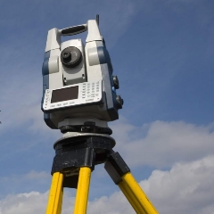
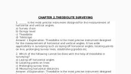
So far we have been measuring horizontal, angles by using a Compass with respect to meridian,, which is less accurate and also it is not possible to, measure vertical angles with a Compass., So when the objects are at a considerable, distance or situated at a considerable elevation or, depression ,it becomes necessary to measure horizontal, and vertical angles more precisely. So these, measurements are taken by an instrument known as a, theodolite., , THEODOLITE, , SURVEYING, , 2
Page 3 :
THEODOLITE SURVEYING, The system of surveying in which the angles are, measured with the help of a theodolite, is called, Theodolite surveying., , THEODOLITE SURVEYING, , 3
Page 4 :
THEODOLITE, The Theodolite is a most accurate surveying, instrument mainly used for :, • Measuring horizontal and vertical angles., • Locating points on a line., • Prolonging survey lines., • Finding difference of level., • Setting out grades, • Ranging curves, • Tacheometric Survey, THEODOLITE SURVEYING, , 4
Page 5 :
TRANSIT VERNIER THEODOLITE, , THEODOLITE, SURVEYING, THEODOLITE, SURVEYING, , 5
Page 6 :
TRANSIT VERNIER THEODOLITE, , Fig. Details if Upper & Lower Plates., , THEODOLITE, SURVEYING, THEODOLITE, SURVEYING, , 6
Page 7 :
TRANSIT VERNIER THEODOLITE, , THEODOLITE, SURVEYING, THEODOLITE, SURVEYING, , 7
Page 8 :
CLASSIFICATION OF THEODOLITES, Theodolites may be classified as ;, A., i) Transit Theodolite., ii) Non Transit Theodolite., B., i) Vernier Theodolites., ii) Micrometer Theodolites., THEODOLITE SURVEYING, , 8
Page 9 :
CLASSIFICATION OF THEODOLITES, A. Transit Theodolite: A theodolite is called a transit, theodolite when its telescope can be transited i.e, revolved through a complete revolution about its, horizontal axis in the vertical plane, whereas in aNon-Transit type, the telescope cannot be, transited. They are inferior in utility and have now, become obsolete., , THEODOLITE, , SURVEYING, , 9
Page 10 :
CLASSIFICATION OF THEODOLITES, B., Vernier Theodolite: For reading the graduated, circle if verniers are used ,the theodolite is called as a, Vernier Theodolite., , Whereas, if a micrometer is provided to read, the graduated circle the same is called as a, Micrometer Theodolite., Vernier type theodolites are commonly used ., , THEODOLITE SURVEYING, , 10
Page 11 :
SIZE OF THEODOLITE, A theodolite is designated by diameter of the, graduated circle on the lower plate., The common sizes are 8cm to 12 cm while 14 cm to, 25 cm instrument are used for triangulation work., Greater accuracy is achieved with larger, theodolites as they have bigger graduated circle with, larger divisions hence used where the survey works, require high degree of accuracy., , THEODOLITE SURVEYING, , 11
Page 12 :
DESCRIPTION OF A, TRANSIT VERNIER THEODOLITE, A Transit vernier theodolite essentially consist of the, following :, 1. Levelling Head., , 6. T- Frame., , 2. Lower Circular Plate., , 7. Plumb –bob., , 3. Upper Plate., , 8. Tripod Stand., , 4. Telescope., 5. Vernier Scale., THEODOLITE SURVEYING, , 12
Page 13 :
TERMS USED IN MANIPULATING A TRANSIT VERNIER THEODOLITE., , 1.Centering : Centering means setting the, theodolite exactly over an instrument- station, so that its vertical axis lies immediately above, the station- mark. It can be done by means of, plumb bob suspended from a small hook, attached to the vertical axis of the theodolite., The, centre, shifting, arrangement if provided with the instrument, helps in easy and rapid performance of the, centring., THEODOLITE SURVEYING, , 13
Page 14 :
TERMS USED IN MANIPULATING A, TRANSIT VERNIER THEODOLITE., 2. Transiting :, Transiting is also known as plunging or, reversing. It is the process of turning the, telescope about its horizontal axis through 1800, in the vertical plane thus bringing it upside, down and making it point , exactly in opposite, direction., , THEODOLITE SURVEYING, , 14
Page 15 :
TERMS USED IN MANIPULATING A, TRANSIT VERNIER THEODOLITE., 3. Swinging the telescope, It means turning the telescope about its, vertical axis in the horizontal plane., A swing is called right or left according as the, telescope is rotated clockwise or counter, clockwise., THEODOLITE SURVEYING, , 15
Page 16 :
TERMS USED IN MANIPULATING A, TRANSIT VERNIER THEODOLITE., 4. Face Left, If the vertical circle of the instrument is on, the left side of the observer while taking a, reading ,the position is called the face left and, the observation taken on the horizontal or, vertical circle in this position, is known as the, face left observation, THEODOLITE SURVEYING, , 16
Page 17 :
TERMS USED IN MANIPULATING A, TRANSIT VERNIER THEODOLITE., 5. Face Right, If the vertical circle of the instrument is on, the right side of the observer while taking a, reading ,the position is called the face right and, the observation taken on the horizontal or, vertical circle in this position, is known as the, face right observation., THEODOLITE SURVEYING, , 17
Page 18 :
TERMS USED IN MANIPULATING A, TRANSIT VERNIER THEODOLITE., 6. Changing Face, It is the operation of bringing the vertical, circle to the right of the observer ,if originally it, is to the left , and vice – versa., It is done in two steps; Firstly revolve the, telescope through 1800 in a vertical plane and, then rotate it through 1800 in the horizontal, plane i.e first transit the telescope and then, swing it through 1800., THEODOLITE SURVEYING, , 18
Page 19 :
TERMS USED IN MANIPULATING A, TRANSIT VERNIER THEODOLITE., 7. Line of Collimation, DIAPHRAGM, LINE OF, COLLIMATION, TELESCOPE, , It is also known as the line of sight .It is an, imaginary line joining the intersection of the, cross- hairs of the diaphragm to the optical, centre of the object- glass and its continuation., THEODOLITE SURVEYING, , 19
Page 20 :
TERMS USED IN MANIPULATING A, TRANSIT VERNIER THEODOLITE., 8. Axis of the telescope, OBJECT GLASS, AXIS OF THE TELESCOPE, ., TELESCOPE, , It is also known an imaginary line joining the, optical centre of the object- glass to the centre, of eye piece., THEODOLITE SURVEYING, , 20
Page 21 :
TERMS USED IN MANIPULATING A, TRANSIT VERNIER THEODOLITE., 9. Axis of the Level Tube, It is also called the bubble line., It is a straight line tangential to the longitudinal, curve of the level tube at the centre of the tube., It is horizontal when the bubble is in the centre., , THEODOLITE SURVEYING, , 21
Page 22 :
TERMS USED IN MANIPULATING A, TRANSIT VERNIER THEODOLITE., 10. Vertical Axis, It is the axis about which the telescope can be, rotated in the horizontal plane., 11. Horizontal Axis, It is the axis about which the telescope can be, rotated in the vertical plane., It is also called the trunion axis., THEODOLITE SURVEYING, , 22
Page 23 :
ADJUSTMENT OF A THEODOLITE, The adjustments of a theodolite are of two kinds :1. Permanent Adjustments., 2. Temporary Adjustments., 1), Permanent adjustments: The permanent, adjustments are made to establish the relationship, between the fundamental lines of the theodolite and ,, once made , they last for a long time. They are essential, for the accuracy of observations., , THEODOLITE SURVEYING, , 23
Page 24 :
ADJUSTMENT OF A THEODOLITE, 1. Permanent adjustments:, The permanent, adjustments in case of a transit theodolites are :i) Adjustment of Horizontal Plate Levels. The axis of, the plate levels must be perpendicular to the vertical, axis., ii) Collimation Adjustment. The line of collimation, should coincide with the axis of the telescope and, the axis of the objective slide and should be at right, angles to the horizontal axis., iii) Horizontal axis adjustment. The horizontal axis, must be perpendicular to the vertical axis., THEODOLITE SURVEYING, , 24
Page 25 :
ADJUSTMENT OF A THEODOLITE, 1., , Permanent adjustments (contd.):, , iv) Adjustment of Telescope Level or the Altitude Level, Plate Levels. The axis of the telescope levels or the, altitude level must be parallel to the line of, collimation., v) Vertical Circle Index Adjustment. The vertical, circle vernier must read zero when the line of, collimation is horizontal., , THEODOLITE SURVEYING, , 25
Page 26 :
ADJUSTMENT OF A THEODOLITE, 2., , Temporary Adjustment, The temporary adjustments are made at each set, up of the instrument before we start taking, observations with the instrument. There are three, temporary adjustments of a theodolite:i), , Centering., , ii), , Levelling., , iii), , Focussing., , THEODOLITE SURVEYING, , 26
Page 27 :
MEASUREMENT OF HORIZONTAL ANGLES:, There are three methods of measuring horizontal, angles:i), , Ordinary Method., , ii), , Repetition Method., , iii), , Reiteration Method., , THEODOLITE SURVEYING, , 27
Page 28 :
MEASUREMENT OF HORIZONTAL ANGLES:, i) Ordinary Method. To measure horizontal angle AOB:i) Set up the theodolite at station point O, A, and level it accurately., , B, , ii) Set the vernier A to the zero or 3600 of, the horizontal circle. Tighten the, upper clamp., iii) Loosen the lower clamp. Turn the, instrument and direct the telescope, towards A to bisect it accurately with, the use of, tangent screw. After, bisecting accurately check the reading, which must still read zero. Read the, vernier B and record both the, readings., , THEODOLITE SURVEYING, , o, HORIZONTAL ANGLE AOB, , 28
Page 29 :
MEASUREMENT OF HORIZONTAL ANGLES:, i) Ordinary Method. To measure horizontal angle AOB:iv) Loosen the upper clamp and turn the, telescope clockwise until line of sight, bisects point B on the right hand side., Then tighten the upper clamp and, bisect it accurately by turning its, tangent screw., v) Read both verniers. The reading of the, vernier a which was initially set at, zero gives the value of the angle AOB, directly and that of the other vernier, B by deducting 1800 .The mean of the, two vernier readings gives the value of, the required angle AOB., , THEODOLITE SURVEYING, , A, , B, , o, HORIZONTAL ANGLE AOB, , 29
Page 30 :
MEASUREMENT OF HORIZONTAL ANGLES:, i) Ordinary Method. To measure horizontal angle AOB:vi) Change the face of the instrument, and repeat the whole process. The, mean of the two vernier readings gives, the second value of the angle AOB, which should be approximately or, exactly equal to the previous value., vii) The mean of the two values of, angle AOB ,one with face left and, other with face right ,gives, required angle free from, instrumental errors., , THEODOLITE SURVEYING, , the, the, the, all, , A, , B, , o, HORIZONTAL ANGLE AOB, , 30
Page 31 :
MEASUREMENT OF HORIZONTAL ANGLES:, ii), , Repetition Method., This method is used for very accurate, work. In this method ,the same angle, is added several times mechanically, and the correct value of the angle is, obtained by dividing the accumulated, reading by the no. of repetitions., The No. of repetitions made usually in, this method is six, three with the face, left and three with the face right .In, this way ,angles can be measured to a, finer degree of accuracy than that, obtainable with the least count of the, vernier., , THEODOLITE SURVEYING, , A, , B, , o, HORIZONTAL ANGLE AOB, , 31
Page 32 :
MEASUREMENT OF HORIZONTAL ANGLES:, ii), , Repetition Method., To measure horizontal, repetitions:-, , angle, , by, , A, , B, , i) Set up the theodolite at starting point, O and level it accurately., ii) Measure The horizontal angle AOB., iii) Loosen the lower clamp and turn the, telescope clock – wise until the object, (A) is sighted again. Bisect B, accurately by using the upper tangent, screw. The verniers will now read the, twice the value of the angle now., , THEODOLITE SURVEYING, , o, HORIZONTAL ANGLE AOB, , 32
Page 33 :
MEASUREMENT OF HORIZONTAL ANGLES:, ii) Repetition Method contd..., iv) Repeat the process until the angle is, repeated the required number of times, (usually 3). Read again both verniers ., The final reading after n repetitions, should be approximately n X (angle)., Divide the sum, by the number of, repetitions and the result thus obtained, gives the correct value of the angle AOB., v), , Change the face of the instrument., Repeat exactly in the same manner and, find another value of the angle AOB. The, average of two, readings gives the, required precise value of the angle AOB., , THEODOLITE SURVEYING, , A, , B, , o, HORIZONTAL ANGLE AOB, , 33
Page 34 :
MEASUREMENT OF HORIZONTAL ANGLES:, iii) Reiteration Method., This method is another precise and, comparatively less tedious method, of measuring the horizontal angles., , A, , B, , It is generally preferred when, several angles are to be measured, at a particular station., This method consists in measuring, several angles successively and, finally closing the horizon at the, starting point. The final reading of, the vernier A should be same as its, initial reading., , THEODOLITE SURVEYING, , C, , o, , D, Reiteration Method, , 34
Page 35 :
MEASUREMENT OF HORIZONTAL ANGLES:, iii) Reiteration Method., …If not ,the discrepancy is equally, distributed, among all the, measured angles., , A, , B, , Procedure, Suppose it is required to measure, the angles AOB,BOC and COD., Then to measure these angles by, repetition method :, i) Set up the instrument over, station point, O and level it, accurately., , THEODOLITE SURVEYING, , C, , o, , D, Reiteration Method, , 35
Page 36 :
MEASUREMENT OF HORIZONTAL ANGLES:, iii) Reiteration Method., Procedure, ii) Direct the telescope towards, point A, which is known as, referring, object., Bisect, it, accurately and check the reading, of vernier as 0 or 3600 . Loosen the, lower clamp and turn the telescope, clockwise to sight point B exactly., Read the verniers again and The, mean reading will give the value of, angle AOB., iii), Similarly, bisect C & D, successively, read both verniers at-, , THEODOLITE SURVEYING, , A, , C, , B, , o, , D, Reiteration Method, , 36
Page 37 :
MEASUREMENT OF HORIZONTAL ANGLES:, iii) Reiteration Method (contd.)., Procedure. each bisection, find the, value of the angle BOC and COD., iv) Finally close the horizon by sighting, towards the referring object (point A)., , A, , B, , v) The vernier A should now read 3600., If not note down the error .This error, occurs due to slip etc., vi) If the error is small, it is equally, distributed among the several angles .If, large the readings should be discarded, and a new set of readings be taken., , C, , o, , D, Reiteration Method, , THEODOLITE SURVEYING, , 37
Page 38 :
MEASUREMENT OF VERTICAL ANGLES:, Vertical Angle : A vertical angle is an angle between the, inclined line of sight and the horizontal. It may be an, angle of elevation or depression according as the object is, above or below the horizontal plane., A, , AOB= α + β, , O, , A, B, , α, HORI. LINE, , β, O, , β, , HORI. LINE, Fig. b, , Fig.a, , AOB= α - β, , α, O, , HORI. LINE, β, α, , Fig. c, B, , B, , VERTICAL ANGLE, A, , THEODOLITE SURVEYING, , 38
Page 39 :
MEASUREMENT OF VERTICAL ANGLES:, To Measure the Vertical Angle of an object A at a station O:, (i) Set up the theodolite at station point O and level it, accurately with reference to the altitude bubble., (ii) Set the zero of vertical vernier exactly to the zero of the, vertical circle clamp and tangent screw., (iii) Bring the bubble of the altitude level in the central position, by using clip screw. The line of sight is thus made horizontal, and vernier still reads zero., (iv) Loosen the vertical circle clamp screw and direct the, telescope towards the object A and sight it exactly by using, the vertical circle tangent screw., , THEODOLITE SURVEYING, , 39
Page 40 :
MEASUREMENT OF VERTICAL ANGLES:, , (v) Read both verniers on the vertical circle, The mean of, the two vernier readings gives the value of the required, angle., (vi) Change the face of the instrument and repeat the, process. The mean of of the two vernier readings gives the, second value of the required angle., (vii) The average of the two values of the angles thus, obtained, is the required value of the angle free from, instrumental errors., , THEODOLITE SURVEYING, , 40
Page 41 :
MEASUREMENT OF VERTICAL ANGLES:, For measuring Vertical Angle between two points A &B, i) Sight A as before , and take the mean of the two vernier, readings at the vertical circle. Let it be α, ii) Similarly, sight B and take the mean of the two vernier, readings at the vertical circle. Let it be β, , iii) The sum or difference of these dings will give the value of the, vertical angle between A and B according as one of the points is, above and the other below the horizontal plane. or both points, are on the same side of the horizontal plane Fig b & c, , THEODOLITE SURVEYING, , 41
Page 42 :
READING MAGNETIC BEARING OF A LINE, To find the bearing of a line AB as shown in fig .below, i) Set up the instrument over A and level it accurately, ii) Set the vernier to the zero of the horizontal circle., N, , iii) Release the magnetic needle and loosen the, ….. lower clamp., iv) Rotate the instrument till magnetic needle, points to North. Now clamp the lower clamp with, the help of lower tangent screw .Bring the needle, exactly against the mark in order to bring it in, magnetic meridian. At this stage the line of sight, will also be in magnetic meridian., , B, , A, , Fig., Magnetic Bearing of a Line, , THEODOLITE SURVEYING, , 42
Page 43 :
READING MAGNETIC BEARING OF A LINE, Now loose the upper clamp and point the, telescope towards B .With the help of upper, tangent screw ,bisect B accurately and read both, the verniers .The mean of the two readings will be, N, recorded as magnetic bearing of line., iv), , B, , Change the face of the instrument, for accurate magnetic bearing of the, line and repeat .the mean of the two, values will give the correct bearing of, the line AB., v), , A, , Fig., Magnetic Bearing of a Line, , THEODOLITE SURVEYING, , 43
Page 44 :
PROLONGING A STRAIGHT A LINE, There are two methods of prolonging a given line such as AB, (1) Fore sight method ,and (2) Back Sight Method, (1)Fore Sight Method. As shown in the fig. below, A, , B, , C, , D, , Z, , i) Set up the theodolite at A and level it accurately .Bisect the, point b correctly. Establish a point C in the line beyond B, approximately by looking over the top of the telescope and, accurately by sighting through the telescope., ii) Shift the instrument to B ,take a fore sight on C and establish, a point D in line beyond C., Fig., iii) Repeat the process until the last point Z is reached., , THEODOLITE SURVEYING, , 44
Page 45 :
PROLONGING A STRAIGHT A LINE, (2) Back Sight Method. As shown in the fig. below, A, , B, , C, , D, , Z, , C’, D’, , i), , Set up the instrument at B and level it accurately ., , ii) Take a back sight on A., iii) Tighten the upper and lower clamps, transit the telescope, and establish a point C in the line beyond B., iv) Shift the theodolite to C ,back sight on B transit the telescope, and establish a point D in line beyond C. Repeat the process, until the last point ( Z) is established., , THEODOLITE SURVEYING, , 45
Page 46 :
PROLONGING A STRAIGHT A LINE, (2) Back Sight Method.(contd.) As shown in the fig. below, A, , B, , C, , D, , Z, , C’, D’, , Now if the instrument is in adjustment, the points, A,B,C,D and Z will be in one line, which is straight but if, it is not in adjustment i.e. line of collimation is not, perpendicular to the horizontal axis ,then C’, D’ and Z’, will not be in a straight line., , THEODOLITE SURVEYING, , 46
Page 47 :
PROLONGING A STRAIGHT A LINE, Double reversing Method, When the line is to be prolonged with high precision, or when the instrument is in imperfect adjustment, the, process of double sighting or double reversing, is used., Suppose the line AB is to be prolonged to a point Z., Procedure: As shown below:, C1, , A, , B, , C, , D1, , D, , Z, , C2, D2, Double Sighting / Reversing Method, , THEODOLITE SURVEYING, , 47
Page 48 :
PROLONGING A STRAIGHT A LINE, Double reversing Method, i), , Set up the theodolite at B and level it accurately., , ii) With the face of instrument left, back sight on A and, …. clamp both the upper and lower motions., iii) Transit the telescope and set a point C1 ahead in line., C1, , A, , B, , C, , C2, Double Sighting / Reversing Method, , THEODOLITE SURVEYING, , D1, , D, , Z, , D2, , 48
Page 49 :
PROLONGING A STRAIGHT A LINE, Double reversing Method (contd.), iv) Loosen the lower clamp ,revolve the telescope in the, horizontal plane and back sight on A .Bisect A exactly by, using the lower clamp and its tangent screw. Now the face of, instrument is right., v), Transit the telescope and establish a point C2 in line, beside the point C1., C1, D1, , A, , B, , C, , D, , Z, , C2, D2, Double Sighting / Reversing Method, , THEODOLITE SURVEYING, , 49
Page 50 :
PROLONGING A STRAIGHT A LINE, Double reversing Method (contd.), vi) The exact position of the true point C must be mid-way, …..between C1 and C2 ., vii) Measure C1 C2 and establish a point C exactly mid-way,, ….which lies on the true prolongation of AB., C1, , A, , B, , C, , C2, , D1, , D, , Z, , D2, , Fig. Double Sighting / Reversing Method, , THEODOLITE SURVEYING, , 50
Page 51 :
PROLONGING A STRAIGHT A LINE, Double reversing Method (contd.), viii) Shift the instrument to C, double sight on B ,establish the, …..point D1 and D2 and locate the true point D as before ., ix) Continue the process until the last point Z is established., , C1, , A, , B, , C, , C2, , D1, , D, , Z, , D2, , Double Sighting / Reversing Method, , THEODOLITE SURVEYING, , 51
Page 52 :
Method of traversing, , – Included angle method, – Deflection angle method, – Fast angle (or magnetic bearing method)
Page 53 :
Computation of latitude and departure, • Latitude of a line is the distances measured parallel, to the north south of the North-South direction, • Departure of the line is the distance measured, parallel to the east-west direction
Page 54 :
Computing latitude and departure
Page 55 :
Sources of errors in theodolite, • Instrumental errors, – Non adjustment of plate bubble, – Line of collimation not being, perpendicular to horizontal axis, – Horizontal axis not being perpendicular, to vertical axis, – Line of collimation not being parallel to, axis of telescope, – Eccentricity of inner and outer axes, – Graduation not being uniform, – Verniers being eccentric
Page 56 :
•, •, , . Personal errors, Natural errors, – High temperature causes error due to irregular refraction., – High winds cause vibration in the instrument, and this may lead to wrong, readings on verniers, , • Closing error
Page 57 :
Balancing of traverse, 1.Bowditch’s rule:, Total error is distributed in proportion to the lengths of the traverse legs.