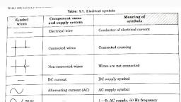
Notes of SE EEE, Electrical Machine 3 Phase Transformer - Study Material
Page 1 :
3 Phase Transformer 2021, Three Phase Transformer, Introduction:, Almost all the major power generation and distribution systems in the world, today are three-phase ac systems. Since three-phase systems play such an important, role in modern life, it is necessary to understand how transformers are used in them., Transformers for three-phase circuits can be constructed in two ways. One approach is, simply to take three single-phase transformers and connect them in a three-phase bank., An alternative approach is to make a three-phase transformer consisting of three sets of, windings wrapped on a common core. These two possible types of transformer, construction are shown in the figures below., The construction of a single three-phase transformer is the preferred practice, today, since it is lighter, smaller, cheaper, and slightly more efficient. The older, construction approach was to use three separate transformers. That approach had the, advantage that each unit in the bank could be replaced individually in the event of, trouble, but that does not outweigh the advantages of a combined three phase unit for, most applications. However, there are still a great many installations consisting of three, single-phase units in service., , Fig: A three-phase transformer bank composed of independent transformers., , RRG, , Page 1
Page 2 :
3 Phase Transformer 2021, , Fig: B three-phase transformer wound on a single three-legged core., , Three-Phase Transformer Connections:, A three-phase transformer consists of three transformers, either separate or, combined on one core. The primaries and secondary’s of any three-phase transformer, can be independently connected in either a Wye (Y) or a Delta (∆ ). This gives a total of, four possible connections for a three-phase transformer bank:, I. Wye(star)-Wye(star), 2. Delta-Delta, 3. (star)Wye-Delta, 4. Delta-Wye(star), , (Y-Y), (∆-∆), (Y -∆), (∆-Y), , The key to analyzing any three-phase transformer bank is to look at a single, transformer in the bank. Any single transformer in the bank behaves exactly like the, single-phase transformers already studied. The impedance, voltage regulation,, efficiency, and similar calculations for three-phase transformers are done on a perphase basis, using exactly the same techniques already developed for single- phase, transformers., The advantages and disadvantages of each type of three-phase transformer connection, are explained below along with the relevant connection diagrams., WYE-WYE CONNECTION:, The Y-Y connection details of three-phase transformers are shown in the figure, below., , RRG, , Page 2
Page 3 :
3 Phase Transformer 2021, , Figure (a): Star-Star(Y-Y) connection representation, , Figure (b): Star-Star(Y-Y) connection Phasor diagram, , Figure (c): Star-Star(Y-Y) connection wiring diagram, , In a Y-Y connection, the primary voltage on each phase of the transformer is given by, VØP = VLP / √3. The primary-phase voltage is related to the secondary-phase voltage by, the turns ratio of the transformer. The phase voltage on the secondary is then related to, the line voltage on the secondary by VLS = √3VØS . Therefore, overall the voltage ratio, ‘a’ of the transformer is then given by:, RRG, , Page 3
Page 4 :
3 Phase Transformer 2021, , Advantage:, This is useful and economical for low power high voltage transformers because, the phase voltage is 1/√3 times the line voltage. Hence the number of turns per phase, and the strength of insulation required would be less., , Disadvantages:, 1. If loads on the transformer circuit are unbalanced, then the voltages on the phases, of the transformer can become severely unbalanced., 2. Third-harmonic voltages can be large., When a three-phase set of voltages is applied to a Y - Y transformer, the voltages in any, phase will be 1200 apart from the voltages in any other phase. However, the thirdharmonic components of each of the three phases will be in phase with each other,, since there are three cycles in the third harmonic for each cycle of the fundamental, frequency. There will always be some third-harmonic components in a transformer, because of the nonlinearity of the core, and these components add up., The result is a very large third-harmonic component of voltage on top of the 50 or 6OHz fundamental voltage. This third-harmonic voltage can be larger than the, fundamental voltage itself., Both the unbalance problem and the third-harmonic problem can be solved using, one of the two following techniques:, 1. Solidly ground the neutrals of the transformers, especially the primary winding’s, , neutral. This connection permits the additive third-harmonic components to cause a, current flow in the neutral instead of building up large voltages. The neutral also, provides a return path for any current imbalances in the load., 2. Add a third (tertiary) winding connected in ∆ to the transformer bank. If a third, , ∆ connected winding is added to the transformer, then the third-harmonic components, of voltage in the ∆ will add up, causing a circulating current flow within the winding., This suppresses the third-harmonic components of voltage in the same manner as, grounding the transformer neutrals., RRG, , Page 4
Page 5 :
3 Phase Transformer 2021, The ∆ connected tertiary windings need not even be brought out of the transformer, case, but they often are used to supply lights and auxiliary power within the substation, where it is located. The tertiary windings must be large enough to handle the circulating, currents, so they are usually made about one- third the power rating of the two main, windings., One or the other of these correction techniques must be used any time a Y-Y, transformer is installed. In practice, very few Y-Y transformers are used, since the same, jobs can be done by one of the other types of three-phase transformers., DELTA-DELTA CONNECTION:, The ∆- ∆ connection details are shown in the figure below., One or the other of these correction techniques must be used any time a Y-Y, transformer is installed. In practice, very few Y-Y transformers are used, since the same, jobs can be done by one of the other types of three-phase transformers., , Figure (a): Delta-Delta (∆-∆) connection representation, , Figure (b): Delta-Delta (∆-∆) connection Phasor diagram, , RRG, , Page 5
Page 6 :
3 Phase Transformer 2021, , Figure (c): Delta-Delta (∆-∆) connection wiring diagram, , In a ∆- ∆ connection, VLP = VØP and VLS = VØS, so the relationship between primary, and secondary line voltages is given by:, , Advantages/Application:, • Transformers with this configuration are economical for high power low voltage, application since the number of turns required for a given line voltage are more, (since line voltage is same as phase voltage), • This transformer has no phase shift associated with it and no problems with, unbalanced loads or harmonics., • For the secondary voltage to be perfect sinusoidal the magnetizing currents must, contain third harmonic components. The Delta configuration provides a closed, path for the circulation of third harmonic components of current. Hence the flux, remains sinusoidal thus resulting in better sinusoidal voltages. The phase current, is lesser than the Line current (by 1/√3). Hence the conductor cross sectional area, can be smaller thus resulting in saving of conductor material., Disadvantages:, • Due to the non-availability of the Neutral point this configuration is not suitable, for three phase four wire systems, , RRG, , Page 6
Page 7 :
3 Phase Transformer 2021, WYE-DELTA CONNECTION:, The Y - ∆ connection details of three-phase transformers is shown in the figures below., In this connection, the primary line voltage is related to the primary phase voltage by, VLP = √3VØP while the secondary line voltage is equal to the secondary phase voltage, VLS = VØS . The voltage ratio of each phase is:, VØP / VØS = a, so the overall relationship between the line voltage on the primary side of the bank, and the line voltage on the secondary side of the bank is:, VLP / VLS = √3VØP / VØS = √3 a, , Figure (a): Wye-Delta (Y-∆) connection representation, , Figure (c): Wye -Delta (Y-∆) connection wiring diagram, , RRG, , Page 7
Page 8 :
3 Phase Transformer 2021, Advantages/Application:, • This connection is advantageous/economical for high power high voltage step, down power transformers. Primary in star configuration can be used for higher, voltage since line voltage is √3 times the phase voltage and thus the number of, turns required per phase will be lesser for a higher line voltage. The delta side, with lower line voltage (line voltage being equal to phase voltage) can be used as, secondary., • The neutral available in primary can be earthed to avoid distortion, • Hence transformers with this type of connection are used in the main receiving, end of a transmission line where a step down transformer is required., • The Y - ∆ connection has no problem with third-harmonic components in its, voltages, since they are consumed in a circulating current on the ∆ side., • This connection is also more stable with respect to unbalanced loads, since the ∆, partially redistributes any imbalance that occurs. i.e. Load side (secondary) large, unbalanced loads can be handled satisfactorily., Disadvantages:, • This arrangement has one problem. Because of this type of connection, the, secondary voltage is shifted 300 relative to the primary voltage of the transformer, which can be further positive shift or negative shift. The fact that a phase shift, has occurred can cause problems in paralleling the secondaries of two, transformer banks together. The phase angles of transformer secondaries must be, equal if they are to be paralleled, which means that attention must be paid to the, direction of the 300 phase shift occurring in each transformer bank to be, paralleled together., Star/Delta (Y/D) Connection (Alternate explanation for Phase grouping):, Star connection is formed on primary side by connecting together 1 suffixed terminals, with 2 suffixed terminals connected to appropriate lines. The delta is, formed by connecting c1a2, a1b2 and b1c2 with the lines connected to these junctions, being labeled as a, b and c respectively as shown in Fig. (a). The phasor diagram is, drawn in Fig. (b). It is seen from the phasor diagram on the delta side that the sum of, voltages around delta is zero. This is a must as otherwise closed delta would mean a, short circuit. It is also observed from the phasor diagram that phase a to neutral, voltage (equivalent star basis) on the delta side lags by – 30° to the phase-to-neutral, voltage on the star side. This is also the phase relationship between the respective line, to- line voltages. This connection, therefore, is known as – 30°-connection. Or YD1, RRG, , Page 8
Page 9 :
3 Phase Transformer 2021, representing 1O clock position. With this notation secondary Delta lags the primary star, by 300., , RRG, , Page 9
Page 10 :
3 Phase Transformer 2021, The + 30°-connection follows from the phasor diagram of Fig. (a) above with the, corresponding connection diagram shown in Fig. (b)., Delta/Star (D/Y) Connection (Alternate explanation for Phase grouping):, This connection is simply the interchange of primary and secondary roles in the, star/delta connection. One just interchanges capital and small letter suffixing in, the above figures .But what was the – 30°-connection will now be the + 30°connection and vice versa., DELTA-WYE CONNECTION:, ∆-Y connection details of three-phase transformers are shown in the figures below., In a ∆-Y connection, the primary line voltage is equal to the primary-phase voltage, VLP = VØP , while the secondary voltages are related by VLS = √3VØS . Therefore,, the line-to-line voltage ratio of this transformer connection is given by, :, , RRG, , Page 10
Page 11 :
3 Phase Transformer 2021, Figure (a): Delta - Wye (∆-Y) connection representation, , Advantages/Application:, • This connection is advantageous/economical for high power high voltage, step up power transformers. Primary in Delta configuration can be used for, lower voltage (line voltage being equal to phase voltage) And secondary in, Wye (star) configuration can be used for higher voltage since line voltage is, √3 times the phase voltage and thus the number of turns required per phase, will be lesser for a higher line voltage., • Hence transformers with this type of connection are used at the starting, (Generating station) end of a transmission line where a step up transformer is, required., Disadvantages:, This connection has the same disadvantages and the same phase shift as, the Y - ∆ transformer. The connection shown in the figure above makes the, secondary voltage differ the primary voltage by 30° as in Y -∆., The Open ∆ (or V-V) Connection:, In some situations a full transformer bank may not be used to accomplish three, phase transformation. For example, suppose that a ∆ - ∆ transformer bank, consisting of three separate transformers has a damaged phase which has to be, removed for repair., , RRG, , Page 11
Page 12 :
3 Phase Transformer 2021, , Figure: Third transformer (VBR) removed from the Three transformer Bank and, the corresponding Phasor diagram, Advantages/Application:, • This connection is advantageous/economical for high power high voltage, step up power transformers. Primary in Delta configuration can be used for, lower voltage (line voltage being equal to phase voltage) And secondary in, Wye (star) configuration can be used for higher voltage since line voltage is, √3 times the phase voltage and thus the number of turns required per, phase will be lesser for a higher line voltage., • Hence transformers with this type of connection are used at the starting, (Generating station) end of a transmission line where a step up transformer, is, required., , RRG, , Page 12
Page 13 :
3 Phase Transformer 2021, , Disadvantages:, This connection has the same disadvantages and the same phase shift as the Y - ∆, transformer. The connection shown in the figure above makes the secondary, voltage differ the primary voltage by 30° as in Y -∆., The Open ∆ (or V-V) Connection:, In some situations a full transformer bank may not be used to accomplish three, phase transformation. For example, suppose that a ∆ - ∆ transformer bank, consisting of three separate transformers has a damaged phase which has to be, removed for repair., The resulting configuration is known as open ∆ (or V-V) Connection and is shown, in the figure below., , Figure: Third transformer (VBR) removed from the Three transformer Bank and, the corresponding Phasor diagram, Advantages/Application:, • This connection is advantageous/economical for high power high voltage, step up power transformers. Primary in Delta configuration can be used for, lower voltage (line voltage being equal to phase voltage) And secondary in, Wye (star) configuration can be used for higher voltage since line voltage is, RRG, , Page 13
Page 14 :
3 Phase Transformer 2021, √3 times the phase voltage and thus the number of turns required per, phase will be lesser for a higher line voltage., • Hence transformers with this type of connection are used at the starting, (Generating station) end of a transmission line where a step up transformer, is required., , RRG, , Page 14
Page 15 :
3 Phase Transformer 2021, , Disadvantages:, This connection has the same disadvantages and the same phase shift, as the Y - ∆ transformer. The connection shown in the figure above, makes the secondary voltage differ the primary voltage by 30° as in Y ∆., The Open ∆ (or V-V) Connection:, In some situations a full transformer bank may not be used to, accomplish three phase transformation. For example, suppose that a, ∆ - ∆ transformer bank consisting of three separate transformers has, a damaged phase which has to be removed for repair., The resulting configuration is known as open ∆ (or V-V) Connection, and is shown in the figure below., , Figure: Third transformer (VBR) removed from the Three, transformer Bank andthe corresponding, Phasor diagram, If the open Delta primary is now excited from a balanced three phase, supply, then the voltage across the gap where the third transformer, used to be would exactly be the same voltage that would be present, if the third transformer were still there ., Thus, the open-delta connection lets a transformer bank work as a, RRG, , Page 15
Page 16 :
3 Phase Transformer 2021, three phase transformer with only two transformers, allowing some, reduced power flow to continue even with a damaged phase, removed., Power Delivered in Open Delta configuration:, How much apparent power can the bank supply with one of its three, transformers removed? At first, it seems that it could supply twothirds of its rated apparent power, since two-thirds of the, transformers are still present. Things are not that simple. To, understand what happens when a transformer is removed, let us see, the figures (a) and (b) below. Figure (a) shows ∆ - ∆ connection and, figure (b) shows V-V connection., , We know that the power output from a three phase system is √3 VLIL, Cos φ where Cos φ is the power factor. Hence in figure (a) ∆ - ∆, capacity = √3 VLIL Cos φ = √3 VL √3IPh Cos φ (since IL = √3IPh), = 3VL IPh Cos φ, But in figure (b) V-V capacity, IPh), , = √3 VLIL Cos φ = √𝟑 VL IPh Cos φ (since IL =, , Therefore V-V capacity / ∆ - ∆ capacity = √𝟑 VL IPh Cos φ / 𝟑 VL IPh Cos φ =, 1/√𝟑, = 0.577=57.7%, , RRG, , Page 16
Page 17 :
3 Phase Transformer 2021, , RRG, , Page 17
 Learn better on this topic