Notes of PUSHKAR's Classes PH, ELECTRONICS 『op-amp』 OP-AMP and Linear_IC_R.A.Gayakwad.pdf - Study Material
Page 27 :
·, · t ource is given by Equation (l-14)·, (c) The mput resistance seen from eac h mpu, s, ·, 06, 5, 25, Ril = Rri = 2/3acre = (2)(I00)( .3) = · k!l, ·, · b k · t0 the circuit from each of the two, The output resistance seen looking, ac m, output terminals is given by Equation (1-17):, Roi, , = Roi = 2.2 k!l, , EXAMPLE 1-2, Repeat Example 1-1 for the (a) dual-input, unbalanced-output and (b) single~, input, balanced-output differential amplifiers. ,, , SOLUTION (a) Since the component values remain unchanged and the biasing, arrangement is same, the IcQ and V CEQ values as well as input and output resistance, values for the dual-input, unbalanced-output configuration must be the same as, those for the dual-input, balanced-output configuration (see Table 1-1). Thus, , lcQ = 0.988 mA, VcEQ, , = 8.54 V, , R;1 =, , R;i = 5.06 kn, , Ro= 2.2 kn, , However, the voltage gain of the dual-input, unbalanced-output differential amplifier using Equation (1-21) is, Re, , Ad, , 2200, , = 2re = (2)(25.3) = 43 .48, , (b) Because the same biasing arrangement and same component values are used in, both configurations , the_results obtaine~ in Example 1-1 for the dual-input, balanced-out~ut config~ratton are also vahd for the single-input, balanced-output, configuration . That 1s,, , lcQ = 0.988 mA, VcEQ, , = 8.54 V, , Ad= 86.96, , = 5.06 kn, Roi = Roi = 2.2 kn, R;, , 26, , Differential and Cascode Amplifiers, , Chap. 1
Page 28 :
SOLUTION (a) In Exa, , l, input balan d, mp e_ l-1 we have determined the voltage gain of the dual86.96) and t~: -~utput differen~ial amplifier. Substituting this voltage gain (Ad =, g en values of mput voltages in Equation (1-11), we get, , _ Re, Vo -, , 7, , (Vin I -, , Vin 2), , ~, , = 86.96(50 mV -, , 20 .mV), , = 2.61 V pp, (b) Note that in Figure 1-2 the output voltage v is measured across the collec0, , ~or~. The~efore, to calculate the maximum peak-to-peak output voltage, we need, 0, etermme the voltage drop ~cross each collector resistor:, VRc, , = Rclc, , Substituting le= IeQ= 0.988 mA, we get (see Example 1-1), VRc, , = (2.2 k!l)(0.988 mA) =, , 2.17 V < VCE, , =, , 8.54 V, , This means that the maximum change 'in voltage across each collector resistor is, ±2.17 (ideally) or 4.34 V pp. In other words, the maximum peak-to-peak output, voltage without clipping is (2)(4.34) = 8.68 V pp., Remember that th~ maximum peak-to-peak output voltage without clipping, would have been 4.34 V pp if the same circuit were ::sed as the dual-input,, unbalanced-output differential amplifier., , SOLUTION (a) Substituting in Equations (1-34) and (1-4), we can determine the, values of fcQ and VeEQ, respectively:, lcQ, , =, , VEE - VaE =, 10 - 0.715, R9400 + 100 + 50/100, , 2RE, , + RE + {3mde, , = 0.977 mA, , Sec. 1-9, , Differential Amplifier with Swamping Resistors, , 27, ''
Page 29 :
VeEQ = Vee+ VsE - Relca, = to + 0.7l5 _ (2.2 kO)(0.977 mA), = 8.57 V1, (b) The ac emitter resistance, , _ 25 mV = ~ = 25.59 0, h mA 0.977, , rt -, , Therefore, substituting in Equation (1-35), the voltage gain is, 2200, = 17.52, Ad= Rk + rt - 100 + 25.59, Re, , _, , (c) The input resistance is given by Equation (1-36):, Ril = Rr1 = 2f3ac(Rk + rt), , = (2)(100)(100 + 25.59), = 25.12 kO, The output resistance is independent of RE values and therefore is the same as in, Example 1.1. rhat is,, R01 = R02 = 2.i kO, Comparing the voltage gain and the input resistance values .obtained in Examples, , 1-1 and 1-4..we can verify that the use of RE reduces the voltage gain but increases, the input resistance significantly., , 1-10 CONSTANT CURRENT BIAS, ", , / , ~, , f9, , ,,,.✓, , :-, , In the differential amplifiers discussed so far t~e combination of RE and VEE is, 4ised to set up the de emitter current. We can also use constant current bias, circuit to set up the de emitter current if desired. In fact, the constant current bias, circuit is better because it provides current stabilization and, in turn, assures a, stable operating point .for the differential amplifier. Figure 1-13 shows the dualinput, balanced-output differential amplifier using a resistive constant current, bias. Notice that the resistor RE is replaced by a constant current transistor (Q3), circuit. The de collector current in transistor Q.3 is established by resistors R , R2,, 1, and RE and can be determined as follows. Applying the voltage-divider rule, the, voltage at the base of_transistor Q3 (neglecting base loading effect) is ., -R2VEE, , 28, , Vs3, , = R1 +R2, , Vn, , = Vs3 - VsE3 = - RR2VEER - Vsn, 1+ 2, Differential and Cascode Amplifiers, , Chap. 1
Page 30 :
•, , -, , WiJW, , +Vee, , i, , lc3, , 03, , +, R,, , Vu, , +, Re, , -VEE, , ., , I, , ( Fi~re l-13 Dual-input, balanced-output differential amplifier, , ., , · usmg constant current bias., , Therefore,, l - VE3 - (-VEE), I E3 ·~, = 0 RE, Ia, , = VEE -, , [R2VEEl(R1, RE, , + R2)], , -, , V8 E3, , Because the two halves of the differential amplifier are symmetrical, each, ·, has half of the current Ic3• That is,, , hi =In= Ia= VEE - [R2VEE/(R1 + R2)] - VBE3, 2RE, 2, , (1-37), , The collector current Ia in transistor Q3 is fixed and must be invariant because no, signal is injected into either the emitter or: the base of Q3• Thus the transistor Q3 is, a source of constant emitter current for transistors Q1 and Q2 of the differential, amplifier (see Figure 1-13) ., .RecalUhai, in the analysis of the differential amplifier circuits with emitter, bias, we required that RE>> re. Besides supplying constant emitter current, the, constant current bias also provides a very higli source resistance since the ac, equivalent of the de current source is ideally an open circuit Therefore, all the, Sec. 1-10, , Constant Current Bias, , 29'
Page 31 :
,,-1, To the junction of, , - 1,, , 113, , V13, , +, , R, , 2, , o, and 02 emitters, , -, , 03, , +, , Vael -, , o,, , Vu, , +, Re, , D2, , i, , lu, , -VEE, , (a), , •Substrate, 8, , 9, , 10, , 11, , 12, , 13, , 3, , 2, , 14, , CA3086, , o,, , 7, , 6, , 5, , 4, (b), , To the junction of, 0 1 and 0 2 emitters, , lel ., V93, , -, , +, , (cl, , Figure 1-14 (a) Constant current bias with diode compensation for variations in VBE., (b) Functional diagram of, CA3086~, Constant current, bias using zener., , 30, Differential and Cascode Amplifiers, , Chap. 1
Page 32 :
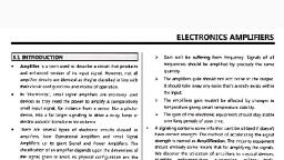
pe~orma~ce equations obtained for the differential amplifier configurations using, e~mtter bi~s are also .applicable to differential amplifiers with constant curr~nt, bias.}For ms~ance, the voltage-gain equation, (1-12), is valid for the differen_tial, am""ptifier_of Figure 1-2 as well as for that in Figure 1-13 with constant current bi~s., ~o improve the thermal stability of the constant current transistor Q3, teSIS~or ~i is re~laced by diodes Di and D2, as shown in Figure 1-14(a). The base _of Q3, is biased with the voltage divider containing components, R2, Di, and D2- Diodes, Di and D2 help to hold the emitter current h 3 constant even though the temperature changes. Note that Ii flows to the node at the base of Q3 and then divides into, path s Iv and 1B3:. If the temperature of Q3 increases, its base-emitter voltage Va£3, decreases. In s1hcon units, v8e decreases 2 mV ;oc, and in germanium units, VaE, decre~ses 1.6 mVl°C. This reduced V8EJ tends to raise the voltage drop across RE, and, m turn, current le3. However, the voltage drops across D, and D2 also, decrease, causing a greater portion of Ii to contribute to 10 , that is, causing ID to, increase. This causes 1B3 to decrease which prevents any significant increase, ', in /e3., For better performance, a transistor array such as CA3086 may be used in, Figure 1-14(a) as a constant current bias. Here an isolated transistor is used, and, needed diodes are formed by using transistors connected for diode operation,, work as well. The functional diagram of the CA3086, although discrete diodes, is shown in Figure 1-14(b)., The emitter current IEJ in Figure l-14(a) is determined as follows. Assuming, that the voltage drop across the diodes.is equal and denoting it by Vo, the voltage, at .the base of transistor Q3 is, , will, , VB3 =-Vee+ 2Vv, VE3, , =, , VB3 - VBEJ, , =, , -VEE+ 2Vv - VBE3, , VE3 - (-VeE) 2Vv - VBE3, R_E__, IE3 = -='--R--'E-- = __, , Assuming that the transistor Q3 h'1s the same characteristics as diodes Di and D2,, that is, if V0 = VBE3, then, IEJ = Vo, , RE, , (1-38), , Thus for a given value of RE the emitter current 1£3 depends on the voltage, drop across the diodes. But the voltage drop across the diodes is a function of the, current (Io) through them (according to the diode characteristic curve). However;, current lo is a part of current Ii, which is determined by the value of R2• This, means that we can change the value of /£3 by varying either the R2 or the RE [see, Equation (1-38)]., To design the constant current bias circuit of Figure 1-14(a), we will use the, following steps:, 1. Choose a desired IEJ value., 2• Assuming that Vo= 0.7 V, determine the value of Re using Equation (1-38)., Sec. 1-10, , Constant Current Bias ', , 31, , \, , I, \
Page 33 :
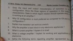
3. Assuming that Ii= IEJ and, from the following relation:, , v01 = Vm = 0.7 V, determine the value of R, , 2, , R2 =, , VEE - 1.4 V, , IEJ, , 0-39) ., , Often a zener diode is used in place of the diodes as shown in Figure, 1-14(c). Zeners are available over a wide range of voltages and can have, a matching temperature coefficient of voltage to those of-transistors. ·, Referring to the circuit of Figure 1-14(c), the voltage at the base of transi, stor, , Qds, , V83 =-VE E+ Vz, , Then the voltage a~ the emitter is, VE3, , = - VEE + Vz -, , VBE3, , Therefore, the current /E3 is, , Substituting and simplifying, we obtain, . _ Vz - VsE3, IE3 -, , RE, , (1-40), , The value of R2 should be selected so that Ii = 1.2/z" where / , is the minim, um, 2, current required to cause the zener diode to conduct in the reverse region, , that is,, to block the rated voltage Vz. The value of /z, is specified on the data sheet, of a, zener diode. Thus the value of R2 can be calculated using the equation, _ VEE - Vz, R2 (1-41), Ii, where Ii = 1.2/z,. The conclusion is q_uite simple: The zener diode is useful, for, maintaining a constant base voltage and, in tum, the constant emitter curren, t in a, constant current bias circuit., , f.f f CURRENT MIRROR, The circuit in which the output current is forced to equal the input curren, t is said, to be a current mirror circuit. Thus in a current mirror circuit the output curren, t is, a mirror image of the input current. The block diagram and the circui, t of the, current mirror are shown in Figure 1-15(cJ.) and (b), respectively. Once the, current, 12 is set up, the current /e3 is automatically established to be nearly, equal to Ji., The current mirror is a special case of constant current bias and therefore, can be, used to set up constant emitter currents 'in differential amplifier stages. Note, that, the current mirror circuit requires fewer cor.1ponents than constant curren, t bias, circuits. Because of its simplicity and ease of fabrication, the current, mirror, 32, , Differential and Cascade Amplifiers, , Chap. 1
Page 34 :
To the junction of, , o, and ~ emitters, , V13, , I IOU,a, , Current, mirror, , c..., , I, , - i- il2, , I link, , + R2, 1,ourc:e '" I link, , l93, , -, , Ie4, , 04, , l14, , +, , J 03, , Ia, , i!, , I, , l2, , v,E3 -, , r, , +, -V,e4, , lal, , (bl, , Fi~e 1_-15_ (a) Block diagram of current mirror. (b) Current, rrurror ctrcmt., circuit is most ~ommonly used in integrated amplifiers such as differential and, ·, operational amplifiers., Remember that for the proper operation of the circuit it is necessary to, construct a current mirror using a transistor array such as the CA3086 in which a, needed diode is formed by using an adjacent transistor [see Figure 1-15(b)]. When, used this way, the transistor array helps to achieve the required collector current, ., thermal stability in a current mirror circuit., Since Q3 and Q4 are identical transistors, their base-emitter voltages must~, the same, and their base and collector currents must also be approximately equal:, VBE3, , = VBE4, , Ia = /c4, , /B3 = /B4, , Summing currents at node, , VBJ,, , we obtain, , Ii = lc4 + I, = /c4 + 2/B4 = ]e3 + 2/B3, , = lc3 +, , 2(;::), , Ii= Ia (t +, Sec. 1-11, , current Mirror, , /3~), , (1-42), , 33, , '
Page 36 :
Ro, , Ro, Vo, , a,,, , -, , +, 02, , RG, , D,, , Figure 1-16 JFET differential amplifier with zener constant current bias., , '_1·(1, , EXAMPLE 1-6, , .~-,., , '', , Design a dual-input, balanced-output differential amplifier with a constant cur: \, ', rent bias (using diodes) to satisfy the following requirements:, Differential voltage gain Ad = 40 ± 10, Current suppli_ed by the c_onstant current bias circuit' = 4 mA, Supply voltages V.r ;., --~ :!; 10 V · ·, , SOLUTION First, we design a constant current bias circuit following the steps outlined in Section 1-10., 1. The desired value of emitter current /£3 = 4 mA (see Figure 1-17)., 2. We assume that the diodes D, and D2 are identical and that VDI = V02 = 0. 7 V., Rearranging Equation (1-38), we get, , Sec. 1-11, , Current Mirror, , 35
Page 37 :
+10 V, , 470 0, , 470 n, , Re, , +, , -, , Noninverting, input, , Re, , a,, , Inverting, input, , -l2, , 03, , R2 2 K, , D,, , Re, , 1so n, , D2, , .f, , le3, , 4mA, , · -10 V, , Figure 1-17 Differential·amplifier of Example 1-6., , Substituting yields, 7, R = 0. V = 175 0, E, , 4mA, , (use 150 fl), , 3. The value of R2 can be calculated using Equation (1-39):, Ri, , = vEE - 1.4 = 10 v - 1.4 v = 2. 15 kn, /£3, , 4 mA, , (use 2 kfi), , Equation (1-12)., Next, we determine the. value of the collector resistor Re using, Since /£3 · = 4 mA,, 25 mV, mA =12 .511, •, re=, and, A, =2m, h,= =In, 2, •, of the collector, Therefore, to obtain the differential gain of 40, the required value, resistor is, [from Equation (1-12)], Re = (Ad)re, , = (40)(12.5) = 500 n, 36, , (use 470 fi), , Differential and Cascode Amplifiers, , Chap. 1
Page 38 :
l, • -,,,,-,.••':J, , t?", , th, ;i~re ~-t 7 shows the dual-input, bal~nced-output differential amplifier wi, e~igne component values. Note that 'for proper operation of the amplifier circuit tbe use of a transiStor array such· as CA3086 is recommended ., ~",('n-..·~·~, , ,"''"v~. ,-:. ., .-;,· .·~, , ;:..JXAMPLE 1-7. ·., , w, , ', , ..., , ., , -, , ", , •, , ...., , :· '" ·, , . Design lhe ~e-input ; balanced-output differential amplifier sho~ in F~ _:, :::, ··:, l-18(a) to meet-,the following specifications:, !, ',I!(.,, , "., , '., , •, , ., , ., , J,, , J·,, ."), , l~put resi~ian~ Ri-:? 600 kO, Peak-t~p~ak output voltage swing :s5 V, . .Supply;:v9lfages V;<:,=·±10·-v . · .., ,. \., , "', , ·" _.,.;..-:C,--.,:.. ~-~-; ::., --~--,~-· ' ..:~~-~-1~,.,__..,_(_. _· .,~.;;.,.,_·:_ ..: .. -,,, ....·.•,, ' .: :,:,,· ·" · . ' '., , st6, SOL~O N Th~ circuit shown in Figure I-18(a) requires two Darlington tr~nsi r, pairs. We will choose the CA3018 or SK3542 silicon transistor array, which consists 0 ~ a ~arlington-connected transistor pair and two isolated transistors, as, shown m Figure 1-1 S(b). The isolated transistors can be used to form the current, mirror circuit. Remember that we need two transistor arrays. The following, specifications apply for each transistor in the CA3018 transistor array: /3dc = 100,, /3ac = 110, and VBE = 0.715 V. The desired input resistance for the single-input,, balanced-output configuration is 600 kn. Therefore, using Equation (1-30), for the, Darlington pair, R;, , = 2f3acr(2re3), , where f3acr = total current gain of the Darlington pair, =, , (110)(110) = 12.1 k, , 2re3 = ac emitter resistance of the Darlington pair Q3Q4, Substituting yields, 600 kn = (2)(12.1 k)(2re3), , = QsQ6, , Therefore, the ac emitter resistance of transistor Q3( = Qs) is, YeJ, , 600 kn, , = 48.2 k = 12.4 .n, , But, 25 mV, , Ye3, , = IE3 mA, , Therefore,, IEJ, , =, , 25 mV, 12, , .4 n = 2.02 mA, , · Let us choose IEJ = Jes = 2 mA. This means t~at the ~urr_ent mirror circuit must, supply 21£3 = 4 mA. To form the current mirror circmt we can use isolated, Sec. 1•11, , Current Mirror, , 37, , I, 1;, 11
Page 39 :
+10 V, , Re, , Re, Vo, , -, , +, , Non inverting, input, , 05, , 03, , Inverting, input, , -10 V, , (al, , 12, , 11, , 7, , 4, Case and substrate, , (bl, , Figure 1-18 (a) Darlington-pair differential amplifier of Example, 1-7. (b) CA3018 transistor array (metal can)., 38, Differential and Cascade Amplifiers, , Chap. 1
Page 40 :
---------- transistors in one of th,, lated by using Equatio~, , :~~4f, , ---, , A30I8s, and the value of R2 needed can be calcu-, , Substituting, we obtain, R2 ==, , !Q V - 0.715 V, 4 mA, , ==, , 2.32 kfl, , (use 2.2 k!l), , Assume that the volta d, peak output voltage ge_ rop across collector resistor Re determines the peak-toFigure l-18(a) is ~wmg. !he expected output voltage swing in the circuit of, 5, across each collector r P~- Si~ce the output is "differential," the voltage drop, stst0r ts 2.5 V, V. Substituting, == e, PP or± 1.25 V. In other words, Rclc = 1.25, 1, ' c 2 mA, we get, Re = 625 fl, (use 620 fl), Thus for the single-in t b, ·, we need th ~ II . pu ' a1anced-output differential amplifier of Figure 1-18(, a),, e 10 owmg components:, , Two transistor arrays: CA3018, Re= 620 fl, R2 = 2.2 kfl, 1-12 CASCADED DIFFERENTIAL AMPLIFIER STAGES, , Having gone through an analysis of the differential amplifier circuit configurations, let us see how differential amplifiers can be cascaded (connected in series)., Figure 1-19 shows a typical two-stage differential amplifier. The first stage is a, dual-input, balanced-output differential amplifier. The second stage is another, differential amplifier driven by the output of the first differential amplifier. A, single-ended (unbalanced) output is taken from this second stage. Both stages use, the emitter biasing technique (the combination of RE and VEE) to set up the emitter, currents in the differential pairs., In many cases the matching of transistors as well as resistor values is essential for proper operation of the differential stages. For this reason the use of, transistor arrays such as CA3086 (or LM3146) is recommended. A transistor, array such as CA3086 provides. in~erent advantages unique to integrated circuits:, electrical and thermal matching, compactness, and ease of physical handling., , EXAMPLE 1-8, -., For the cascaded differential amplifier shown in Figure 1-19, determine:, (a) The collector current and collector-to-emitter voltage for each transistor., Sec. 1_12, , Cascaded Differential Amplifier Stages, , 39
Page 41 :
(b) The overall voltage gain., , ., ., .(c) The input resistance., ·s used (for which /3dc = 100 typical,, (d) The output resistance., 86, . Assume that the transistor array CA30. ~·agram of the CA3086 is shown in, /Joe = 100, and Vs£= 0)15 V). The pm 1, Figure 1-14(b)., , Vee, , +10 V, , Re4, Re,, , Re2, , 2.2 k!l, , 2.2 k!l, , Re3, , 1.2 k!l, , 1.2 k!l, 9.32 V, Yo, , 7.83 V, , I, , 03, , l, , 04, , Yo1, NoninYerting, input, , R~, 100n, , R~, 100n, , -0.715 V, , Yid, , ., , 7.12 V, , t, , t, , 2le3, , 2Ie1, , Inverting, input, , Rei, , 4.7 k!l, , Re2, , -Vee, , 15 k!l, , -10 V, , Figure 1-19 Cascaded differential amplifier of Example 1-8., , SOLUTION, (a) To determine the collector current and collector-to-emitter voltage of transistors Q1 and Q2, we assume that the inverting and noninverting inputs are, grounded. The collector current (le== le) in Q, and Q2 is obtained by substituting, , the known •values in Equation (1-2):, , VEE - VsE, hi = 2RE1 + RiJ/3dc, , That is, lc1 = IC2, 40, , 10 - 0.715, = 2(4700) + 0 = 0.988 mA, , = 0.988 mA., Differential and Cascade Amplifiers, , Chap. 1
Page 43 :
where, . R;2, , = input resistance of the second stage, = 2/3acCre3.+ Ri), = (200)(143.94) = 28J9 k!l, 2.2 k!l, , Adi =, , II 28. 79 k!l = 80.78, 25.3, , . d · t unbalanced-output differential amplifier with, h. h ., The second stage 1s a ua1-mpu •, swamping resistor RE, the voltage gain of w ic is, =1. 2 kn=4.17, Rc4, Vo, At12 = Vol = 2(RE + fe4) 287 .88, Hence the overall voltage gain is, Ad= (Ad1)(At12) = (80.78)(4.17) = 336.85, Thus we can obtain a higher voltage gain by cascading differential amplifier, 'fi · h, ., ., stages., (c) The input resistance of the cascaded differential amph er is t e same as the, input resistance of the first stage, that is,, Ril = 2/3ac(rei) = (200)(25.3) = 5.06 k!l, (d) The output resistance of the cascaded differential amplifier is the same as the, output resistance of the last stage. Hence, using Equation (1-17),, Roi, , = Rc4 = 1.2 k!l, , 1-13 LEVEL TRANSLATOR, , · From the results of the cascaded differential amplifier of Example 1-8, the following observations can be made:, 1. Because of the direct coupling, the de level at the emitters rises from, stage to stage. This increase in de level tends to shift the operating point of the, succeeding stages and, therefore, limits the output voltage swing and may even, distort the output signal. For example, in the circuit of Figure 1-19, the voltage at, the emitters of Q1 and Q2 of the first stage is -0.715, whereas that at the emitters, of Q3 and Q4 of the second stage is 7. 12 V., If used as a single stage, the voltage at the emitters of Q3 and Q4 would have, been -0.715 V. Thus the increase in the emitter voltage of the second stage and in, tum the change in its operating point are due to the cascading of differential, amplifier stages., 2. The voltage at the output terminal of the second stage in Figure 1-19 is, well above ground (0 V). This de level is undesirable because it tends to limit the, peak-to-peak output voltage swing without distortion and also contributes to the, error in the de output signal., 42, , Differential and Cascode Amplifiers, , Chap. 1
Page 44 :
Therefore, in Figure 1-19 a, de level at the second sta d final stage should be included to shift the output, referred to as a /eve[ 1 ge own to about zero volts to ground. Such a stage is, . l, ransIator or h:r., .fl, s t.,ter. Thus, in the cascaded different1a, ampII er, to shift the outp t d, followed by a level translatu ~ le~el down to zero volts, the final stage must be, tor circuits, an emitter foll or circ~it. Although there are a variety of level transla[see Figure I-20(a)]. Th ower with a voltage divider is the simplest among them, work into the voltage_;;i~iut 0 ~ the second differential stage in Figure 1-19 can, e_mttter-follower stage of Figure I-20(a). Thus a, positive 9.32 at the out, put temunal (Ve◄) of the second stage in Figure 1-19 can, ·, , Input, , -----.J, Output, , -VEE, , J, , (a), , +Vee, , +Vee, , Input .,._- ~, , Input, , 05, , R, , 0 V de, , /, Output, , ~, D,, , (b), , J, , Output, R2, Os, , i, , (c), , Figure 1-20 Level translator circuits. (a) Emitter follower with, voltage divider. (b) Emitter follower with constant current bias., (c) Emitter follower with current mirror., Sec. 1-13, , Level Translator, , 43
Page 45 :
of corn, . t'1 n of R, and R2 with proper selection, th, tter follower either with a dii ;·, produce zero volts at eO:"~ ~ by using an emi, sh e, tame . ror instead of the voltage divider ' as own, nents. Better results are a curr, ent mir, t bias or, constant, t, res ectively. Note that the resistive or zener, ~on~tan curren, l, wer in forming a leve transl a., m Figure_ l-20(b)alandb(c), dpw1'th the emitter follo, current bias can so e use, tor., , EXAMPLE 1-9, re l-20(b) for the cascaded, Design a level translator circuit as shown in Figu, differential amplifier in Figure 1-19. ., , ector of Q4 down to zero volts at the, SOLUTION We need to shift 9.32 Vat the coll, owing the design steps listed in, collector of Q6 [see Figures 1-19 and l-20(b)]. Foll, ent bias circuit and -then select, Section I-IO, we first design the diode constant curr, age at the collector of Q6 is zero volts., an appropriate value for R so that the volt, refore, using Equation (1-38), the, Let us choose h 6 = 3 mA and Vs= ± 10 V. The, value of RE is, Vv, RE= h6, , -_ = 233.3 !l, = _Q:2, 3 mA, , (use 27On ), , 9) yields, Substituting the known values in Equation (1-3, R _ VEE - 1.4 V = 10 V -mA1.4 V -_ 2.87 kn, h, 23, 6, , (use 2. 7 kn), , emitter of Q5 is, Assuming that VaE5 = 0. 7 V, 'the voltage at the, VE5 = Va5 - VaE5 = 9.32 - 0.7 = 8.62 V, zero and h 5, Sine~ the voltage at_ the collector Q6 is to be, reqmred value of R 1s, R - VE5 - 8.62 V - 2, - h - 3 mA .,... ,87 k!l, , = Jc6 = 3 mA the, ', , (use a 3-kn potentiometer), , 5, , ents are, Thus the desired level translator circuit compon, R = 3-kn·potentiometer, RE = 210 n, , = 2.7 kn, D,, D2, Q5, and Q6 = CA3086, Rz, , 44, , Differential and Cascode Amplifiers, , Chap. 1
Page 46 :
- - ~- ~~-,..=". --:--- - '------."""-..~ •·, , ~, , ~, , :., I, , MPtil-10 . . . ., , ., , ,.. ., , . -·, , .., , . ~o_r.the cascaded differential amplifier of Figure 1-21, deiermfoe:, (a) The lcQ ~nd VCEQ for each transistor., {b) Tbe overall voltage gain., , ~ IOO, _, (c) The maxinium peak-to-peak output voltage swing. ., that the CA3086 transistor array is used for which f3ac - /3dc, (Assume, and VsE == 0.715 V.), t ., , ., , ., , SOLUTION The circuit in Figure 1-21 consists of three stages:, 1. Dual-input, balanced-output differential amplifier, 2. Dual-input, unbalanced-output differential amplifier, 3. Level translator circuit, , +Vee=lOV, , Re2, 2.7 kn, , Re,, 2.7 kn, , Res, 1.5 kn, , 6.84 V..____, , _,, , 4.3 V, , +, , +, , 3.59 V, , -0.715 V, , - -, , 4.22 mA, , i, , J, , 4.22 mA, , 4.22 mA, , t'mAf, , +, , 2.2 kn, R2, , -, , VEE =-10 V, , Figure 1-21 Cascaded differential amplifier of Example 1-10., , Sec. 1-13, , Level Translator, , 45
Page 48 :
(b) The ac emitter resistances are, ==, , rel, , ==, , re6, , 25 mV == 25 mV h,, 2.1'1 mA - 11.85 fl, , 25 mV, es - /£8 =, and input resistance of the, d, secon stage, r, , _, , 25 mV, 4.22 mA = 5.92 fl, ., is, , R,-i = 2/3acre6 = (200)(11.85), Therefore, the voltage gain 0 f th fi, ., e rst stage 1s, Adi, , = 2.37 kfl, , = RcdlR,1 = 2. 7 kflll2.37 kfl -, , - 106 .5, , 11.85, , re,, , The input resistance of th th' d, e tr stage (looking into the base of Q8) is, , R,3 == /3ac(res + RES) = (100)(5.92 fl + 1.5 kfl), Hence the voltage gain of the second stage is, Ac12 = Rc6IIR;3, , = 150.6 kfl, , = 1.5 kf!li 150.6 kfl _, , - 62 ·66, , (2)(11.85) f!, , 2re6, , The voltage gain of the third stage is, Ad3, , =1, , Thus the overall gain of the circuit in. Figure 1-21 is, Ad, , = (Ad1)(Ac12)(Ad3) = (106.5)(62.66)(1) = 6673.3, , (c) The third stage in Figure 1-21 is the level translator circuit and, in addition, the, voltage gain of this stage is unity. Therefore, the maximum peak-to-peak output, voltage swing is determined by the ·second stage, specifically the voltage drop, across the collector resistor Rc6. The voltage drop across collector resistor Rc6 is, VRc6, , =, , (1.5 kfl)(2. l l mA), , =, , 3.17 V, , Hence the maximum peak-to-peak output voltage swing is, v0 =, , ±3.17 V or 6.34 V pp, , 1-14 CASCODE OR CE-CB CONFIGURATION, , Each of the small-signal amplifier configurations, common emitter (CE), common, base (CB), and common collector (CC), has some unique advantages as well as, drawbacks. The specific property of the amplifier configuration can be enhanced,, a specific drawback can be removed, or a special feature can be added by connecting two configurations. Because there are three configurations, we can form nine, , Sec. 1-14, , Casce>de or CE-CB Configuration, , 47
Page 49 :
r, possible combinations each having two configurations. But, unfort~~at~ly 0 ~ of, 0, these nine possible c~mbinations, some do not improve the amp 1 er s, ~, mance in any way and are, therefore, not practical. The moS t common Y use, combinational configurations are the following:, , te ·, , 1. Common collector-common collector (CC-CC) connection, 2. Common collector-common emitter (CC-CE) connection, 3. Common collector-common base (CC-CB) connection, 4. Common emitter-common emitter (CE-CE) connection, 5. Common emitter-common base (CE-CB) connection, , The Darlington· pair can be used to obtai_n ~ CC-:CC configuration. The, Darlington pair is a composite two-transistor device m which _the c?llec_tors of two, transistors are tied together and the base of the second transistor 1s dnven by the, emitter of the first. The principal advantages of this configuration are th~t the, input resistance and the current gain are increased by a factor f3 over those m the, standard CC configuration., Another example of the CC-CC configuration is the double follower circuit, in which complementary transistors are connected in the CC-CC configuration., The main features of this circuit are that the output voltage is equal to the input, voltage and that a very high current gain is provided., To obtain the CC-CE configuration, we can use the Darlington pair in place, of a single transistor in CE configuration. In this configuration the current gain, and the input resistance are improved by a factor (3 over that of the CE amplifier., Note that these increases are achieved at the sacrifice of a slight decrease in, voltage gain .., The single-input, unbalanced-output differential amplifier of Figure 1-1 Outilizes the CC-CB configuration. This configuration basically has the same input, characteristics as the CC amplifier and the same output characteristics as the CB, amplifier., If the main objective is to obtain a very large voltage or power gain, we can, use the CE-CE configuration. The complementary pair can also be utilized in, forming the CE-CE configuration. Recall that in forming the dual-input, balanced, output differential amplifier, we also have to use two symmetrical CE sections, (see Figure 1-2). Thus the CE-CE is the most commonly used configuration., The CE-CB configuration (usually referred to as the cascade amplifier) is, shown in Figure 1-22. Note that the CE and CB stages are direc.t-coupled. This, configuration, of luurse, has basically the same input characteristics as the CE, amplifier and the same output characteristics as the CB amplifier. More specifically, it has high output resistance and is inherently more stable. The high output, resistance attainable is useful in achieving large amounts of voltage gain. Also, in, this configuration no high-frequency feedback occurs from the output back to the, input, and the input Miller capacitance effeclis at a minimum because the voltage, gain of the CE configuration is very low . Therefore, a CE-CB configuration is, inherently more stable and hence ideally suited for high-frequency applications., , j:, , I, , I, , I, \, , 48, , Differential and Cascode Amplifie rs, , Chap. 1
Page 50 :
+Vee, , Re, , R3, , co, , r---o, , Va2, , c~J, , (CB), , R2, VR1, , Vo, , J, , 02, , a,, , C;, , (CE), , Ve,, , R,, Re, , Cs,, , Figure 1-22 Cascode amplifier., , 1-14. 1 DC Analysis, , In the cascode amplifier of Figure 1-22 , R1, R and R form a bias netwo, 2, rk for Qi, 3, and Q2; Cs, and Cs2 provide ac signal ground paths from the Q emitt, er and Q2, 1, base , respectively ; and C; is the coupling capacitor. For the proper, operation of, the circuit we require that transistors Q1 and Q2 be identical. Keep, in mind that, for de conditions all capacitors are assumed to be open-circuit., Becau se of identical transistors and the direct coupling between the CE-C, B, stages ,, h, , 1, , = h2 or le, = la and, , /81, , = /82, , This mean s that we need to determine the emitter current of Qi only. Applying, the voltage-divider rule, we get, , R1Vcc, , (1-45), , Therefore ,, , Sec. 1-14, , Cascode or CE-CB Configuration, , 49
Page 51 :
Substituting yields, , h,, , [(R1)Vccl(R1, =, , + R2 + R3)], , - VB£1, , (1-46), , RE, , Thus once we know the emitter current of Q1 we can determine all the currents in, and voltages at the three transistor terminals for Q1 and Q 2 if desired., 1-14.2 AC Analysis, , The small-'signal T-equivalent circuit for the cascode amplifier is shown in Figure, 1-23. Since we are considering only the low-frequency performance, we assume, all capacitors as short-circuit elements. We will determine the low-frequency,, small-signal properties of the cascode circuit: the voltage gain, current gain, and, input resistance., Note that, in Figure 1-23, Rs = RdlR2 ; r e 1 r ei since h1 h2; and V o 1 is the, output voltage of the CE stage. Since Q1 and Q2 are identical transistors, /3dc 1 =, /3dc 2 and f3ac 1 = f3ac 2; therefore, we will omit subscripts in the calculations that, follow., , =, , =, , For the input circuit in Figure 1-23,, , 1-14.2(a) Voltage gain., Vjn, , V ol, , Since i~2 = ic1 and ic1, the CE stage is, , = (re1)Ue1) since Rs >>, = -(re2)(iti}, , r el, , =ie1, implies that ie2 =ie1. Therefore, the voltage gain A 111 of, Since r e l =, , (1-47), , Ye2, , The output voltage, , - j in, , jb1, , --, , B,, , c,, , -, , E2, , ic2, , C2, , jcl, , jAB, , i, , Rs, , i,,, , i, , jo, , +, r ,1, , t, , +, , vo,, , t, i,2, , r,2, , +, , +, , ic2, , Re, , e,, Figure 1-23 Small-signal T-equi'!alent circuit of cascode amplifier., 50, , Differential and Cascode Amplifiers, , Chap. 1
Page 55 :
SUMMARY, , ., , ., , ., , nsists of two symmetrical commo~-emitter sec-, , t. The differential amphfier co ·r . the difference between two mput signals, , tions and is capable _of amph ymtfy ac as well as de input signals because ii, The differential amphfier can amp 1, employs direct coupling. ., ., lifier configurations:, 2. There are four types of differential amp, (a) The dual input, balanced output, · (b) The dual input, unbalanced output, (c) The single input, balanced output, (d) The single input unbalanced output, •, ., . ', defined according to the number of mput signals used, These configurat1ons are, •, h, nfi, •, and the way output is measured. ~~en, use ~wo mputs, t e co guration ~s, said to be dual input; otherwise, it ts a Smgle •~pu~. If the output voltage 1s, measured between two collectors, the configuration ts refei:ed to as a balanced, output. On the other hand, if the output _is measured at either collector with, r~spect to ground, the configuration is said to b~ unbalanced ~utput., 3. For proper operation of. the differe';}tial ampl~er, a ~rans1stor array and, matched components must be used. The ~ifferenttaJ amplifier can be biased by, using emitter bias (a combination of RE and VEE), constant current bias, or, current mirror techniques., 4. In a cascaded differential amplifier, the output of the first stage is used as an, input for the second stage, the output of the second stage is applied ·as an input, to the third stage, and so on. Because of direct coupling between the stages,, the operating point of succeeding stages changes., 5. Generally, in a cascaded differential amplifier, the last dual-input, unbalancedoutput stage is followed by a level translator. The function of the level translator is to make the de voltage at the output terminal zero., 6. The cascode amplifier is composed of direct-coupled common-emitter and, common-base configuratio'ns. It provides a large amount of voltage gain at, higher frequencies., , W:, , QUESTIONS, , 1-1. What is a differential amplifier?, 1-2. What are the four differential :amplifier configurations? Which one is not, commonly used, and why?, 1-3. What does the term "balanced output" mean?, 1-4. What is the main advantage of constant current bias over emitter bias?, 1-S. Explain the differences between constant current bias and current mirror., 1-6. What is a level translator circuit? Why is it used with the cascaded differential amplifier?, ·, 1·7• What is a cascode amplifier? List the characteristics, of the cascode amplifier., 54, , Differential and Cascade Amplifiers, , Chap. 1
Page 56 :
PROBLEMS, l-L An emitter-biased dual-input, balanced-output differential amplifier has the, following specifications: IVeel = 1-VEEI = 10 V, Re, = Rei = 2.7 k.O, a nd, RE= 3.9 k.O; the transistor array is CA3086 with /3ac = /3dc = 100 a nd Vs£=, 0~715 V. Calculate:, (a) The operating current and voltage values for each transistor., (b) The voltage gain., (c) The input resistance of the circuit., ., l-2. Repeat Problem 1-1 for the dual-input, unbalanced-output differential amplifier., 1-3. Repeat Problem 1-1 with RE= 5.6 k.O., 1-4. Repeat Problem 1-1 with Re, =Rei= 5.6 k!l., 1-5. Repeat Problem 1-3 for the single-input, balanced-output configuration., 1-6. Repeat Problem 1-4 for the dual-input, unbalanced-output configuration., 1-7. Repeat Problem 1-4 for the single-input, balanced-output configuration., 1-8. For the dual-input, balanced-output differential amplifier of Problem I- I:, (a) Draw the output voltage waveform if Vin 1 = 5 mV pp and Vin 2 = 2 mV PP, at I kHz. Assume that the collector C, is negative with respect to, collector C2 (see Figure 1-2)., (b) Determine the maximum peak-to-peak output voltage swing without, clipping., 1-9. Repeat Problem 1-8 for the dual-input, unbalanced-output configuration., 1-10. Repeat Problem 1-8 if 180-0 resistors R~are placed externally in series with, each emitter (see Figure l,-12)., 1-11. The JFET dual-input balanced-output differential amplifier uses the zener, constant current bias. Determine the voltage gain and the input resistance, of the amplifier if Ro= 3.9 k.O, RG = 1 MO, gm= 4000 µs, and Vs= ± 9 V. ·, 1-12. For the modified current mirror circuit shown in Figure 1-24, determine, the emitter current in transistor Q3• Assume that the CA3086 transistor ·, array is used. For each transistor in the array, /3dc = f3ac = 100 and Vs£ =, 0.715 V., 1-13. Referring to the circuit of Figure 1-25, determine:, (a) The current through collector resistor Re., (b) The collector current in each transistor., Assume that the CA3086 transistor array is used., 1-14. For the single-input, balanced-output differential amplifier shown in Figure, 1-26, determine:, (a) The operating PQint values (fcQ and VCEQ),, (b) The voltage gain., (c) The input resistance., (d) The maximum peak-to-peak output voltage., Assume that /3ac = /3dc = 100, Vs£ = VDI = 0. 715 V, Vz = 6.2 V, and ]z, =, · 41 mA., Chap. 1, , Questions, , 55, , .A
Page 57 :
-, , +10 V, , Re, , 2.2 kn, , 4.7 kfl, , -10 V, , Figure 1-24 Modified current mirror circuit of Problem 1-12., , +10 V, Re, , 1kU, ~, , r, , 5.6kU, , -10V, , Figrae 1-25 Modified current mirror circuit of Problem 1-13., , 1-15. For the cascaded differential amplifier of Figure 1-27, determine:, (a) The de conditions for each stage., (b) The overall voltage gain., (c) The maximum peak-to-peak voltage swing:, Assume that the CA3086 transistor array is used., 56, , Diffe:rential and Cascode Amplifiers, , Chap. 1
Page 58 :
+10V, , Re, , 4.7 kn, , 4.7kn, , Re, , R2, , 68n, , +, , +, 1N914, , 03, , Vae -, , 01, , Re, , +, 1N4735, , 2.7 kn, , 02, , -10 V, , Figure 1-26 Differential amplifier of Problem 1-14., +8 V, , 1.8 kO, 1.8 kn, , 5.6 kU, , 5.6 kfl, , vo, 03, , +, , 18011, , 02, , o., 100 n, , 3.3 kn, , 4.7 kn, , - 8\t, , Figure 1-27 Cascaded differential amplifier of Problem 1-15., , J
Page 59 :
1-16., 1-17., 1-18., 1-19., 1-20., , Repeat Problem 1-15 for the circuit shown in Figure 1-28., Repeat Problem 1-15 for the circuit shown in Figure 1-29., Repeat Problem l-15 for the circuit shown in Figure l-30., Repeat Problem 1-15 for the circuit shown in Figure l-31., Repeat Problem l-15 for the circuit shown in Figure 1-32. Assume that the, input common-mode voltage VcM is 3.5 V., 1-21. Repeat Problem 1-15 for the circuit shown in Figure l-33., 1-22. For the cascode amplifier shown in Figure 1-22, determine:, (a) The de conditions for each transistor., (b) The overall voltage gain., (c) The overall current gain., (d) The input resistance., Assume that R1 = 12 k!l, R2 = 20 k!l, R3 = 24 k!l, Re= 1.8 k!l, RE= l k!l, Ci= Co= 10 µ,F , C51 = C52 = 100 µ,F, and Vee= 12 V. The transistors ar~, 2N3393 with f3ac = 125 and VBE = 0.63 V., 1-23. Repeat Problem 1-22 with RE= 2.2 k!1., 1-24. Repeat Problem 1-22 with Re = 1 kO., +10 V, , 1.8 kil, 2.7 kil, 2. 7 kil, , +, , 10 kil, , 4.7 kil, 10k!l, , 2.2 k!l, , - 10 V, , Figure 1-28 Cascaded differential amplifier of Problem 1_16 _, . 58, Differential and Cascode Amplifiers, , Chap. 1
Page 62 :
+6V, , 7.75kn, , 7.75 kn, , Jkn, , 3kn, , 3.2k!l, D1, , 4.7 kn, D2, , 2.2k!l, , -6 V, , Figure 1-33 Cascaded differential amplifier of Problem 1-21., , DESIGN PROBLEMS . - - - - - - - - - - - - -, , 1-25. Design a zener constant current bias circuit as shown in Figure 1-14(c), according to the following specifications:, (a) Emitter current h3 = 5 mA., (b) 1N3825 zener diode with Vz = 4:7 V and 12 , = 53 mA., (c) CA3086 transistor with /3ac = /3dc = 100 and VsE = 0.715 V., (d) Supply voltage: -VEE = -9 V., 1-26. Repeat Problem 1-25 wit~ JE3 = 2 mA., 1-27. Design the dual-input balanced~output differential amplifier using the diode, constant current bias [Figure 1-14(a)] to meet the following specifications:, (a) Supply voltage Vs = ± 12 V., (b) Emitter current h in each differential amplifier transistor = 1.5 mA., (c) Voltage gain s 60., 1-28. Repeat Problem 1-27 with Vs :;:: ±9 V., 1-29. Repeat Problem 1-27 with the emitter current h in each differential amplifier, transistor = 1 mA., Chap. 1, , Design Problems, , 61
Page 63 :
1-30. Design the dual-input, balanced-output _differential amp~ifier wit_h th~ current mirror bias [Figure l-15(b)] accordmg to the followmg specifications:, (a) Supply voltage Vs = ± 10 V., (b) Maximum output voltage swing= 4 V pp., 1-31. Repeat Problem 1-30 with Vs = ± 12 V and the maximum output voltage, swing = 6 V pp., 1-32. Design the single-input, balanced-output differential amplifier with diode, constant current bias [Figure l-14(a)] to meet the following specifications:, (a) Voltage gain ~ 10., (b) Input resistance R; 2: 20 k!1., 1-33. Repeat Problem 1-32 with a voltage gain of 20., 1-34. Design the level translator circuit as shown in Figure 1-20(b), for the circuit, in Figure 1-27., 1-35. Design the level translator circuit using zener constant current bias for the, circuit in Figure 1-28. Hint: Use Figure l-20(b) and replace diodes by a, zener., 1-36. For the circuit in Figure 1-29, design the level translator circuit using current mirror bias. Hint: Refer to Figure l-20(c)., , 62, , Differential and Cascode Amplifiers, , Chap. 1
 Learn better on this topic