Page 1 :
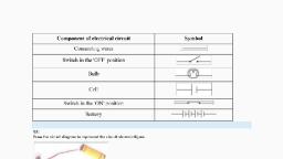
14, , Electric Current, and its Effects, , Y, , ou might have tried the game, ‘How steady is your hand?’, suggested in Chapter 12 of, Class VI. If not, you may try it out now., Paheli and Boojho had also set up the, game by connecting an electric circuit, as suggested in Class VI. They had lots, of fun trying it out with their families, and friends. They enjoyed it so much, that they decided to suggest it to a, cousin of theirs who stayed in a, different town. So, Paheli made a neat, drawing showing how the various, electric components were to be, connected (Fig.14.1)., , Fig. 14.1 Setup to check how steady, your hand is, , Can you draw this circuit, conveniently? It made Boojho wonder if, there was an easier way to represent, these electric components., , 14.1 SYMBOLS OF ELECTRIC, COMPONENTS, Some common electric components can, be represented by symbols. In Table 14.1,, some electric components and their, symbols are shown. You may come, across different symbols for these, components in different books. However,, in this book, we shall be using the, symbols shown here., Look at the symbols carefully. In the, symbol for the electric cell, notice that, there is a longer line and a shorter but, thicker parallel line. Do you recall that, an electric cell has a positive terminal, and a negative terminal? In the symbol, of the electric cell, the longer line, represents the positive terminal and the, thicker, shorter line represents the, negative terminal., For a switch the ‘ON’ position and, the ‘OFF’ position are represented by the, symbols as shown. The wires used to, connect the various components in a, circuit are represented by lines., In Table 14.1, a battery and its, symbol are also shown. Do you know, what a battery is? Look at the symbol of, a battery. Can you make out what a, battery could be? For some of the, activities we may need more than one, cell. So, we connect two or more cells, together as shown in Fig.14.2. Notice, , 160, , SCIENCE, , 2020-21
Page 2 :
Table 14.1 Symbols for some, electric circuit components, S.No. Electric component, 1., , Electric cell, , 2., , Electric bulb, , 3., , Switch in ‘ON’ position, , 4., , Switch in ‘OFF’ position, , Symbol, , Many devices such as torches,, transistors, toys, TV remote controls, use, batteries. However, in some of these, devices the electric cells are not always, placed one after the other as shown in, Fig. 14.2. Sometimes the cells are placed, side by side. Then how are the terminals, of the cells connected? Look carefully, inside the battery compartment of any, device. There is usually a thick wire or, a metal strip connecting the positive, terminal of one cell to the negative, terminal of the next cell (Fig.14.3). In, order to help you to place the cells, correctly in the battery compartment,, ‘+’ and ‘–’ symbols are usually printed, there., How can we connect the cells to, prepare batteries for our activities? You, may make a cell holder, as shown in, Fig.14.4, using a wooden block, two iron, strips and rubber bands. It is necessary, (a), , 5., , (b), , Battery, , Fig. 14.2 (a) A battery of two cells, (b) A battery of four cells, , 6., , Wire, , that the positive terminal of one cell is, connected to the negative terminal of the, next cell. Such a combination of two or, more cells is called a battery., , Fig. 14.3 Connecting two cells together to make, a battery, , ELECTRIC CURRENT AND ITS EFFECTS, , 161, , 2020-21
Page 3 :
terminal of one cell is connected to the, negative terminal of the next cell., Connect a piece of wire each to the two, metal clips on the cell holder as shown, in Fig.14.5. Your battery is ready for, use., The symbol used for representing a, battery is shown in Table.14.1., Let us now draw a circuit diagram of, an electric circuit using symbols shown, in Table 14.1., , Fig. 14.4 A cell holder, , Activity 14.1, , Fig. 14.5 Another type of cell holder, , that the rubber bands hold the metal, strips tightly., You could also buy cell holders from, the market for making batteries of two, or more electric cells. Place the cells in, them properly, such that the positive, Paheli and Boojho wonder whether, the batteries used in tractors, trucks, and inverters are also made from cells., Then why is it called a battery? Can, you help them to find the answer to, this question?, , Fig. 14.6 Truck battery and its cutout, , Make the electric circuit shown in, Fig. 14.7. You used a similar circuit in, Class VI to make an electric bulb glow., Do you remember that the bulb glows, only when the switch is in the ‘ON’, position? The bulb glows as soon as, the switch is moved to the ‘ON’, position., Copy this electric circuit in your, notebook. Make also a circuit diagram, of this circuit using symbols for the, various electric components., Is your diagram similar to the one, shown in Fig. 14.8?, It is much easier to draw a circuit, diagram using symbols. Therefore, we, generally represent an electric circuit by, its circuit diagram., Fig. 14.9 shows another circuit, diagram. Is it identical to the circuit, diagram shown in Fig.14.8? In which, way is it different?, Would the bulb glow in this electric, circuit? Recall that the bulb glows only, when the switch is in the ‘ON’ position, and the electric circuit is closed., , 162, , SCIENCE, , 2020-21
Page 4 :
Fig. 14.9 Another circuit diagram, , electric current passes through it. When, the bulb gets fused, its filament is, broken., , Fig. 14.7 An electric circuit, , CAUTION, Never touch a lighted electric bulb, connected to the mains. It may be very, hot and your hand may get burnt, badly. Do not experiment with the, electric supply from the mains or a, generator or an inverter. You may get, an electric shock, which may be, dangerous. Use only electric cells for, all the activities suggested here., , Fig. 14.8 Circuit diagram of electric circuit, shown in Fig. 14.7, , §, §, , §, , Notice that the key or switch can, be placed anywhere in the circuit., When the switch is in the ‘ON’, position, the circuit from the, positive terminal of the battery to, the negative terminal is complete., The circuit is then said to be closed, and the current flows throughout, the circuit instantly., When the switch is in the ‘OFF’, position, the circuit is incomplete., It is said to be open. No current, flows through any part of the, circuit., , If the filament of the bulb is broken,, would the circuit be complete? Would, the bulb still glow?, You might have noticed that a, glowing electric bulb become warm. Do, you know why?, , 14.2 HEATING EFFECT, CURRENT, , OF, , ELECTRIC, , Activity 14.2, , In the bulb there is a thin wire, called, the filament, which glows when an, , Take an electric cell, a bulb, a switch, and connecting wires. Make an electric, circuit as shown in Fig.14.9. This, activity has to be done using only one, cell. Keep the switch in the ‘OFF’, , ELECTRIC CURRENT AND ITS EFFECTS, , 163, , 2020-21
Page 5 :
position. Does the bulb glow? Touch, the bulb. Now move the electric switch, to the ‘ON’ position and let the bulb glow, for a minute or so. Again touch the bulb., Do you feel any difference? After moving, the switch back to the ‘OFF’ position,, touch the bulb again., , The wire gets hot when an electric, current passes through it. This is the, heating effect of the electric current., Can you think of any electric appliance, where the heating effect of the electric, current is used? Make a list of such, appliances., , Activity 14.3, Make a circuit as shown in Fig.14.10., Take about 10 cm long piece of nichrome, wire and tie it between the nails. (You, can get nichrome wire from an electric, repair shop or you can use a piece of, discarded coil of an electric heater.), Touch the wire. Now switch on the, current in the circuit by moving the, switch to the ‘ON’ position. After a few, , You might have seen an electric, room heater or an electric heater used, for cooking. All these contain a coil of, wire. This coil of wire is called an, element. You may have noticed that, when these appliances are switched on, Boojho could not see element in an, electric iron. Paheli told him that, electrical appliances, such as, immersion heaters, hotplates, irons,, geysers, electric kettles, hair dryers,, have elements inside them. Have you, ever seen the element in any, appliance?, , Fig. 14.10, , CAUTION, Do not keep the switch in the ‘ON’, position for a long time, otherwise the, cell may become weak very quickly., seconds touch the wire. (Do not hold it, for a long time.) Switch off the current., Touch the wire again after a few, minutes., 164, , Fig. 14.11 Element of electric iron, , SCIENCE, , 2020-21
Page 6 :
Fig. 14.12 Glowing filament of an electric bulb, (incandescent), , after connecting to the electric supply,, their elements become red hot and give, out heat., The amount of heat produced in a, wire depends on its material, length, and thickness. Thus, for different, requirements, the wires of different, materials and different lengths and, thicknesses are used., The wires used for making electric, circuits do not normally become hot. On, the other hand, the elements of some, electric appliances become so hot that, they are easily visible. The filament of, , Incandescent electric bulbs (Fig. 14.12) are often used for lighting but they also, give heat. It means that a part of electricity consumed is used in producing, heat. This is not desirable as it results in the wastage of electricity. The fluorescent, tube-lights and compact fluorescent lamps (CFLs) are better electricity efficient, lighting sources. Nowadays, the use of light emitting diode (LED) bulbs is, increasing. For producing a given intensity of light, LED bulbs consume less, electricity as compared to incandescent bulbs or fluorescent tubes or CFLs.Thus, LED bulbs are much electricity efficient and therefore being preferred., , Fig. 14.13 Electric bulb, tube-light, CFL and LED, , It is advised to use electrical appliances and gadgets, which are electricity efficient., Bureau of Indian Standards, New Delhi assigns a Standard Mark on products,, called ISI mark, which is an assurance of conformity to the specifications, given on the products. It is therefore suggested to use ISI mark products., Note: Fluorescent tubes and CFLs contain mercury vapour, toxic in nature., Therefore, damaged fluorescent tubes or CFLs need to be disposed off safely., ELECTRIC CURRENT AND ITS EFFECTS, , 165, , 2020-21
Page 7 :
Fig. 14.15 Fuses used in electrical appliances, , Fig. 14.14 Fuse used in buildings, , an electric bulb gets heated to such a, high temperature that it starts glowing., If a large current passes through a, wire, the wire may become so hot that it, may even melt and break. But is it, possible for a wire to melt and break?, Let us check it out., , buildings fuses are inserted in all, electrical circuits. There is a maximum, limit on the current which can safely, flow through a circuit. If by accident the, current exceeds this safe limit, the wires, CAUTION, Never try to investigate an electric fuse, connected to mains circuit on your, own. You may, however, visit an, electric repair shop and compare the, burnt out fuses with the new ones., , Activity 14.4, Make the circuit we used for Activity 14.3, again. However, replace the cell with a, battery of four cells. Also, in place of, the nichrome wire, tie a thin strand of, steel wool. (The steel wool is commonly, used for cleaning utensils and is, available in grocery shops.) If there are, any fans in the room, switch them off., Now pass the current through the circuit, for sometime. Observe the strand of steel, wool carefully. Note what happens. Does, the strand of steel wool melt and break?, Wires made from some special, materials melt quickly and break when, large electric currents are passed, through them. These wires are used for, making electric fuses (Fig.14.14). In all, , One reason for excessive currents in, electrical circuits is the direct, touching of wires. This may happen if, the insulation on the wires has come, off due to wear and tear. This may, cause a short circuit. Another reason, for excessive current can be the, connection of many devices to a single, socket. This may cause overload in, the circuit. You might have read, reports in newspapers about fires, caused by short circuits and, overloads., may become overheated and may cause, fire. If a proper fuse is there in the circuit,, it will blow off and break the circuit. A, fuse is thus a safety device which, , 166, , SCIENCE, , 2020-21
Page 8 :
These days Miniature, circuit breakers (MCBs), are increasingly being, used in place of fuses., These are switches which, automatically turn off, when current in a circuit, exceeds the safe limit. You, turn them on and the, circuit is once again, complete. Look for ISI, mark on MCBs also., , Fig. 14.16 Miniature, circuit breaker (MCB), , CAUTION, Always, use proper fuses which have, been specified for particular, applications, carrying ISI mark. Never, use just any wire or strip of metal in, place of a fuse., prevents damages to electrical circuits, and possible fires., Fuses of different kinds are used, for different purposes. Fig. 14.14 shows, fuses used in our houses. Fuses, shown in Fig. 14.15 are generally used, in electrical appliances., We observed the heating effect of the, electric current and learnt how we use, it to our advantage. Does the electric, current have other effects also?, , Fig. 14.17 Effect of current on a, compass needle, , wire a few times around the cardboard, tray. Place a small compass needle, inside it. Now connect the free ends of, this wire to an electric cell through a, switch as shown in Fig.14.17., Note the direction in which the, compass needle is pointing. Bring a bar, magnet near the compass needle., Observe what happens. Now, while, watching the compass needle carefully,, move the switch to the ‘ON’ position., , 14.3 MAGNETIC EFFECT OF, ELECTRIC CURRENT, Activity 14.5, Take the cardboard tray from inside a, discarded matchbox. Wrap an electric, ELECTRIC CURRENT AND ITS EFFECTS, , Fig. 14.18 Hans Christian Oersted, (A.D. 1777-1851), 167, , 2020-21
Page 9 :
What do you observe? Does the compass, needle deflect? Move the switch back to, the ‘OFF’ position. Does the compass, needle come back to its initial position?, Repeat the experiment a few times., What does this experiment indicate?, We know that the needle of a compass, is a tiny magnet, which points in, north-south direction. When we bring, a magnet close to it, the needle gets, deflected. We have also seen that, compass needle gets deflected when the, current flows in a nearby wire. Can you, connect the two observations? When the, current flows through a wire, does the, wire behave like a magnet?, This is what a scientist called Hans, Christian Oersted (Fig. 14.18) also, wondered. He was the first person who, noticed the deflection of compass needle, every time the current was passed, through the wire., So, when electric current passes, through a wire, it behaves like a magnet., This is the magnetic effect of the electric, current. In fact, an electric current can, be used to make magnets. Do you find, it too surprising? Let us try it out., , Fig. 14.19 An electromagnet, , Remember not to switch on the, current for more than a few seconds, at a time. The electromagnet weakens, the cell quickly if left connected., , 14.4 ELECTROMAGNET, Activity 14.6, Take around 75 cm long piece of, insulated (plastic or cloth covered or, enamelled) flexible wire and an iron nail,, say about 6–10 cm long. Wind the wire, tightly around the nail in the form of a, coil. Connect the free ends of the wire, to the terminals of a cell through a switch, as shown in Fig 14.19., Place some pins on or near the end, of the nail. Now switch on the current., What happens? Do the pins cling to the, tip of the nail? Switch off the current., Are the pins still clinging to the end of, the nail?, The coil in the above activity behaves, like a magnet when electric current flows, through it. When the electric current is, switched off, the coil generally loses its, magnetism. Such coils are called, electromagnets. The electromagnets, can be made very strong and can lift, very heavy loads. Do you remember the, crane about which you read in Chapter 13, of Class VI? The end of such a crane, has a strong electromagnet attached to, it. The electromagnets are also used to, separate magnetic material from the, junk. Doctors use tiny electromagnets, to take out small pieces of magnetic, material that have accidentally fallen in, , 168, , SCIENCE, , 2020-21
Page 10 :
the eye. Many toys also, electromagnets inside them., , have, , 14.5 ELECTRIC BELL, We are quite familiar with an electric bell., It has an electromagnet in it. Let us see, how it works., Fig. 14.20 shows the circuit of an, electric bell. It consists of a coil of wire, wound on an iron piece. The coil acts, as an electromagnet. An iron strip with, a hammer at one end is kept close to, , Fig. 14. 20 Circuit of an electric bell, , the electromagnet. There is a contact, screw near the iron strip. When the iron, strip is in contact with the screw, the, current flows through the coil which, becomes an electromagnet. It, then,, pulls the iron strip. In the process, the, hammer at the end of the strip strikes, the gong of the bell to produce a sound., However, when the electromagnet pulls, the iron strip, it also breaks the circuit., The current through the coil stops, flowing. Will the coil remain an, electromagnet?, The coil is no longer an electromagnet., It no longer attracts the iron strip. The, iron strip comes back to its original, position and touches the contact screw, again. This completes the circuit. The, current flows in the coil and the, hammer strikes the gong again. This, process is repeated in quick succession., The hammer strikes the gong every time, the circuit is completed. This is how, the bell rings., , Keywords, Battery, Circuit diagram, Electric components, , Electric bell, Electromagnet, Fuse, , Heating effect of current, Magnetic effect of current, , What you have learnt, n, , It is convenient to represent electric components by symbols. Using these,, an electric circuit can be represented by a circuit diagram., , n, , When an electric current flows through a wire, the wire gets heated. It is, the heating effect of current. This effect has many applications., , ELECTRIC CURRENT AND ITS EFFECTS, , 169, , 2020-21
Page 11 :
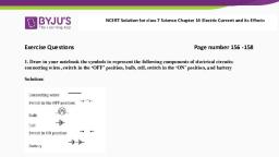
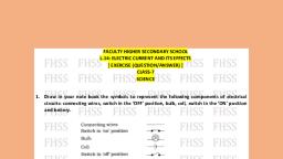
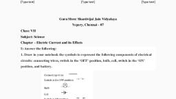
n, , Wires made from some special materials melt quickly and break, when large electric currents are passed through them. These, materials are used for making electric fuses which prevent fires, and damage to electric appliances., , n, , When an electric current flows through a wire, it behaves like a, magnet., , n, , A current carrying coil of an insulated wire wrapped around a, piece of iron is called an electromagnet., , n, , Electromagnets are used in many devices., , Exercises, 1. Draw in your notebook the symbols to represent the following, components of electrical circuits: connecting wires, switch in the ‘OFF’, position, bulb, cell, switch in the ‘ON’ position, and battery, 2. Draw the circuit diagram to represent the circuit shown in Fig.14.21., , Fig. 14.21, 3. Fig.14.22 shows four cells fixed on a board. Draw lines to indicate how, you will connect their terminals with wires to make a battery of four, cells., , Fig. 14.22, 4. The bulb in the circuit shown in Fig.14.23 does not glow. Can you, identify the problem? Make necessary changes in the circuit to make, the bulb glow., , 170, , SCIENCE, , 2020-21
Page 12 :
Fig. 14.23, 5. Name any two effects of electric current., 6. When the current is switched on through a wire, a compass needle kept, nearby gets deflected from its north-south position. Explain., 7. Will the compass needle show deflection when the switch in the circuit, shown by Fig.14.24 is closed?, , Fig. 14.24, 8. Fill in the blanks:, (a), , Longer line in the symbol for a cell represents its, , terminal., , (b), , The combination of two or more cells is called a, , (c), , When current is switched ‘on’ in a room heater, it, , (d), , The safety device based on the heating effect of electric current is, called a, ., , ., ., , 9. Mark ‘T’ if the statement is true and ‘F’ if it is false:, (a), , To make a battery of two cells, the negative terminal of one cell is, connected to the negative terminal of the other cell. (T/F), , (b), , When the electric current through the fuse exceeds a certain limit,, the fuse wire melts and breaks. (T/F), , (c), , An electromagnet does not attract a piece of iron. (T/F), , (d), , An electric bell has an electromagnet. (T/F), , 10. Do you think an electromagnet can be used for separating plastic bags, from a garbage heap? Explain., , ELECTRIC CURRENT AND ITS EFFECTS, , 171, , 2020-21
Page 13 :
11. An electrician is carrying out some repairs in your house. He wants to, replace a fuse by a piece of wire. Would you agree? Give reasons for, your response., 12. Zubeda made an electric circuit using a cell holder shown in Fig. 14.4,, a switch and a bulb. When she put the switch in the ‘ON’ position, the, bulb did not glow. Help Zubeda in identifying the possible defects in the, circuit., 13. In the circuit shown in Fig. 14.25, , B, , A, , C, , Fig. 14.25, (i), (ii), , Would any of the bulb glow when the switch is in the ‘OFF’, position?, What will be the order in which the bulbs A, B and C will glow, when the switch is moved to the ‘ON’ position?, , Extended Learning — Activities and Projects, 1. Set up the circuit shown in Fig. 14.17 again. Move the key to ‘ON’, position and watch carefully in which direction the compass needle, gets deflected. Switch ‘OFF’ the current. Now keeping rest of the circuit, intact, reverse the connections at the terminal of the cell. Again switch, ‘on’ the current. Note the direction in which the needle gets deflected., Think of an explanation., , Paheli and Boojho saw a magic trick sometime back. The magician placed, an iron box on a stand. He then called Boojho and asked him to lift the, box. Boojho could easily lift the box. Now the magician made a show of, moving his stick around the box while muttering some thing. He again, asked Boojho to lift the box. This time Boojho could not even move it. The, magician again muttered some thing and now Boojho could lift the box., The audience, including Paheli and Boojho, were very impressed with, the show and felt that the magician had some supernatural powers., However, after reading this chapter Paheli is wondering if the trick was, indeed some magic or some science was involved? Can you guess what, science might be involved?, , 172, , SCIENCE, , 2020-21
Page 14 :
2. Make four electromagnets with 20, 40, 60 and 80 turns. Connect them, one by one to a battery of 2 cells. Bring the electromagnet near a box of, pins. Count the number of pins attracted by it. Compare the strengths, of the electromagnets., 3. Using an electromagnet, you can make a working model of a railway, signal as shown in Fig.14.26., , Cardboard signal, Thread, , Iron nail, , Coil, , Fig. 14.26 A working model of a railway signal, 4. Visit an electric shop. Request an electrician to show you the various, types of fuses and MCB and to explain how they work., , Did You Know?, The credit for the invention of the electric bulb, is usually given to Thomas Alva Edison, though, others before him had worked on it. Edison, was a remarkable man. He made some 1300, inventions including the electric bulb,, gramophone, the motion picture camera and, the carbon transmitter, which facilitated the, invention of the telephone., , Fig. 14.27 Thomas Alva Edison, (A.D. 1847 – 1931), , ELECTRIC CURRENT AND ITS EFFECTS, , 173, , 2020-21