Notes of MHT - CET, Physics Wave Optics NOTES - Study Material
Page 1 :
CHAPTER 1. WAVE OPTICS, (Interference and Diffraction)
Page 3 :
What is Light?, Light is an electromagnetic radiation refers to visible, regions of electromagnetic spectrum corresponding to, the wavelength range of 400nm to 760nm which has, transverse vibrations., , Wave
Page 4 :
General Definitions, The Wavelength of a sin wave,, λ, can be measured between, any two points with the same, phase, such as between crests,, or troughs, as shown., The frequency, f, of a wave is, the number of waves passing a, point in a certain time. We, normally use a time of one, second, so this gives frequency, the unit hertz (Hz), since one, hertz is equal to one wave per, second.
Page 6 :
Principle of Superposition, “Whenever two or more waves superimpose in a medium, the, total displacement at any point is equal to the vector sum of, individual displacement of waves at that point”, If Y 1, Y 2, Y 3…are different, displacement vector due to, the waves 1,2,3 …acting, separately then according to, the principle of superposition, the resultant displacement is, given by, Y=Y1+Y2+Y3+……
Page 7 :
INTERFERENCE, , is the process in which two or more, waves of the same frequency - be it light, sound, or other electromagnetic, waves - either reinforce or cancel each other, the amplitude of the resulting, wave being equal to the sum of the amplitudes of the combining waves., For example, if at a given instant in time and location along the medium, the, crest of one wave meets the crest of a second wave, they will interfere in such, a manner as to produce a "super-crest." Similarly, the interference of a trough, and a trough interfere constructively to produce a "super-trough." This is, called constructive interference. If the two amplitudes have opposite signs,, they will subtract to form a combined wave with a lower amplitude. For, example, the interaction of a crest with a trough is an example of destructive, interference. Destructive interference has the tendency to decrease the, resulting amount of displacement of the medium. The bright bands show, constructive interference of light. The dark bands show destructive, interference of light.
Page 9 :
MICHELSON’S INTERFERROMETER, The Michelson interferometer is a, configuration for optical interferometer, invented by Albert Abraham Michelson, Using a beam splitter, a light source is, two arms., , common, and was, in 1887., split into
Page 10 :
Principle:- The MI works on the principle of division of amplitude., When the incident beam of light falls on a beam splitter which divided, light wave in two part in different directions. These two light beams, after traveling different optical paths, are superimposed to each other, and due to superposition interferences fringes formed.
Page 11 :
Construction:- It consists of two highly polished plane mirror M1 and M2, with, two optically plane glass plate G1 and G2 which are of same material and same, thickness. The mirror M1 and M2 are adjusted in such a way that they are, mutually perpendicular to each other. The plate G1 and G2 are exactly parallel to, each other and placed at 45° to mirror M1 and M2. Plate G1 is half silvered from, its back while G2 is plane and act as compensating plate. Plate G1 is known as, beam-splitter plate., The mirror M2 with screw on its back can slightly titled about vertical and, horizontal direction to make it exactly perpendicular to mirror M1. The mirror, M1 can be moved forward or backward with the help of micrometer screw and, this movement can be measured very accurately., Working: Light from a broad source is made paralied by using a convex lens L., Light from lens L is made to fall on glass plate G1 which is half silver polished, from its back. This plate divides the incident beam into two light rays by the, partial reflection and partial transmission, known as Beam splitter plate. The, reflected ray travels towards mirror M1 and transmitted ray towards mirror M2., These rays after reflection from their respective mirrors meet again at 'O' and, superpose to each other to produce interference fringes. This firings pattern is, observed by using telescope.
Page 12 :
Functioning of Compensating Plate: In absence of plate G2 the reflected ray passes, the plate G1 twice, whereas the transmitted ray does not passes even once., Therefore, the optical paths of the two rays are not equal. To equalize this path the, plate G2 which is exactly same as the plate G1 is introduced in path of the ray, proceeding towards mirror M2 that is why this plate is called compensating plate, because it compensate the additional path difference., , Formation of fringes in MI
Page 15 :
The shape of fringes in MI depends on inclination of mirror M1 and M2. Circular fringes are, produced with monochromatic light, if the mirror M1 and M2 are perfectly perpendicular to, each other. The virtual image of mirror M2 and the mirror M1 must be parallel. Therefore it is, assumed that an imaginary air film is formed in between mirror M1 and virtual image mirror, M'2. Therefore, the interference pattern will be obtained due to imaginary air film enclosed, between M 1 andM'2., From Fig. if the distance M1 and M2 and M'2 is'd',, the distance between S'1 and S'2 will be 2D., If the light ray coming from two virtual sources, making an angle θ with the normal then the path, difference between the two beams from S1 and S2, will becomes, , As one of the ray is reflecting from denser medium, mirror M1, a path change of λ/2 occurs in it. Hence, the effective path difference between them will be
Page 16 :
If this path difference is equal to an integral number of wavelength λ, the condition for, constructive interference is satisfied. Thus the bright fringe will formed., , If this path difference is equal to an integral number of wavelength (2n±1)λ/2, the condition, for destructive interference is satisfied. Thus the dark fringe will formed.
Page 17 :
Radius of Fringes, The Condition for maxima and minima in MI is given by, For maxima, , For minima, , It is clear that on moving away from center the value of angle θ increases and the value, of cos θ decreases hence the order of fringe also decrease so n maximum at center, The, condition for nth dark ring at center is, On moving m number of rings away from the center, the, order of mth ring will be ( n-m). If mth ring make an angle, θm with the axis of telescope then from equation, , rm, , ……………Eq 2, On Subtracting eq 1 and 2, …Eq 3, Here, …Eq 4, , n-1, , n, , ……………Eq 1, , D, , θm, , n-2, nm, m
Page 19 :
Applications of MI, (1) Measurement of the wavelength of monochromatic light : The mirror M1 and, M2 adjusted such that circular fringes are formed. For this purpose mirror M1 and, M2 are made exactly perpendicular to each other., Now set the telescope at the center of fringe and move the mirror M1 in any, direction, number of fringes shifted in field of view of telescope is counted., Let on moving mirror M1 through x distance number of fringes shifted is N So the, path difference, , By using both equations we will calculate wavelength corresponding to distance, and number of fringes shifted through telescope., (2) Determination of the difference in between two nearby wavelengths :- Suppose, a source has two nearby wavelengths λ1 and λ2. Each wavelength gives rise its, own fringe pattern in MI. By adjusting the position of the mirror M1, aposition, will be found where fringes from both wavelength will coincide and form highly, contrast fringes.
Page 20 :
So the condition is given by, ……………Eq 1, When a mirror M1 has been moved through a certain distance, the bright fringe due to, wavelength λ1 coincide with dark fringe due to wavelength λ2 and no fringe will be, seen. On further movies mirror M1 the bright fringes again distinct, this is the position, where n1+m order coincide with n2+m+1., So the condition given by, ……………Eq 2, Subtracting eq 2 by eq 1, ……………Eq 3, ……………Eq 4, So by eq 4 and 3
Page 21 :
Problems & Solution, Q.1. In MI 200 fringes cross the field of view when the movable mirror is displaced through, 0.05896mm. Calculate the wavelength of the monochromatic light used., Solution:- Given, N=200, x= 0.05896mm = 0.05896 X 10⁻³ m, So the wavelength, , Å, , Q.2. The initial and final readings of MI screw are 10.7347 mm and 10.7057mm, respectively, when 100 fringes pass trough the field of view. Calculate the wavelength of, light used., Solution:- Given, N=100, x=x2-x1= 10.7347-107057=0.029mm=0.029 X 10 -3m, So the wavelength, , Å
Page 22 :
Problems & Solution, Q.3. MI is set to form circular fringes with light of wavelength 5000Å. By Changing the, path length of movable mirror slowly, 50 fringes cross the center of view How much path, length has been changed?, Solution:- Given, N=50, λ= 5000 X 10 -10m, So the path length, Q.4. In a Michelson Interferometer, when 200 fringes are shifted, the final reading of the, screw was found to be 5.3675mm. If the wavelength of light was 5.92 X 10⁻⁷ m, What was, the critical reading of the screw?, Solution:- Given, N=200, x=x2-x1= 5.3675 X10⁻³m - ?, and wavelength λ = 5.92 X 10⁻²m, So the wavelength, , Now initial reading of screw d 1=d2 ± x = 5.3675 x 10 -3m + 0.0592 x10 -3m =5.4267 x 10 -3m
Page 23 :
NEWTONS RING, Newton's rings is a phenomenon, in which an interference pattern is, created by the reflection of light, between two surfaces—a spherical, surface and an adjacent touching, flat surface. It is named for Isaac, Newton, who first studied the effect, in 1717. When viewed with, monochromatic light, Newton's, rings appear as a series of, concentric, alternating bright and, dark rings centered at the point of, contact between the two surfaces., , Newton's rings seen in two plano-convex lenses with their flat surfaces in contact. One surface is, slightly convex, creating the rings. In white light, the rings are rainbow-colored, because the, different wavelengths of each color interfere at different locations.
Page 24 :
1. Construction
Page 25 :
2. Theory
Page 26 :
Theory Explanation, When a Plano convex lens of long focal length is placed in contact on a plane glass, plate (Figure given below), a thin air film is enclosed between the upper surface of, the glass plate and the lower surface of the lens. The thickness of the air film is, almost zero at the point of contact O and gradually increases as one proceeds, towards the periphery of the lens. Thus points where the thickness of air film is, constant, will lie on a circle with O as center., By means of a sheet of glass G, a parallel beam of monochromatic light is, reflected towards the lens L. Consider a ray of monochromatic light that strikes the, upper surface of the air film nearly along normal. The ray is partly reflected and, partly refracted as shown in the figure. The ray refracted in the air film is also, reflected partly at the lower surface of the film. The two reflected rays, i.e., produced at the upper and lower surface of the film, are coherent and interfere, constructively or destructively. When the light reflected upwards is observed, through microscope M which is focused on the glass plate, series of dark and, bright rings are seen with center as O. These concentric rings are known as ", Newton's Rings "., At the point of contact of the lens and the glass plate, the thickness of the film, is effectively zero but due to reflection at the lower surface of air film from denser, medium, an additional path of λ/2 is introduced. Consequently, the center of, Newton rings is dark due to destructive interference.
Page 29 :
Diffraction of Light, Diffraction refers to various phenomena that occur when a, wave encounters an obstacle or a slit. It is defined as the, bending of light around the corners of an obstacle or, aperture into the region of geometrical shadow of the, obstacle., , Thomas, Young's, sketch, of, two-slit, diffraction, which he presented to the Royal, Society in 1803., , Diffraction, pattern, of red laser beam, made on a plate, after, passing, through, a, small, circular aperture in, another plate
Page 30 :
Classification of Diffraction, Diffraction phenomena of light can be divided into two, different classes, Fresnel's Diffraction, Fraunhofer diffraction, , Cylindrical wave fronts, , Planar wave fronts, , Source of screen at finite distance from, the obstacle, , Observation distance is infinite. In, practice, often at focal point of lens., , Move in a way that directly, Fixed in position, corresponds with any shift in the object., Fresnel diffraction patterns on flat, surfaces, , Fraunhofer diffraction patterns on, spherical surfaces., , Change as we propagate them further, Shape and intensity of a Fraunhofer, ‘downstream’ of the source of scattering diffraction pattern stay constant.
Page 31 :
Fraunhofer Diffraction at a Single Slit, Let us consider a slit be rectangular, aperture whose length is large as, compared to its breath. Let a parallel, beam of wavelength be incident, normally upon a narrow slit of AB., And each point of AB send out, secondary wavelets is all direction., The rays proceeding in the same, direction as the incident rays are, focused at point O and which are, diffracted at angle θ are focused at, point B. The width of slit AB is small a., The path difference between AP and, BP, is, calculated, by, draw, a, the phase, perpendicular BK., difference, According to figure the path difference, …………….., eq 1, , …………….., eq 2
Page 32 :
According to Huygens wave theory each point of slit AB spread out secondary, wavelets which interfere and gives diffraction phenomena. Let n be the, secondary wavelets of the wave front incident on slit AB . The resultant, amplitude due to all equal parts of slit AB at the point P can be determine by the, method of vector addition of amplitude. This method is known as, , polygon method, For this construct a polygon of vector that magnitude Ao represent the, amplitude of each wavelets and direction of vector represented the phase of, each wavelets, A, , A, n, δ, , r, C, , R, δ, B, , 2, δ, , R/, 2, N, , δ/, 2, δ/, 2, , R/, 2, , nɸ=, δ, B, , nɸ=, δ
Page 33 :
By assuming polygon as a arc of a circle of radius r we can, calculate the angle, , Now a perpendicular CN is draw from the center C of an arc on the line A,, which will divide the amplitude R in two parts, from triangle ACN and BCN, By assuming δ/2 =α=π/λ a, sinθ, , and the intensity I is, given by, AC=BC = r, so, By putting the values, of r
Page 34 :
Intensity distribution by single slit diffraction, , Central Maxima, For the central point P on the screen θ = 0 and hence α =, 0, Hence intensity at point P will be, , Hence intensity at point P will be, maximum, Principal, , Minima, , For the principal minima intensity should be zero, , Where n = 1, 2, 3,4……, n=0
Page 35 :
Secondary, Maxima, , To find out direction of secondary, maxima we differentiate intensity, equation with respect to α and, equivalent to zero, , The point of intersection of two, curves, gives, the, position, of, secondary maxima. The positions are, α1 = 0, α2 = 1.43π, α3 = 2.46π, α4 = 3.47π,, .., , This is the condition for secondary, maximas and can be solved by, plotting a graph between y= tanα, and y=α as shown
Page 36 :
Intensity distribution by single slit diffraction, , Principal, Minima’s, , Central, maxima, Secondary, maxima’s
Page 37 :
Width of the central maximum, The width of he central maximum can, be derived as the separation between, the first minimum on either side of, the central maximum., , θ1, , x, , If he first maximum is at distance x, from the central maximum then, …………….., eq 1, We know, that, …..eq, 2, , …..eq, 3, , From the, diagram, , x, , f, D, …..eq, 4, , If θ is very small sinθ1 =, tanθ1 = θ1
Page 38 :
Diffraction Grating, A diffraction grating is an arrangement equivalent to a large number of, parallel slits of, equal widths and separated from one another by equal opaque spaces., , Constructi, on, , Diffraction grating can be made, by drawing a large number of, equidistant and parallel lines on, an optically plane glass plate, with the help of a sharp, diamond point. The rulings, scatter the light and are, effectively opaque, while the, unruled parts transmit light and, act as slits. The experimental, arrangement, of, diffraction, grating is shown, They are two type refection and
Page 39 :
A very large reflecting, diffraction grating, , An, incandescent, light bulb viewed, through, a, transmissive, diffraction grating.
Page 40 :
Theory for transmission grating, (resultant intensity and amplitude), Let AB be e section of a grating having wid of, each slit as a, and b e wid of each opaque space, betw n e slits. The quantity (a + b) is ca ed, grating element, and two consecutive slits separated, by e distance (a + b) are ca ed c responding points., The schematic ray diagram of grating has b n shown, in figure, , Let a para el beam of light of waveleng λ incident n ma y on e grating using e e y of, single slit & Huygens principle, e amplitude of e wave diffracted at angle θ by each slit is given by, , ……………………eq 1
Page 41 :
Diffraction by n para el slit at an angle θ is equivalent to N para el waves of amplitude R, , ……………………eq 2, , That emitted from each slit s1, s2 , s3 …..sN Where α = π/λ (a sinθ), These N para el waves interfere and gives, diffraction pattern consisting of maxima and minima on e scr n., The pa difference betw n e waves emitted from two consecutive slits given by., , ……………………eq 3, The c responding Phase Difference, ……………………eq 4, Thus, , ere are N equal waves of equal amplitude and wi, , a increasing phase difference of δ
Page 42 :
To find e resultant amplitude of ese N para el waves we use e vect polygon me od. Waves from each slit, is represented by vect s where its magnitude represented by amplitude and direction represents e phase., Thus joining, is δ, , e N vect s tail to tip we get a polygon of N equal sides and e angle betw n two consecutive sides, , The phase difference betw n waves from first to last slit is Nδ obtained by drawing, , A, , A, Nδ, , N, , r, C, , Nδ/2, Nδ/2, , RN, , δ, B, , e tangents at A and B, , 2, δ, , RN, Nδ, , Nδ, B
Page 43 :
Diffraction by n para el slit at an angle θ is equivalent to N para el waves of amplitude RN., Consider a triangle ACN and DCN, C, δ/2 δ/2, , A, , Since AC=CD we can re ite, ……………………eq 5, In triangle ABC, , Here, , ……………………eq 6, , R/2, , N, , R/2, , D
Page 44 :
So, , e resultant intensity, , ……………………eq 7, , The above equation gives e resultant intensity of N para el waves diffracted at an angle θ. The resultant, intensity is e product of two terms, , Due to diffraction from each slit, Due to Interference of N slits, , Intensity distribution by diffraction Grating, , 1. Due to Diffraction from Each Slit, Principal, Central Maxima, Minima, , Hence intensity at point P will be, , Where m = 1, 2, 3,4……
Page 45 :
Secondary, Maxima, 2. Due to Interference of N slits, Principal, Maxima’s, , Position of Principal maxima’s obtained when, Then sinNβ is also equal to zero and, using L’ Hosptal Rule, , Where n= 0, 1, 2, 3……….., becomes indeterminate so by, , Hence the intensity of principal maxima is given by
Page 46 :
Manima’s, The intensity will be minimum when I = 0 i.e. sinNβ = 0 but sinβ ≠ 0, Nβ = ±pπ here p = 1, 2, 3………..(N-1)(N+1)…….(2N-1)(2N+1)…….. i.e. p ≠ N, 2N……, hence, , Secondary, Maxima’s, , To find out direction of secondary maxima we differentiate intensity equation, with respect to α and equivalent to zero, , The solution of the above, equation except p=±nπ gives the, position, of, the, secondary, maxima’s
Page 47 :
Intensity of Secondary Maxima’s, The position of secondary maxima is given by, equation a right triangle can be formed as shown, C, From, figure, , using this, , 1, , 2, , +N, 1, ( 2, / N, A, β, , n, ta, , β), , Ntanβ, , 2, , B, , As increase in number of slit, the number of secondary, maxima also increases
Page 48 :
Intensity distribution by Diffraction Gratings
Page 49 :
Formation of Spectra with Diffraction Grating, With White, Light, , With Monochromatic, Light
Page 50 :
Characteristics of Grating Spectra, 1. ABSENT SPECTRA, If the angle of diffraction is such that, the minima due to diffraction, component in the intensity distribussion falls at the same position of, principal maxima due to interference component, then the order of principal, maxima then absent. If mth order minima fall on nth order principal maxima, then, ……………, eq 1, ……………, eq 2, , ……………, eq 3, Now we consider some cases, A., , If b=a, i.e. width of opaque space in equal to width of slit then from, equation 3. n = 2m since m=1, 2, 3 …. Then n = 2nd, 4th , 6th ….spectra will be, absent, , B. If b=2a, i.e. width of opaque space in equal to width of slit then from, equation 3. n = 3m since m=1, 2, 3 …. Then n = 3rd, 6th , 9th ….spectra will be
Page 51 :
2. Maximum Number of Order Observed by Grating, Principal maximum in grating spectrum is given by, , …………….., eq 1, Maximum possible angle of diffraction is 90 degree therefore, S, o, , …………….., eq 2, , Q.1. A plane transmission grating has 6000 lines/cm. Calculate the higher order of, spectrum which can be seen with white light of wavelength 4000 angstrom, Sol. Given a+b=1/6000, Wavelength 4000X 10-8 cm, As we know that gratings equation written as, For maximum order, Maximum order will be 4th
Page 53 :
4. Dispersive Power of Diffraction Gratings, For a definite order of spectrum, the rate of change of angle of diffraction θ with, respect to the wavelength of light ray is called dispersive power of Grating., Dispersive Power = dθ/dλ, , …………….., eq 1, , We know that gratings equation, , …………….., eq 2, Also written as, , …………….., eq 3
Page 54 :
5. Experimental demonstration of diffraction grating to, determine wavelength
Page 56 :
Resolving Power, Resolution, When two objects or their images are very close to each other they appeared as a one and it not, be possible for the eye to seen them separate. Thus to see two close objects just as separate is, called resolution, , Limit of resolution, The smallest distance between two object,, when images are seen just as separate is, known as limit of resolution, , For eye limit of resolution is 1 minutes, , Resolving Power, The ability of an optical instrument to produce two distinct separate images of two objects, located very close to each other is called the resolution power
Page 57 :
Rayleigh Criterion for Resolution, L d Rayleigh (1842-1919) a British Physicist proposed a criterion which can manifest, when two object are s n just separate is criterion is ca ed Rayleigh’s Criterion f, Resolution, , We Resolved, , Just resolved, , Not resolved
Page 58 :
Resolving power of a telescope, Resolving power of telescope is defined as the reciprocal of the smallest, angle sustained at the object by two distinct closely spaced object points, which can be just seen as separate ones through telescope., Let a is the diameter of objective telescope as shown in fig and P1 and P2, are the positions of the central maximum of two images. According to, Rayleigh criterion these two images are said to be separated if the, position of central maximum of the second images coincides with the, d, first minimum or vice versa., A d, The path difference between, AP2 and BP2 is zero and the, path difference between AP1, and BP 1 is given by, …………….., eq 1, If dθ is very small sin dθ = dθ, ………e, q2, For rectangular, aperture, , θ, , θ, , P, 1, , a, C, d, θ, , P, 2, , B, , For circular, aperture
Page 59 :
Resolving power of a Diffraction Grating, The resolving power of a grating is e ability to separate e spectral lines which are very close to each o er., When two spectral lines in spectrum produced by diffraction grating are just resolved, en in is position, e ratio of e waveleng difference and e mean wave leng of spectral lines are ca ed resolution limit of, diffraction Grating, , Let para el beams of light of waveleng λ and λ+dλ be, incident n ma y on e diffraction grating. If n, principal maxima of λ and λ+dλ are f med in e, direction of θn , θn+dθn respectively, F, e principal maximum by waveleng λ e gratings, equation itten as, , λ+dλ, A, dθ, , f, , waveleng, , dλ, ……………………….....eq 1, , δθn, θn λ, , Q, P
Page 62 :
Thanking
 Learn better on this topic
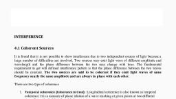