Page 1 :
CHAPTER, , 2, , Vapour Compression System, , 2.1 INTRODUCTION, , i, , u s g viod, , Vapour Compression Refrigeration System, Vapour compression refrigeration system is a modified and corrected form of air, refrigeration system in which working medium is in vapour state. Refrigerant is used as a, working medium in this system., , Main refrigerants are as follows, , NH (Ammonia), , CO (Carbon dioxide), , SO, (Sulphur dioxide), The refrigerant used in this system goes, , through the cyclic process. Condenser is attached, In, this, evaporator., system the refrigerant first enters the evaporator where it absorbs, the latent heat of brine solution. After absorbing the latent heat refrigerant circulates into, the cooling chamber. When it enters the condenser it gives the latent heat to cold water, obtained from cooler and producing refrigeration effect., to the, , 2.2, , ELEMENTS OF VAPOUR COMPRESSION REFRIGERATION, SYSTEM, , Main elements of vapour compression refrigeration system are, , (a) Compressor, , (b) Condenser, , (c) Evaporator, , (d) Receiver, , (e) Expansion device, , (a) Compressor: Main function of compressor is to remove the vapour from evaporator, and increase the pressure and temperature such that refrigerant is condensed into condenser., b) Condenser : It works as a heat exchanger equipment. Main function of condenser is, to absorb the heat from hot refrigerant., , c)Evaporator : It provides the surface for heat transfer through which heat is, transferred., , (d) Receiver:It works as a storage medium in which condensed liquid is filled so that, continuous supply of liquid is done in evaporator., (e) Expansion device : Main funetion of expansion device is to control amount of, refrigerant in the evaporator. It also controls the pressure of inlet liquid so that the liquid, vapourises at low pressure and absorption of heat is more.
Page 2 :
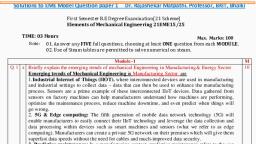
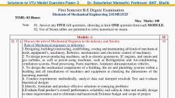
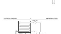
141Refrngeration and Air Conditioning, Insuiated coid chamber, , Low pressure liquid, vapour mixture, , Evaporator, Pressure gauge, , Low pressure vapour, , Expansion valve, , or refrigerant, control valve, , Pressure gauge, , High pressure vapour, , Low pressure side, , High pressure liquid, , High pressure side), Condenser, Compressor, Receiver, , High pressure liquid, vapour mixture, , Fig. 2.1. Simple vapour compression refrigeration system., , 2.3, , PRESSURE-ENTHALPY CHART (P-H CHART), , In pressure-enthalpy chart vertical axis represents pressure and horizontal axis, represents enthalpy. At critical point saturated liquid line and saturated vapour line become, a single line., , In pressure-enthalpy chart:, , Critical point, , Saturated water line is a line, where temperature converted, into saturated temperature and, into, converted, pressure, saturated pressure., Left hand space or region of, saturated liquid line is known, as subcooled liquid region., , The middle region of saturated, , TIT, , Critical pressure, , Superheated, , Sub-cooled, , liquid region, , Wet' vapour, , vapour region, , regien, , Saturated, vapour line, , e, , line is, known as wet steam region., , liquid line and, , steam, , Right hand space of saturated, known, line, is, superheated steam line., steam, , Diagram is as follows, , as, , Enthalpy, Fig. 2.2. Pressure-enthalpy (p-h) chart
Page 3 :
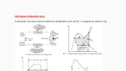
Vapour Compression System I 15, , 2.4, , T-S DIAGRAM (TEMPERATURE-ENTROPY DIAGRAM), 1 to 2 Compression of vapour, Superheated varpour removed in condenser, , 2 to 3, , 3 to 4 Vapour converted into liquid in condenser, 4 to 5 Liquid flashes into liquid chamber + vapouracross expansion valve, 5 to 1 Liquid +vapour converted to all vapour in evaporator, , Superheated, vapour, , Saturated, , Liquid, Isobars, , 5, , Liquid+ Vapour, , YSaturated, 1vapouy, , Specific Entropy (S), Fig. 2.3, , 2.5, , VAPOUR COMPRESSION CYCLE WITH DRY SATURATED, VAPOUR, Pa, , 1 T 3 Cond., TT, , Pa 3Cond., , /, , O, , Evap., , 4 Evap, Entropy, , S, , S2, , h, , (a) T-S diagram, , h2, h4 h, Enthalpy, (b) p-h diagram, , hr, , Fig. 2.4, , The four processes during the eycle are as follows:, 1. Compression process During this process, the low pressure and temperature, vapour refrigerant is compressed isentropically, due to which vapour is converted into dry
Page 4 :
16IRefrigeration and Air Conditioning, and saturated vapour refrigerant. The systematic processes are shown in n, p-h, diagram. Vertical line 1-2 represents the compression process., , and Ts, , During process pressure and temperature increase from Pi to p2 and, nd T7, to, to T,. Wa, , T, , during process is ha -, , T2. Work, donu, , h., , 2. Condensing process : The high pressure and temperature vapour refrigera, , the compressor is passed through the condenser where it is completely condensed at eo, , pressure p, and temperature ?2, as shown by the horizontal line 2-3 on T-S andp-h dias, The vapour refrigerant is changed into liquid refrigerant. The refrigerant, while na, through the condenser, gives its latent heat to the surrounding condensing medium., 3., , p Pa and temperat, is expanded by throttling process through the expansion valve to a low preseture, , Expansion process, , Ts -T, , P P i and temperature T, , line 3-4 in, , :, , The, , liquid refrigerant, , at pressure, , =, , = T as shown by the curve 3-4 in T-s diagram and by the vertir, , p-h diagram. We have already discussed that, , tical, , of the liquid refrigeran, evaporates as it passes through the expansion valve, but the greater portion is vaporised in, , the evaporator. We know that, the liquid refrigerant., , some, , during the throttling process, no heat is absorbed or rejected by, , Note: (a) In case an expansion cylinder is used in place, of throttle or expansioin valve to, the, expand, liquid refrigerant, then the refrigerant will expand isentropically as shown by, dotted vertical line in T-S diagram 2.4. The isentropic, expansion reduces the external work, being expanded in running the compressor and increases the refrigerating effect. Thus, the, net result of using the expansion, cylinder is to increase the coefficient of, , performance., , Since the, , expansion cylinder system of expanding the liquid refrigerant, , is, , quite, , complicated and involves greater initial cost, therefore its use is not justified for small gain in, cooling capacity. Moreover, the flow rate of the refrigerant can be controlled with throttle, valve which is not possible in case of expansion cylinder which has a fixed cylinder volume., , (b) In modern domestic refrigerators,, , a, , expansion valve., , capillary (small, , bore tube), , is, , used, , 4., , in, , place of an, , Vaporising process : The liquid-vapour mixture of the refrigerant at pressure P4 Pi, temperature T T1 is evaporated and changed into vapour refrigerant at constant, =, , and, pressure and temperature, as shown by the horizontal line 4-1 in T-S and p-h diagrams., During evaporation, the liquid-vapour refrigerant absorbs its latent heat of vaporisation from, the medium (air, water or brine) which is to be cooled. This, heat which is absorbed by the, refrigerant is called refrigerating effect and it is briefly written as Rp. The process o, =, , vaporisation continues upto point 1 which is the starting point and thus the cycle 13, , completed., We know that the refrigerating effect or the heat absorbed or extracted by the, , liquid-vapour refrigerant during evaporation, R, , where, , per kg of refrigerant, , is, , given by, , = h1 - hy = h1 - hys, , hrsSensible heat at temperature 73. i.e., enthalpy of liquid, , refrigerant leaving the condenser
Page 5 :
Vapour Compression System I 17, It may be noticed from the cycle that the liquid-vapour refrigerant has extracted heat, during evaporation and the work will be done by the compressor for isentropic compression of, the high pressure and temperature vapour refrigerant., , Coefficient of performance,, , C.O.P Refrigerating effect h -h 1 hfs, Work done, , hg - h, , ha - h, , 2.6 VAPOUR COMPRESSION CYCLE WITH WET VAPOUR, Complete process, , is, , same as, , in, , dry saturated vapour compression refrigeration system., , p-h and T-s diagrams are as follows, , /Cond., , 3/Cond., , TT, , PFPa, , ET-T, , 4 Evap., , 4Evap, , LhrP4 h,=P2, , Entropy, , Entropy(b) p-h diagram, , (a) T-S diagram, Fig. 2.5, In this, , cycle enthalpy is obtained by dryness fraction, calculated by equating at point 1 and point 2., , at, , point, , B., , Dryness fraction, , is, , cOP=etrigerating Effect (R), Work, , cOP-h-hrs, ha -h, VAPOUR, , VAPOUR, There, , are, , COMPRESSION CYCLE WITH, , two situations in, , this cycle:, , (Gi) After compression, , (ii) Before compression, , (1) After compression, The p-h and T-s diagrams are as follows, , SUPERHEATED
Page 6 :
18, , Refrigeration and Air, , T, , Conditioning, , Cond. 1, , T2, , T, , TT, , Exp, Comp., , Exp., , Cond. 2, , Pe-PPa, PPA, , Evap., , Evap., , hh, , Entropy, , Oomp., , Enthalpy, , h2, , (b) ph- diagram, , (a) T-S diagram, , Fig. 2.6, Calculation of enthalpy at point 2 in cycle is done by degree of superheat. Degreee of, of ssuper, equating entropy at points 1 and 2., heat is calculated, , by, , COP, , h, , -, , hs, , ha -, , h1, , Low COP is obtained by superheating because in this process comparatively high, refrigeration effect is obtained. All the process is same as in dry and saturated vapor, compressioin process. The only difference is in process 2-3. In this process superheated vapour, is cooled in two stages (i.e., 2-2 and 2-3). In 2-2 vapour is condensed at constant pressure, and in 2-3 vapour is condensed at constant temperature., , (Gi) Before Compression, The p-h and T-s diagrams are as follows, Cond., , Comp., , Exp, , Superheating, , 4 Evap. 1'\, , Superheating, hrah4, , Entropy, , h, , h2, , Enthalpy, (b) p-h diagram, , (a) T-S diagram, Fig. 2.7, , In this process vaporisation starts from point 4 and at point 1' till the vapour willnot, , converted into dry and saturated state. In this heat is absorbed in two stage, , First stage is 4 -1'and second stage is 1-1., m, , Remaining process is same as described in after compression dry and saturated stee, compression refrigeration system.
Page 7 :
Vapour Compression System I 19, 2.8, , VAPOUR COMPRESSION CYCLE WITH SUBCOOLING OF, REFRIGERANT, , Sat. liquid, , Sat. vapour, , line Cond, , line, , 3, , Under, cooling, , 2, , 3, , 3/ Cond.2,2, 2, Under, cooling, , Comp., , N, /EExp, XP Evap, , Evap., , -Ehtropy-, , Comp., , 1, , Enthalpy, , (a) T-S diagram, , (b) p-h diagram, Fig. 2.8, , In this duringcondensation process 2 -3' some times refrigerant gets cooled so that the, temperature goes below the saturation temperature. This process is known as subcooling or, , undercooling., COP -hp3, , ha -h, , 2.9 ACTUAL VAPOUR COMPRESSION CYCLE, , (, , Actual vapour compression cycle is different from Ideal Vapour Compression Cycle., Main differences are as follows, , ) Vapour refrigerant coming out from evaporator is in superheated state, (ii) Compression of refrigerant is neither isentropic nor polytropic., (ii) Liquid refrigerant before entering the expansion valve firstly over cooled in the, condenser., (iv) Pressure drops in evaporator and condenser., Po, , 10, , 11, , PE, , Ps, , Entropy, Fig. 2.9
Page 8 :
201Refrigeration and Air Conditioning, in, , The, the flow ofrefrigerant the, (a) Process 1-2-3: This process shows, 3, the, then, and, represents, point, the evaporator, 1 represents the entry of refrigerant into, of, state. The point 3 also represents the, refrigerant from evaporator in a superheated, of, condition. The, , refrigerant into the compressor in a superheated, due to:, refrigerant from point 2 to point 3 may be, (i), , evaporator., , superheating, , n.., , of, , Va, , pour, the refrigerant leaves the evaporatoor as, automatic control of expansion valve so that, , the superheated vapour., (ii) picking up of larger amount of heat from the evaporator through pipes loCata, , ated, , within the cooled space., (ii) picking up of heat from the suction pipe, i.e., the pipe connecting the evaporat, , delivery and the compressor suction valve., In the first and second case of superheating the vapour refrigerant, the refrigeratine, , effect as well as the compressor work is increased. The coefficient of performance, a, compared to saturation cycle at the same suction pressure may be greater, less or unchanged, The superheating also causes increase in the required displacement of compressor and, load on the compressor and condenser. This is indicated by 2-3 on T-S diagram as shown in, , Figure, (b) Process 3-4-5-6-7-8: This process represents the flow of refrigerant through the, compressor. When the refrigerant enters the compressor through the suction valve at point 3,, , the pressure falls to point 4 due to frictional resistance to flow. Thus the actual suction, and prior to, is lower than the evaporator pressure (pp). During suction, rises to point 5 when it comes in, compression, the temperature of the cold refrigerant vapour, actual, compression of the refrigerant is, contact with the compressor cylinder walls. The, This is due to the heat, shown by 5-6 in Fig., which is neither isentropic nor polytropic., The, temperature of the, transfer between the cylinder walls and the vapour refrigerant., of cold suction vapour refrigerant, cylinder walls is some-what in between the temperatures, that the heat absorbed by the, and hot discharge vapour refrigerant. It may be assumed, walls during the first part of the compression stroke is, vapour refrigerant from the cylinder, walls. Like the heating effect, the, equal to heat rejected by the vapour refrigerant to effectcylinder, at discharge as given by 6-7. These, at suction given by 4-5 in Fig., there is a cooling, Due to the frictional resistance of, heating and cooling effects take place at constant pressure., actual discharge pressure (Pp) is more than the, flow, there is a pressure drop i.e., the, pressure, , (p,), , condenser pressure (Pc)., , the, , the flow of refrigerant through, (c) Process 8-9-10-11: This process represents, of superheated vapour refrigerant to the, condenser. The process 8-9 represents the cooling, the dry, shows the removal of latent heat which changes, dry saturated state. The process 9-10, the, sub-cooling of, refrigerant. The process 10-11 represents, , refrigerant into liquid, liquid refrigerant in the condenser, , saturated, , This is, before passing through the expansion valve., reduces, effect per kg of the refrigerant flow. It also, desirable as it increases the refrigerating, from the liquid refrigerant while passing, the volame of the refrigerant partially evaporated, obtained by large, increase in refrigerating effect can be, through the expansion valve. The, much lower than the, water which should be at a temperature, cooling, of, circulating, quantities, , condensing temperatures., represents the expansion of subcooled, the evaporator pressure., by throttling from the condenser pressure to, (d) Process 11-1: This, , process, , liquid refrigerant
Page 9 :
2.10, (i), , Vapour Compression System I21, SOME IMPORTANT DEFINITIONS, , aslt ot pniubotni va i, , Refrigeration Effect: Total amount of heat absorbed by the refrigerant when it, enters the evaporator, is known, It is calculated by the, , as, , refrigeration effect., , following equation, , (ii) Mass flow rate: It is, , :, , 9re(ha-h)kJ/kg, calculated by the following equation, m, , 14000, , =, , (h -, , h ) x 60, , (kg/min-tonne), , Itis defined as follows, Ratio of per hour per tonne of, refrigerant, effect is known as mass flow rate.", , to the, , heat, , produced, , for, , refrigeration, , (ii) Theoretical piston, displacement:It is the multiplication of mass flow rate and, specific volume of refrigerant gas when entered in, compressor. It is denoted by Pa, 14000, , Ch (h2 h,)x60x(V, (iv) Power, (a) When, , compression is isentropic, during compression (h3, , Work done, , =, , -, , (m/tonne-min), , ha) (kJ/kg), , mhaa), kW/tonne, 60, , Power =, , m = mass kg/min tonne, , (b) When compression PV" =C, Work done during compression, W=, n-I, , P,V3, , -, , PV,) (N-m/kg), , n_, , xm (kW/tonne), 60, , 2:11, , IMPROVEMENTS IN SIMPLE SATURATION CYCILE, , Following methods are used for improvement of simple saturation cycle:, (a) By introducing the flash chamber between the expansion valve and evaporator., (b) By using the acumulator or precooler., (c) By subcooling the liquid refrigerant (by the vapour refrigerant)., (d) By subecooling the liquid refrigerant leaving the condenser by liquid refrigeran, the expansion valve.
Page 10 :
22 Refrigeration and Air Conditioning, , (a) By Introducing, , the flash chamber between the expansion valve, ve and, , evaporator, We know that when the high pressure liquid refrigerant from the condense, oser, through the expansion valve, some of it evaporates. This partial evaporation of tho, , refrigerant is known as flash. It may be noted that the, , vapour formed, , during exDane.id, , no use to the evaporator in producing refrigerating effect as compared to thoof, , refrigerant which carries the heat in the form of latent heat. This formed vapour wuid, incapable of producing any refrigeration effect, can be passed around the evaporatora, supplied directly to the suction of the compressor. This is done by in producing a fa, between the expansion valve and the evaporator. This flash chamber is an insulat, container and it separates the liquid and vapour due to centrifugal effect. Thus the mase., s of, the refrigerant passing through the evaporator reduces., Let m = Mass of liquid refrigerant supplied to the evaporator, , lash, , ma = Mass of refrigerant (liquid and vapour) circulating through the condenser or, , leaving the expansion valve, , 2, , m2, , Condenser, , (m2- m), , Evaporator, , Condenser, , Pressure, 3, , Liquid, m2, , Liquid, , Expension, , Flash, chamber, Fig. 2.10., , valve, , Heat taken, , M, , by the flash chamber Heat rejected by flash chamber, =, , mah mh, , +(m2 m) h, -, , math-h,) m, m h, =, , -, , m= m2, , m, , h- h, , h-h, , h- hf8, 2h-hA, , t: h = h1
Page 11 :
Vapour Compression System I 2 3, Net refrigeration effect R, , Rg mh -ha, , Rm2 h-h, h -A h -h, R, , From eqn. (i)], , m, (h1 - h/, , Work done by the compressor, W maha - h), , COP, , W, , Condenser, , Expansion, ;4 Evaporator/, , h, , n2, , Entropy, Fig. 2.11, ma h, , COP, , -, , ma (ha, h, , COP, , hf, , h), , - fs, ha -, , h1, , Required power to operate compressor, , D_mhah) w, P:, 60, , (b) By using, , Precooler, , or Accumulator, , Sometimes, the liquid refrigerant passing through the evaporator is not completely, evaporated. If the compressor is supplied with liquid along with vapour refrigerant, then the, compressor has to do an additional work of evaporating and raising the temperature of liquid, the normal working of the compressor which is meant only for, It will also, , refrigerant., , upset, , compressing the pure vapour refrigerant., In order to avoid this difieulty, an insulated vessel, known as aceumulator or pre-cooler,, is used in the system, as shown in Fig. 2.12. The accumulator receives the discharge (a
Page 12 :
24 Refrigeration and Air Conditioning, , and, , supplies the liquigd, , mixture of liquid and vapour refrigerant) from the expansion valve and supplies tha, , refrigerant only, , as in, , to the evaporator,, , the, , case, , of flash chamber., , 2, , m, , Compressor, , Pressure, , Condenser, Accumulator, , 4', , 2Expansion, valve, , Liquid pump, Fig. 2.12, , The discharge from the evaporator is sent again to the accumulator which helps to keep, , off the liquid from entering the compressor. Thus the accumulator supplies dry and saturated, vapour to the compressor. A liquid pump is provided in the system in order to maintain, circulation of the refrigerant in the evaporator., Condensor, , Expansion, Evaporator 1, , hh, hs= h4, , h, h, , h2, , Entropy, Fig. 2.13, , Let, , m, , ma, , = Mass of liquid refrigerant circulating through the evaporator, and, , Mass of refrigerant flowing in the condenser., , Heat absorbed, , by Accumulator Heat rejected by Accumulator, =, , mah + mhh m,hj + mh, =
Page 13 :
Vapour Compression System I 25, , mh, , -, , h) ma(h, =, , m, , m2, , ma, , h), , -, , h -h, , hhy-h, , h-h, , :h hfl, , .), , Net refrigeration effect Rg, , Rg =m,hi -h., m2, , h-hrs h-h, , -, , ma h, , [From eqn. (i)], , -h, , Work done by the compressor, W, , COP, COP, COP, , ma(h2 - h), , W, , mah -hs, ma (ha, , -, , h), , h- hfa, ha - h, , Required power to operate compressor, , mh-h), gW, 60, (c) By subcooling the liquid refrigerant by the vapour refrigerant, We know that the liquid refrigerant leaving the condenser is at a higher temperature, than the vapour refrigerant leaving the evaporator. The liquid refrigerant leaving the, condenser can be subcooled by passing it through a heat exchanger which is supplied with, saturated vapour from the evaporator as shown in Figure. In the heat exchanger, the liquid, refrigerant gives heat to the vapour refrigerant. The p-h diagram of the cycle is shown in, , Figure.
Page 14 :
26I Refrigeration and Air Conditioning, , m, Evapoator, , Compressor, Condenser, Heat exchanger, , ww, , ww, , Expansion, valve, , Fig. 2.14, , (d) By subcooling, , the, , liquid refrigerant leaving, , the condenser, , by liquid, , We know that the liquid refrigerant leaving the condenser is at a higher, than the liquid refrigerant leaving the expansion valve. The, liquid refrigerant, condenser can be sub-cooled by passing it through a heat exchanger which is, , temperature, , refrigerant from the expansion valve, , leavinig the, , supplied, , with, , liquid refrigerant from the expansion valve, as shown in Figure. In the heat exchanger, the, liquid refrigerant from the condenser gives heat to the liquid refrigerant from the expansion, valve. The p-h, , diagram of the cycle, , is shown in, , Figure., , m3, Compressor, , Evapoator, , Condenser, , m2, , Heat exchanger, , m4, , Expansion, valve, , ww, Fig. 2.15, , 3