Page 2 :
Basic Hydraulic Training, Introduction of This Program , What is Hydraulics , Energy Conservation, Energy convertors, Schematic & Symbolism , Hydraulic oil and filtration levels, Hydraulic Pumps, Hydraulic Valves, Actuators, Hydraulics Circuits, Accessories of a Hydraulic System, Trouble shootings , Servo Valve
Page 3 :
What is Hydraulics ?, Hydraulics: Transmission and control of force and movement by means of fluids is called hydraulics. Hydraulics is Branch of science in which we studies correctors tics of Fluids under pressure and flow., It is very ancient science. The Egyptian and Babylonians constructed a canals for irrigation and defensive purpose. , Hydraulics derived by two Greek words , 1. Hydor –means Water, 2. Aulos – means Pipe , Ctesibius and Hero designed Piston Pump and water Clock in 17th Century
Page 4 :
Basic Hydraulic Training History
Page 5 :
Basic Hydraulic Training ) Transmission of power
Page 7 :
2005/2006 I., Hydraulic and Pneumatic Systems, 7, Calculation basics
Page 8 :
Force, Force is push or poll on an object with mass that causes to change the velocity/ to accelerate , 1 Kg/Cm² = .980665 bar, =98066.543 pacle (Pa), =98.066453 kpa, , 1 Pound/ (lb) (unit of weight) 454 grams= 16 ounces, 1 Kilogram = 2.2 lbs, Force, Force
Page 10 :
Energy : Ability to do work, The first law of thermodynamics, also known as Law of Conservation of Energy, states that energy can neither be created nor destroyed; energy can only be transferred or changed from one form to another. For example, turning on a light would seem to produce energy; however, it is electrical energy that is converted.
Page 11 :
Work, Work is force, acting through a distance.
Page 12 :
‘Power’ is rate of doing work,,,��Power = Work / Time�KW = LPM X BAR / 600�HP = GPM X PSI X .000587, Power
Page 13 :
Torque, Torque is twisting Force, Distance D, F, Torque = F X D, Force
Page 14 :
Basic Hydraulics Training Why Hydraulics ?, Benefits / Advantage of Hydraulics, Compact Design : Force / Torque can achieve within a small space. , Silent work. And Vibration free movement., Simple steps to control speed, direction and load,, Over load Protection, High accuracy of motion can achieved, Hydraulic equipment can be used in moisture. Water. Steam environment ., Equipment are reversible means direction can be changed easily/, Less Maintenance work., Simple design.
Page 15 :
Schematics , When Hydraulic System is designed whether is on paper or computer the lay out of the system is expressed as Schematics,, Schematics is a line drawing made by the series of symbols and connection they represents the actual components in a Hydraulic System , It is important to understand the basic symbols of Hydraulic Components to understand the schematics, Basic Hydraulic Training
Page 16 :
Pump
Page 17 :
Pump (Variable displacement )
Page 18 :
Hydraulic Motor
Page 19 :
Direction Control Valves Calcification
Page 20 :
Direction Control Valves Calcification
Page 21 :
Direction Control Valves
Page 22 :
Direction Control Valves Calcification
Page 25 :
Function of Direction Control Valve
Page 26 :
Pressure Control Valves
Page 27 :
Pressure Control Valves
Page 28 :
Comperision between Relief and Reducing Valve
Page 29 :
Pressure control valves
Page 30 :
PRINCIPLE & CONSTRUCTION OF �HYDRAULIC PUMPS, 1
Page 31 :
HYDRAULIC PUMPS, PRINCIPLE, CHARACTERISTICS, TYPES OF PUMPS, COMPARISON OF PUMPS, TROUBLE SHOOTING, 2
Page 32 :
PUMP - PRINCIPLE, 3, THE PRINCIPLE OF A HYDRAULIC PUMP IS TO CONVERT MECHANICAL ENERGY INTO HYDRAULIC ENERGY., , THIS IS ACHIEVED BY GENERATING AN INCREASED VOLUME DURING INTAKE AND DECREASED VOLUME ON THE DELIVERY SIDE.
Page 33 :
PUMP - PRINCIPLE Contd., 4, ATMOSPHERIC PRESSURE, VACUUM IS CREATED, PISTON MOVES OUT EXPANDING THE SPACE IN PUMPING CHAMBER
Page 34 :
PUMP CHARACTERISTICS, 5, FLOW RATING, PRESSURE RATING, VOLUMETRIC EFFICIENCY, NOISE LEVEL, CONTAMINATION LEVEL ALLOWED
Page 35 :
TYPES OF PUMPS, 6
Page 36 :
Comparison of Hydraulic Pump, 7
Page 37 :
EXTERNAL GEAR PUMP, 15, INLET, OUTLET, DRIVE GEAR, DRIVEN GEAR
Page 38 :
CARTRIDGE, 9, PRESSURE PLATE, SIDE PLATE, CAM RING, LOCATING PIN, BOLT
Page 39 :
SINGLE VANE PUMP, 8, DISCHARGE PORT, SIDE PLATE, SHAFT, SUCTION PORT, PRESSURE PLATE, SUCTION, ROTOR, DELIVERY, CAM RING, VANE, Graphical Symbol
Page 40 :
Vane Pump
Page 41 :
DOUBLE VANE PUMP, 14, DELIVERY, SUCTION, DELIVERY, CARTRIDGE - 1, CARTRIDGE - 2, Graphic Symbol
Page 42 :
17, VARIABLE DISPLACEMENT VANE PUMPS, SIDE PLATE, PORT PLATE, ROTOR-SHAFT, FLOW ADJ. SCREW, RING, THRUST BLOCK, PRESSURE ADJ. SCREW, GOVERNOR PISTON, DISCHARGE PORT, SUCTION PORT, DRAIN PORT, Graphical Symbol
Page 43 :
VARIABLE DISPLACEMENT PISTON PUMPS, 19, SHAFT, YOKE, SWASH PLATE, PIVOT, CONTROL PISTON, DRAIN PORT, SPOOL, FLOW ADJ. SCREW, DISCHARGE PORT, SUCTION PORT, PISTON ASSEMBLY, PRESSURE ADJ. SCREW, FILLING PORT PLUG, CYLINDER BLOCK, Graphical Symbol
Page 44 :
CYLINDER BLOCK ASSEMBLY, 20, PIVOT, WASHER, SLIPPER RETAINER, CYLINDER BLOCK, WASHER, SPRING, WASHER, RETAINING RING, PISTON ASSEMBLY, PIN (3 pcs.)
Page 45 :
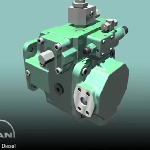
Variable Displacement piston pump, Piston, Swash plate, Pressure compensator, Bearing, Drive shaft
Page 47 :
TROUBLE SHOOTING, 43
Page 48 :
2005/2006 I., Hydraulic and Pneumatic Systems, 48, A typical hydraulic system, 1 – pump, 2 – oil tank, 3 – flow control valve, 4 – pressure relief valve, 5 – hydraulic cylinder, 6 – directional control valve, 7 – throttle valve
Page 49 :
2005/2006 I., Hydraulic and Pneumatic Systems, 49, Hydraulic Systems, Typical hydraulic system:
Page 50 :
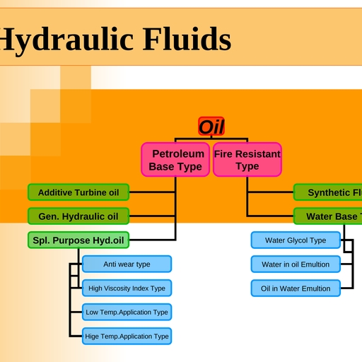
Hydraulic Fluids
Page 51 :
Limits of dust particle content
Page 52 :
System Cleanliness, Filter each change of oil to prevent the introduction of contamination., Provide continuous filtration to remove sludge, product of wear and corrosion that has generated during the life of system , Maintain an ISO cleanliness code 18/13 or cleaner. System cleanliness may be obtained through the use of OFP OFR or OFRS series filter, Seal the system to prevent the introduction of air born contamination
Page 53 :
Properties of Hydraulic Fluids, * Suitable Viscosity & Preferable high Viscosity , Index. , * Pouring Characteristic., * Lubrication Characteristic., * Chemical stability of add ivies, * Resistance to carbonizing due to heat, * Anti –rust & Anti –corrosive, * High shear strength, * Anti foam properties &very low compressibility, Oxidation stability
Page 54 :
NAS 1638, To measure cleanliness of Hydraulic oil, for instance 100 ml of Hydraulic oil is filtered through a filtration device., The number and size of dust particles caught in the Mile-pore Filter and examined by a microscope and there weight and size is measured and classified as shown in the Table.
Page 55 :
NAS 1638 Standards �Size of Dust Particle in Hydraulic oil (100 ml sample)
Page 56 :
Classification by weight, Highly contaminated oil is classified according their weight of dirt particle collected from 100 ml of oil sample by Mile-pore filter shown in the table
Page 57 :
Standard Maintenance Practice, Periodic checking of oil level in reservoir., Periodic checking of suction strainer., Return line filter elements to be change after 500 hours., Periodic analysis of oil sample to check the contamination level., Flushing of system after major breakdown and restart., Ensure proper type and quantity of spare are available in store., Mounting of magnets in reservoir to prevent entry of ferrous particle. , Do not mix two different grade / makes oil.
Page 58 :
Viscosity index of hydraulic oil, It is often measured by comparing the change in viscosity between 40° C and 100° C. The higher the viscosity index, the higher the resistance to change in viscosity. With hydraulic oil, a viscosity index of 100 is considered excellent (although automotive engine oil VI numbers can approach200).Mar 11, 2014, Viscosity (a fluid's resistance to flow) is rated at 0° F (represented by the number preceding the "W" [for Winter]) and at 212° F (represented by the second number in the viscosity designation). So 10W-30 oil has less viscosity when cold and hot than does 20W-50. Motor oil thins as it heats and thickens as it cools, Hydraulic fluid temperatures above 180°F (82°C) damage most seal compounds and accelerate degradation of the oil. While the operation of any hydraulic system at temperatures above 180°F should be avoided, fluid temperature is too high when viscosity falls below the optimum value for the hydraulic system's components.
Page 59 :
OIL FILTER
Page 61 :
. Filtration, ., UP STREAM, DOWN STREAM, BETA RATIO Bx = NUMBER PARTICLE (xN UPSTREAM / NUMBER PARTICLE (yN DOWN STREAM
Page 62 :
FILTRATION EFFICIENCY, N (%)= (100- 100/ Bx) , If BETA RATIO Bx is 2, that means FILTRATION EFFICIENCY (N) =50.00 % , , If BETA RATIO Bx is 20 that means FILTRATION EFFICIENCY (N) =95 %, , If BETA RATIO Bx is 75 that means FILTRATION EFFICIENCY (N) =98.67 %, , If BETA RATIO Bx is 100 that means FILTRATION EFFICIENCY (N) =99 %, , * If BETA RATIO Bx is 200 that means FILTRATION EFFICIENCY (N) =99.50 %, , If BETA RATIO Bx is 1000 that means FILTRATION EFFICIENCY (N) =99 .9%
Page 63 :
Hydraulic Accessories, Reservoir, Breather Filter, Fluid Level Indicator, Drive coupling, Pressure Gauge, Pulsation Damper, Gauge Isolator, Temperature Gauge, Temperature Swatch, Magnetic Tank cleaners, Float switch, Pressure Switch, Caster wheels, Mufflers
Page 64 :
Servo Valve, Servo valve may have infinitely positioned to provide control of both the amount and Direction of Fluid flow., The servo valve coupled with proper feed back sensing device provides very accurate control of the position velocity, acceleration of an actuator
Page 65 :
Servo Valve
Page 66 :
Comparison between Servo Valve and Proportional Valve
Page 67 :
Servo valve