Notes of Mechanical Engineering, Engineering physics Diffraction - Study Material
Page 1 :
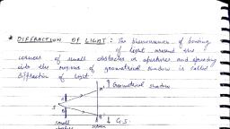
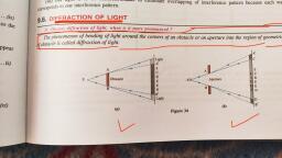
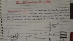
[CHAPTER 2°, , DIFFRACTION, , 2, , , , , , ) what ave the lypes oF dP and guee be difleencee hebucen Bern,, , due., , 2) ob m the condition abe py Ory maxima imbeitho Pec di PRo ifs y, , Single elit anddeve an ex preasion Bax caiich bs of Peete, , pax me ., , _ INTRODUCTION, , , , The wave nature of light is further confirmed by the optical phenomenon of, diffraction. The word ‘diffraction’ is derived from the Latin word diffractus, which means to break to pieces. It is common experience that waves bend around, obstacles placed in their path. When light waves encounter an obstacle, they bend, round the edges of the obstacle. This bending is predominant when the size of the, obstacle is comparable to the wavelength of light. The bending of light waves, around the edge of an obstacle is diffraction. It was first observed by Gremaldy., , 2.1 DIFFRACTION, , As shown in Fig. 2.1, when light falls on an obstacle then the corresponding, geometrical shadow on the screen should be completely dark. In practice, the, geometrical shadow consists of bright and dark fringes. These fringes are due, to the superimposition of bended light waves around the corners of an obstacle., The amount of bending depends upon the size of an obstacle and wavelength of, light., , , , , , , , , , Screen, , Light | A A!, —_>, —- Geometrical Shadow, —, , i BI, , B, , | Obstacle, , Figure 2.1 Diffraction, , When light falls on an obstacle whose size is comparable with the wavelength, of light then light bends around the edges or corners of an obstacle and enters
Page 2 :
Engineering Physics, , 22 @ iy, , into the geometrical shadow. This bending of light is known as diffraction. The, bright and dark fringes in the shadow forms a diffraction pattern., The diffraction phenomena are broadly classified into two types., , Fresnel diffraction, , To study diffraction, there should be a light source, obstacle and screen. In this, class of diffraction, the source and screen are placed at finite distances from the, obstacle. To study this diffraction, lenses are not necessary as the source and, screen are at a finite distance. This diffraction can be studied in the direction of, propagation of light. The incident wave fronts are either spherical or cylindrical., , Fraunhofer diffraction, , In this class of diffraction, the source and screen are placed at infinite distances, from the obstacle. Due to the above fact, we need lenses to study the diffraction., This diffraction can be studied in any direction. In this case, the incident wave, , front is plane., 2.1.1 Comparison Between Fresnel’s and Fraunhofer’s, Diffraction, , Fresnel’s Diffraction Fraunhofer Diffraction, , 1. For diffractions to occur the light source, and screen are at finite distance from, , the obstacle., , 1. For diffraction to occur, the light, source and screen are at {finite, distance from the obstacle., , 2... To Fa the diffraction, lenses 2. Mi-lenses are necessary to study the, ard Necessary. diffraction., , 3. Study of the diffraction is complicated. 3. Study of the diffraction is easy., , 4. Diffraction can be studied only in 4. Diffraction can be studied in any direction, the direction of propagations of light. of propagations of light., , 5. In this case, the incident wavefronts 5. In this case, the incidient wavefronts, , are either spherical or cylindrical. are plane., , , , 2.1.2 Difference Between Interference and Diffraction, , When two or more light waves superimpose then it causes intensity modifications, in the resultant light wave, which causes the interference phenomenon. In, diffraction, the bended light waves superimpose and cause intensity variations, in the form of a diffraction pattern. The diffraction phenomenon also involves, interference effect. Let us study the differences between interference and, , diffraction phenomena., , Interference Diffraction, , 1. It is due to superposition of two 1., different wavefronts originating from, , two coherent sources., , It is due to superposition of secondary, wavelets originating from the different parts, of the same wavefront., , Contd...
Page 3 :
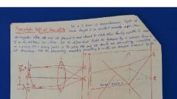
Diffraction 23, , Contd..., , , , 2. Interference bands are of equal width. 2. Diffraction bands decrease in their widths as, the order increases., , 3: All the bright fringes are of the same 3. The bright fringes are of varying intensity., intensity., , 4, All the dark fringes have zero intensity.4. The intensity of dark fringes is not zero., , 2.2 FRAUNHOFER DIFERACTION AT SINGLE SLIT, , Consider a slit AB of width ‘e’. Let a plane wave front WW’ of monochromatic, light of wavelength A propagating normally towards the slit is incident on it. The, diffracted light through the slit is focussed by means of a convex lens on a screen, placed in the focal plane of the lens. According to Huygen—Fresnel, every point, on the wave front in the plane of the slit is a source of secondary wavelets, which, spread out to the right in all directions. These wavelets travelling normal to the, slit, i.e., along the direction OP, are brought to focus at Py by the lens. Thus, Po, is a bright central image. The secondary wavelets travelling at an angle 0 with the, normal are focussed at-a point P, on the screen. Depending on path difference,, the point P, may have maximum or minimum intensities. To find intensity at P,,, let us draw the normal AC from A to the light ray at B., , , , Screen, , , , Plane, Wave Front, , Figure 2.2 Fraunhofer diffraction—single slit, , The path difference between the wavelets from A and B in the direction 6 is, , given by 4, path diff. = BC = AB sin 0=e sin 8, , corresponding phase diff. = = x path difference, , a, =e sin @, x é sin, , Let the width of the slit be divided into n equal parts and the amplitude of the, wave from each part is ‘a’. The phase difference between any two successive, , waves from these parts would be, , A [Total phase] = a [# esin 6| = d (say)
Page 4 :
Engineering Physics, 2.4, , Using the method of vector addition of amplitudes, the resultant amplitude, , , , , , , , is given by, _ asin nd/2, sin d/2, asin (me sin O/A), =, ‘sin (ze sin O/nA), = Sin @ where or= me sin O/A, sin o/n, =a sin (: o/n is very small), adn, =n 28h (ena=A), sin @, =A=5, i 2, Intensity 1-=R-A2 (S22) ay, , 2.2.1 Principal Maximum, The resultant amplitude R can be written in ascending powers of @ as, , Ala 242 2..], , Rao Oat eT, > 4 6, _ 2, a a, ? : Ss a a, , , , / will be maximum, when the value of R is maximum. For maximum value of, R, the negative terms must vanish, i.c., @= 0, , me sin 0, ee = 0, A, sin 6 =0, 6=0 (2), Then R=A, Dnax =R = A (3), , The condition @= 0 means th:, , at the maximum intensity j i, tior Sity is at Py and is, known as principal maximum. cei, , 2.2.2. Minimum Intensity Positions, / will be minimum, when sin ~@=0, , Q=47,427, 437, , a=+mnr, Ke sin @, —— =t+mn, , ZX
Page 5 :
Diffraction, eo iff @ 25, , esin @=+4mA, , (4), where m= 1, 2, 3.0..., , Thus, we obtain the points of minimum intensity on either side of the principal, maximum. For m = 0, sin @=0, which corresponds to principal maximum., 2.2.3 Secondary Maxima, , In between these minima, we get secondary maxima. The positions can be, , obtained by differentiating the expression of / w.r.t.@tand equating to zero. We, get, , fo z£le(eae), , = =0, da da a, 2sin@ a@cos a-si, Ar, Se Sees asin =, oe, , either sina =0 or acosa—sina=0, sin &@ =0 gives positions of minima., Hence the positions of secondary maxima are given by, acos @-sina =0, a=tang (5), , The values of @ satisfying the above equation are obtained graphically, by plotting the curves y = a and y = tan @ on the same graph. The points of, intersection of the two curves gives the values of a which satisfy the above, equation. The plots of y = @ and y = tan @ are shown in Fig. 2.3., , , , , , Figure 2.3 Plots of y= Qand y = tan @, , The points of intersections are, , @=0,43% 4 5a gh, 2 2, Substituting the above values in Eq. (1), we get the intensities in various, maxima., , @=0,Iy=A* (principal maximum)
 Learn better on this topic