Notes of ITI, Mechanic Diesel Engine ZCompleteBook2STT.pdf - Study Material
Page 1 :
MECHANIC DIESEL, NSQF LEVEL - 4, , 2nd Semester, TRADE THEORY, SECTOR: Automobile, , DIRECTORATE GENERAL OF TRAINING, MINISTRY OF SKILL DEVELOPMENT & ENTREPRENEURSHIP, GOVERNMENT OF INDIA, , NATIONAL INSTRUCTIONAL, MEDIA INSTITUTE, CHENNAI, Post Box No. 3142, CTI Campus, Guindy, Chennai - 600 032, (i), , Copyright @ NIMI Not to be Republished
Page 2 :
Sector, , : Automobile, , Duration : 1 - Years, Trades, , : Mechanic Diesel 2nd Semester - Trade Theory - NSQF LEVEL 4, , Copyright © 2018 National Instructional Media Institute, Chennai, First Edition:, , November 2018, , Copies: 1,000, , Rs. 180/-, , All rights reserved., No part of this publication can be reproduced or transmitted in any form or by any means, electronic or mechanical,, including photocopy, recording or any information storage and retrieval system, without permission in writing from the, National Instructional Media Institute, Chennai., , Published by:, NATIONAL INSTRUCTIONAL MEDIA INSTITUTE, P. B. No.3142, CTI Campus, Guindy Industrial Estate,, Guindy, Chennai - 600 032., Phone: 044 - 2250 0248, 2250 0657, 2250 2421, Fax : 91 - 44 - 2250 0791, email :
[email protected] ,
[email protected], Website: www.nimi.gov.in, (ii), , Copyright @ NIMI Not to be Republished
Page 3 :
FOREWORD, The Government of India has set an ambitious target of imparting skills to 30 crores people, one out of every, four Indians, by 2020 to help them secure jobs as part of the National Skills Development Policy. Industrial, Training Institutes (ITIs) play a vital role in this process especially in terms of providing skilled manpower., Keeping this in mind, and for providing the current industry relevant skill training to Trainees, ITI syllabus, has been recently updated with the help of Mentor Councils comprising various stakeholders viz. Industries,, Entrepreneurs, Academicians and representatives from ITIs., The National Instructional Media Institute (NIMI), Chennai, has now come up with instructional material to, suit the revised curriculum for Mechanic Diesel, 2nd Semester Trade Theory NSQF Level - 4 in, Automobile Sector under Semester Pattern. The NSQF Level - 4 will help the trainees to get an international, equivalency standard where their skill proficiency and competency will be duly recognized across the globe, and this will also increase the scope of recognition of prior learning. NSQF Level - 4 trainees will also get, the opportunities to promote life long learning and skill development. I have no doubt that with NSQF Level, - 4 the trainers and trainees of ITIs, and all stakeholders will derive maximum benefits from these Instructional, Media Packages IMPs and that NIMI's effort will go a long way in improving the quality of Vocational training, in the country., The Executive Director & Staff of NIMI and members of Media Development Committee deserve appreciation, for their contribution in bringing out this publication., Jai Hind, , RAJESH AGGARWAL, Director General/ Addl.Secretary, Ministry of Skill Development & Entrepreneurship,, Government of India., , New Delhi - 110 001, , (iii), , Copyright @ NIMI Not to be Republished
Page 4 :
PREFACE, The National Instructional Media Institute (NIMI) was established in 1986 at Chennai by then Directorate, General of Employment and Training (D.G.E & T), Ministry of Labour and Employment, (now under Directorate, General of Training, Ministry of Skill Development and Entrepreneurship) Government of India, with technical, assistance from the Govt. of Federal Republic of Germany. The prime objective of this Institute is to develop, and provide instructional materials for various trades as per the prescribed syllabus under the Craftsman, and Apprenticeship Training Schemes., The instructional materials are created keeping in mind, the main objective of Vocational Training under, NCVT/NAC in India, which is to help an individual to master skills to do a job. The instructional materials are, generated in the form of Instructional Media Packages (IMPs). An IMP consists of Theory book, Practical, book, Test and Assignment book, Instructor Guide, Audio Visual Aid (Wall charts and Transparencies) and, other support materials., The trade practical book consists of series of exercises to be completed by the trainees in the workshop., These exercises are designed to ensure that all the skills in the prescribed syllabus are covered. The trade, theory book provides related theoretical knowledge required to enable the trainee to do a job. The test and, assignments will enable the instructor to give assignments for the evaluation of the performance of a trainee., The wall charts and video clips are unique, as they not only help the instructor to effectively present a topic, but also help him to assess the trainee's understanding. The instructor guide enables the instructor to plan, his schedule of instruction, plan the raw material requirements, day to day lessons and demonstrations., IMPs also deals with the complex skills required to be developed for effective team work. Necessary care, has also been taken to include important skill areas of allied trades as prescribed in the syllabus., The availability of a complete Instructional Media Package in an institute helps both the trainer and, management to impart effective training., The IMPs are the outcome of collective efforts of the staff members of NIMI and the members of the Media, Development Committees specially drawn from Public and Private sector industries, various training institutes, under the Directorate General of Training (DGT), Government and Private ITIs., NIMI would like to take this opportunity to convey sincere thanks to the Directors of Employment & Training, of various State Governments, Training Departments of Industries both in the Public and Private sectors,, Officers of DGT and DGT field institutes, proof readers, individual media developers and coordinators, but for, whose active support NIMI would not have been able to bring out this materials., , R. P. DHINGRA, Chennai - 600 032, , EXECUTIVE DIRECTOR, , (iv), , Copyright @ NIMI Not to be Republished
Page 6 :
INTRODUCTION, TRADE THEORY, The manual of trade theory consists of theoretical information for the Second Semester course of the Mechanic, Diesel Trade. The contents are sequenced according to the practical exercise contained in the manual on Trade, practical. Attempt has been made to relate the theortical aspects with the skill covered in each exercise to, the extent possible. This co-relation is maintained to help the trainees to develop the perceptional capabilities, for performing the skills., The Trade theory has to be taught and learnt along with the corresponding exercise contained in the manual, on trade practical. The indicating about the corresponding practical exercise are given in every sheet of this, manual., It will be preferable to teach/learn the trade theory connected to each exercise atleast one class before, performing the related skills in the shop floor. The trade theory is to be treated as an integrated part of each, exercise., , Module 1, , Diesel engine over view, , 50 Hrs, , Module 2, , Diesel engine components, , Module 3, , Cooling & lubricating system, , 75 Hrs, , Module 4, , Intake and exhaust system, , 25 Hrs, , Module 5, , Diesel fuel system, , 75 Hrs, , Module 6, , Marine & stationary engine, , 25 Hrs, , Module 7, , Emission control system, , 25 Hrs, , Module 8, , Charging and Starting system, , 25 Hrs, , Module 9, , Trouble shooting, , 50 Hrs, , 175 Hrs, , Total, , 525 Hrs, , The material is not the purpose of self learning and should be considered as supplementary to class room, instruction, TRADE PRACTICAL, The trade practical manual is intented to be used in workshop . It consists of a series of practical exercises, to be completed by the trainees during the Second Semester course of the Mechanic Diesel trade, supplemented and supported by instructions/ informations to assist in performing the exercises. These, exercises are designed to ensure that all the skills in compliance with NSQF LEVEL - 4, The manual is divided into Nine modules. The distribution of time for the practical in the Eight modules are given, below., The skill training in the shop floor is planned through a series of practical exercises centred around some, practical project. However, there are few instances where the individual exercise does not form a part of project., While developing the practical manual a sincere effort was made to prepare each exercise which will be easy, to understand and carry out even by below average trainee. However the development team accept that there, is a scope for further improvement. NIMI, looks forward to the suggestions from the experienced training faculty, for improving the manual., (vi), , Copyright @ NIMI Not to be Republished
Page 7 :
CONTENTS, Exercise No., , Title of the Exercise, , Page No., , Module 1 : Diesel engine over view, 2.1.62, , 2.1.63, , 2.1.64, , 2.1.65, , Internal and external combustion engine, , 1, , Classification of engine, , 2, , Function of Diesel engine, , 4, , Function of spark ignition, , 6, , Main parts of Internal Combustion engine, , 10, , Direct and indirect fuel injection system, , 11, , Dashboard gauges, meters and warnings lights, , 16, , Gauges used in automobiles, , 18, , Starting and stopping methods of engine, , 20, , Procedure for dismantling of diesel engine from the vehicle, , 22, , Module 2 : Diesel engine components, 2.2.66, , Description and constructional feature of cylinder head, , 23, , 2.2.67, , Effect on size of intake and exhaust passages, , 26, , 2.2.68 & 2.2.70, , Valves, , 27, , valve operating mechanism, , 28, , Valve contructional features and valve timining, , 31, , Camshaft, , 35, , Camshaft drive mechanisms, , 35, , Piston and piston rings, , 38, , Piston ring, , 43, , Description & function of connecting rod, , 46, , Locking methods of piston pin, , 47, , 2.2.71, , 2.2.72 & 2.2.76, , 2.2.77, , (vii), , Copyright @ NIMI Not to be Republished
Page 8 :
Exercise No., , 2.2.78 & 2.2.82, , Title of the Exercise, , Page No., , Description and function of crankshaft, , 48, , Bearings, , 50, , Application bearing, failure of its causes and care of maintenance, , 52, , Crankshaft balancing, firing order of the engine, , 54, , Flywheel, , 56, , Vibration damper, , 56, , 2.2.85, , Timing gear drive, , 58, , 2.2.86, , Clutch, , 59, , 2.2.87 & 2.2.91, , cylinder block, , 62, , 2.2.92 & 2.2.94, , Engine assembling special tools, , 64, , Gas turbine, , 65, , 2.2.83 & 2.2.84, , Module 3 : Cooling & Lubricating system, 2.3.95 & 102, , Cooling and lubricating system, , 66, , Components of water cooling system, , 68, , Engine Lubricating system, , 72, , Oil pump & Filter, , 75, , Lubricant, , 77, , Module 4 : Intake and exhaust systen, 2.4.103 & 104, , 2.4.105 & 107, , Description of diesel induction and exhaust system, , 79, , Aircompressor, exhauster and turbo charger, , 79, , Turbocharger, , 81, , Air cleaner and air cooler, , 83, , Manifolds and silencer, , 84, , Mufflers, , 85, , (viii), , Copyright @ NIMI Not to be Republished
Page 9 :
Exercise No., , Title of the Exercise, , Page No., , Module 5 : Diesel fuel system, 2.5.108, , 2.5.109, 2.5.110 & 2.2.113, , 2.5.114, , Fuel and feed system, , 87, , Fuel feed pump and filter, , 88, , Carburettor systems, , 90, , Diesel fuel, , 94, , Fuel tank and fuel pipes, , 96, , Fuel filter, , 96, , Fuel feed pump, , 98, , Fuel injection pump, , 99, , Nozzles, , 101, , Electronic diesel control (EDC) system, , 105, , ECM Electronic control module (or) system, , 107, , Common rail diesel injection CRDI, , 108, , HEUI Hydraulically actuated electronically controlled unit injector, , 109, , Module 6 : Marine & stationary engine, 2.6.115 & 2.6.117, , Electro magnetic coupling different of starting on marine engine, , 115, , Auxiliary Engine Automation System, , 118, , Common rail system of marine engines, , 121, , Module 7 : Emission control system, 2.7.118 & 2.7.119, , 2.7.120, , Sources of Emission, , 125, , Vehicle emissions standards- Euro and Bharat, , 125, , Combustion chamber design, , 131, , Combustion process, , 132, , Characteristics and Effect of Hydrocarbons, , 133, , Hydrocarbons in exhaust gases, , 133, , Diesel particulate filters (DPF), , 133, , (ix), , Copyright @ NIMI Not to be Republished
Page 10 :
Exercise No., , Title of the Exercise, , Page No., , Source of Pollutants, , 135, , Crankcase emission control, , 136, , Exhaust gas recirculation (EGR) valve, , 137, , Evaporation emission control, , 139, , Catalytic converter, , 140, , Selective catalytic reduction(SCR), , 141, , EGR Vs SCR, , 142, , Module 8 : Charging and starting system, 2.8.121, , 2.8.122, , Alternator, , 143, , Differences Between Alternator And Dynamo, , 146, , Common troubles and remedies in alternator, , 147, , Starting motor circuit and constructional details, , 148, , Module 9 : Trouble shooting, 2.9.123, , Trouble shooting (causes and remedies), , (x), , Copyright @ NIMI Not to be Republished, , 152
Page 11 :
LEARNING / ASSESSABLE OUTCOME, On completion of this book you shall be able to, • Understand basics of engine types construction, working., • Dismantle & assemble of Diesel Engine from vehicle (LMV/HMV), along with other accessories (torqueing methods, handling parts.), • Overhaul, service and testing Diesel Engine, its parts and check, functionality., • Trace, Test & Repair cooling and Lubrication System of engine, (types of coolants and oils relevant to the engines)., • Trace & Test Intake and Exhaust system of engine. (cleaning egr, valves, exhaust inlet valves, ports and manifolds), • Service Diesel Fuel System and check proper functionality (calibration of mechanical and electronic pumps, checking injectors,, filters), • Plan & overhaul the stationary engine and Governor and check, functionality., • Monitor emission of vehicle and execute different operation to, obtain optimum pollution as per emission norms., • Carryout overhauling of Alternator and Starter Motor., • Diagnose & rectify the defects in LMV/HMV to ensure functionality, of vehicle, • Checking the condition of hoses, mounts, radiators and fans., • Electronic control diagnostics of CR engines., , (xi), , Copyright @ NIMI Not to be Republished
Page 12 :
SECONED SEMESTER, , Week, No., , 27-28, , 20-30, , SYLLABUS FOR MECHANIC DIESEL TRADE, , LearningOutcome, Reference, , Professional Skills, (Trade Practical), with Indicative hrs., , Duration: 06 Months, , Professional Knowledge, (Trade Practical), , Dismantle & assemble of, Diesel Engine from vehicle, (LMV/HMV) along with other, accessories., , 62. Identify the different parts of IC, Engine(10 hrs), 63. Identify the different parts in a, diesel engine of LMV/ HMV (10, hrs), 64. Perform practice on starting and, stopping of diesel engines., Observe and report the reading, of Tachometer, Odometer,, temp and Fuel gauge under, ideal and on load condition. (10, hrs), , Introduction to Engine:, - Description of internal & external, combustion, engines,, Classification of IC engines,, Principle & working of 2&4stroke, diesel, engine, (Compression ignition Engine, (C.I)),, - Principle of Spark Ignition, Engine(SI), differentiate between, 2-stroke and 4 stroke, C.I engine, and S.I Engine,, - Main Parts of IC Engine, - Direct injection and indirect, injection, Technical terms used, in engine, Engine specification., - Study of various gauges/, instrument on a dash board of a, vehicleSpeedometer,, Tachometer, Odometer and Fuel, gauge, and Indicators such as, gearshift position, Seat belt, warning light, Parking-brakeengagement warning light and an, Enginemalfunction light., - Different type of starting and, stopping method of Diesel, Engine, - Procedure for dismantling of, diesel engine from a vehicle., , Overhaul & service Diesel, Engine, its parts and check, functionality., , 65. Practice on dismantling Diesel, engine of LMV/HMV as per, procedure. (20 hrs), 66. Perform Overhauling of cylinder, head assembly, Use of service, manual for clearance and other, parameters,(10 hrs), 67. Perform practice on removing, rocker arm assembly manifolds., (07 hrs), 68. Perform practice on removing the, valves and its parts from the, cylinder head, cleaning. (07 hrs), 69. Inspection of cylinder head and, manifold surfaces for warping,, cracks and flatness. Checking, valve seats & valve guide –, Replacing the valve if necessary., (07 hrs), , Diesel Engine Components:, - Description and Constructional, feature of Cylinder head,, Importance of Cylinder head, design,, - Type of Diesel combustion, chambers,, - Effect on size of Intake &, exhaust passages, Head, gaskets., - Importance of Turbulence, Valves & Valve Actuating, Mechanism - Description and Function of, Engine Valves, different types,, materials,, - Type of valve operating, mechanism, Importance of Valve, seats, Valve seats inserts in, cylinder heads,, , (xii), , Copyright @ NIMI Not to be Republished
Page 13 :
31, , 32, , -do-, , -do-, , 70.Check leaks of valve seats for, leakage – Dismantle rocker, shaft assembly -clean & check, rocker shaft-and levers, for wear, and cracks and reassemble. (07, hrs), 71. Check valve springs, tappets,, push rods, tappet screws and, valve stem cap. Reassembling, valve parts in sequence, refit, cylinder head and manifold &, rocker, arm, assembly,, adjustable valve clearances,, starting, engine, after, adjustments. (12 hrs), , - importance of Valve rotation,, Valve stem oil seals, size of, Intake valves, Valve trains, Valvetiming diagram, concept of, Variable valve timing., - Description of Camshafts &, drives ,, - Description of Overhead, camshaft (SOHC and DOHC),, importance of Cam lobes,, Timing belts & chains, Timing, belts & tensioners., , 72. Perform Overhauling piston and, connecting rod assembly. Use of, service manual for clearance and, other parameters (05 hrs), 73. Perform Practice on removing oil, sump and oil pump – clean the, sump., 74. Perform removing the big end, bearing, connecting rod with the, piston. (05 hrs), 75. Perform removing the piston rings;, Dismantle the piston and, connecting rod. Check the side, clearance of piston rings in the, piston groove & lands for wear., Check piston skirt and crown for, damage and scuffing, clean oil, holes. (05 hrs), 76. Measure -the piston ring close gap, in the cylinder, clearance between, the piston and the liner, clearance, between crank pin and the, connecting rod big end bearing., (05 hrs), 77. Check connecting rod for bend and, twist. Assemble the piston and, connecting rod assembly. (05 hrs), , - Description & functions of, different types of pistons, piston, rings and piston pins and, materials., - Used, recommended, clearances for the rings and its, necessity precautions while, fitting rings, common troubles, and remedy., - Compression ratio., - Description & function of, connecting rod, - importance, of big- end split obliquely, - Materials used for connecting, rods big end & main bearings., Shells piston pins and locking, methods of piston pins., , 78. Perform Overhauling of crankshaft,, Use of service manual for, clearance and other parameters, (05 hrs), 79. Perform removing damper pulley,, timing gear/timing chain, flywheel,, main bearing caps, bearing shells, and crankshaft from engine(05 hrs), 80. Inspect oil retainer and thrust, surfaces for wear. (05 hrs), 81. Measure crank shaft journal for, wear, taper and ovality. (05 hrs), , (xiii), , -, , Description and function of Crank, shaft, camshaft,, - Engine bearings- classification, and location – materials used &, composition of bearing materialsShell bearing and their, advantages- special bearings, material for diesel engine, - Application bearing failure & its, causes-care & maintenance., - Crank-shaft balancing, firing, order of the engine., , Copyright @ NIMI Not to be Republished
Page 14 :
82. Demonstrate crankshaft for, fillet radii, bend & twist. (05, hrs), , 33, , 34, , 35, , 36-38, , -, , Description and function of the, fly wheel and vibration damper., - Crank case & oil pump, gears, timing mark, Chain sprockets,, chain tensioner etc., - Function of clutch & coupling, units attached to flywheel., , 83. Inspect flywheel and mounting flanges,, spigot and bearing.(05 hrs), 84. Check vibration damper for defect. (02, hrs), 85. Perform removing cam shaft from, engine block, Check for bend & twist, of camshaft. Inspection of cam lobe,, camshaft journals and bearings and, measure cam lobe lift. (07 hrs), 86. Fixing bearing inserts in cylinder, block & cap check nip and spread, clearance & oil holes & locating lugs, fix crank shaft on block-torque bolts, - check end play remove shaft - check, seating, repeat similarly for, connecting rod and Check seating, and refit. (11 hrs), , -do-, , -do-, , -do-, , Trace, Test &, Repair Cooling and, Lubrication System, of engine., , 87. Perform cleaning and checking of, cylinder blocks. (04 hrs), 88. Surface for any crack, flatness measure, cylinder bore for taper & ovality, clean, oil gallery passage and oil pipe line., (05 hrs), 89. Perform bore - descale water passages, and examine. (05 hrs), 90. Removing cylinder liners from scrap, cylinder block. (04 hrs), 91. Perform practice in measuring and, refitting new liners as per maker’s, recommendations precautions while, fitting new liners. (07 hrs), , - Description of Cylinder block,, - Cylinder block construction,, - Different type of Cylinder sleeves, (liner)., , 92. Perform reassembling all parts of, engine in correct sequence and torque, all bolts and nuts as per workshop, manual of the engine. (12 hrs), 93. Perform testing cylinder compression,, Check idle speed. (08 hrs), 94. Perform removing & replacing a cam, belt, and adjusting an engine drive belt,, replacing an engine drive belt. (05 hrs), , -, , 95. Perform practice on checking &top up, coolant, draining & refilling coolant,, checking / replacing a coolant hose. (10, hrs) 96. Perform test cooling system, pressure. (05 hrs), 97. Execute on removing & replacing, radiator/ thermostat check the radiator, pressure cap. (10 hrs), 98. Test of thermostat. (5 hrs), 99. Perform cleaning & reverse flushing. (10, hrs), , Need for Cooling systems, - Heat transfer method, Boiling, point & pressure,, - Centrifugal force,, - Vehicle coolant properties and, recommended change of, interval,, - Different type of cooling, systems,, , (xiv), , Engine assembly procedure, with aid of special tools and, gauges used for engine, assembling., - Introduction to Gas Turbine,, Comparison of single and two, stage turbine engine,, - Different between gas turbine, and Diesel Engine., , Copyright @ NIMI Not to be Republished
Page 15 :
Basiccoolingsystem, 100.Perform overhauling water pump and, components, refitting. (10 hrs), - Radiator, Coolant hoses, 101.Perform checking engine oil, draining, - Water pump,, engine oil, replacing oil filter, & refilling, - Cooling, system, engine oil (10 hrs), thermostat, Cooling fans,, 102. Execute overhauling of oil pump, oil, - Temperature indicators,, coolers, air cleaners and air filters and, - Radiator pressure cap,, adjust oil pressure relief valves, repairs to, Recovery, system,, oil flow pipe lines and unions if necessary., Thermoswitch., (15 hrs), Need for lubrication, system,, - Functions of oil, Viscosity, and its grade as per SAE ,, - Oil additives, Synthetic, oils, The lubrication, system, Splash system,, - Pressure system, - Corrosion/noise reduction, in the lubrication system., - Lubrication, system, components, - Description and function of, Sump, Oil collection pan,, Oil tank, Pickup tube,, - different type of Oil pump, & Oil filters Oil pressure, relief valve, Spurt holes &, galleries, Oil indicators, Oil, cooler., , 39, , Trace & Test Intake 103. Execute dismantling air compressor and, exhauster and cleaning all parts and Exhaust system, measuring wear in the cylinder,, of engine., reassembling all parts and fitting them in, the engine. (6 hrs), 104. Execute dismantling & assembling of, turbocharger, check for axial clearance as, per service manual. (05 hrs), 105.Examine exhaust system for rubber, mounting for damage, deterioration and out, of position; for leakage, loose connection,, dent and damage; (05 hrs), 106. Perform practice on exhaust manifold, removal and installation, practice on, Catalytic converter removal and installation., (05 hrs), 107.Check Exhaust system for rubber mounting, for damage, deterioration and out of position;, for leakage, loose connection, dent and, damage. (04 hrs), , (xv), , Intake & exhaust systems–, - Description of Diesel, induction & Exhaust, systems. Description &, function, of, air, compressor, exhauster,, Supercharger,, Intercoolers,, turbo, charger, variable turbo, charger mechanism., Intake system components- Description and function, of Air cleaners, Different, type, air, cleaner,, Description of Intake, manifolds and material,, Exhaustsystem components- Description and function, of Exhaust manifold,, Exhaustpipe, Extractors,, Mufflers-Reactive,, absorptive, Combination, of Catalyticconverters,, Flexible connections,, Ceramic coatings, Backpressure,, - Electronic mufflers., , Copyright @ NIMI Not to be Republished
Page 16 :
40-42, , Service Diesel Fuel, System and check, proper functionality., , 108. Perform work on removing, &cleaning fuel, t a n k s ,, checking leaks in the fuel lines. (10, hrs), 109. Perform soldering & repairing pipe, lines and Unions, brazing nipples to, high pressure line studying the fuel, feed system in diesel engines,, draining of water separators. (10 hrs), 110.Execute overhauling of Feed Pumps, (Mechanical & Electrical). (10 hrs), 111.Perform bleeding of air from the fuel, lines, servicing primary & secondary, filters. (10 hrs), 112. Execute removing a fuel injection, pump from an engine-refit the pump, to the engine re- set timing - fill, lubricating-oil start and adjust slow, speed of the engine. (15 hrs), 113.Execute overhauling of injectors and, testing of injector. (10 hrs), 114. General maintenance of Fuel, Injection, Pumps (FIP). (10 hrs), , Fuel Feed System in IC, Engine(Petrol & Diesel), - Gravity feed system, Forced, feed system, main parts,, Fuel Pumps- Mechanical &, Electrical Feed Pumps., - Knowledge about function,, working & types of, Carburettor., Diesel Fuel Systems, - Description and function of, Diesel fuel injection, fuel, characteristics, concept of, Quiet diesel technology, &Clean diesel technology., Diesel fuel system, components, - Description and function of, Diesel tanks & lines, Diesel, fuel filters, water separator,, Lift pump, Plunger pump,, Priming pump,, - Inline injection pump,, Distributor-type injection, pump, Diesel injectors, Glow, plugs, Cummins & Detroit, Diesel injection., Electronic Diesel control- Electronic Diesel control, systems, Common Rail, Diesel Injection (CRDI), system,, hydraulically, actuated electronically, controlled unit injector, (HEUI) diesel injection, system. Sensors, actuators, and ECU (Electronic Control, Unit) used in Diesel Engines., , 43, , Plan & overhaul the, stationary engine and, Governor and check, functionality., , 115. Execute Start engine adjust idling, speed and damping device in, pneumatic governor and venture, control unit checking. (06 hrs), 116. Verify performance of engine with, off load adjusting timings. Start, engine- adjusting idle speed of the, engine fitted with mechanical, governor checking- high speed, operation of the engine. (07 hrs), 117. Check performance for missing, cylinder by isolating defective, injectors and test- dismantle and, replace defective parts and, reassemble and refit back to the, engine. (12 hrs), , Marine & Stationary Engine:Types,, - double acting engines,, opposed piston engines,, starting systems, cooling, systems,, lubricating, systems, supplying fuel oil,, hydraulic coupling,, - Reduction gear drive,, electromagnetic coupling,, - Electrical drive, generators, and motors, supercharging., , (xvi), , Copyright @ NIMI Not to be Republished
Page 17 :
44, , 21.. Monitor emission of, vehicle and execute, different operation to obtain, optimum pollution as per, emission norms., , 118. Monitor emissions procedures by, use of Engine gas analyser or, Diesel smoke meter. (10 hrs), 119.Checking & cleaning a Positive, crank case ventilation (PCV) valve., Obtaining & interpreting scan tool, data. Inspection of EVAP canister, purges system by use of scan Tool., (10 hrs), 120. EGR /SCR Valve Remove and, installation for inspection. (05 hrs), , Emission Control:- Vehicle, emissions, - Standards- Euro and Bharat, II, III, IV, V Sources of, emission, Combustion,, Combustion chamber design., Types of emissions:, - Characteristics and Effect of, Hydrocarbons, Hydrocarbons, in exhaust gases, Oxides of, nitrogen, Particulates, Carbon, monoxide, Carbon dioxide,, Sulphur content in fuels, Description of Evaporation, emission control, Catalytic, conversion, Closed loop,, Crankcase emission control,, - Exhaust gas recirculation, (EGR) valve, controlling airfuel ratios, Charcoal storage, devices, Diesel particulate, filter (DPF). Selective, Catalytic, Reduction (SCR),, EGR VS SCR, , 45, , Carryout overhauling of, Alternator and Starter Motor, , 121. Perform removing alternator from Basic Knowledge about DC, Generator & AC Generator., vehicle dismantling, cleaning, Constructional details of, checking for defects, assembling, Alternator, and testing for motoring action of, alternator & fitting to vehicles. (15 - Description of charging circuit, operation of alternators,, hrs), regulator unit, ignition warning, 122. Practice on removing starter motor, lamp- troubles and remedy in, Vehicle and overhauling the starter, charging system., motor, testing of starter motor (10, Description, of starter motor, hrs), circuit,, - Constructional details of, starter motor solenoid, switches, common troubles, and remedy in starter circuit., , 46-47, , 23. Diagnose & rectify the, defects in LMV/HMV to, ensure functionality of, vehicle., , 123. Execute troubleshooting in LMV/, HMV for Engine Not starting –, Mechanical & Electrical causes,, High fuel consumption, Engine, overheating,, Low, Power, Generation, Excessive oil, consumption, Low/High Engine Oil, Pressure, Engine Noise. (50 hrs), , (xvii), , Troubleshooting :, Causes and remedy for, - Engine, Not, starting, Mechanical & Electrical, causes,, - High fuel consumption,, Engine overheating,, - Low Power Generation, Excessive oil consumption,, - Low/High Engine Oil, Pressure, Engine Noise., , Copyright @ NIMI Not to be Republished
Page 18 :
49-50, , In-plant training / Project work Projects viz., a. Overhauling of Pressure Lubrication system, b. Maintenance of cooling system., c. Overhauling of FIP., d. Cleaning & Testing of Injectors., e. Overhauling of Alternator, f. Overhauling of Starter Motor, g. Study on Diagnosis Tool/Scanner Tool for ECU of CRDI engine, , 51, , Revision, , 52, , Examination, , (xviii), , Copyright @ NIMI Not to be Republished
Page 19 :
Automobile, Related Theory for Exercise 2.1.62, Mechanic Diesel - Diesel engine over view, Internal and external combustion engine, Objectives : At the end of this lesson you shall be able to, • type of heat engine, • state the internal and external combusion engine, • difference between an internal and external combusion engine., Types of heat engines, 1 External combusion engine, Steam engine, 2 Internal combusion engine, , Rotary, , Piston type, , Reciprocating, piston engine, , Rotary piston, engine, (Experimental), , Free piston engine, (At preliminary, stage), , Diesel engine, , Petrol engine, , Two, Stroke, , Gas Turbine, , Four, Stroke, , Two, Stroke, , Four, Stroke, , As indicated above, modern automobile engines are:, With regard to their construction and operation:, i, , Piston type, , ii Rotary, iii Turbine, Internal combusion engine, , External combusion engine, , Internal combusion engine means, that combusion takes, place inside the cylinder, this definition including the two, stroke and four stroke engine, spark ignition and, compression ignition engine, wrankle, austine and jet, engines are also i.e engine., , External combusion engine is that type of engine in which, combusion takes place outside the engine cylinder. ex:, steam engine., , Copyright @ NIMI Not to be Republished, , 1
Page 20 :
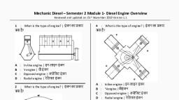
., , Difference between internal and external combusion engine, Sl.No, , Internal combusion engine, , External combusion engine, , 1, , Occupies less space., , Occupies more space., , 2, , Lighter in weight., , Heavier in weight., , 3, , High speed engine., , Slow speed engine., , 4, , Combusion of fuel takes palce inside the, engine., , Combusion of fuel takes palce inside the engine., , 5, , Fuels used in when engine is not running., , Soild or liquid fuels used to form steam., , 6, , No loss of fuel when engine is not running., , Fuel has to burn even when the engine is not, running for small halts., , 7, , Could be started or stopped at will., , Cannot be started unless steam is prepared, which takes much time., , 8, , Temperature produced inside the cylinder, is too high., , Works at comparatively low temperature., , 9, , Cooling arrangement necessary., , No cooling of the cylinders required. Rather, it is steam jacketed., , 10, , Single acting., , Mostly double acting., , 11, , Exhause gas temperature as high as 300°C., , The temperature of exhaust steam is quite low., , 12, , Thermal efficiency of diesel engine up to 40%., , Thermal efficiency up to 24% as that of petrol engine., , 13, , No needs boiler, furnace or condenser., , Boilder, furnace and condenser are must., , Classification of engine, Objective: At the end of this lesson you shall be able to, • state the classification of engines., Engines are classified according to the following factors., Number of cylinders, Single cylinder, Multi cylinder, Arrangements of cylinders, In this type, the cylinders are arranged in one line. The, length of the crankshaft is longer than that of the other, types of engines, and hence a limited number of cylinders, are used. Better balancing and more uniform torque is, obtained in this type., , In-line engine (Fig 1), `V' shape engine (Fig 2), Opposed engine (Fig 3), Horizontal engine, , V engines, , Radial engine (Fig 4), Vertical engine, Types of engines as per cylinder arrangement, In-line engines, , 2, , In this type, the cylinders are arranged in V shape at an, angle, of usually 60°. This engine is more economical and, compact. For multi-cylinder engines, the length of the, crankshaft is much shorter than that of the in- line engine., In this type, the engine height is also lower than it is in the, in-line engine., , Automobile: Mechanic Diesel (NSQF Level-5) - R.T. for Exercise 2.1.62, , Copyright @ NIMI Not to be Republished
Page 21 :
Types of engine as per number of cylinders, Single cylinder engines, An engine which has only one cylinder is called a single, cylinder engine. Since it is a single cylinder engine it, cannot develop more power. It is normally used only in two, wheelers like scooters and motor cycles., Multi cylinder engines, These engines have more than one cylinder. Two-cylinder, engines are usually used in tractors. Three or four cylinder, engines are used in cars, jeeps and other vehicles. In, heavy vehicles six-cylinder engines are used. A greater, number of cylinders gives smoother engine operation., Opposed engines, , Types of fuel used, , In this type the cylinders are arranged horizontally opposite, to each other. This provides better mechanical balance., This type of engine can run smoothly even at a much higher, speed. It also gives higher output. The length of the engine, is too much, and therefore engine has to be placed in the, transverse direction in the vehicle., , Petrol, Diesel, Types of valve arrangements, `I' head engine, `F' head engine, `L' head engine, `H' head engine, `T' head engine, , Radial engines, , Application of engine, Constant speed engine, Variable speed engine, Cooling system, Air cooled engine, Water cooled engine, Strokes of engine, Four-stroke engine, Two-stroke engine, Rotary engine, , In this type, the cylinders are arranged radially. This type, of engine is shorter, lighter and more rigid. Since it is rigid,, a higher engine speed is possible and a higher combustion, pressure can be obtained. This leads to high fuel efficiency., The radial type engines are used mostly in aeroplanes., , Automobile: Mechanic Diesel (NSQF Level- 4) - R.T. for Exercise 2.1.62, , Copyright @ NIMI Not to be Republished, , 3
Page 22 :
Function of Diesel engine, Objectives : At the end of this lesson you shall be able to, • describe the function of a two-stroke diesel engine, • describe the function of a four-stroke diesel engine., Two strke diesel engine:, , Four-stroke engine, , To produce power in a two stroke engine the following, operation take place in the sequence given., , To produce power in a four-stroke engine the following, operations take place in the sequence given., , First stroke: Piston at BDC the scavenging port and outlet valve open (Fig 1). A root blower sucks in pure air and, presses it through the scavenging port into the cylinder., The tangential layout of the scavenging port brings the air, into a turbulent motion. The cylinder is completely flushed, out in the direct current and filled with fresh air. The exhaust gases flow out towards the outlet valve., , Suction stroke, , As the piston moves up from BDC the scavenging port, and outlet valve closed. The piston compresses the fresh, air to the compression chamber. The air temperature increases intensively., Second stroke: Piston at TDC (Fig 2) scavenging port, and outlet valve closed. The fuel is directly injected into, the cylinder with the help of a fuel injection pump and an, injector fitted in the cylinder head. The fuel gets vaporised, into an ignitable fuel air mixture by the hot air. After attaining the ignition temperature the mixture gets automatically ignited and burns. The heat increases the pressure, in the combustion chamber. The gases get expanded and, push the piston to the bottom dead centre., , 4, , The piston moves from TDC to BDC (Fig 3). A vacuum is, created inside the cylinder. The inlet valve opens while the, exhaust valve remains closed. The charge (air/air-fuel, mixture) enters the cylinder., , Compression stroke, The inlet valve closes. The exhaust valve remains closed., The piston moves from BDC to TDC (Fig 4). The charge (air/, air-fuel mixture) is compressed.The pressure and, temperature rise., , Automobile: Mechanic Diesel (NSQF Level- 4) - R.T. for Exercise 2.1.62, , Copyright @ NIMI Not to be Republished
Page 23 :
Power stroke, , Exhaust stroke, , At the end of compression stroke diesel fuel is injected into, the hot compressed air in the combusion chamber; result, in instances burning of diesel with an explosion the gas, expand for is the piston down and power is produced and, pressure develops inside the cylinder. The gas expands, and the piston is forced down from TDC to BDC (Fig 5). Both, the valves remain closed. Power is supplied to the flywheel., , The inlet valve remains in the closed position. The exhaust, valve opens, the piston moves from BDC to TDC (Fig 6) due, to the energy stored in the flywheel. The burnt gases inside, the cylinder go out through the exhaust valves. At the end, of the stroke the exhaust valve closes., The cycle of suction, compression power and exhaust are, repeated. In this type of engines one power stroke is, obtained in two revolutions of the crankshaft., , Automobile: Mechanic Diesel (NSQF Level- 4) - R.T. for Exercise 2.1.62, , Copyright @ NIMI Not to be Republished, , 5
Page 24 :
Automobile, Related Theory for Exercise 2.1.63, Mechanic Diesel - Diesel engine over view, Function of spark ignition, Objectives : At the end of this lesson you shall be able to, • describe the function of a two-stroke engine, • describe the function of a four-stroke engine, • differentiate between a four-stroke and a two-stroke engine, • explain an OTTO cycle, • explain a diesel cycle., Two-Stroke spark ignition engines, To produce power in two stroke engine the following, operations take place in the sequence given., First stroke (Suction and compression), , As the piston moves up from BDC,(Fig 1) it closes the inlet, port (1), the exhaust port (3) and the transfer port (2)., Further upward movement of the piston results in, compressing the mixture in the cylinder and opening of the, inlet port (1). The upward motion of the piston creates a, partial vacuum inside the crank-case below the piston, and, the air/fuel mixture is drawn into the crank-case through the, inlet port (I). The exhaust and transfer ports remain closed, during the operation of the upward stroke and the charge, which reached above the piston during the previous stroke, is compressed., , Second stroke (power and exhaust), The piston is forced downward from the TDC (Fig 2). During, this stroke the exhaust port opens and burnt gases escape, into the atmosphere., , Further downward movement of the piston opens the, transfer port and allows the partially compressed mixture,, received during the previous stroke, to reach the combustion, chamber from the crankcase., The piston head has a special shape. It deflects a fresh, change of fuel mixture up into the cylinder. The mixture, flows down and pushes the burnt gas out. Through the, exhaust port. This process is called scavenging. Once the, flywheel has completed one revolution, the cycle is repeated., In this engine one power stroke is obtained in each, revolution of the crankshaft., , At the end of this stroke the mixture is ignited by an electric, spark (4). This causes the pressure to rise., , 6, , Copyright @ NIMI Not to be Republished
Page 25 :
Spark ignition (Fig 3), , Power stroke, , In a spark ignition (SI) engine, petrol is used as fuel. During, the suction stroke the air and fuel mixture is sucked into the, cylinder. The quantity of the mixture is metered by the, carburettor according to the load and speed. The ratio of, air/fuel mixture is also metered by the carburettor. During, the compression stroke, this air/fuel mixture is ignited by, the spark and the mixture is burnt. It raises the pressure of, the gas above the piston. The piston is forced down and, this power is supplied to the flywheel. During the exhaust, stroke burnt gases escape through the exhaust port/valve., , The charge is ignited and pressure develops inside the, cylinder. The gas expands and the piston is forced down, from TDC to BDC (Fig 6). Both the valves remain closed., Power is supplied to the flywheel., , In this type of engine the compression ratio is low., , Exhaust stroke, The inlet valve remains in the closed position. The exhaust, valve opens, the piston moves from BDC to TDC (Fig 7) due, to the energy stored in the flywheel. The burnt gases inside, the cylinder go out through the exhaust valves. At the end, of the stroke the exhaust valve closes., , Four-stroke spark ignition engine, , The cycle of suction, compression power and exhaust are, repeated. In this type of engines one power stroke is, obtained in two revolutions of the crankshaft., , To produce power in a four-stroke engine the following, operations take place in the sequence given., Suction stroke, The piston moves from TDC to BDC (Fig 4). A vacuum is, created inside the cylinder. The inlet valve opens while the, exhaust valve remains closed. The charge (air/air-fuel, mixture) enters the cylinder., Compression stroke, The inlet valve closes. The exhaust valve remains closed., The piston moves from BDC to TDC (Fig 5). The charge (air/, air-fuel mixture) is compressed. The pressure and, temperature rise., , Automobile: Mechanic Diesel (NSQF Level- 4) - R.T. for Exercise 2.1.63, , Copyright @ NIMI Not to be Republished, , 7
Page 26 :
Comparison between four-stroke engine and two-stroke engine, Four-stroke engine, , 8, , Two-stroke engine, , Four operations (suction, compression, power and, exhaust) take place in the four strokes of the piston., , The four operations take place in two strokes of the piston., , It gives one power stroke in the four strokes, i.e in two, revolutions of the crankshaft. As such three strokes are, idle strokes., , The power stroke takes place in every two strokes i.e., one power stroke for one revolution of the crankshaft., , Due to more idle strokes and non-uniform load on the, crankshaft, a heavier flywheel is required., , The engine has more uniform load as every time the, piston comes down it is the power stroke. As such a, lighter flywheel is used., , The engine has more parts such as valves and its, operating mechanism. Therefore, the engine is heavier., , The engine has no valves and valve-operating mechanism, therefore it is lighter in weight., , The engine is costlier as it has more parts., , The engine is less expensive as it has a lesser number, of parts., , The engine efficiency is more as the charge gets, completely burnt out. Consequently the fuel efficiency, is more., , The engine efficiency is less. A portion of the chargescapes, through the exhaust port, and because of this, the fuel, efficiency is less., , Automobile: Mechanic Diesel (NSQF Level- 4) - R.T. for Exercise 2.1.63, , Copyright @ NIMI Not to be Republished
Page 27 :
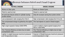
Comparison between S.I and C.I. Engine, SI engine, , CI engine, , Petrol is used as fuel., , Diesel is used as fuel., , During the suction stroke air and fuel mixture is, sucked in., , During the suction stroke air alone is sucked in., , Compression ratio is low. (Max. 10:1), , Compression ratio is high. (Max. 24:1), , Compression pressure is low. (90 to 150 PSI), , Compression pressure is high. (400 to 550 PSI), , Compression temperature is low., , Compression temperature is high., , It operates under constant volume cycle (otto cycle)., , It operates under constant pressure cycle (diesel cycle)., , Fuel is ignited by means of an electric spark., , Fuel is ignited due to the heat of the highly compressed, air. Combustion takes place at constant pressure., , A carburettor is used to atomize, vaporize and meter, the correct amount of fuel according to the requirement., , Fuel injection pumps and atomizers are used to inject, metered quantities of fuel at high pressure according to, the requirement., , Less vibration, and hence, smooth running., , More vibration, and hence, rough running and more noisy., , Engine weight is less., , Engine weight is more., , It emits carbon monoxide. (CO), , It emits carbon dioxide. (CO2), , Otto Cycle, , The gas expands during the power stroke (4-5), reducing, both pressure and temperature., Heat is rejected at constant volume. (5-2), Burnt gases exhaust when piston moves from BDC to TDC., (2-1), Diesel Cycle, , 1-2, 2-3, 3-4, 4-5, 5-2-1, , -, , Suction, Compression, Heat addition, Power, Exhaust, , In otto cycle engine,(Fig 8) combustion takes place at, constant volume., Suction takes place at a pressure below atmospheric, pressure when piston moves from TDC to BDC. (1-2), Compression takes place when piston moves from BDC to, TDC. (2-3), Fuel mixture is ignited by introducing a spark at constant, volume. (3-4), , 1-2, 2-3, 3-4, 4-5, , -, , Suction, Compression, Heat addition, Power, , Suction takes place at (Fig 9) pressure below atmospheric, pressure when piston moves from TDC to BDC. (1-2), Compression takes place when piston moves BDC to TDC., (2-3) (Both the valves closed)., , Automobile: Mechanic Diesel (NSQF Level- 4) - R.T. for Exercise 2.1.63, , Copyright @ NIMI Not to be Republished, , 9
Page 28 :
Fuel is sprayed at high pressure and ignited by hot, compressed air (3-4), and this process takes place at, constant pressure., , Heat is rejected at constant volume. (5-2), Burnt gases exhaust when piston moves from BDC to, TDC. (2-1), , Fuel ignites, pressure of burnt gas increases, gas expands, and piston is forced from TDC to BDC. (4-5), , Main parts of Internal Combustion engine, Objectives : At the end of this lesson you shall be able to, • location of an engine parts fitting., Internal combustion engine parts, Internal combustion engine’s function is accomated with, the different types of components and it is connected in, outer JPG & inside of the engine., , 27 Connecting rod, 28 Crank shaft, , Name of the components (Fig 1, 2 & 3), , 29 Remove the timing gear and chain (22). (Notedown timing marks.), , 1 Air compressor, , 30 Remove the cam shaft, , 2 F.I.P, , 31 Remove the oil sump (23), , 3 Injector, , 32 Disconnect the oil pipes from the oil pump., , 4 Air cleaner, , 33 Remove the oil pump and strainer (24), , 5 High pressure fuel, , 34 Remove the oil filter, , 6 Fly wheel, , 35 Remove the connecting rod caps. (Note down Nos. on, the caps), , 7 Oil filter, , 36 Remove the piston (21) and connecting rod (27) from, engine. (Note down the marks/Nos. on the piston), , 8 Fuel filter, 9 Fan belt, , 37 Remove the main bearing caps. (Note down them No., on the caps), , 10 Alternator, 11 Self starter, 12 Water pump, 13 Cam shaft, 14 Inlet manifold, 15 Exhaust manifold, 16 Valve door (cover), 17 Rocker assembly, 18 Push rod, 19 Tappets, 20 Cylinder head, 21 Piston, 22 Turning chain, 23 Oil sump, 24 Strainer, 25 Fly wheel housing, 26 Dip stick, 10, , Automobile: Mechanic Diesel (NSQF Level- 4) - R.T. for Exercise 2.1.63, , Copyright @ NIMI Not to be Republished
Page 29 :
Direct and indirect fuel injection system, Objectives : At the end of this lesson you shall be able to, • state the function of direct fuel injection, • state the function of indirect fuel injection., Direct Fuel Injection Works (Fig 1), Gasoline engines work by sucking a mixture of gasoline, and air into a cylinder, compressing it with a piston, and, igniting it with a spark. The resulting explosion drives the, piston downwards, producing power. Traditional indirect, fuel injection systems pre-mix the gasoline and air in a, chamber just outside the cylinder called the intake manifold., In a direct injection system, the air and gasoline are not premixed. Rather, air comes in via the intake manifold, while, the gasoline is injected directly into the cylinder., , spray pattern that breaks the gasoline up into smaller, droplets. The result is a more complete combustion - in, other words, more of the gasoline is burned, which translates, to more power and less pollution from each drop of, gasoline., Disadvantages of Direct Fuel Injection, The primary disadvantages of direct injection engines are, complexity and cost. Direct injection systems are more, expensive to build because their components must be, more rugged. They handle fuel at significantly higher, pressures than indirect injection systems and the injectors, themselves must be able to withstand the heat and, pressure of combustion inside the cylinder., Indirect injection (Fig 2), , Advantages of Direct Fuel Injection, Combined with ultra-precise computer management, direct, injection allows more accurate control over fuel metering,, which is the amount of fuel injected and injection timing, the, exact point when the fuel is introduced into the cylinder., The location of the injector also allows for a more optimal, , Indirect injection in an internal combustion engine is fuel, injection where fuel is not directly injected into the, combustion chamber. In the last decade, gasoline engines, equipped with indirect injection systems, wherein a fuel, injector delivers the fuel at some point before the intake, valve, have mostly fallen out of favor to direct injection., However, certain manufacturers such as Volkswagen and, Toyota have developed a 'dual injection' system, combining, direct injectors with port (indirect) injectors, combining the, benefits of both types of fuel injection. Direct injection, allows the fuel to be precisely metered into the combustion, chamber under high pressure which can lead to greater, power, fuel efficiency. The issue with direct injection is that, it typically leads to greater amounts of particulate matter, and with the fuel no longer contacting the intake valves,, carbon can accumulate on the intake valves over time., , Automobile: Mechanic Diesel (NSQF Level- 4) - R.T. for Exercise 2.1.63, , Copyright @ NIMI Not to be Republished, , 11
Page 30 :
Adding indirect injection keeps fuel spraying on the intake, valves, reducing or eliminating the carbon accumulation on, intake valves and in low load conditions, indirect injection, allows for better fuel-air mixing. This system is mainly used, in higher cost models due to the added expense and, complexity., Port injection refers to the spraying of the fuel onto the back, of the intake port, which speeds up its evaporation., An indirect injection diesel engine delivers fuel into a, chamber off the combustion chamber, called a prechamber,, where combustion begins and then spreads into the main, combustion chamber. The prechamber is carefully designed, to ensure adequate mixing of the atomized fuel with the, compression-heated air., , Advantages of indirect injection combustion chambers, •, , Smaller diesels can be produced., , •, , The injection pressure required is low, so the injector is, cheaper to produce., , •, , The injection direction is of less importance., , •, , Indirect injection is much simpler to design and, manufacture; less injector development is required and, the injection pressures are low (1500 psi/100 bar versus, 5000 psi/345 bar and higher for direct injection), , •, , The lower stresses that indirect injection imposes on, internal components mean that it is possible to produce, petrol and indirect injection diesel versions of the same, basic engine. At best such types differ only in the, cylinder head and the need to fit a distributor and spark, plugs in the petrol version whilst fitting an injection, pump and injectors to the diesel. Examples include the, BMC A-Series and B-Series engines and the Land, Rover 2.25/2.5-litre 4-cylinder types. Such designs, allow petrol and diesel versions of the same vehicle to, be built with minimal design changes between them., , •, , Higher engine speeds can be reached, since burning, continues in the prechamber., , Disadvantages, •, , Fuel efficiency is lower than with direct injection because, of heat loss due to large exposed areas and pressure, loss due to air motion through the throats. This is, somewhat offset due to indirect injection having a much, higher compression ratio and typically having no, emissions equipment., , •, , Glow plugs are needed for a cold engine start on diesel, engines., , •, , Because the heat and pressure of combustion is, applied to one specific point on the piston as it exits the, precombustion chamber or swirl chamber, such engines, are less suited to high specific power outputs (such as, turbocharging or tuning) than direct injection diesels., The increased temperature and pressure on one part of, the piston crown causes uneven expansion which can, lead to cracking, distortion or other damage due to, improper use; use of " starting fluid" (ether) is not, recommended in glow plug, indirect injection systems,, because explosive knock can occur, causing engine, damage., , Classification of indirect combustion chambers, •, , 3.1Swirl chamber, , •, , 3.2Precombustion chamber, , •, , 3.3Air cell chamber, , Overview, The purpose of the divided combustion chamber is to speed, up the combustion process, in order to increase the power, output by increasing engine speed.[2] The addition of a, prechamber, however, increases heat loss to the cooling, system and thereby lowers engine efficiency. The engine, requires glow plugs for starting. In an indirect injection, system the air moves fast, mixing the fuel and air. This, simplifies injector design and allows the use of smaller, engines and less tightly toleranced designs which are, simpler to manufacture and more reliable. Direct injection,, by contrast, uses slow-moving air and fast-moving fuel;, both the design and manufacture of the injectors is more, difficult. The optimisation of the in-cylinder air flow is much, more difficult than designing a prechamber. There is much, more integration between the design of the injector and the, engine.[3] It is for this reason that car diesel engines were, almost all indirect injection until the ready availability of, powerful CFD simulation systems made the adoption of, direct injection practical., , 12, , Basic technical terms used in relation to engines, T.D.C. (Top dead centre), It is the postion of the piston at the top of a cylinder, where, the piston changes its direction of motion from the top to, the bottom., , Automobile: Mechanic Diesel (NSQF Level - 4) - R.T. for Exercise 2.1.63, , Copyright @ NIMI Not to be Republished
Page 31 :
B.D.C. (Bottom dead centre), It is the position of the piston at the bottom of the cylinder, where the piston changes its direction of motion from the, bottom to the top., , where N is r.p.m of the crankshaft, and T is the torque, produced., Indicated horsepower (IHP), It is the power developed in the engine cylinder., , Stroke, The distance travelled by the piston from TDC to BDC or, BDC to TDC., Cycle, , Where Pm is the mean effective pressure in kg./cm2., , A set of operations performed in sequence by the motion, of the piston in an engine to produce power., , L is length of stroke in metres, , Swept volume (VS), , A is the area of the piston in cm2, N is the No. of power strokes per minute, , Displacement volume of a piston., Clearance volume (VC), Volume of the space above the piston when it is at TDC., , K is the No. of cylinders., Frictional horsepower, It is the horsepower lost in the engine due to friction., , Compression ratio (CR), Ratio of compression volumes before the stroke and after., , FHP =, , IHP - BHP, , Mechanical efficiency, It is the ratio of power delivered (BHP) and the power, available in the engine (IHP). It is expressed in percentage, , where, , VS = Swept volume, VC = Clearance volume, , Mechanical efficiency =, , VS+VC = Total volume at BDC., , Volumetric efficiency, , Power, Power is the rate at which work is done in a specific time., , It is the ratio between the air drawn in the cylinder during, the suction stroke and the volume of the cylinder., Throw, , Horsepower (HP), It is the measurement of power in SAE. One hp is the power, required to lift a load of 33000 lbs, through one foot in one, minute or 4500 kg through one meter in one minute (in, metric system), , It is the distance between the centre of the crank pin to the, centre of the main journal. The piston stroke is double the, throw., Firing order, , Thermal efficiency, , The firing order is the sequence in which the power stroke, takes place in each cylinder in a multi-cylinder engine., , It is the ratio of work output to the fuel energy burnt in the, engine. This relationship is expressed in percentage., , Technical Specification of an engine, , Brake horsepower (BHP), , Engines are specified as per the following., , It is the power output of an engine, available at the flywheel,, , Automobile: Mechanic Diesel (NSQF Level - 4) - R.T. for Exercise 2.1.63, , Copyright @ NIMI Not to be Republished, , 13
Page 32 :
Type, , Capcity of cooling system, , 20 litres, , Crankcase oil capacity, , Maximum - 14 litres, Minimum - 10 litres, , Cooling water temperature, , 75°C - 95°C, , Number of cylinders, Bore diameter, , Biasis, , Stroke length, Capacity in cu.cm/cu.inch, , Raidator, Clutch, , Core frontal area..3500 sq.cm approx x551 (sq.in), Single plate dry friction type, Diameter of clutch lining:, Outside : 280 mm (11”), Inside : 165 mm (61/2”), Friction area (both sides), : 798 sq.cm approx, (124 sq.in), , Transmission, , No.of speeds:, Forward, 5, Reverse, 1, Gear Ratio :, 1st, 7.37 :1, 2nd, 4.23 : 1, 3rd, 2.49 : 1, 4th, 1.56 : 1, 5th, 1:1, Reverse, 7.15 : 1, Rear Axle ratio 7.48 - 1 : 6.8.57, , Steering, , Heavy duty re-circulating ball type steering with, universal joint, Gear Ration 34.2 :1, , Maximum engine output at specified r.p.m., Maximum torque, Compression ratio, Firing order, Idling speed, Air cleaner (Type), Oil filter (Type), Fuel filter, Fuel injection pump, Weight of engine, Cooling system (type), Type of fuel, Techincal specifications of vehicles, LPT - 1210 D, Specifications, Engine, Model, , 6692 D.I., , Number of cylinders, , 6, , Bore, , 92 mm, , Stroke, , 120mm, , Capacity, , 4788 cc, , Gross H.P. (S.A.E.), , 125 at 2800 R.P.M., , Taxable H.P., , 31.5, , Maximum Torque, , 30 mkg at 2000 R.P.M, , Compression Ratio, , 17 : 1, , Compression pressure at, 150-200 R.P.M., , Minimum 20 kg/cm2, , Fuel injection begins, , 23° before T.D.C., , Firing order, , 1-5-3-6-2-4, , Opening pressure of the, injection nozzles, , Brakes, , Hand brake : Mehanically operated brake acting on, rear wheel, Foot brake : Hydraulic brakes on front and real, wheels, assisted by single chamber air, pessure booster., Brake drum diameter:, Front : 408 mm (16”), Rear : 408 mm (16”), Total braking area, Front : 1440 sq. cm approx (223 sq.in), Rear : 1440 sq. cm approx (223 sq.in), , Frame, , Side member of channel section, , Depth max : 223 mm, , Width, , : 60 mm, , 200 + 10kg/cm2 Newnozzels, Min. 180 kg/cm2 Used nozzels, Thickness : 7 mm, , Maximum variation permissible, in injectionn: nozzle pressure, , 5 kg/cm2, , Inlect valve clearance, , 0.20 mm, , Exhaust valve clearance, , 0.30 mm, , Air cleaner, , oil bath, , Total bearing area per bearing, , 55 sq.cm, , No.of main bearings, , 7, , Fuel injection pump, , MICO BOSCH, , Weight (Dry), , 382 kg, , 14, , Steering wheel diameter 550 mm, , Springs, , No.of cross members : 8, Type : Semi-elliptical, Composition of steel : silicon -manganese, No.of leaves:, Front, rear, Main, 12, 12, Auxillary, 5, Leaf thickness, , Automobile: Mechanic Diesel (NSQF Level- 4) - R.T. for Exercise 2.1.63, , Copyright @ NIMI Not to be Republished
Page 33 :
Dimesions, Main 11 mm, , 13 mm, , Wheel base, , LPT 1210D/36, 3625, , LPT 1210D/42, 4225 mm, , Auxillary ––, Total thickness of spring with bottom plate:, Wheel track :, Front, 132 mm, , 1925 mm, , 1925 mm, , 1755 mm, , 1755 mm, , 233 mm, , Width of spring leaf:, Rear, 60 mm, , 80 mm, , Total weight of spring, 50 kg. (123 lb) 123 kg. (271 lb), Shock Absorbers, Wheels and tyres, , Hydraulic telescopic type on fron and rear axles., No.of wheels : Total 7 : Front 2, Rear 4, spare 1., Rim size : 7.00 x 20, No.of Tyres : Toral 6 : Fron 2, Rear 4, Tyre size : 9.00 x 20 ... 12 ply EHD, , Automobile: Mechanic Diesel (NSQF Level- 4) - R.T. for Exercise 2.1.63, , Copyright @ NIMI Not to be Republished, , 15
Page 34 :
Automobile, Related Theory for Exercise 2.1.64, Mechanic Diesel - Diesel engine over view, Dashboard gauges, meters and warnings lights, Objectives: At the end of this lesson you shall be able to, • state different type of meters and their uses, • describe the purpose of each warning lights, • specify the purpose of each gauges., Odometer, An odometer (Fig 1) is an instrument that indicate distance, travelled by a vehicle, such as motor cycle and motor, vehicle automobile. The device may be electronic,, mechanical, or a combination of both. It is also called as, trip meter in case of short trips of every ride. The distance, mentioned in the odometer generally in kms., , Speedometer, A speedometer or a speed meter is a gauge that measures, and displays the instantaneous speed of a vehicle. The, unit in which the display shown is in Km/hr. There are, both analog and digital meters are available now a days., Engine RPM meter, An engine rpm meter (Fig 2) is used to display the engine, rotation in revolution per minute., , 3 Traction control indicator : This tells you the traction, control is off. A blinking traction-control light indicates, that the system is preventing wheel spin. In which, case you should either; let off the gas a bit and drive a, little slower; or let off the gas a bit and drive much, slower., 4 Stability control indicator : This indicates that the, stability control has been turned off. There's not much, reason to turn it off on the road, and some cars can be, dangerous in the wet without it. A blinking light indicates, that the stability control system is actively preventing, loss of control. If this happens, pay attention and stop, trying to drive like an idiot., 5 Centre differential lock (or 4Hi/Lo): This indicates, that the center differential on or car with part-time fourwheel drive has been engaged. We can't stress this, enough; Part time all-wheel drive is not meant for onroad use, and running it on dry tarmac can cause, "binding" and other problems. We've heard sob stories, from dealerships where customers had to pay for costly, repairs because the later didn't realize this., 6 Proximity sensor indicator : Some cars have, proximity sensors all around instead of just the rear, bumper. This helps you park your big, cumbersome, vehicle in tight parking spots. It also makes for, incessant buzzing as motorcyclists and pedestrians, filter around you in traffic. Recognizing whether it's on, or off can help prevent a nasty scrape., 7 Econ indicator : This can mean different things on, different cars. Some cars use it to tell you that economy, mode is engaged, which means that the accelerator, and the transmission are in their most relaxed mode., On some cars with cylinder deactivation, this tells you, that the system is turned on (typically when you're, cruising or coasting), and half your cylinders are not, burning gas at the moment. On other cars, this lights, up when you are driving in an "economical" manner,, and it can be used as a training tool for good, efficient, driving. Other cars use color-changing dash lights for, the same purpose. They're educational, helpful and, rather cool., , 1 Bulb indicator : This shows you that you have a dead, bulb. Not all cars have this, but it's a helpful warning., 2 Cruise control indicator : This indicator is used to, display the accelerator opening level to maintain the, set speed. This reminds you that cruise control is on., , 16, , Copyright @ NIMI Not to be Republished
Page 35 :
8 Electric power steering indicator : This indicates a, fault in the EPS system. It could mean temporary, overheating of the assist motor or a major fault in the, system. Electric steering motors are usually compact,, and violent sawing at the wheel can sometimes overtax, them. This can happen when you're doing a 30-point, turn in a tight garage, or when you're banging comes, on a tight autocross. Best let things cool down and, see if the problem goes away; otherwise, it's time for a, checkup., 9 Glow plug indicator : Lacking spark plugs, diesels, rely on pressure and heat to burn their fuel. As there's, little heat in the motor when you first start it in the, morning, glow plugs heat up the fuel coming out of the, injectors to give the motor a better chance of starting., The light should turn on briefly after you switch the, ignition to the 'on' position. Once it's off, the plugs are, hot enough to start the car. A flashing light may indicate, busted plugs, but some cars use the glow plug light as, a catch-all indicator for problems ranging from bad, injectors to exhaust gas recirculation valve issues. Get, it checked as soon as possible., 10 Check engine light : We've saved the most crucial, indicator for last. This is a confusing and often, maddening-warning light. It can signal any number of, issues or faults with the sensors and electronic, equipment on the engine, some of which are serious,, some of which are not. The most common cause is a, busted exhaust oxygen sensor, which is bad for, emissions but won't prevent your car from running., Other common causes include ignition coil and spark, plug problems on gasoline cars, or an issue with any, of the dozen-odd sensors that keep your engine happy., Even if you think it's nothing serious, don't ignore it., Have your car subjected to a diagnostic scan as soon, as possible., Mechanic motor vehicle/mechanic diesel, , 2 Airbag indictor : This signals a malfunction with the, airbags or air bag sensor. This means that they may, not go off in a crash. On some cars, there's also a, passenger. Airbag off light that means the car has, detected a small person in the front seat and has, deactivated the front passenger airbag. This ensures, that the (presumably short) front passenger doesn't, suffocate or suffer a broken neck when the airbag goes, off., 3 Brake indicator : This signals several things (Fig 3), a Your parking brake is engaged, so disengage it;, b The parking brake sensor is out of alignment, so have, it fixed;, c The brake fluid level is low, d The hydraulic pressure between the two braking circuits, are mismatched. The last two are potentially, dangerous, and could mean a possible fluid leak, as, well as reduced or even completely absent braking, performance., Don't wait for the light to go off; check your fluid every, morning before you go out, because sometimes the, warning light comes on too late. Some newer cars, also have a brake pad warning light that goes off if the, pads need to be replaced., 4 ABS indicator : Some cars have a separate ABS, light that signals a problem with the ABS system. If, this goes off, that means that the Antilock Braking, System has malfunctioned and the brakes may lock, up under hard braking. Bring the car in for servicing, immediately., 5 Temperature warning : Some older cars with, temperature gauges merely have a red light, but many, modern cars have this symbol. This indicates that, your engine is overheating or is about to overheat. Best, to pull over immediately to cool down, to avoid, potentially expensive engine repair bills., 6 Oil level/Pressure warning : There's no genie in this, lamp. Just the magic slippery stuff that keeps your, engine lubricated. This typically signals your oil level, is low by about two liters. No lasting damage should, occur if you top off the oil the moment you see this, warning. But if you ignore it, your motor could end up, looking like a frying pen that's been left on the burner, for a few hours. Not a pretty sight and a new engine is, much more expensive than a new frying pan., , 1 Seatbelt indicator : This one is easy. This indicates, that the driver is not wearing the seatbelt. On newer, vehicles, weight sensors in the seat tell the car if, someone is sitting there, and warnings will appear for, passengers, too. If the driver or passengers remain, unbelted, a warning chime will sound. Don't ignore it., Studies show that seatbelt use reduces the chance of, injury in a crash by 50%. Worse yet, being hit by an, air bag with out your seat belt on can be fatal., , 7 Electrical system warning : This one looks like a, battery, which means battery problems. It could also, mean alternator problems, so simply buying a new, battery may not be enough. Thankfully, many shops, can test the alternator's charging capacity when you, go in for a battery replacement., , Automobile: Mechanic Diesel (NSQF Level- 4) - R.T. for Exercise 2.1.64, , Copyright @ NIMI Not to be Republished, , 17
Page 36 :
8 Transmission warning light : This comes in many, different forms, and can indicate a malfunction with the, transmission itself, the gearshift or transmission fluid, overheating. You most often see this on trucks when, you're hauling heavy loads, or in high performance cars, with automatic transmission if you drive them a little, too hard. Needless to say, pulling over to let the, transmission cool down is a good idea., , 10 High beam indicator : While not a warning light per, se, this bright icon represents a big danger to other, motorists, and is one of the most ignored indicators in, the Philippines. Leaving your high beams on will blind, other motorists and can lead to nasty accidents., Remember to turn them off when there's oncoming traffic, or when driving behind another car., , 9 Tire pressure monitoring system : This indicates, either an issue with the TPMS itself or low pressure in, one of your tires. Check immediately, Low pressure, carry increased risk of blowout on the highway due to, tire overheating.Not to mention the danger of, hydroplaning in the rain, as wider tires slide over the, water more easily than narrower ones., , You don't need to see the road 2km ahead when you, can simply follow the other guy ahead of you., You don't need to be a "car whisperer" to know something's, wrong when your dashboard lights up like a Christmas, tree. But knowing what these lights denote can mean the, difference between a quick fix and a long walk home., , Gauges used in automobiles, Objectives: At the end of this lesson you shall be able to, • explain the location of various gauges in a vehicle, • explain the purpose of a fuel gauge, • explain the working of a fuel gauge, • explain the purpose of a temperature gauge, • explain the working of a temperature gauge, • explain the purpose of an oil pressure gauge, • explain the working of an oil pressure gauge., The gauges indicate to the driver the working of the, particular system to which they are connected. These, gauges are located on the dashboard of the vehicle., Some of the electrically operated gauges are the following., •, , Fuel gauge (Balancing coil type), , •, , Temperature gauge (Balancing coil type), , •, , Oil pressure gauge (Balancing coil type), , Fuel gauge, Purpose, It is used to know the quantity of fuel available in the fuel, tank., Tank unit, , Gauge unit (Dash unit), , It consists of a tank unit and the indicator unit (Fig 1). The, two units are connected in series by a single wire to the, battery through the Ignition switch. When the ignition, switch is turned on, current passes through both the units., The tank unit is fitted on the fuel tank and the indicator unit, on the dashboard. The tank unit consists of a hinged arm, with a float fitted at one end and a sliding contact at the, other end and also a variable resistance. The sliding, contact moves along the resistance. The float arm moves, up and down as the level of fuel in the tank changes. The, movement of the float arm changes the electrical resistance, in the circuit., 18, , It is fitted on the panel board., Two terminals (8) & (9) are connected to the tank unit's, terminal (4) and ignition switch (10) respectively., It consists of two coils (11) & (12) and a pointer (13) with, the magnet (14) attached to it., , Automobile: Mechanic Diesel (NSQF Level- 4) - R.T. for Exercise 2.1.64, , Copyright @ NIMI Not to be Republished
Page 37 :
•, , The dash unit consists of a dial (3) pointer (4), a magnet, (5) and coil (6) and (7). (Fig 4), , •, , The two terminals of gauge are connected to the ignition, switch (8) and the engine unit (1). The operating current, is supplied from the battery through the ignition switch., , Working, When the ignition switch (10) (Fig 2) is on, current from the, battery flows to the coils and a magnetic field is produced., When the tank (7) is full, the float (1) raises above and, moves the sliding contact (5) to the high resistance, position on the resistance coil (3). The current flowing, through the coil (12) also flows through the coil (11). The, magnetism of the coil (12) becomes weaker. The, magnetism of the coil (11) thus becomes stronger and pulls, the armature (14) and the pointer (13) to the full side of the, dial. When the fuel level (6) comes down the float in the, tank falls down and resistance also becomes less, thereby, strengthening the magnetic field around coil (12) and, forcing the armature and pointer towards the empty side of, the dial., Temperature gauge, Purpose, It is used to know the temperature of water in the cooling, system of engine at all times. It cautions the driver against, overheating of the engine., •, , It consists of an engine unit (1) immersed in the engine, coolant in the cylinder head or cylinder block in the form, of a pellet. (Fig 3), , Working, When the coolant temperature rises, the engine unit, becomes hot. When the engine unit temperature is high, the resistance is less and more current passes to the right, coil of the indicating units., The difference in the strength of the magnetic field between, the two coils increases and the armature and pointer move, towards the right to indicate a high temperature., When the engine coolant temperature falls down, the, resistance becomes high. This results in less current, flowing through the left coil, and the magnetic field becomes, less and causes the armature and pointer to move towards, the left to indicate lower temperature., Oil pressure gauge, Purpose, This device is used to know the pressure of lubricating oil, during the working of the engine and serves as a warning, signal to the driver against any sudden failure of the, lubrication system., Types, •, , Bourdon tube type gauge (non-electric), , •, , Balancing coil type (electric), , The Bourdon tube gauge is not widely used nowadays, as, it has certain drawbacks i.e. the connecting tube leaks at, joints., •, , It is made of special material whose electrical resistance, increases when temperature is lowered and it reduces, when the temperature is increased., , •, , The resistance unit is provided with the dash unit (2) and, it is fitted on the panel board., , In modern vehicles balancing coil type (electric) oil pressure, gauges are used., , Automobile: Mechanic Diesel (NSQF Level- 4) - R.T. for Exercise 2.1.64, , Copyright @ NIMI Not to be Republished, , 19
Page 38 :
Working, It consists of two units (i.e) engine unit and the dash unit., (Figs 5 & 6), , The engine unit consists of a diaphragm, sliding contact,, variable resistance., The dash unit consists of two coils (11) & (12) and a, pointer (13) with a magnet (14) attached to it. Both coils, are connected in series with battery through ignition, switch., , The right hand coil of the dash unit becomes magnetically, stronger than the left hand coil., Consequently the armature and the pointer swing towards, the right side in indicate higher oil pressure., , The increase in oil pressure pushes the diaphragm, outward. This action results in increase in the resistance, at the engine unit., , Starting and stopping methods of engine, Objectives: At the end of this lesson you shall be able to, • list out different ypes of engine cranking methods, • explain the different types of starting methods of diesel engine, • explain method of stopping the diesel engines., For starting the engine the following different methods are, used., 1 Hand cranking, 2 Electric Motor cranking, 3 Hydraulic cranking motors, 4 Compressed air cranking, 5 Gasoline engine starting, Hand cranking, Usually small diesel engines are being started using crank, handle or rope., Electric motor cranking, , Hydraulic cranking motors, , In this system a starter motor (1) is used to rotate flywheel, (3) of the engine. A battery (2) is used to supply power to, the starter motor. (Fig 1), , In this system hydraulic fluid under pressures passes, through hydraulic starter motor (1) to rotate the engine, flywheel. A hand pump (2) or an engine driven pump (3) is, provided to create and develop pressure of fluid. This fluid, under pressure accumulates in the accumulator (4). After, pressing the starting lever, control valve (5) allows the, hydraulic fluid under pressure to pass through the hydraulic, starter motor. (Fig 2), , 20, , Automobile: Mechanic Diesel (NSQF Level- 4) - R.T. for Exercise 2.1.64, , Copyright @ NIMI Not to be Republished
Page 39 :
Compressed air cranking, , Gasoline engine starting, , In this method compressed air from the reservoir (1) is, admitted through an automatic starting valve in the engine, cylinder head when the piston is at the top dead centre at, the beginning of the power stroke, at a pressure capable of, cranking the engine (2). When the engine is turning fast, enough, the injected fuel ignites and the engine runs on its, own power, whereupon the air supply is cut off. An air, compressor (3) is used to create air pressure. Air, compressor (3) is driven by the engine or electric motor (4)., (Fig 3), , This is used to start the heavy duty earth moving engines., Starting of the gasoline engine is done either by hand, cranking or by an electric motor. The gasoline engine then, cranks the heavy engine., Generally diesel engines are stopped by cutting the fuel, supply after reducing the engine speed to the minimum, level., , Automobile: Mechanic Diesel (NSQF Level- 4) - R.T. for Exercise 2.1.64, , Copyright @ NIMI Not to be Republished, , 21
Page 40 :
Automobile, Related Theory for Exercise 2.1.65, Mechanic Diesel - Diesel engine over view, Procedure for dismantling of diesel engine from the vehicle, Objective: At the end of this lesson you shall be able to, • remove the engine from the vehicle., Remove the engine from the vehicle, , •, , Disconnect gearbox mounting bolts and remove the, gearbox with flywheel housing., , •, , Remove the dip stick., , •, , Park the vehicle on a level surface., , •, , Choke all the four wheels with wooden blocks., , •, , Fit a suitable engine lifting bracket., , •, , Unscrew the bonnet mountings and remove it along with, the grill., , •, , Align the left hook of the crane with engine lifting, bracket., , •, , Disconnect the battery connections and take out the, battery., , •, , Support the engine at the front with wooden blocks., , •, , Drain the radiator., , •, , Remove the engine’s mounting brackets and bolts and, nuts., , •, , Drain the engine oil., , •, , •, , Remove the air cleaner., , Attach the engine lifting bracket to the engine hoist, (1).Fig 1, , •, , Remove the lower and upper hoses of the radiator., , •, , Remove the radiator mounting bolts/bracket bolts and, remove the radiator without damaging the radiator core., , •, , Disconnect the wire connections of the starting motor,, generator/alternator and heater plugs, oil pressure unit, and other electrical connections to the dashboard, instruments., , •, , Remove athe oil pipe to oil pressure gauge conenctions, (if provided)., , •, , Remove the exhaust pipe from the exhaust manifold., (The pipe hole to be covered by a cardboard to prevent, foreign material getting into it.), , •, , Disconnect the fuel supply pipes at the feed pump, filter, connectuons, fuel return lines to the tank., , •, , Lift the engine slightly., , •, , Pull the engine forward until it comes out from the, gearbox side., , •, , Lift the engine. Avoid oscillations and jerks. Ensure that, the engine hoist does not shift/oscillate while removing, it from the vehicle and does not hit the body of the, vehicle or any accessories., , •, , Place it on a suitable workbench/engine stand. If placed, on the floor, provide sufficient support below the front, and rear brackets so that the engine does notmrest on, the oil sump., , •, , Disconnect the oil pressure and air pressure gauge, connections., , •, , Disconnect the temperature gauge connections., , •, , Disconnect the accelerator connections., , •, , Remove the accelerator control shaft., , •, , Disconnect the engine stop connections., , •, , Remove the air compressor and its connections., , •, , Remove the clutch and gear linkages., , •, , Disconnect the propeller shaft at the gearbox end and, support it at a convenient point on the chassis., , •, , Support the engine at the rear by wooden blocks., , 22, , Copyright @ NIMI Not to be Republished
Page 41 :
Automobile, Related Theory for Exercise 2.2.66, Mechanic Diesel - Diesel engine components, Description and constructional feature of cylinder head, Objectives: At the end of this lesson you shall be able to, state the constructional features of the cylinder head, state the importance of cylinder head design., Cylinder head (Fig 1), They are as follows., The cylinder head is made of a single casting. It is bolted, on the top of the cylinder block. It has passages for oil and, water circulation. It accommodates valves, spark plugs/, injectors (in the case of diesel engines) and heater plug. A, combustion chamber is also provided in some cylinder, heads. In the case of the overhead valve system, the, cylinder head supports the rocker shaft assembly., The lower surface of the cylinder head is machined to the, specified accuracy and a gasket is used in between the, cylinder head and cylinder block to avoid leakage., The head also provided spaces for the passages that feed, air, water fuel to the cylinder and that allow the exhaust to, escape., Material: Cast iron, aluminium alloy., , In diesel engine fuel is injected into the combusion chamber, against hight compressions pressure in the combusion, chamber of the C.I. engine cyliner. The combusion depends, upon the following factor., -, , Fine atmization, , -, , High temperature for quick ignitor, , -, , High relative vabeity between air and fuel particles, , -, , Good relative of air and fuel particles., , Atomization, prepearation and spreading of fuel depends, on injection system, cylinder bore and stroke compression, ratio and cooling system determine operating temperature, miscing depends upon air intake system, injection pattern, and combusion chamber design., The design of combusion chamber plays an important, part in the combusion process. In diesel engines, the, following types of combustion chambers have been used., a Open combustion chambers (Fig 2), b Turbulence chambers (Fig 3), c Precombustion chamber (Fig 4), d Air cells (Fig 5), e Energy cells (Fig 6), a Open combusion chambers : An open type of chamber, is that in which all thte air is contained in a single space, at the time of injection. It is the simpest form of, combustion chamber in which the injection nozzle, sprays fuel direct into the combustion chamber. This, arrangement is known as open system or direct injection, system., , Types of cylinder heads, Four types of cylinder heads are used in an automobile, engine as per the valve arrangements., , In this type of chamber, the fule motion is greater than air, upon which the nature of combusion largely depends. In, order to bring fuel and air together, the flat head pistion has, been replaced by concave head pistion in modern engines., The deep cut-out swirl cup on the piston crown is being, widely used., Open system combusion chambers are widely used in, medium and large-bore engines operating at low and, medium speeds., , Copyright @ NIMI Not to be Republished, , 23
Page 42 :
b Turbulence chambers: In this type of chamber, the, fuel is injected into an auxiliary chamber known as, turbulence chamber with the cylinder by an orifice. The, auxiliary chamber houses almost full charge at the end, of compression and is nearly spherical in shape. The, pistion forces air charge into the turbulence chamber, and sets uo a rapid rotary motion. As the piston rises, up, the velocity of air increases through the throat of, orifice and reaches at the peak somewaht befre T.D.C., Near T.D.C. the injector nozzle injects fuel into the, turbulent air currents which results in goold mixing, during combusion., , d Air cells: Combustion chamber an air cell is a space, provided in the cylinder head or pistion crwon in which, a large part of air is trapped during compression. In air, cell systems, the injector nozzle sprays fuel direct into, the main chamber where combstion takes place., When the piston moves down on its working or power, stroke, air pressure is at its maximum in the cell and, pressure in the main combusion chamber starts to fall, down. The higher pressure in the air cell causes its air to, expand and blow out into the main chamber. Thus an, additional turbulence is created and complete combustion, of fuel charge is ensured., As a portion of air remains trapped without combustion in, the cell so in improved designs, air cell is used in combination, with turbulence or precombustion chamber to obtain better, performance., , C Precombustion chamber: This chamber is located at, the cylinder head and is connected to the engine, cylinder by small holes. It occupies 40% of the total, cylinder volume. During the compression stroke, air, from the main cylinder enters the precombustion, e Energy cells: The difference between air cell and, chamber. At this moment, fuel is injected into the, energy cell is that fuel is blown into the energy cell, precombustion chamber and combustion begins., where it burns using air in the cell. In air cell system,, Pressure increases and the fuel droplets are forced, thte cell simply stores and given up an air charge. The, through the small holes into the main cylinder, resulting, combusion in the energy cell creates a high pressure, in a very good mix of the fuel and air. The bulk of the, and grater turbulence and leaves no idle air in the cell., combustion actually takes place in the main cylinder., This type of combustion chamber has multi-fuel, The energy cell system consists of two rounded spaces, capability because the temperature of the prechamber, cast in the cylinder head. The intake and exhaust valves, vaporizes the fuel before the main combustion event, open into the main combustion chamber. The horizontal, occurs., 24, Automobile: Mechanic Diesel (NSQF Level- 4) - R.T. for Exercise 2.2.66, , Copyright @ NIMI Not to be Republished
Page 43 :
the nozzle sprays fuel across the main chamber in the, direction of energy cell mouth. While the fuel charge is, passing across the centre of main chamber, nearabout half, the fuel mixes with hot air and burns at once. The remaining, fuel enters the energy cell and starts to burn there. At this, point, the cell pressure rises rapidly, tending the combustion, products to flow back into the main combustion chamber, at a high velocity. As a result of this, a sharp swirling, movement of fuel and air is set up in each lobe of main, chamber, promoting final mixing of fuel and air and ensuring, complete combustion. The two restricted openings of, energy cell control the time and rate of expulsion of blast, from energy cell into main combustion chamber., The energy-cell combustion systems fulfil the requirements, of high speed engines and give high power output without, high excessive pressures in the main combustion chamber., , Automobile: Mechanic Diesel (NSQF Level - 4) - R.T. for Exercise 2.2.66, , Copyright @ NIMI Not to be Republished, , 25
Page 44 :
Automobile, Related Theory for Exercise 2.2.67, Mechanic Diesel - Diesel engine components, Effect on size of intake and exhaust passages, Objectives: At the end of this lesson you shall be able to, state the effect and size of intake of exhaust passages, importance of cylinder head gasket, types of cylinder head gasket materials., The size of inlet valve: Is too larger than exhaust valve., Beacuse they want to fill more quantity of Air/Fuel mixture, (petrol) or Air (Diesel) in the conbustion chamber to, requlate the engine efficiency. Beacuse engine efficiency, depends upon VOLUMETRIC EFFICIENCY of an combustion chamber (Fig 1). There are two reasons behind the, inlet valve larger than exhaust valve. One main reasin is to, INCREASE THE VOLUMNETRIC EFFICIENCY OF AN, ENGINE.Another one is acting pressure behind the inlet, valve. Exhaust gas pressure only react to the face portion, of the valve. But in an inlet valve, the inlet air pressure are, reacted to the behind /Rear portion the inlet valve face &, larger face can withstand this pressure without any damage. For that reason also the inlet valve face are designed, to larger size than exhaust valve., The main reason for the size difference is to avoid preignition and knoking., Cylinder head gaskets: Form the most critical sela on an, engine - between the cylinder head and the engine block, deck., , The head gasket must seal combustion pressures up to, 1,000 psi (689.5 kPa) in gasoline engines and 2,700 psi, (1,862 kPa) in turbocharged diesel engines. In addition, the, head gasket must withstand combustion temperatures, that are in excess of 2,000°F (1,100°C)., The head gasket also must seal coolant and hot, thin oil, flowing under pressure between the block and head., Modern coolant formulas and oil detergents and additives, tend to cling to surfaces and soak into gaskets. Gaskets, materials must be chosen carefully to resist these fluids, and maintain an effective seal. many head gasket coolant, holes also meter the coolant flow to ensure proper circulation., Head gaskets must resist the forces that tend to scuff, gasket surfaces and inhibit proper sealing. One factor is, engine vibration and head sifting and flexing that result from, combustion pressures., Another factor is the differing expansion rates of bi-metal, (aluminum head and cast iron block) engines. Aluminium, expands about twice as much as cast iron . The uneven, expansion rates create a shearing action that the head, gasket must accommodate., Head gaskets also must resist crushing from cylinder, claiming forces that may be unevenly distrubuted across, the head. These claiming forces run as high 200,000 lbs, (90,800 kg)., The following materials are used in cylinder head gasker, 1 Copper - as bestor gasket, 2 Steel - as bestor - copper gasket, 3 Steel - as bestor gasket, 4 Single steel ridged gasket, , 26, , Copyright @ NIMI Not to be Republished
Page 45 :
Automobile, Related Theory for Exercise 2.2.68 to 2.2.70, Mechanic Diesel - Diesel engine components, Valves, Objectives: At the end of this lesson you shall be able to, describe the function of the engine, state the constructional features of valves, list out the different types of valves and their material., Functions of valves, , Poppet-valves, , •, , To open and close the inlet and exhaust passages of, the cylinder., , As the name indicates these valves pop on their seat., Three types of poppet-valves are in use., , •, , To dissipate heat, through its seat to the cylinder head., , •, , Standard valve, , •, , Tulip valve, , •, , Flat top valve, , Construction of a valve, The head (1) of the valve is ground with a margin (2) to, provide strength. (Fig 1), , Rotary valve, In this type a hollow shaft runs in the housing which is, attached to the cylinder head. This hollow shaft has two, ports cut in it, and it aligns the opening in the cylinder head, with the inlet manifold, and at the time of the exhaust stroke, its opening aligns with the exhaust manifold. (Fig 2 &, Fig 3), , The valve face (3) is ground to 30° or 45° angle which, matches with the seat angle to avoid leakage. The valve, stem (4) is of a round shape. The length of the stem varies, from engine to engine. At the end of the stem a groove (5), is provided to hold the spring lock., In some heavy duty engines, the valves are hollow, and, sodium is filled inside, which helps in the quick cooling of, the valve., Types of valves, •, , Poppet-valves, , •, , Rotary valves, , •, , Reed valves, , •, , Sleeve valves, , Copyright @ NIMI Not to be Republished, , 27
Page 46 :
Reed valve, It is a metallic strip hinged at one end. It covers the, passages and allows air or charge to flow in one direction, only. It is normally used in two-stroke engines and air, compressors. (Fig 4), Sleeve valve, In this type, ports are cut in the cylinder liner. It runs with, a slight up and down motion. It is also having rotary motion, in another sleeve. This aligns with the inlet and exhaust, ports at a set time when the inlet and exhaust manifold, open., , valve operating mechanism, Objectives: At the end of this lesson you shall be able to, state the requirements of valve operation, state the types of value operating mechanism, list out the parts of the valve mechanism, state the importance of value seats, method of value seats insets in cylinder heads., Requirements for valve operation, 1 Valve must seat tightly and properly on its seat., , 1 Single overhead camshaft mechanism, , 2 Value must be properly timed., , 2 Double overhead camshaft mechanism, , 3 Value must be operate without log., 4 Value tappet clearance must be correct., 5 Valve steam and guide clearance must be correct., Value operating mechanisms, Two types of value operating mechanism are used in, engines. They are as follows., , Side valve mechanism (Fig 1): In the side value mechanism, both the inlet and exhaust valves are fitted in the cylinder, block., Overhead valve mechanism (Fig 2): In this mechanism, the, valves are located in the cylinder head. Push-rods and, rocker arms are used in addition to the side valve mechanism., Working, , -, , Slide valve mechanism, , -, , Overhead valve mechanism, , In overhead valve mechanism, the position of camshaft is, considered as the types of valve mechanism i.e.,, 28, , When the cam shaft rotates, the cam lobe (1) lifts the, tappet (2) upward. When the tappet (2) moves up, it pushes, the push-rod (3) and one end of the rocker arm upwards., The other end of the rocker arm’s (4) tip, moves downward, and the valve (5) opens against the spring’s (6) tension., , Automobile: Mechanic Diesel (NSQF Level - 4) - R.T. for Exercise 2.2.68 & 2.2.70, , Copyright @ NIMI Not to be Republished
Page 47 :
Function of value seats, 1 Compression gas sealing prevents compressed gaseous, bodies and combustion gas from leaking into the, manifold., 2 Heat transfer releases heat in the valve to the cylinder, head., 3 Strength holds tight when the valve is mounted., 4 Wear-resistance hard to wear down under high heat and, high load., Importance of vale seats inserts in cylinder head, , Wen the cam lobe (1) reaches the maximum height, the, valve opens fully. Further rotation of the cam shaft causes, the tappet (2) to move down and the valve is closed by the, tension of the spring (6)., Tappet clearance is provided in between the valve (5) tip and, the rocket arm’s (4) tip. This clearance can be adjusted by, the adjusting screw (7) and the lock-nut (8)., In many cases, even these rockers or followers (Fig 3) and, their pivots are dispensed with and the valves are actuated, directly by the camshaft (Fig 4) through bucket type., Importance of value seats: Valve and valve seats are ground, to correct and shape so that the valve may seat properly on, the seat for effective valve seating and seating. The value, face angle must be match the value seat angle. Value, seating and sealing is closely realted to the engine, performance., , Hydraulic tappet : Hydraulic tappets (Fig 5) enable the valve, gear to operate without fixed clearances. They consist of, the tappet body, the tappet pistion, a ball valve with spring, and the clearance eliminating spring. When the engine is, running, lubricating oil from the oil from the oil pump is, forced through an oil way to the tappet. It flows through the, outer chamber (to lubricate the tappet itself) and hence to, the inner chamber (plunger lubrication) and to the interior, of the piston. By way of a filling bore, the oil passes through, the ball (check) valve to the pressure chamber. The, clearance eliminating spring (Fig 6) forces the tappet, piston to prevent any valve clearance from occuring. When, the camlifts the tappet, the ball valve closes and the oilfilling the pressure chamber acts as an almost rigit link., Thermal expansion of valve gear componets is compensated, for by precisely calculated oil loss as a result of tappet, piston operating clearance. Although hydraulic tappets are, heavier and therefore suffer from increased inertia, this, drawback can be compensated for an engines which, operate the valves by followers from the overhead camshaft., On these engines, the hydraulic clearance adjuster an be, installed in the follower mount instead of in the tappet; it is, of similar design to the hydrualic tappet just described., , Automobile: Mechanic Diesel (NSQF Level- 4) - R.T. for Exercise 2.2.68 & 2.2.70, , Copyright @ NIMI Not to be Republished, , 29
Page 48 :
2 Three valve arrangement in one cylider Fig 8, A Two inlet valves, B One exhaust valves, , 3 Four valve arrangement in one cylider Fig 9, A Two inlet valves, B Two exhaust valves, , Types of valve arrangement, , 4 Five valve arrangement in one cylider Fig 10, , 1 Two valve arrangement in one cylider Fig 7, A One inlet valve, , A Three inlet valves, B Two exhaust valves, , B One exhaust valve, , 30, , Automobile: Mechanic Diesel (NSQF Level- 4) - R.T. for Exercise 2.2.68 & 2.2.70, , Copyright @ NIMI Not to be Republished
Page 49 :
Valve contructional features and valve timining, Objectives: At the end of this lesson you shall be able to, state the function of valve rotation, state the function of valve stem oil seals, state the size of intake value, describe the valve trains, explain valve tunning, concept of variable valve timing., Valve rotation, The main scope of the value and tappet rotation is to reduce, the wear, the friction and to increase the life period of the, components and maintain the conical value face and seat, clean of carbon or soot deposit that might appear on, surfaces during valve opening. To uniform the thermal, stress of the value head because of the asymmetry, exhaust mainfold and uniform the wear of the conical face, providing a good scaling of the cylinder., , Function of value stem oil seal, The purpose of the value stem oil seal is to prevent the oil, form the cylinder head entering the combusion chamber, value stem seals play a critical role in controlling value, lubrication as well as oil consumption., , If the valve is rotating the contact point between value head, and seat will varying and in this way the wear marks or, crank can be avoided.Value rotation is the uniformity of the, oil film in the valve guide on the valve stem. Auxilary rotation, system is rotate the value during opening or closing period, on those systems components are rotocap, turnomat,, rotocoil, rotomat, duomate., The tapper rotation reduce the wear caused by the contact, with the , improves the lubrication of those two surfaces and, increases the tapper lift., , Causes the engine suck will down the guides and into the, cylinder, -, , Seal worn, , -, , Seal cracked, , -, , Scal missing, , -, , Seal broken, , -, , Seal improperly installed, , Automobile: Mechanic Diesel (NSQF Level - 4) - R.T. for Exercise 2.2.68 & 2.2.70, , Copyright @ NIMI Not to be Republished, , 31
Page 50 :
When stem oil seals lose thier ability to control the oil that, enters oil though the gude, that can cause a variety of, problem., -, , Excessive smoke, , -, , High oil consumption, , -, , Carbon deposited in valve and piston, , -, , OFF - throttle braking, , -, , Idel run stop running engine, , In order to get adequate air flow into the glinders inlet valve, need enough opening with bigger diameter of valve because, over come air flow restriction, reduce the intake air heat,, allow excess air for complete the combustion to increase, the volumetric efficiency and scavanging effect. For exhaust,, because you have the pistion during out the exhaust using, higher positive pressure so don’t need quite as big of valves., Valve timing, , Vaue train: The valve train of an internal combustion, engine includes components required to control the flow of, gases into and out of the combustion chamber values and, related component required to allow the air or air fuel, mixture to enter the combustion chamber, the combustion, cahmber during compression and combustion and evacuate, exhaust gases when combustion is compete valve train, used for a reciprocating engine depends on the engine, design and whether the engine is a four /two stroke cycle, unit., There are two basic valve stem seal designs, 1 Deflector seals - also called umbrella seals, deflect oil, away from the valve stem. They are secured to the valve, stem and move with the valve to shield the valve guide, from excess oil. Umbrella type seals were commonly, used prior to the development of positive type seals., 2 Positive seals - attach to the valve guide boss and, function as squeegees, wiping and metering oil on the, stem as they pass through the seals.State the size of, in take valve State the size of intake valve, Fig 4, , Each manufacturer specifies the timings of the opening, and closing of the valves as per the design of the engine to, give the maximum output under all loads and speeds., The opening and closing of the valves in an IC engine in, relation to the movement of the piston and flywheel is called, valve timing.Fig 6, The opening and closing of the valves exactly at TDC &, BDC do not improve the volumetic efficiency of an engine., Burnt gases also are not driven out fully., Practically, the valves are arranged to open early and close, late to fill the cylinder fully and to allow all burnt gases to, escape, from the cylinder., ., Inlet valve, Lead, Inlet valves are made to open certain degrees earlier than, T.D.C. This enables aur/air fuel mixture to fill the cylinder, to its capacity. It also helps in scavenging burnt gases by, using the momentum of intake air/air fuel mixture., , DEFLECTOR SEALS MOVE WITH VALVE STEM, , POSITIVE SEALS ARE FIXED TO THE VALVE GUIDE BOSS, , State the size of intake valve, , MDN226834, , Lag, Inlet valves are made to close certain degrees after B.D.C., to increase the volumetric efficiency by allowing more, charge., Exhaust valve, Lead, Exhaust valves are made to open certain degrees earlier, tham B.D.C., Lag, Exhaust valves are made to close certain degrees after, T.D.C. to develop a suction effect by the outgoing gases., It also helps in the scavenging of the exhaust gases by, using the intake charge’s momentum., Overlap period, At the end of the exhaust stroke and the beginning of the, suction stroke, both the valves remain open for certain, degrees. This period during which both the valves remain, open is called the valve overlap., , 32, , Automobile: Mechanic Diesel (NSQF Level - 4) - R.T. for Exercise 2.2.68 & 2.2.70, , Copyright @ NIMI Not to be Republished
Page 51 :
As yoi know, valves activate the breathing of engine. The, timing of breathing, that is, the timing of air intake and, exhaust, is controlled by the shape and phase angle of, cams. To optimse the breathing, engine requires different, valve timing at different speed. When the rev increases, the, duration of in take and exhaust stroke decreases so that, fresh air becomes not fast enough to enter the combustion, chamber, while the exhaust becomes not fast enough to, leave the combustion chamber. Therefore, the best solution, is to open the inlet valves earlier and close the exhaust, valves later. In other words, the overlapping between intake, period and exhaust period should be increased as rev, increases., With variable valve timing, power and torque can be, optimised across a wide rpm band. The most noticeable, results are:, , Graphical representation of valve timing, The valve timing is represented by a diagram drawn on the, face of the flywheel in defrees of the crankshaft rotation., Valve timing (Jeep), •, , Inlet valve open 9 degrees before T.D.C., , •, , Inlet valve closes 50 degrees after B.D.C., , •, , Exhaust valve opens 47 degrees before B.D.C., , •, , Exhaust valve closes 12 degrees after T.D.C., , •, , Over lap period 21 degrees, , •, , The engine rev higher, thus raises peak power. For, example, Nissan’s 2-litre neo VVl engine output 25%, more peak power than its non-VVT version, , •, , Low -speed torque increases, thus imporves drivability., For example, Flat barchetta’s 1.8 VVT engine provides, 90% peak trorque between 2,000 and 6,000 rpm., , Moreoer, all these benfits come without any drawback., Variable lift, In some designs, valve lift can also be varied according to, engine speed. At high speed higher lift quickness air intake, and exhaust, thus further optimise the breathing., Ofcourse, at lower speed such lift will generate counter, effects like deteriorating the mixing process of fuel and air,, thus decease outpur even leads to misfire. Therefore the lift, should be variable according to engine speed., , Valve timing varies from one make of engine to another, valves are exposed to various chemical, mechanical and, thermal stresses during operation. They must maintain, their basic shape and dimensions throughout the expected, life of the engine. In addition. the integrity of the sealing, surface of the valve and mating valve seat is critical to, durability and performance. Engineers determine the valve, material, shape, specifications, and surface coatings to, match the specifica engine family, expected operating, environment, and projected length of service. Valves, commonly used in small engines are classified as onepiece, projecton-tip welded, or two-piece-stem weldedstem valves., Variable valve timing (VVT), Basic theory, After multi-valve technology became standard in engine, design, variable valve timing becomes the net step to, enhance engine output, no matter powe or torque., , Automobile: Mechanic Diesel (NSQF Level- 4) - R.T. for Exercise 2.2.68 & 2.2.70, , Copyright @ NIMI Not to be Republished, , 33
Page 52 :
Cam-changing VVT, , Example - Honda’s 3-stage VTEC, , Honda pioneered road car-used VVT in the late 80s by, launching its famous VTEC sysem (Valve timing electronic, control)., , Cam-phasing VVT, , It has 2 sets of cams having different shapes to enable, different timing and lift. One set operates during normal, speed, say, below 4,500 rpm. Another substitutes at high, speed., , Cam-phasing VVT is varies the valve timing by shifting the, phase angle of camshafts. For example, at high speed, the, inlet camshaft will be rotated in advance by 30° so to enable, earlier intake. This movement is controlled by engine, mangement system according to need, and actuated by, hydraulic valve gears., , However, cam-changing system remains to be the most, powerful VVT, since no other system can vary the Lift of, valve as it does., , 34, , Automobile: Mechanic Diesel (NSQF Level- 4) - R.T. for Exercise 2.2.68 & 2.2.70, , Copyright @ NIMI Not to be Republished
Page 53 :
Automobile, Related Theory for Exercise 2.2.71, Mechanic Diesel - Diesel engine components, Camshaft, Objectives: At the end of this lesson you shall be able to, state the function of the camshaft, state the constructional features and material of the camshaft., Functions of the camshaft, The camshaft is used to convert the rotary motion into, reciprocating motion with the help of the cam lobe. This, reciprocating motion is transmitted to the valve through the, tappet, push-rod and rocker levers. The camshaft is driven, by iron shaft and it rotates half the speed crankshaft. The, camshaft also drives the oil pump shaft. In petrol engines, the fuel pump and the distributor get their drive from the, camshaft., Construction of the camshaft, The camshaft (2) (Fig 1) is either forged or cast with the cam, lobes (1) one for each valve. The camshaft has a series of, support bearings along its length., , The cam surface (Fig 2) is hardened for longer life. In some, engines the axis of the tappet/lifter (3) is slightly offset from, the axis of the cam lobe (1). This off set gives a little rotation, to tappet/lifter, when it moves up. So the bottom of the, tappet/lifter (3) wears out uniformly. The lifter/tappet (3), rests on the cam lobe (1). The lifter (3) remains in its, position on the base circle (4). When the cam rotates the, lobe lifts the lifter (3)., Material for camshaft, Forged alloy steel, , Camshaft drive mechanisms, Objective : At the end of this lesson you shall be able to, state the different types of camshaft drive mechanisms., The camshaft gets the drive from the crankshaft and rotates, at half the crankshaft speed, since each valve opens once, in every two revolutions of the crankshaft. There are three, types of camshaft drive mechanisms., •, , Gear drive, , •, , Chain drive, , •, , Belt drive, , Gear drive, This direct drive (Fig 1) P No 58 is used where the, crankshaft and the camshaft are very close to each other., Since the r.p.m. of the camshaft is half of the crankshaft, speed, the camshaft gear (1) teeth is twice as many as the, crankshaft gear (2) teeth. In this, the engine’s camshaft, rotates in the reverse direction of the crankshaft. In some, engines an idler gear is used to have the same direction of, rotation for the crankshaft and the camshaft., , Copyright @ NIMI Not to be Republished, , 35
Page 54 :
Chain drive, , The main disadvantages of an OHV design is that it’sdifficult, to control precisely the valve timing at high rpm., , The timing gear sprockets (Fig 2) are driven by a chain (1)., Hence this drive is called a sprocket drive. The direction of, rotation of the crankshaft and camshaft is the same. It is, used when the distance between the crankshaft and the, camshaft is more. No idler gear is used in the chain drive., , Advantages of an OHV engine include lower cost, proven, durability, low-end torque and compact size. OHV design, is better suited for slow speed engines. In heavy duty, engines iffers higher torque at lower rpms. (Fig 4), , Over head cam/single over head cam shaft (OHC/, SOHC) (Fig 5), Belt drive, This drive (Fig 3) is similar to a chain drive. Instead of a, chain a belt (2) is used to drive the camshaft. The belt drive, is mostly used in overhead camshaft design. The direction, of rotation of the camshaft and crankshaft is the same. An, automatic belt tensioner (1) is used to avoid slipping of the, belt., , OHC means over head cam in general, while SOHC means, single over head cam or single cam. In SOHC engine the, camshaft is installed in the cylinder head and valves are, operated either by the rocker arms or directly through the, lifters., The main advantage of an OHC design is that valves are, operated almost directly by the camshaft, which makes it, easier to maintain precise timing at higher rpms. It’s also, possible to install three or four valves per cylinder., , Cam shaft calssification, , Double over head cam shaft (DOHC) (Fig 6), , Cam shaft are clssified based on its location and number, of shafts, , DOHC means double over head cam. Most modern vehicles, have DOHC engines. DOHC engine has two camshafts and, 4 valves per cylinder. One camshaft operates intake, while, another camshaft controls exhaust valves. This allows the, intake valves to be at a larger abgle from the exhaust valves,, so the vlumetric efficieency increases and produces more, horse power out of smaller engine voulme., , 1 Bottom mounted traditional cam shaft (OHV Engine), 2 Over head cam / Single over head cam shaft (OHC /, SOHC), 3 Doube over head cam shaft (DOHC), 36, , Automobile: Mechanic Diesel (NSQF Level- 4) - R.T. for Exercise 2.2.71, , Copyright @ NIMI Not to be Republished
Page 55 :
The main advantage of the DOHC design allow th, technologies like direct injection, variable valve timing and, variable valve lift cab be easily implemented in a DOHC, engine, further improving fuel efficiency., The main disadvantage of the DOHC technology inclides a, larger size and more compex design with additional timing, belt or chain components. A timing belt needs to be, replaced at recommended intervals, adding to maintenance, costs., , Bottom mounted traditional cam shaft (OHV Engine), (Fig 7), OHV in general means oer head valve, or valves are fitted, in the cylinder head. Oftern the term “OHV is used to, describe the engine design where the camshaft is fitted, inside the engine block and vlves are operated through, lifters, pushrods and rocker arms. This design is alos, known as a “Pushrod” engine. The OHV design has been, successfully used for decades., , Automobile: Mechanic Diesel (NSQF Level- 4) - R.T. for Exercise 2.2.71, , Copyright @ NIMI Not to be Republished, , 37
Page 56 :
Automobile, Related Theory for Exercise 2.2.72 to 2.2.76, Mechanic Diesel - Diesel engine components, Piston and piston rings, Objectives: At the end of this lesson you shall be able to, state the function and the requirements of a piston, state the constructional features of a piston, list out the different types of pistons, list out the different types of piston rings, state the constructional features of piston rings, list out the material of piston rings., A piston is of a cylindrical shape which reciprocates inside, the cylinder bore. The main functions of the pistons are:, –, , to transmit the power developed by fuel combustion to, the crankshaft through the connecting rod, , –, , to transfer the heat generated due to combustion to the, cylinder wall., , Domed head, It has a projection shaped like a dome on the crown., (Fig 2 & Fig 3) The dome acts as a deflector and helps to, make a homogeneous mixture of air and fuel., , Requirements of a piston, A piston should be:, -, , able to withstand high temperature and pressure of, combustion., , -, , a good conductor of heat., , -, , light enough to minimise the inertia load., , Construction of a piston, It has a special shape at different portions according to the, design. A piston is designed with five portions according, to the purpose and functional features., The crown or head, It is the top most portion of the piston. It is subjected to high, pressure and temperature due to the combustion of the, fuel., Four types of heads are used., It is used in two-stroke cycle engines. It is difficult to, manufacture compared to flat heads., , Flat head, It is simple in shape and is most commonly used. It is, simple in construction. Decarbonising of this is very easy., (Fig 1), , 38, , Concave head, It has a concave cavity on the top. (Fig 4) It is used in high, compression diesel engines to reduce the clearance, space., , Copyright @ NIMI Not to be Republished
Page 57 :
Irregular head (cavity piston), It has a cavity on the top, (Fig 5) and a conical shaped, projection is provided inside the cavity. This helps in, swirling of air and thereby making for it better homogeneous, burning, and it improves combustion. It is used in high, compression diesel engines., , Skirt, Skirt is the lowest portion of the piston. It works as a guide, to the piston in the bore and enables the piston to move in, a straight line. The skirt has the least clearance with the, liner. The piston to liner clearance is measured at the skirt., Ring section, It is the portion between the top of the piston and the last, ring groove. It has more clearance with the cylinder than, with the skirt. There are two types of piston ring grooves., (Fig 6), , •, , At this portion (Fig 8) of the piston a gudgeon pin is fitted, to connect the piston and the connecting rod. In some, cases it is reinforced with ribs to withstand the combustion, pressure. When the engine is running in clockwise direction,, seen from the front of the engine, the left side of the piston, is the maximum thrust side and right side is the minimum, thrust side., , Compression ring groove, , These grooves accommodate compression rings., •, , Gudgeon pin boss, , Oil ring groove, , Designs/Types of pistons, Solid skirt piston, , These grooves accommodate the oil scraper rings., Land, , These pistons are used in compression, ignition engines or, heavy petrol engines. This design can take heavy loads, and thrusts. (Fig 9), , This is the piston’s circumference left above the top ring, groove and between the ring grooves. (Fig 7), , Slipper pistons, This type of pistons are used in modern engines to increase, the area of contact at thrust faces. It is lighter in weight, compared to the solid skirt piston. (Fig 10), , Automobile: Mechanic Diesel (NSQF Level- 4) - R.T. for Exercise 2.2.72 & 2.2.76, , Copyright @ NIMI Not to be Republished, , 39
Page 58 :
Cam ground pistons, Split skirt piston, It is widely used in two-stroke scooters and mopeds. It is, lighter in weight and has less inertia load. (Fig 11), , Piston with steel alloy inserts, Steel alloy inserts (1) are cast between the thrust faces on, the inside of the gudgeon pin bosses. This gives strength, and controls expansion of the piston at high temperature., (Fig 12), Steel-belted pistons, A steel ring is cast above the gudgeon pin boss for strength., It controls expansion. This type of pistons are used in, heavy duty engines. (Fig 13), 40, , The skirt of this piston is ground oval in shape. The, diameter across the gudgeon pin boss axis is less at the, thrust side. When the engine runs and the piston heats up,, the bosses expand outwards making the piston round, and, the clearance with the cylinder bore uniform all round., (Fig 14), , Constant clearance pistons (Slot skirts), These pistons have one or two slots cut in the piston skirt., When the piston gets heated up, the width of the slots, decreases. It helps in maintaining a constant clearance, with the cylinder bore. These slots are located under the, oil ring groove at the minimum thrust side. The end of the, slots is divided with holes to avoid stress concentration., (Fig 15), , Automobile: Mechanic Diesel (NSQF Level- 4) - R.T. for Exercise 2.2.72 & 2.2.76, , Copyright @ NIMI Not to be Republished
Page 59 :
Compression rings, These rings effectively seal the compression pressure and, the leakage of the combustion gases. These are fitted in, the top grooves. They also transfer heat from the piston to, the cylinder walls. These rings vary in their cross-section., The following types of compression rings are used., Rectangular rings, These rings are very popular and easy to manufacture at, a lower cost. The face of the rings (1) remains in full contact, with the wall of the liner (2). (Fig 18), Heat dam pistons, These pistons have an extra groove (1) cast in between the, top ring groove and piston crown. It is known as heat dam., It reduces the heat path on the piston head to the skirt. It, enables the piston to run cooler. In this groove no ring is, fitted. (Fig 16), , Taper-faced rings, , Alfin piston/ring carrier piston, , The face of the ring (1) is tapered (Fig 19). The lower edge, of the ring is in touch with the liner (2). These rings are good, for controlling oil consumption by scraping all the oil from the, liner (2). These rings cannot effectively control blow-by., , Wear in the ring groove will result in excess oil reaching the, combustion chamber. To reduce the wear on the top ring, groove in piston(3), a ferrous ring (1) is inserted. This insert, reduces the wear of the top ring groove (2). (Fig 17), , Barrel-faced rings, Piston rings, , In this type, the corners of the rings (1) are rounded off to, give a barrel shape. These rings are used only for top, grooves to prevent blow-by. (Fig 20), , Types, •, , Compression ring, , •, , Oil control ring, Automobile: Mechanic Diesel (NSQF Level- 4) - R.T. for Exercise 2.2.72 & 2.2.76, , Copyright @ NIMI Not to be Republished, , 41
Page 60 :
Joints of compression rings, Step joint, It is considered to be one of the best to prevent blow-by. It, is difficult to manufacture, and to set a correct gap while, fitting. These types of joints are not used much in, automobiles. (Fig 23), , Angle joint (Diagonal cut), This type of joints is easy to manufacture and the gap can, be set quickly. It is commonly used in automobiles., (Fig 24), , Inside bevel rings, In this type a step is cut on the top surface at the inner, diameter of the ring (1). The step allows the ring to twist, slightly when the piston moves. It is more effective in, preventing blow-by. These rings are used in second, grooves. (Fig 21), , Straight joint, These rings are easy to manufacture and the gap can be, set easily. Most of the engine rings have straight joints., (Fig 25), , Oil control rings, , Keystone ring, This types of rings (1) does not allow carbon to settle in the, ring groove. It is generally used in heavy vehicles. (Fig 22), , The main purpose of an oil ring (2) is to scrape the excess, oil from the liner and drain it back to the oil sump during the, downward movement of the piston. It prevents the oil from, reaching the combustion chamber. One or two oil control, rings are used in a piston. If two rings are used, one is fitted, above and the other is fitted below the gudgeon pin in the, piston., These rings exert enough pressure on the cylinder wall to, scrape the oil film. To keep the sealing and avoid metal-tometal contact, a thin film of oil stays on the liner. These, rings are provided with drain holes or slots. These slots, allow the scraped oil to reach the oil sump through the, piston holes., Types of oil scraper rings, One piece (Solid rings), These rings are easy to install. They have greater force, against the cylinder wall and reduce oil consumption., , 42, , Automobile: Mechanic Diesel (NSQF Level- 4) - R.T. for Exercise 2.2.72 & 2.2.76, , Copyright @ NIMI Not to be Republished
Page 61 :
Duraflex rings (Three pieces), , Materials, , These rings (Fig 26) are used specially for re-ringing jobs,, where the cylinder has worn out excessively. One set of, rings consists of rails, a crimped spring and expander. The, rail (1) is of a circular shape. It is made of high quality,, polished spring steel. The number of rails vary in accordance, with the width of the groove. It wipes oil from the liner. The, crimped spring (2) keeps the rail space apart and seals the, top and bottom of the groove. It ensures the ring tightens, in the groove irrespective of wear. The expander (3) exerts, the correct amount of pressure against the rail and provides, a sealing effect on the cylinder wall. The main advantage of, this type of ring is that it provides enough pressure, irrespective of cylinder wear in all conditions., , Piston rings are made of high grade cast iron, centrifugally, cast and ground. This provides good elasticity, and, minimises vibration. In some cases steel- chromium plated, rings are also used in cast iron cylinders. Chromium plated, rings are only used in the top groove., These rings have less friction, less wear and longer life., Material, The piston pins are made of nickel/chromium alloy steel., The outer surface is ground, chromium plated and case, hardened., , `T' Flex rings, It has one `T' shaped expander (1) with two scraper rails (2)., The rails (2) also serve as spacers. The expander (1) forces, the rails (2) against the cylinder wall. This enables the ring, to scrape excess oil. The steel rail provides an effective, side sealing of the cylinder walls. (Fig 27), , Piston ring, Objectives: At the end of this lesson you shall be able to, state the recommended clearances for rings, state the piston rings fitting precautions, state the causes and remedies of pistion rings, state the compression ratio., Piston clearance, Piston rings have gap so that they may be installed into the, piston grooves and removed when worn out by expanding, them. The gap ensures radial pressure against the cylinder, wall thus having effective seal to prevent leakage of heavy, combustion pressure. This gap must be checked because, if it is too great due to cylinder bore wear, the radial, pressure will be reduced. To check this gap clean the, carbon from the ends of the ring and then check it with feeler, gauges. This gap may be in the region 0.178 - 0.50 mm, governed by the diameter of the bore but if it exceed 1 mm, per 100 mm of bore diameter, new rings must be fitted., Fig 1, , The gap between the ring and the groove in the piston, should also be checked by feeler gauges. This gap is, usually 0.038 - 0.102 mm Fig 2 for compression rings and, a little less for the oil control rings., The gap between piston and limer is measured by feeler, gauge from the bottom of the limer (skirt) is 25.4 mm, Fig 3., , Automobile: Mechanic Diesel (NSQF Level- 4) - R.T. for Exercise 2.2.72 & 2.2.76, , Copyright @ NIMI Not to be Republished, , 43
Page 62 :
3 During service the piston ring may have lost some of its, elastic properties due ti which radial pressure will be, reduced on the cylinder wall. THis properly can be, checked by pressing together worn and a new ring and, observing whether the gap of the worm ring closes more, than the new ring., Compression ratio, Precautions while fitting rings in the piston, There are two types of piston rings (compression ring and, oil scraper ring) used in an i.e engines. While fitting the, piston rings follow the precaution., 1 Remove the ridge in the linner., 2 Use proper ridge cutter., , It is ratio of the volume of the charge in the cylinder above, the piston at bottom dead centre and the volume of the, charge when the piston is at top dead centre. Since the, volume above the piston at bottom dead centre is the, displacement of the cylinder plus the clearance volume;, and the volume above the piston at top dead centre is the, clearance volume, the compression ratio can be stated as:, Clearance volume + Displacement volume, , 3 Measure the end gap of new ring., , Clearance volume, , 4 Use piston ring culter to remove exerse material., 5 Use piston ring frooves cleaner to remove carbon from, groose., 6 Clean the piston groovve, limmer rings with specified, cleaning liquid., 7 Excess piston ring expand lead broken , so limit the, ring expansion as need, 8 Use the ring expander to fit the ring in the piston., 9 Check the end gap clearance of the ring., 10 Check ring side clearance in the piston’s groove., 11 Ensure the piston rings and gap should not be inline., Causes and remedy, 1 Wear in the piston ring grooves causes the rings to rise, and fall during movement of piston and its pumping, action resulting in high oil consumption., , For example, if clearance volume is 90 cm3 and displacement, volume is 540 cm3, the compression ratio will be,, 630, r − 90 + 540 =, = 7 :1, 90, 90, , The compression ratio 7 : 1 is illustrated in Fig. Early, automobile engines had low compression ratios 3:1 to 4:1., They are known as low compression engines. The fuel, available at that time could not be subjected to greater, pressure without detonation. The modern gasoline engines, have compression ratios 7:1 to 10:1. Diesel engines have, much higher compression ratios from 11: to 22:1., The compression ratio of an engine will be increased by any, condition that will decrease the size of the clearance, volume such as the accumulation of carbon deposits. High, compression ratio results in decreased operating efficiency, and grater power output for a given engine., , 2 Exercise gas blow by, loss of compression will also, take place if gap is too much (cylinder wall and piston, ring)., Automobile: Mechanic Diesel (NSQF Level- 4) - R.T. for Exercise 2.2.72 & 2.2.76, 44, , Copyright @ NIMI Not to be Republished
Page 63 :
The pressure of the mixture at maximum compression is, determined by the compression ratio. Some other factors, are also considered like engine speed, temperature, degree, of vapurisation of the fule and leakage past the piston rings., , Automobile: Mechanic Diesel (NSQF Level- 4) - R.T. for Exercise 2.2.72 & 2.2.76, , Copyright @ NIMI Not to be Republished, , 45
Page 64 :
Auto mobile, , Related Theory for Exercise 2.2.77, , Mechanic Diesel - Diesel engine components, Description & function of connecting rod, Objectives : At the end of this lesson you shall be able to, describe the function of connecting rod, decribe the construction and materials of big and small end bearing of connecting rod., Connecting rod, Functions, It is fitted in between the piston and crankshaft. It converts, the reciprocating motion of the piston to the rotary motion, in the crankshaft. It must be light and strong enough to, withstand stress and twisting forces., Construction, The connecting rod (1) (Fig 1) is made of high grade alloy, steel. It is drop-forged to ‘I’ shape. In some engines, aluminium alloy connecting rods are also used. The upper, end of the connecting rod has a hole (2) for the piston pin, (3). The lower end of the connecting rod (1) is split, so that, the connecting rod can be installed on the crankshaft. The, top and bottom halves (5) of the lower end of the, connecting rod are bolted together on the big end journal of the, crankshaft, by bolt and nut (4)., , A large bearing area is provided to take the load, heat and, wear. The split halves are usually fitted with babbitt, bearings (6) or bearing lining steel-backed copper lead. In, the upper end of the connecting rod a bronze bush (7) is, fixed. The small end of the connecting rod is connected to, the piston (8) by means of a piston pin (3)., In some engines a hole (9) is drilled in the connecting rods, from the big end to the small end. It allows oil to flow from, the big end to the small end bush., , Control split at an angle (Oblique cutting), The connecting rod big end is split at an angle for assembly, easily on the crankpin., , 46, , Automobile: Mechanic Diesel (NSQF Level- 4) - R.T. for Exercise 2.2.72 & 2.2.76, , Copyright @ NIMI Not to be Republished
Page 65 :
Locking methods of piston pin, Objective : At the end of this lesson you shall be able to, list out the various types of piston pins locking method and material of the position pin., The piston pin or gudgeon pin connects the piston with the, connecting rod. It should be strong enough to transmit, power and withstand pressure of combustion. Piston pins, are made hollow to reduce inertia load due to the reciprocating motion., , Semi-floating piston pin, The pin (1) is fastened to the connecting rod (2) with a, clamp (3), screw (4) and nut. In this the piston boss forms, the bearing. (Fig 2), , Types of piston pins, Fully floating piston pin, , Set screw type piston pin, , In this type (Fig 1) there are circlips (1) on either side of the, piston pin (2). The pin (2) is free to rotate both in the piston, (3) and the connecting rod.Circlips (1) are fitted into the, grooves provided in the piston boss. This type of pins is, used in engines which carry heavy loads. One gun metal, or bronze bush is used between the small end of the, connecting rod and the piston pin. Small two-stroke, engines may have a needle bearing cage instead of a bush., , The pin (1) is fastened to the piston (2) by a set screw (3), through the piston boss and is provided with a bush in the, small end of the connecting rod. (Fig 3), , Automobile: Mechanic Diesel (NSQF Level- 4) - R.T. for Exercise 2.2.72 - 2.2.76, , Copyright @ NIMI Not to be Republished, , 47
Page 66 :
Automobile, Related Theory for Exercise 2.2.78 - 2.2.82, Mechanic Diesel - Diesel engine components, Description and function of crankshaft, Objectives: At the end of this lesson you shall be able to, state the function of the crankshaft, state the constructional features of crankshafts, state the material of crankshaft, state the necessity for heat treatment, and the balancing of the crankshaft, state the constructional features of bearing shells, list out material of the bearing shells., Functions of a crankshaft, The crankshaft converts the reciprocating motion of the, piston into rotary motion, and transmits the torque to the, flywheel., Construction, , Materials, A crankshaft has to withstand the centrifugal force, the, impact force by the piston and the connecting rod. It should, be light in weight. It is made of the following material., •, , Nickel steel, , •, , Chrome, vanadium steel, , •, , Nickel chrome steel, , •, , Nickel chrome molybdenum steel, , Heat treatment of the crankshaft, A crankshaft is made of forged and heat-treated alloy steel., It is machined and ground to provide suitable journals for, the connecting rods and main bearings. The following, methods are used to harden the crankshaft journals., , A crankshaft consists of a crank pin (1) (Fig 1), webs or, crank arm (2) and balancing weights (3) which are provided, on the opposite side of the crank arms for balancing the, main journals (4). Crankshafts have drilled oil passages (5), through which oil flows from the main bearings to the, connecting rod bearings., The front end of the crankshaft carries the gear or sprocket, (6) to drive the cam shaft. A vibration damper (7) and a fan, belt pulley (8) are fitted in front. The pulley (8) drives the, water pump, engine fan and generator/alternator, through, a fan belt., At the rear end of the crankshaft, a flywheel (9) is fitted. The, inertia of the flywheel (9) tends to keep the crankshaft to, rotate at a constant speed. Next to the rear end main, journal an oil seal (10) is fitted. In some engines, oil return, threads are provided which return the lubricating oil to the, sump., , •, , Nitriding, , •, , Carburising, , •, , Chrome plating, , In the above process the case of the crankshaft journal is, hardened. These process give very little depth of hardness., Some manufacturers recommend hardening of the crankshaft journals after regrinding., Induction hardening, Induction hardening gives more depth of hardness, and,, therefore, the crankshaft need not be hardened again and, again., Crankshaft bearings, These bearings are made into two halves. These bearings, operate at critical loads and high rotational speeds. These, bearings run quieter and are easy to replace., These bearings are also called thin wall bearings. These, are made of a thin steel shell base with a thin lining on it., , 48, , Copyright @ NIMI Not to be Republished
Page 67 :
The lining materials are copper-lead or lead-bronze or tinlead or soft aluminium alloy. Cadmium alloy with copper, or cadmium alloy with silver withstands high pressure., Iridium with copper and lead has excellent wear and, corrosion resistance. The lining is plated to a thickness of, about five thousandth of an inch., Half shells are provided with an oil groove (1) (Fig 2, 3 & 4), and oil feed holes (2). The bearing shell also has a locking, lip (3) on it to fix it on the lip slot (4) of the bore and cap. In, some cases dowel pins (5) are provided in the parent bore, which aligns with the hole on the bearing shell and avoids, rotation of the shell., , Thrust bearings, This type of bearing (Fig 5) takes care of thrust loads. The, bearing shells on the crankshaft, which has thrust faces (1), on it, takes the end thrust of the crankshaft when it is in, operation. The thrust faces have oil notches (2) to hold, lubricating oil. In some cases separate thrust washers, made up of bearing material are also used to take the end, thrust., , Automobile: Mechanic Diesel (NSQF Level- 4) - R.T. for Exercise 2.2.78 - 2.2.82, , Copyright @ NIMI Not to be Republished, , 49
Page 68 :
Bearings, Objectives: At the end of this lesson you shall be able to, understand the need of bearings, list out the different types of bearings used in vehicle, list out the uses of the different types of bearings, explain the function and application of different types of bearings., Bearings are used to support rotating components and to, reduce friction between the static and rolling components., The following types of bearings are used in automobiles., •, , Shell bearing, , •, , Bush bearing, , •, , Ball bearing, , •, , Roller bearing, , •, , Needle roller bearing, , •, , Taper roller bearing, , Bush bearings are made of copper-lead, tin-aluminium, tincopper and used in the small end of the connecting rod,, camshaft, oil pump drive shaft etc., , Ball bearings (A) (Fig 1) reduce friction between rotating, parts to a minimum, and can take radial as well as axial, load., Ball bearings consist of an inner race (2), outer race (3) and, balls (4). These bearings are used in the gearbox., Roller bearings (B) also consist of an inner race (5), outer, race (6) and rollers (7). (Fig 2) These bearings can take, heavy radial load but no axial load and are used in the final, drive, flywheel, water pump etc., , 50, , Needle roller bearings (C) (Fig 3) are similar to roller, bearings except that the ratio between the length of the, needle roller (8) and the diameter of the roller is much more, than that of a roller bearing., , Taper roller bearings (D) (Fig 4) have taper rollers (9), instead of plain rollers. In automobiles, these bearings are, generally used in pairs and these can take axial and radial, loads. These bearings are used in the differential assembly, wheel hubs etc., Details of engine bearings, Engine bearings, These are also called "Shell bearings or sliding function, bearings or precision insert bearings. These are largely, used for free rotation of crankshaft, connecting rods and, camshaft. They provide low frictional areas for these, shafts to rotate smoothly under different speeds and, loads., , Automobile: Mechanic Diesel (NSQF Level- 4) - R.T. for Exercise 2.2.78 - 2.2.82, , Copyright @ NIMI Not to be Republished
Page 69 :
Embeddability, The bearing should be able to absorb dirt and metal, particles and keep them below their working surface to, avoid abrasive wear on the journals. This aspect is called, embeddability., Surface action, The bearing should have enough self lubricating properties, to withstand metal to metal contact between journals and, bearings. This property is termed as surface action., Temperature strength, Shell bearings, These have been dealt in I Year Trade Theory. In this, lesson, some more useful points are discussed on the, shell bearings. They are stated as below:, , Bearings are subjected to higher temperature condition, during operation and as the temperature raises, they, become softer. The bearing should not become too soft, and loose its load carrying strength, at operating, temperature., , •, , Qualities of engine bearings, , Thermal conductivity, , •, , Bearing materials, , •, , Bearing spread and crush, , •, , Bearing failures and remedies, , •, , Connecting rod and camshaft bearings, , •, , Load on precision insert bearings, , Bearing materials used, , •, , Advantages of using insert bearings., , Different varieties of materials now in use are :, , Qualities of engine bearings, The bearing should have, •, , Excellent fatigue strength, , •, , Good conformability, , •, , Fine embeddability, , •, , Superior surface action, , •, , High temperature strength, , •, , Adequate corrosion resistance, , •, , Quick thermal conductivity, , Fatigue strength, , The bearing should quickly conduct the heat through the, shell and parent bore to the block and keep its temperature, low. Bearing materials are selected in such a way to suit, each engine design requirements in these areas., , •, , Tin base babbitt, , •, , Lead base babbitt, , •, , Cadmium nickel or silver alloy, , •, , Copper lead alloy (with tin overlay), , •, , Aluminium alloy, , •, , Silver lead, , Tin base babbitt, Low fatigue strength but has good conformability,, embeddability, surface action and corrosive resistance., This is popularly used on heat engines. (Petrol engines), Lead base babbitt, , The capacity of the bearing to withstand high loading and, impact loads, without being crushed for a reasonable, period of life is known as fatigue strength., Conformability, , Improved fatigue strength compare to tin base babbitt and, similar to them in other respect. This is popularly used in, petrol engines., Cadmium nickel or silver alloy, , The capacity of the bearing to adjust to the conditions of, crankcase distortion and crankshaft warpage and conform, to the journal at all times is termed as conformability., , Fatigue strength is further improved but not very good in, conformability, embeddability and surface action popularly, used in high speed high pressure engines., , Automobile: Mechanic Diesel (NSQF Level- 4) - R.T. for Exercise 2.2.78 - 2.2.82, , Copyright @ NIMI Not to be Republished, , 51
Page 70 :
Copper lead alloy, Superior fatigue strength even at higher temperature., These are improved by overlay tin coating or tin base micro, babbitt surface and popularly used in high speed diesel, engines., Aluminium alloy, Aluminium alloy excels with respect to fatigue strength,, load carrying capacity, corrosion resistance and freedom, from scoring tendencies. In case of seizures, only bearing, get affected and journals are saved from scoring when, aluminium bearings are used. The sticking bearings, material can be easily removed from the journals. Due to, poor embeddability, improved hardening of the journals is, necessary., Silver lead bearings, , contact. This is about .004" to .008" for main and big end, bearings. This is checked by torquing the both ends to, recommendations, then loosening one end and inserting, feeler gauge between cap face and crankcase face., Camshaft bushings, Precision bearings are used for camshaft in many engines., But they are not split but pressed into the block as a full, bush and held thereby means of a press fit. These, bushings are designed for radial loads only. But, end thrust, is being taken by a special thrust plate bolted to block., Small end of connecting rod, The small end of connecting rod is fitted with a phosphor, bronze bush and the small end is joined to the piston by a, means of a piston pin passing through this bush., Load on the precision insert bearings, , These alloys have the greatest load carrying capacity, but,, prohibitively expensive. Limited to aeronautical purposes, where this factor is of great importance. Embeddability is, poor with these alloys., Bearing spread and crush, , •, , The precision insert bearing used as a main bearing in, an engine take up radial and the thrust loads applied to, the crankshaft., , •, , The connecting rod bearings are normally constructed, for radial loads only. The thrust will be taken up by the, crank cheeks which are machined surfaces to match, the machined side faces of big end of the connecting, rod., , Bearing spread, The bearing should have full contact with its parent bore, and for this purpose bearing spread and crush are provided., Both main bearing and con-rod inserts have the outer dia., at parting forces slightly larger than the housing bore dia., This will be about .005" to .020" in the case of main, bearings and .020" for con-rod bearings in excess of the, bore dia. This is known as bearing spread and this helps, to hold the inserts in place during assembly., Bearing crush, , Advantages of using precision insert bearings, •, , Variety of bearing materials may be used., , •, , Desired structure can be obtained, , •, , Controlled babbitt thickness is possible, , •, , Easier and quicker replacements can be done., , •, , Improved load carrying characteristics is possible., , The parting faces when assembled stand proud of the, parent bore half. When bearing caps are tightened, a radial, pressure is exerted at the parting faces and forces the, inserts tightly into the housing bore to ensure complete, , Application bearing, failure of its causes and care of maintenance, Objectives: At the end of this lesson you shall be able to, state the application of bearing, state the causes for bearing failure, state the care and maintenance of the bearing., The device for supporting the rotating shaft is called, bearing, bearings are used in all types of machineries,, engines and mechanism for supporting and controlling the, motion of rotating, soldering or reciprocating parts, shafts,, spindles, axles, rods & pins., , Application of the bearing: Bearings are different types, depending upon the construction and direction of load act, on the bearing. Generally bearings are classified there, catagories., , 1 Radial or journal bearing, The contact surface of bearing may wear out due to friction, 2 Pillot or foot step bearing, and rubbing by rotating or moulding parts. To moulding, parts. To minimise the frictional resistance, bearing are, 3 Thrust or collor bearing, lubricated and adjusted that they serve their purpose with, a minimum of friction power loss and generation of heat., Automobile: Mechanic Diesel (NSQF Level- 4) - R.T. for Exercise 2.2.78 - 2.2.82, 52, , Copyright @ NIMI Not to be Republished
Page 71 :
Radial bearing supports the rotating shaft is a fixed position, against the load acting perpendicular to the axis of the, shaft., , Bearing failures, Fatigue failure, This is identified by small sections of bearing material, detaching from the steel back and this spreads to the entire, bearing. Excessive loading, detonation, inadequate lubrication, high temperature build up are the major causes for, this problem., Foreign matter on bearing surface, Dirt, dust, metal particles left before assembly, due to, improper cleaning, dirty oil, due to inadequate maintenance result in suspended hard particles staying the lub., system. These find a way into the bearings under pressure, with lub. oil and when they are too big to pass through the, bearing clearances, they get embedded into the bearings,, displacing the bearing material. continued condition of, such nature, lead to the bearing surface getting full of such, particles which work on the journals as an abrasive and, score them. This will accelerate bearing and journal wear., Hygienic conditions in the system and also during assembly is therefore very important., Improperly seated bearing, , A pivot or foot step bearing supports the vertical shaft as its, end., , This is possible due to existence of foreign matter or dirt, between bearing back and seating at parent bore, filed, parting faces or bearing caps or shims below the bearing, shells or between parting faces when not needed. This will, affect full contact with parent bore, oil clearance and load, distribution, thermal conductivity etc. and the problems, following them. Localised wear or peeling of bearing, material or seizure may be the result., Dirt between bearing and the seat is due to improper, cleaning before assembly, Bearing crush may be lost by, filing parting faces and even the bearings may start working, loose in the parent bore. This may lead to bearing rotation, and complete seizure very quickly., Filed bearing caps result in out of round parent bores. This, is ignorantly attempted to reduce oil clearance. This may, lead to excessive crush and insufficient oil clearance and, landing up in a total bearing failure., , Thrust bearing supports the rotating shaft against the side, thrust of the shaft side collar are provided on the shaft to, resist the side thrust., , Con.rod mis-alignment, Bend and twisted con.rods wear the bearing unevenly., This affects bearing clearances also., Shifted bearing caps, This can be caused by, •, , Improper doweling or by damaged dowel holes or, dowels., , •, , Using too bigger socket spanner for the cap screws., , Automobile: Mechanic Diesel (NSQF Level - 4) - R.T. for Exercise 2.2.78 - 2.2.82, , Copyright @ NIMI Not to be Republished, , 53
Page 72 :
P.T.F.E. bearings, , Types of bearing damages and causes, , Polytetrafluoro ethylent (PTFE) is extremely insert plastic, material with an unusually low dry co-efficient of friction its, use is limited by its thermal properties. This bearing, particularly suitable for applications where corrosive liquids, would attach conventional bearing materials., , -, , Edge wear, , - Less clearance, , -, , Score of scraches, (situational wear), , - Bad workmanship, , -, , Overheating & surface, , - Insufficient lubrication, , Care and maintenance of bearing, , -, , Cautiation of erosin, , - Interior quality of, material, , -, , Identify correct size of bearing for selected application., , -, , Corrosion, , - water mix with lubricant, , -, , Clean the dirt, dust, rust and metal particules on the, bearing before use., , -, , Cracks in galvaine layer, , - Overheat and overload, , -, , Pitting of fretting, , -, , Setting prper bearing clearance and proper seating in, its place, , - Metal particals in, lubricant, , -, , Specified lubricant use for bearing lubrication., , -, , Periodically change the lubricant for increase the bearings life., , -, , Desired operating temperature extemely critical, , -, , Engine speed, , -, , Replace the damaged worn bearings., , -, , Oil flow rate, , -, , Use the quality of bearings as specified in service, manual., , -, , Oil flin thickness, , -, , Working viscosity of lubricant, , Types of bearings damages, , -, , Load carrying capacity, , -, , Abrasive damage, , -, , Operating temperature of engine, , -, , Erosion damage, , Bearing defect simptoms, , -, , Fatigue damage, , -, , Corrosion damage, , -, , wipring damage, , -, , Cracks, scoring, overheating, , Factors affecting bearing clearance, , -, , Low oil pressure, , -, , Reduce load capacitor, , -, , High impact load on crankshaft, , -, , Noise, , Crankshaft balancing, firing order of the engine, Objectives: At the end of this lesson you shall be able to, state the types of crankshaft balancing, state the importance of the crankshaft balancing, state the function of firing order., Balancing of crankshaft, Internal combusion engines have reciprocating parts and, they create vibrations, when the engine is running. Every, two revolutions of the crankshaft one power impluse in four, stroke engine. Balancing of the engine is necessarly, required for smooth running of the engine., The crankshaft is subjected to trosional vibration and, engine vibration. Engine vibration is due to the uneven, weight distribution on the crankshaft and the unbalanced, reciprocating forces of pistons and connecting rods. Balancing is achieved by removing materials (by drilling) in the, crank web or by adding weight to the shaft between centres, in a special balancing machine., , 54, , Types of balancing, There are two types engine balance, (i) power balance, (ii) mechaincal balance, Power balance: When the engine power impulses occur at, regular intervals with relation to the revolution of the, crankshaft and each power of the engine impulse exerts, the same force., Mechanical balance: Engine mouring parts crankshaft, connecting rod and pistons are rotating in reciprocating, motion, so that crankshaft counter balance in operation, mechaically minimize the vibration of the engine. The, rotating parts of an engine can be balance by bringing them, into static and dynamic balance. The main rotation parts, , Automobile: Mechanic Diesel (NSQF Level - 4) - R.T. for Exercise 2.2.78 - 2.2.82, , Copyright @ NIMI Not to be Republished
Page 73 :
are balanced mechanically by crankshaft counter weight, and flywheel piston of connecting rods shocks on crankshaft are called primary intertia forces. The angularity of the, connecting rods produce secondary lubrication, it is called, secondary intertia forces. The perfect static and dynamic, balance of crankshaft and flywheel reduce the vibration., Firing order: The sequence of power impulses occur rider, engine is called firing order. The firing order in which, cylinder deliver their power strokes is selected as a part of, the engine design to obtain the best engine performance., The firing order is shown by the sequence of the number of, cylinder in which the cylinder deliver their power strokes., Which is the nearest cylinder to radiator is designated as, number one cylinder in and in line engine, , Three cylinder 1 -3 -2, Four cylinder 1 -3-4-2, Five cylinder, , 1-3-5-4-2, , Six cylinder, , 1-5-3-6-2-4, , Eight cylinder inline engine 1-8-7-3-6-5-4-2, Eight cylinder v8 engine 1-3-2-5-8-6-7-4, , Automobile: Mechanic Diesel (NSQF Level- 4) - R.T. for Exercise 2.2.78 - 2.2.82, , Copyright @ NIMI Not to be Republished, , 55
Page 74 :
Automobile, Related Theory for Exercise 2.2.83 & 2.2.84, Mechanic Diesel - Diesel engine components, Flywheel, Objectives : At the end of this lesson you shall be able to, • state the function of flywheel, • state the construction of flywheel., The flywheel stores energy during the power stroke and, supplies it to the crankshaft during the idling stroke i.e., suction, compression and exhaust. In many engines the, flywheel also serves as a mounting surface for the clutch., Construction, The flywheel Fig 1 is attached to the rear end of the, crankshaft (1) by means of bolts (4). A large ring gear (3), is attached to the flywheel. While starting, the engine, starter motor’s gear engages with the ring gear (3), and the, flywheel (2) rotates to crank the engine. When an automatic transmission is used the torque converter assembly, acts as the flywheel. The flywheel also serves as a, mounting and frictional surface for the clutch assembly., The size of the flywheel depends upon the number of, cylinders and general construction of the engine., , Timing marks of the flywheel, An engine is provided with timing marks (Fig 2) on a rotating, men member and a stationary pointer. The timing mark (1), is punched on the circumference of the flywheel/crank, pulley. A pointer (2) is fixed on the flywheel housing (3) /, timing cover. Timing is adjusted when the pointer (2), coincides with the flywheel mark (1) and at this time, distrubutor contact should just start ot open., , Vibration damper, Objectives: At the end of this lesson you shall be able to, state the function of vibration damper, Functions of a vibration damper, Vibration dampers are fixed at the front end of the crankshaft., , Rubber floating type, , The main function of a vibration damper is to reduce, torsional vibrations and stress. It helps in reducing the, flywheel weight and increases the crank-shaft life., , The damper (Fig 1) is made into two parts, a small inertia, ring or damper flywheel (1) and the pulley (2). They are, bonded to each other by a rubber insert (3)., , Types and Construction, , As the crankshaft speeds up or slows down, the damper, flywheel has a dragging effect. This effect slightly flexes, the rubber insert (3) which tends to hold the pulley and, crankshaft to a constant speed. This tends to take on the, twist and untwist action and torsional vibrations of the, crankshaft., , There are mainly two types of vibration dampers in use., , 56, , Copyright @ NIMI Not to be Republished
Page 75 :
Clutch and rubber bush dampers, In this type (Fig 2), in between the damper (1) and the, pulley (2), two friction facings (3) are provided. A spring, (4) and a plate (5) are fixed to control the friction between, the damper (1) and the pulley (2)., , Automobile: Mechanic Diesel (NSQF Level- 4) - R.T. for Exercise 2.2.83 & 2.2.84, , Copyright @ NIMI Not to be Republished, , 57
Page 76 :
Automobile, Related Theory for Exercise 2.2.85, Mechanic Diesel - Diesel engine components, Timing Gear Drive, Objectives : At the end of this lesson you shall be able to, • state the timing gear drive., •, , Timing Gear drive, , •, , Timing Chain drive, , Auxiliary components, Single or multiple chains are used in this type of drive., , Timing Gear drive, This direct drive (Fig 1) is used where the crankshaft and, the camshaft are very close to each other. Since the r.p.m., of the camshaft is half of the crankshaft speed, the, camshaft gear (1) teeth is twice as many as the crankshaft, gear (2) teeth. In this, the engine’s camshaft rotates in the, reverse direction of the crankshaft. In some engines an, idler gear is used to have the same direction of rotation for, the crankshaft and the camshaft. When camshaft and, crankshaft is assembled after overhauling the engine the, turning marks should be coincids as in Fig 1., , The chain is usually tensioned by means of a hydraulic, chain tensioner which is controlled by the engine oil, pressure., The chain is addtionally guided in rails to the chain vibration, and noise., The direction of crank shaft and camshaft is same., The chain and chain tensioner are only subject to minimal, wear so that servicing is unnecessary. If need be, i.e. in the, event of excessive wear, the chain must be renewed. If a, fault is found the chain tensioner is changed., 1 Camshaft sprocket, 2 Timing chain, 3 Crankshaft sprocket, 4 Chain tensioner, 5 Guide rail, , Timing chain (Fig 2), With this type of sproket drive the camshaft is driven by, means of a chain with the aid of various., , 58, , Copyright @ NIMI Not to be Republished
Page 77 :
Automobile, Related Theory for Exercise 2.2.86, Mechanic Diesel - Diesel engine components, Clutch, Objectives: At the end of this lesson you shall be able to, state the need for a clutch, • list out different types of clutch, • state the function of the clutch, • state the construction of fluid coupling, Need for a clutch, Depending upon the different loads are requiring change of, speed to match the rated power available in the engine., Vehicle speed can be changed by shifting gears., While shifting gears, the speed of the sliding sleeve and the, respective gear on the main shaft should be synchronised, to avoid gear collision noise. This is achieved by disconnecting the transmission of power from the engine flywheel, to the gear box shaft with the help of the clutch. Thus,, clutch is used to connect and disconnect transmission of, power from the engine flywheel to the gear box drive shaft., , Single plate clutch (Fig 1): A clutch consists of driven (1), and driving shafts (2). A clutch cover (3) is mounted on the, flywheel (4) by a set of screws (5). A pressure plate (6), presses the clutch plate (7) against the flywheel by the, pressure of springs (8). The clutch plate hub (9) is splined, (10) on the gear box drive shaft. The clutch plate rotates, along with flywheel and power is transmitted to the drive, shaft. When the clutch pedal is pressed, the release, bearing (11) pushes the thrust plate (12) through the, linkages., , Function of the clutch, – The clutch should connect the power from the engine to, transmission smoothly gradually without affecting the, other components., – It should damp vibrations and shocks during operation., – It should not slip under high torque transmission., Torque transmission by clutch depends upon the:, – contact area of the clutch plate., – co-efficient of friction of lining material., – spring pressure., – number of clutch plate used., Different type of clutches, , The thrust plate pushes the clutch finger (13), the clutch, finger swivels and moves the pressure plate away from the, flywheel. When the springs are compressed, the pressure, plate does not exert pressure on the clutch plate and in turn, the clutch plate does not transmit power from the flywheel, to the drive shaft., , They are, – Single plate clutch, – Multi - plate clutch, – Dual clutch, , The clutch plate (Fig 2) consists of a torque plate (14) and, clutch lining (15) made of frictional material fixed on the, torque plate by reverts (16). Damper spring (17) are fixed in, the torque plate to dampen shocks and vibrations during, clutch operation., , – Dry and wet clutches, – Cone clutch, – Dog clutch, – Diaphragm spring type clutch, – Fluid coupling, , Copyright @ NIMI Not to be Republished, , 59
Page 78 :
Multi-plate clutch (Fig 3), To transmit more torque, more contact area is necessary., Instead of using a larger diameter clutch plate, two or three, small clutch discs are used to increase in frictional area., The pressure plates (2) and clutch plates (1) are alternatively arranged on the clutch shaft (3) and compressed by, a number of pressure springs (4). This type works in the, same way as a single plate clutch does., , Dry and wet clutches: These clutches may be dry or wet., When the clutch is operated dry without oil, it is called a dry, clutch, but where the oil is used in the clutch it is called a, wet clutch. Oil is used to cool the friction plate. The wet, clutches are generally used along with or as a part of, automatic transmission. These types of clutches are, mostly used in heavy tractor and earth moving machineries., Cone clutch (Fig 5), In this case friction plates are in the shape of a cone. When, the clutch is engaged the friction surfaces (4) of the male, cone (2) on the clutch shaft (1) engage with the female cone, (3) on the flywheel (5) due to the force of the spring. When, the clutch pedal is pressed the male cone slides on the, splines of the clutch shaft against the spring force. It gives, more frictional area and is simple in construction. It is, practically absolute and the same principle/device is used, in the synchroniser unit in a synchro-mesh gear box., , Dual clutch (Fig 4), Dual clutches are combination of the primary master clutch, (1) transmitting torque to the driving wheel and secondary, P.T.O clutch (2) to drive P.T.O shaft. Dual clutch is, mounted into the flywheel with primary pressure ring plate, (3) and PTO pressure ring plate (4) (Fig.4) Disc spring (5),, inserted in between two pressure rings, through insulating, pad (6), pressing on both plates with there outer friction, surface is the pressure element. Clutch guard (7) is, mounted on the flywheel for safety reason. When clutch, pedal is pressed partially , it disengages gearbox, while, when pressed completely P.T.O drive is cut off., , 60, , Dog clutch (Fig 6), This type of clutch is used to lock two shafts together or to, lock a gear to a shaft. When the sleeve (2) slides on a, splined shaft (1) its internal teeth (5) match with the dog, clutch (3) teeth of the driving shaft (4) and the clutch is, engaged in this type there is no possibility of a slip as both, the shafts revolve exactly at the same speed., , Automobile: Mechanic Diesel (NSQF Level- 4) - R.T. for Exercise 2.2.86, , Copyright @ NIMI Not to be Republished
Page 79 :
Diaphragm spring type clutch (Fig 7), In some tractor, instead of using coil spring a conical dish, shaped steel plate diaphragm spring (1) is used. It exerts, force on the pressure plate (3) to press the clutch plate (4), firmly for engaging the clutch. It does not have release, levers. The slots start from the centre of the diaphragm to, form a number of release fingers (2). It requires very little, pedal effort to disengage the clutch and it works noise free., , Fluid coupling (Fig 8), Fluid coupling consists of two half shells fitted with interior, fins (7) which rotate from the hubs. These unit are mounted, very close to each other with their open ends. So that they, can turn independently without touching each other. A, housing (5) surrounds both units to make a complete, assembly inside, the assembly is fitted with 80% of fluid., The driving unit impeller (1) is linked to the crankshaft (2), rotates. The driven impeller (3) is mounted on the driven, shaft (4) due to the movement of the oil, the impeller (3), rotates and transmits torque to the driven shaft (4)., Fluid coupling enables the driver to use the clutch and gear, with less skill and fatigue than the conventional clutch., Wrong clutch engagements or selection of improper gear, will not produce any of noise or sound. Any sudden load, is also cushioned and absorbed by the fluid coupling., Dynamic stresses or breakages of the gear teeth of the, mechanism and final drive are reduced to minimal. Fluid, coupling is used with the epicyclic gear box as the output, shaft (drive shaft) is always in motion., , Automobile: Mechanic Diesel (NSQF Level- 4) - R.T. for Exercise 2.2.86, , Copyright @ NIMI Not to be Republished, , 61
Page 80 :
Automobile, Related Theory for Exercise 2.2.87 - 2.2.91, Mechanic Diesel - Diesel engine components, cylinder block, Objectives: At the end of this lesson you shall be able to, • describe the function of the cylinder block, • state the constructional features of the clinder block, • state the function of crankcase, • state the function of the cylinder liner, • list out the various types of cylinder liners, • list the material of cylinder liners., Cylinder block: It forms the base of the engine. Two types, of cylinder blocks are used in vehicles., Cylinder block construction, Single piece casting: In this the type cylinder block and, crankcase are cast as one piece. It gives better rigidity, and it is easy to cast, which reduces the cost of, manufacturing. (Fig 1), , Two-piece casting (Fig 2): In this type the cylinder block, and crankcase are cast separately. The crankcase is, bolted to the cylinder block. It reduces the problem of lifting, the cylinder block from crankcase, during repairing or, overhauling. This type of casting is used in heavy generating, sets., The cylinder block is made of cast iron or aluminium alloy., Inside the cylinder block, water jacket passages for the, coolant and lubricating oil are provided. The cylinder head, along with the valve assembly is fitted on the top of the, 62, , cylinder block by nuts and bolts. The oil sump is bolted to, the cylinder block /crankcase from the bottom. The, crankshaft is supported on split type bearings. The half, bearing is fixed on the web which is cast with the cylinder, block, the other half bearing is fixed in the bearing cap. The, bearing cap is fastened with the web by nuts and studs., This portion where the crankshaft is fixed is known as the, crankcase. In the cylinder block passages are provided for, the camshaft and camshaft bearing, push rods, tappets, etc., , Crankcase, Crankcase is attached to the bottom space of the cylinder, block. It act as base of the engine and supports the, crankshaft oil pan and also provides the arms for supporting, the engien of the frame. The oil pan and the lower part of the, cylinder block together are called the crank case., , Copyright @ NIMI Not to be Republished
Page 81 :
Crank case material, , Wet type, , The cylinder block and upper half of the crankcase usually, made of a ferrous alloy or semi steel to provide a stronger, and harder casting. The use of stringer and together, materials permits timer casting walls, thus saving weight, and improving of cooling effect and good thermal condictivity., , In a wet type liner (1) , the liners are in direct contact with, the cooling water. (Fig 4), , Liners: A liner is a thin cast iron circular shell which is, centrifugally cast. It contains chromium for hardness. It, protects the cylinder block from rapid wear and damage, due to combustion. The life of the cylinder block is, increased by using a liner, since the block does not bear, combustion pressure and temperature directly., Dry type, In the dry type liner (1) the cooling water (2) of the engine, does not come in direct contact with the liner. These liners, have an interference fit with a cylinder block (3). In the dry, type liner a special process is required to insert them into, the bores, and to remove them from the bore. (Fig 3), , Wet type liners are loose in the cylinder block (2) and these, are supported between a recess in the block and the, cylinder head. Gaskets or sealing ‘O’ rings (3) are used in, liner grooves to seal against gas, oil and water leakage., Removal and fitment of these liners is easier than it is in, the case of dry type liner., Materials, Materials used for liners are nitrided steel, nitrided cast, iron, chromium-coated alloy steel. Liners are harder than, the cylinder blocks., , Automobile: Mechanic Diesel (NSQF Level - 4) - R.T. for Exercise 2.2.87 - 2.2.91, , Copyright @ NIMI Not to be Republished, , 63
Page 82 :
Automobile, Related Theory for Exercise 2.2.92 - 2.2.94, Mechanic Diesel - Diesel engine components, Engine assembling special tools, Objective: At the end of this lesson you shall be able to, • use of special tools, Cylinder block assembly, 1 Place the crankshaft in position at the crankcase, , Engine Assembly, , Special Tools, , 1.Refitting of liner, , Hydraulic press, , 2 Bearing oil - clearance, , Plastic gauge, , 3 Piston assembly, , Arbor press, Mallet & copper hammer, , (a) piston clearance, , Feeler gauge, , (b) Piston pin assembly, , Copper Drift, circlip plier, , (c) Piston ring expander, , Piston ring assembly, , (d) Piston ring groover cleaning, , Piston ring groover, , (e) Piston ring clearance checking, , Feeler gauge, , 4 Inserting of piston into cylinder block, , Piston ring compressor, , 5 connectting rod, , Connectting rod alignment fixture, , 6 Crankshaft Assembly, , Crankshaft balancer , Dial gauge, Feeler gauge,, Out side micrometer., , 64, , 7 Cylinder bore ovality and taper, , inside micrometer/ Telescopie gauge, , Cylinder Head, , Special Tools, , Valve assembly, , Valve spring compressor, , Valve measurement, , Vernier caliper ,bevel protrector, valve guide gauge, , Valve Recontioning, , Valve refacing m/c, , Valve seat reconditing, , Valve seat grinding m/c , valve seat cutter, , Valve spring, , Valve spring tester, , Valve leakage cheacking, , Valve leakage Tester, , Spring checking, , Try squear, surface plate, , warpage, , Strightedge, Feeler guage, , Cyliner block crack, , Ultrasonic tester , megnetic particl inspection, test, , Copyright @ NIMI Not to be Republished
Page 83 :
Gas turbine, Objectives: At the end of this lesson you shall be able to, • describe gas turbines, • state stages of turbine, • compare the gas turbine and diesel engine., Gas turbine, A gas turbine Fig 1 is a continuous combustion, internal, combustion engine. There are three main components:, 1 Gas compressor, , Gas turbines are used to power aircraft, trains, ships,, electrical generator, pumps, gas compressors, and military, war tanks., , 2 Turbine on the same shaft, , Stages in turbine, , 3 Combustion chamber, , The two primary parts of turbine stage are the stator nozzle, and the trubine rotor blades. The stage consists of a ring, of fixed blades followed by the rotor blade ring. Most of the, , Some attachments used to increase efficiency, and also, to convert power into mechaincal or electrical form., The basic operation of the gas turbine is a Brayton cycle., Fresh atmospheric air flows through the compressor that, brings it to higher pressure. Energy is than added by, spraying fuel into the air and igniting it. So the combusion, generates a high-temperature and pressure. This hightemperature high-pressure gas enters a turbine, where it, expands. THis producing a shaft work output in the, process., The turbine shaft work is used to drive the compressor. The, energy that can also be (not used for shaft work comes out, in the exhaust gases) produce thrust which is used to push, aircraft. The purpose of the gas turbine determines the, design so that the mose diesirable split of energy between, the thrust and the shaft work is achieved. Separate cooling, system not required as gas turbines are open systems that, do not use the same air again., , Difference between turbine and diesel engine, Turbine, , Engine, , Large power achieved by relatively small size, , Less power generated with occupying more space, , High efficiency, , Low efficiency, , Simple design, , Complicated in design, , High RPM, , Low RPM, , High torque, , Low torque, , Needs very less maintenance suitable for, stationary only, , Needs very frequent maintenance suitable for both, stationary and mobile., , Needs to have more safety conscious, (More hazardous), , Less hazardous, , Automobile: Mechanic Diesel (NSQF Level - 4) - R.T. for Exercise 2.2.92 - 2.2.94, , Copyright @ NIMI Not to be Republished, , 65
Page 84 :
Automobile, Related Theory for Exercise 2.3.95 - 2.3.102, Mechanic Diesel - Cooling & lubricating system, Cooling and lubricating system, Objectives: At the end of this lesson you shall be able to, state the necessity of the cooling system, list out the different types of cooling systems, state the advantages of the forced type of cooling system, draw the water circulation path in an engine block, state the function of the water pump, radiator, temperature indicator, pressure cap, state the need and function of the thermostat valve, recovery system, state the different types of thermostat valves., , Combustion of fuel inside a cylinder develops a very high, temperature (Appx. 22000C). At this temperature the, engine parts will expand and tend to seize. Similarly the, lubricating oil will loose its property. Therefore it is necessary to keep the engine temperature to operating limits., This is done by the cooling system. Heat is removed from, the engine by cooling media (water or air) and is dissipated, to the atmosphere., , Water cooling, Two types of water cooling systems are used., •, , Thermo-siphon system (Fig 2), , •, , Forced circulation system (Fig 3), , Types of cooling systems, There are two types of cooling systems used in engines., •, , Direct cooling - air cooling., , •, , Indirect cooling - water cooling., , Air-cooled engines, In air-cooled (Fig 1) engines, cylinders are semi-independent. They are not grouped in a block. Metal fins (1) are, provided on the head (2) and cylinder (3), to help dissipate, heat from the engine. In some engines fans are also used, to improve air circulation around the cylinders and heads., This type of cooling system is employed in two-wheelers, and small stationary engines. These are used in both S.I., and C.I. engines., , 66, , Copyright @ NIMI Not to be Republished
Page 85 :
Thermo-siphon system, In this system no pump is used for water circulation. Water, circulation is obtained due to the difference in the densities, of hot and cold water. Water absorbs the heat and rises, up in the block (1) and goes to the radiator’s (2) top side., Water is cooled in the radiator (2). It again goes to the, water jackets in the engine. To maintain a continuous flow, of water the level of water is maintained at certain minimum, level. If the water level falls down the circulation will, discontinue. This system is simple but the rate of cooling, is very slow., Pump circulation system (Forced feed system), In this system water is circulated by a pump (3). The pump, is driven by a belt (5) which is connected with the crankshaft pulley. The circulation depends upon the engine, speed. More water is circulated at higher engine speed., The water absorbs heat from the engine and flows to the, radiator’s (2) top tank. Water from the top tank of the, radiator (2) flows down to the bottom tank. The fan (4), draws the air through the radiator’s fins and cools the hot, water. Cold water from the bottom tank is again pumped, to the engine and the cycle is repeated., Water pump, , The centrifugal type water pump (Fig 4) is used in engines., It is mounted on the front side of the cylinder block or head., The water pump is driven by the crankshaft pulley through, the fan belt. The impeller (1) is mounted on one end of the, water pump shaft (2). The shaft (2) is fitted in the pump, housing with bearings. A water seal is provided in the pump, to prevent leakage of water and to prevent water entering, into the bearings. When the impeller rotates it draws water, from the lower tank of radiator, and pumps water to the, engine block, by centrifugal force under pressure. The fan, is mounted on the water pump pulley., , Thermostat, The thermostat (Fig 5) helps to bring the cold engine to the, operating temperature quickly., It is fitted in between the water outlet of the cylinder head, (1) and the inlet (2) of the radiator in the water cooling, system. When the engine is cold, the thermostat (4) is, closed. It does not permit water to enter the radiator., Water recirculates in the engine through the bypass hole, (2) and the engine reaches the operating temperature, quickly. Once the engine has reached the operating, temperature the thermostat (4) opens. It closes the, bypass hole (2) and now permits water to enter the radiator, tank (3). Thermostats are rated to open at different, temperatures. Two types of thermostats are used., •, , Bellows type (Fig 6), , •, , Wax type (Fig 7), , Bellows type, It has a flexible metal bag closed at both ends. The metal, bag is partially filled with ethyl which has a low boiling, temperature., When the engine is cold the valve (1) closes its outlet, passage and does not allow water to reach the radiator top, tank from the engine, but is circulated through the bypass, port to the engine., , Automobile: Mechanic Diesel (NSQF Level - 4) - R.T. for Exercise 2.3.95 - 2.3.102, , Copyright @ NIMI Not to be Republished, , 67
Page 86 :
When the water reaches the working temperature, ethyl in, the closed bellow (2) expands and opens the valve (1). Now, the water reaches the radiator top tank from the engine. In, the valve’s opened position the bypass passage is closed., , Wax pellet type, In this type a wax pellet (3) (Fig 8) is used as a heating, element. When the circulating water’s temperature is, lesser than the operating temperature, the spring (1) keeps, the valve (2) in the closed position and the water does not, reach the radiator top tank from the engine., , As the water reaches the operating temperature the wax, pellet expands and forces the valve (2) to open against the, spring tension. Now the water reaches the radiator top, tank, from the engine. At this position the bypass port is, closed by the valve., , Components of water cooling system, Objectives: At the end of this lesson you shall be able to, state the constructional features of a radiator, state the need of a pressure cap, explain the marine engine cooling system, explain the open cooling system., Radiator, The purpose of a radiator in the cooling system is to cool, hot water coming out of engine., It has a large cooling surface area to allow enough of air to, pass through it. Water circulated through it is cooled by the, passing air., , The radiator (Fig 1) consists of an upper tank (1),a lower, tank (2) and in between the upper and lower tank radiator, cores (3) are provided. The upper tank (1) is connected to, the water outlet of the engine through a rubber hose. The, lower tank (2) is connected to the water pump through, rubber hoses., Radiator cores are classified into two types., •, , Tubular core (Fig 2), , •, , Cellular core (Fig 3), , Tubular core, , 68, , Automobile: Mechanic Diesel (NSQF Level - 4) - R.T. for Exercise 2.3.95 - 2.3.102, , Copyright @ NIMI Not to be Republished
Page 87 :
In a tubular type the upper and lower tanks are connected, by tubes. Water passes through these tubes. Cooling fins, are provided around the tubes, to absorb and radiate heat, to the atmospheric air., Cellular cores, , Pressure valve, If the pressure in the system rises it may damage the, components. To avoid this a pressure relief valve (1) is used, to release the excess pressure. It is a spring- loaded valve., The spring’s (2) tension depends on the system’s pressure., When the cooling water of the engine is heated up it, expands which results in high pressure in the system. If, the force due to pressure is more than the spring’s (2), tension the valve opens and water vapour/steam escapes, through the overflow pipe (3) until the pressure is lowered, to the preset value., Vacuum valve, , In the cellular type a large number of individual air cells are, provided and surrounded by water. Because of its appearance, the cellular type is known as a ‘honeycomb’ radiator., , When the engine cools down the pressure in the system, decreases due to loss of the coolant and a vacuum is, created.(This valve is also located in the cap and fitted in, the filler neck of the radiator.), At this time the vacuum valve (4) (Fig 5) opens and air flows, into the system until the vacuum is filled up in the system., , The material of the core is of copper and brass. The parts, are normally connected together by soldering., Pressure cap, In normal atmospheric conditions water boils at 100°C. In, higher altitude height the atmospheric pressure is low and, water boils at a temperature below 100°C. To increase the, boiling temperature of water the pressure of the cooling, system is increased. This is achieved by providing, pressure caps to seal the system. The coolant loss, due, to evaporation is also minimized, by using a pressure cap., (Fig 4), , In some engines an overflow pipe is connected to an, expansion tank (5). The expansion tank (5) (Fig 6) collects, the water vapour during the pressure valve operation, and, the same vapour, after condensing, goes to the radiator, when the vacuum valve is in operation., , It also permits the engine to operate at a higher temperature, so that better efficiency of the engine is achieved., The pressure cap is fitted in the filler neck portion on the, top of the radiator tank. If pressure is increased by 15, P.S.I., the boiling temperature raises to 113°C. The, pressure cap has two valves., -, , Pressure valve, , -, , Vacuum valve, Automobile: Mechanic Diesel (NSQF Level- 4) - R.T. for Exercise 2.3.95 - 2.3.102, , Copyright @ NIMI Not to be Republished, , 69
Page 88 :
Marine engine cooling system, , Open cooling system, , There are two types of cooling system used in marine, engines., , In this system (Fig 8) water is stored in a reservoir and, circulated in the engine by a water pump. Hot water from, the engine is pumped to the reservoir where it flows from a, height and gets cooled., , 1 Heat exchange cooling system, 2 Keel cooling system, Heat exchange cooling system, Heat exchange cooling system consists of the following, units., Water cooled exhaust manifold., Engine coolant pump., Heat exchanger., Expansion tank., , Colant hoses, , Operation, , Hose pipes, , The coolant flows (Fig 7) from the expansion tank (1), around core cells (2). These core cells contain sea water., The sea water is circulated through the core by the water, pump (9). Hot engine coolant flows outside of the core (2), and it is cooled by the sea-water inside the core., , It is made of synthetic rubber, 1 Upper hose: It is connected between the cylinder head, and radiator upper tank., 2 Lower hose: It is connected between the cylinder block, as radiator lower tank., 3 Bypass hose: It is connected between the cylinder, head coolant/water outlet and water pump intake side., Fan, The is mounted behind the radiator on the water pump, shaft. It is driven by the belt that drives the water pump. It, drawn the air through radiator to cool the pins & pipe (core)., In latest vehicles the fan is mounted an frame behind the, radiator. It is operated electrically by ECM., , Coolant as fresh water is circulated through an expansion, tank (1). From the expansion tank (1) it flows down around, the cores (2). From the cores (2) to the oil cooler (3) and, then through inlet of engine’s coolant pump (6). It is then, pumped to the engine and sent to the expansion tank (1), through the exhaust manifold (7) and thermostat (8)., A separate pump (9) is used to circulate sea water to cool, cores (2) and back., Keel cooling system, , Temperature indicator, The temperature indicator is fitted on the instrument panel, it indicates the temperature of the water in engine water, jackets. There are two types of temperature indicator used, in an automobile., 1 Mechanical type, , In this system coolant flows from the expansion tank (1) to, the keeling coil (2) and goes to the engine (5) through an, oil cooler (3). A pump (4) is used to circulate the coolant, in system., , 70, , Fan does not start toll the coolant/water temperature, reaches at normal working temperature (Ex. 90°C)., , 2 Electric type, mechanical type temperature indicator consistes of a, scaled bulb that fits in the cylinder head water jacket and, connected by a fine tube to temperature pressure gauge on, the dash board., , Automobile: Mechanic Diesel (NSQF Level - 4) - R.T. for Exercise 2.3.95 - 2.3.102, , Copyright @ NIMI Not to be Republished
Page 89 :
The electric type water temperature scalling unit is fitted in, the cylinder head water jacket and it is conected through, electric wire from ignition switch to temperature use, sending units cold terminal through panel indicator bulb,, another wire is conected from temperature sending units, hot terminal to temperature warning lamo. When the, engine temperature reaches normal, the green light circuit, is completed by the engine unit and the dial indicates green, ligjt. When the engine is over heated the engine unit, complees read light circuit and the dial indicates the red, light., , Coolant properties, A efficient colling system removes 30 to 35% of the heat, generated in the combustion chamber., -, , Coolant should be remove heat at a fast rate, when the, engine is hot., , -, , Coolant should be remove heat at a slow rate when the, engine is started until the engines reaches at its normal, operating temperature., , -, , Coolant should not remove too much heat from the, engine. Too much removal of the heat decreases, thermal efficiency of the engine., , Thermo switch, , -, , It should circulate freely in the coding system., , -, , It should be prevent frequency and rust formations., , THis divice is prevents the engine from over heating by, activating radiator cooling fan, measuring the coolant, temperature and controlling the level gaugesand warning, lights on the engine control unit. This device have upto four, terminals and be installed on the radiator, the cooling, system tubes or thermostate, so that the coolant flows, across the sensing element (bimetela disc or thermistor)., , -, , It should be reasonbly cheap., , -, , It should not waste by voporization., , -, , It should not deposit any foreign mater in the water, jackets/radiator., , Function of thermo switch, , 1 Coolant should be replace as per specified by the, manufacture., , In latest vehicle engine coolant temperature (ECT) sensors, are using., , Theremo switch operates independent from any current, supply, temperature detection is effected by means of a by, metal disk switch on temperature. When this fixed switch, on temperature is reached this bimetal disk well snap over,, closing a contack the circuit system and there by closing, the electric of device to be started. After cooling down and, reaching the cut off temperature. The bimetal disk will auto, mechanically return into its original position and open the, contact. The electric circuit is opened again., , Change of engine coolat interval, , 2 Coolant should be replace during major repari is an, engine or radiator., 3 Coolant should be replace at dilute (oil mix with water)., Anti- Freeze mixtures, 1 Wood alcohol, 2 Denatured alcohol, 3 Gycerine, 4 Ethylene glycol, 5 Propylene glycol, 6 Mixture of alcohol and glycerine, , Automobile: Mechanic Diesel (NSQF Level - 4) - R.T. for Exercise 2.3.95 - 2.3.102, , Copyright @ NIMI Not to be Republished, , 71
Page 90 :
Engine lubricating system, Objectives: At the end of this lesson you shall be able to, • list out the different types of engine lubricating systems, • explain the function of each system, • draw the oil circulation path in an engine block, • state the function of the pressure relief valve, • state the types of the pressure relief valve, • list out the different types of crankcase ventilation, • explain positive crankcase ventilation., Types of lubricating system, , Dry sump lubricating system (Fig 2), , The following types of lubricating systems are used in, engines., , In this system the lubricating oil is delivered from a separate tank (1) to the components by an oil pump (2). The oil, lubricates the moving parts and flows back to the oil sump, (3). A scavenging pump (4) is provided to pump oil from the, sump to the tank., , 1 Petrol-oil lubrication, 2 Dry sump lubrication, 3 Splash lubrication, 4 Pressurized lubrication, 5 Combined lubrication, Petrol-oil lubricating system (Fig 1), In this system the lubricating oil is mixed with the petrol(2)., The ratio of petrol and oil is 20:1. When fuel goes in the, crankcase chamber (1) and crankshaft bearings, the oil, mist sticks to the moving parts and gives the lubricating, effect. This system is mostly used in two-stroke engines., , The lubrication effect is not affected when the vehicle is, climbing up or moving down., Splash type lubricating system (Fig 3), , 72, , Automobile: Mechanic Diesel (NSQF Level - 4) - R.T. for Exercise 2.3.95 - 2.3.102, , Copyright @ NIMI Not to be Republished
Page 91 :
In this system the lubricating oil is stored in a sump(4). A, dipper (1) is made at the lowest part of the connecting rod, (2). When the crankshaft rotates the dipper (1) dips in the, oil once in every revolution of the crankshaft and splashes, oil on the cylinder walls., Pressure lubricating system (Fig 4), , Combined lubricating system (Fig 5), It is a combination of splash lubricating system and, pressure lubricating system. Some parts are lubricated by, the splash lubricating system - such as the cylinder wall, (1), camshaft bearings (2), connecting rod bearing (3) and, the remaining parts are lubricated by pressure lubricating, system., , In the system the lubricating oil is circulated to all the, moving parts of the engine under pressure, by the oil pump, (1) driven by the camshaft (2)., The oil from the sump (3) is sucked by the oil pump (1), through the strainer (8) and suction pipe. The strainer filters, the solid dust particles. The oil flows to the main gallery (4), from the filter’s outlet. From the main oil gallery (4) the oil, flows to the crankshaft main journals (5) and camshaft, bushes (6)., , Pressure relief valve, The pressure relief valve is used to limit the maximum, pressure of the oil. When the oil pressure increases more, than the prescribed limit, the relief valve opens and allows, oil to return back to the oil sump directly., Following types of relief valves are used., , From the crankshaft main journal (5) the oil flows to the, crankpin (7). From the camshaft bush it flows to the, cylinder head and lubricates the rocker bushes. When the, crankshaft rotates the oil splashes from the connecting rod, bearings and lubricates the piston rings and liner. In some, engines an oil hole is drilled from the connecting rod big end, to the small end to lubricate the gudgeon pin bush., , •, , Ball type, , •, , Plunger type, , Ball type (Fig 6), , A relief valve is provided in the path between the oil pump, and the filter. The relief valve limits the maximum pressure, of the oil in the system. An oil pressure gauge or indicating, lamp is provided to indicate the oil pressure., After lubricating the various parts of the engine, the oil, reaches the oil sump.Combined lubricating system, In this type of relief valve a spring-loaded ball (1) opens the, connection to the return channel (2) when the oil pressure, over comes the spring force. The oil flows through the return, channel back to the oil sump., Automobile: Mechanic Diesel (NSQF Level - 4) - R.T. for Exercise 2.3.95 - 2.3.102, , Copyright @ NIMI Not to be Republished, , 73
Page 92 :
Plunger type relief valve (Fig 7), , Positive crankcase ventilation (Fig 9), , This type of relief valve is similar to that of the ball type, except that a plunger (1) is used instead of a ball. A, leakage oil relurn passage is provided to allow oil to return, to the oil sump which has passed through the plunger (1)., , The exhaust gases and other particles going out of the, engine are toxic and injurious to public health. To overcome, this positive crankcase ventilation or closed type ventilation is provided. In this arrangement all air flowing out of the, engine crankcase is drawn back into the inlet manifold (1), and fed into the engine. This prevents the flow of gases, outside the engine., , Crankcase ventilation (Fig 8), In the crankcase oil gets diluted due to the mixture of blow, by gases, carbon particles, metallic particles, sand, dust,, dirt and the acids formed out of the exhaust gas condensation such as sulphuric acid and phosphoric acid. This, affects lubrication and forms a sludge (accumulation of, dirty oil). Frequent cleaning and change of oil is needed., To overcome this problem, crankcase ventilation is provided. Fresh air is allowed in the crankcase which passes, out after circulation through a breather pipe (1) in the rear., This arrangement is known as OPEN TYPE CRANKCASE, VENTILATION., , Function of sump, Oil sump is the lowest part of the crank case (Engine). It, provides a covering for the crankshaft and contains oil in it., In unit sump lubricating system, the oil is taken out from the, sump and after lubricating different parts oil drops in oil, sump. It is made of steel pressing/aluminium/east iron. It, contains drain plug at its lowest part to drawn out the oil., In dry sump lubricating system the oil is contansed in a, separate oil tank., Oil collection pan, Oil pan is the lowest part of the engine. In dry sump, lubricating system oil pan is collect the oil after lubricating, different parts oil drops in an engine and then oil is sent, back to the oil tank by a separate delivery pump., Oil tank, In dry sump lubrication system, two oil pumps are used one, for feed the oil from tank to lubricating sysem and another, pump delivery pump is sent oil from dry sump to oil tank., In this system oil is not stored in oil sump., Pick up tube, In dry sump lubricating system pick up tube is connected, between delivery pump and oil tank, to pick up the oil from, sump to oil tank, , 74, , Automobile: Mechanic Diesel (NSQF Level - 4) - R.T. for Exercise 2.3.95 - 2.3.102, , Copyright @ NIMI Not to be Republished
Page 93 :
Oil pump & Filter, Objectives:, • list out the types of oil pumb, • list out the type of oil flow system, • purpose of the oil cooler, Oil level indicator, It is a steel stick graduated at the front end for measuring, the level (amount) of oil in the sump. The graduatuons are, “Fukk” , “Half”, “Low” marks are provided on the bottom end, of the dip stick. These marks show whether the oil is up to, the required full or half level or the level is so low. The low, level oil may cause danger to engine life., For measuring oil level, remove the stick from the engine,, clean and dipped into the oil sump and again taken out to, see graduation oil has sticked., Oil pressure indicator, Oil pressure gauge or oil waring light is provided on the dash, board to indicate the lubrication, , •, , Gear type oil pump, , •, , Rotor type oil pump, , •, , Vane type oil pump, , •, , Plunger type oil pump, , Gear type oil pump (Fig 1), In this type two gears are fixed in the pump housing (1). The, gears (2) have little clearance with the pump housing (1)., When the gears rotate a vacuum is created in the casing., Oil is sucked through the inlet (3) and pumped to the oil, gallery through the outlet (4)., , Oil pressure during of an engine running., Oil pressure gauge, It is equipped with pressure lubricating system to warm the, engine operator, what is the oil pressure is in the engine., The oil pressures are following types, 1 Pressure expansion type, 2 Electric type, a Balancing type, b Binmetal thermal type, Oil pressure indicating light, The light comes when the ignition switch is turned on and, the oil pressure is low. The circuit uses four stage diaphragm switch, which operates a warning lamp according, to the pressure required for different engine speeds. The, switch is located at the oil main gallory. Its connection with, the warning light is through the ignition switch. When, engine., , Rotar type oil pump (Fig 2), The rotor type oil pump consists of an inner driving rotor (1),, and an outer drive rotor (2) which rotates freely in the pump, housing (3) and runs eccentrically in realation to the inner, rotor., , Components of the lubrication system, Oil pumps, The oil pump is used to pump oil from the oil sump to the, oil galleries at a certain pressure., It is located in the crankcase and is driven by the camshaft., Foru types of oil pumps are used., The oil is sucked into the pump in the side where the volume, between the rotor teeth increases and is pumped out on the, side where the volume decreases., Automobile: Mechanic Diesel (NSQF Level - 4) - R.T. for Exercise 2.3.95 - 2.3.102, , Copyright @ NIMI Not to be Republished, , 75
Page 94 :
Vane pump (Fig 3), , Oil filter, , In the vane tyoe pump the rotor (1) runs eccentrically in the, pump housing (5). Spring- loaded vanes (2) slide against, the pump housing walls. Suction us created by the vanes, (2) when the rotor (1) rotates. Oil is sucked through the inlet, duct (3) and discharged through the discharge duct (4)., , Full flow oil filter system (Fig 5), In this system all the oil passes through the filter before, reaching the main oil gallery. One bypass valve is provided, in the filter which allows oil to reach the main oil gallery, directlu if the filter is choked., , Plunger type oil pump (Fig 4), In this type of plunger (1) moves uo and down in the, cylinder. It is operated by a special eccentruc cam (2). THis, pump has two non-return ball valves (3) & (4). These valves, are spring-loaded balls. One of these is on the suction side, (3)., , Bypass oil filter system (Fig 6), , During the upward stroke the oil is sucked through the valve, (3). During the downward stroke the non-return valve (3), closes. The other non-return valve (4) which is on the, delivery side opens and permits the oil to flow out from the, pump. This type of plunger pump is used in medium and, high pressure lubricating systems., , Filter element, , 76, , In this system only a part of the engine oil enters the filter., After filtering, the oil goes to the oil sump. The remaning oil, goes directly to the main oil gallery., , Filter elements are made of felt, cotton waste, cloth and, paper. Oil filters are replaced after certain kilometres of, running of the engine as specified by the manufacturer., , Automobile: Mechanic Diesel (NSQF Level - 4) - R.T. for Exercise 2.3.95 - 2.3.102, , Copyright @ NIMI Not to be Republished
Page 95 :
Oil coolers (Fig 7), , An oil cooler is just like a simple heat exhanger. The oil may, be cooled in it either by cold, , OIl cooler consists of two halves (1). Passages (2) are, provided in between the cooler’s halves for oil circulation., A ball valve (3) is provided to maintain the required oil, pressure. THis is made of cast iron. The purpose of the oil, cooler is to tansfer the heat from engine oil to cooling water, and cool the engine oil., , water from the radiator. At the time of starting when the, water is hotter that the oil, the oil is heated to provide, complete circulation in the system. At higher temperatures,, when the oil becomes hotter than water, the water cools the, oil., A water type oil cooler, simply consists of tubes in which, oil circulates. The water circulates outside the tubes in the, casing of the cooler. The heat of the oil is carries away by, the circulating water., , The inner wall of the oil cooler is in contact with cooling, water. The engine oil which is made to circulate through the, passages provided in the oil cooler, transfers its heat to the, cooling water circulating in engine block (4), and the inner, wall of oil cooler. This maintains the temperature of the, engine., Note: Oil cooler shift to next page oil cooler heading is, working and there is sifficient oil pressure in the pressure, system, the indicating light switching light switch is open, due to oil pressure effect on it and no current blows to the, light, during this occassion warng light is off. When the, pressure system fails due to any breakdown in the system, or stoppage the engine, the warning light switch is closed, and light starts to glowing., Oil cooler purpose (Fig 8), The purpose of an oil cooler us to cool the lubricating oil in, heavy duty engines where the oil temperature become, quite high the oil must be kept cold in the lubricating, system., , Spurt holes and maingallory, The engine parts are lubircated under pressure feed. The oil, pump takes the oil through oil strainer and delivers it at, pressure of 2.4 kg/cm2 to maingallory. Further thr, pressurised oil goes through different size of spurt holdes, to main bearing camshaft bearing cranks pin, rocker arm, and valves, main gallory is get as hub for oil distribution to, engine moveable working parts., Definition, Lubrication, The most effective method of reducting friction 15 minimum, and save the metals from wear and tear is called lubrication., Lubricant, The substance is used for the purpose of lubrication is, called lubricant., , Lubrcicant, Objectives: At the end of this lesson you shall be able to, • state the need of lubricating an engine, • list out the properties of lubricating oils, Functions of a lubricant, , -, , Minimise wear and tear of the components., , The main function of a lubricant is to minimise the friction, between two moving surfaces which are in contact with, each other., , -, , Provide a cushioning effect between the moving parts., , -, , Clean the parts by carrying away metal chips with it., , It also helps to:, , -, , Protect parts from corrosion., , -, , Prevent blow-by of gases by provinding an oil film, between the rings and the liner/bore., , -, , absorb heat form the moving parts due to friction., , Automobile: Mechanic Diesel (NSQF Level- 4) - R.T. for Exercise 2.3.95 - 2.3.102, , Copyright @ NIMI Not to be Republished, , 77
Page 96 :
Properties of a lubricant, -, , It should have viscosity to suit the operating condions., , -, , The viscosity should remain the same in both hot and, cold conditions., , -, , Pour point depressents, , -, , Oxidation inhibitors, , -, , Corrosion and rust inhibitors, , -, , Foaming resistance, , -, , Its boiling temperature should be high., , -, , Detergents disperssents, , -, , It should be corrosion-resistant., , -, , Extreme pressure resistance, , -, , It should not develop foam., , Synthetic oil, , -, , It should withstand critical operating pressure., , Viscosity, , •, , Synthetic oils manufactured oils made from substances, other than crude oil, , It is most important properties of lubricating oils for it, determines their ability to flow. An oil with excessively high, viscosity is very thick, and it is difficult for it to penetrate the, clearance between the rubbing engine parts, while an oil, with too low viscosity flows easily and does not stay in the, clearances. So that the engine oil should be used as, particular engine specifications and the seanson (plain, area or high attitude area)., , •, , They can be made from vegetable oils, , Oil additives, Any mineral oil by it self does not posses all the properties., The oil companies add a number of additives into the oil, during the manufacturing process the main additives., , Types, 1 Polyalkylene glycols and their derived, 2 Silicon which are manufactured from coal and saud, Application, a This oil can provide longer service life, less friction and, improved fuel economy than convention oil., b It costs more than regular motor oil., , When expected atmospheric temperature are-, , Single viscosity graded oil, , Multi viscosity graded oil, , Below minus 10° F, , SAE5W, , SAEFW-20, , Above minus 10° F, , SAE10W, , SAE10W-20, or SAE10W-30, , Above plus 10° F, , SAE20W, , SAE 20W-30 or SAE10W-30, , Above 32° F, , SAE20 or 20 W, SAE 30 Some manufacturers, , SAE 20W-30 or SAE10W-30, , Above 90° F, , SAE 30, SAE 30 Some manufacturers, , SAE 20W-30 or SAE 10W -30, , 78, , Automobile: Mechanic Diesel (NSQF Level- 4) - R.T. for Exercise 2.3.95 - 2.3.102, , Copyright @ NIMI Not to be Republished
Page 97 :
Automobile, Related Theory for Exercise 2.4.103 & 2.4.104, Mechanic Diesel - Intake and exhaust system, Description of diesel induction and exhaust system, Objectives: At the end of this lesson you shall be able to, state the function of induction system, state the function of exhaust system, Diesel induction system, In diesel engine only air is drawn into the cylinder from, atmosphere through air cleaner, turbocharger, induction, manifold, intake port and inlet value. The induction manifold, provides passage for the flow of fresh air from air cleaner a, turbo charger toward the engine cylinder. The intake value, provides entrance for the fresh air charge into the combustion chamber and cylinder. The following air into the flow, system is used in diesel induction system., Air cleaner - Turbo charger - Induction manifold - Intake port, - Inlet value - Combustion chamber and cylinder, Diesel exhaust system, The diesel engine used gases go out of the cylinder and, combustion chamber through exhaust value, which act as, , gate to promide exit for the burnt gases. The gases flow out, through exhaust value mouth space to the connecting, passage of exhaust port into the exhaust manifold. The, used exhaust gases from the manifold are let out into the, atmosphere through catalystec converter muffler and tail, pipe. The catalystic converter reduced the emission from, the exhaust gases and muffler silence the noise of exhaust, gases by reducing the pressure of the exhaust gases by, slow expansion and cooling., Further exhaust gases used for exhaust broke system to, control the vehicle speed and to drive the turbo charge’s, turbine unit. The flow of exhaust gases., Engine cylinder - used exhaust gases - exhaust portexhaust manifold - exhaust braje catalytic converter muffler - tail pipe- atmosphere., , Aircompressor, exhauster and turbocharger, Objectives: At the end of this lesson you shall be able to, • explain constructional features of an air compressor, • explain operation of an air compressor, • explain constructional features of an exhauster, • explain operation of an exhauster, • explain constructional features of a turbocharger, • explain operation of a turbocharger., Air Compressor, , Exhauster, , An air compressor is part of an engine. It is driven either, from the timing gear or from the camshaft to maintain air, pressure for different purposes., , Vane type exhauster, , Normally, it is of a single cylinder type consisting of a, piston assembly, connected to the crankshaft by means of, a connecting rod. It has an inlet valve and a delivery valve., An aircompressor is having an inbuilt air cooling system, with fins on its head. Valves are automatic in action and, consist of hardened and lapped spring loaded steel discs, against removable seats. Engine lubricating oil is circulated to lubricate the parts of air compressor, Operation, During the downward stroke of piston partial vacuum is, created in cylinder which opens the inlet valve, air to enter, into the cylinder. During the upward stroke, the pressure, closes the inlet valve. So air is compressed in the cylinder, which opens the delivery valve sending compressed air to, the reservoir., , Exhausters are fitted on diesel engine to develop vacuum, to assist the pneumatic governor of F.I.P. A vane type, exhauster is held by bolt over an opening in the engine and, consists of a rotor, keyed to a shaft. The rotor is mounted, eccentrically to the barrel (body) of the exhauster. Vanes, are fitted with sliding fit in the slots of the rotor. A shift valve, fitted on the exhauster, limits the vacuum to a predetermined pressure., Impeller type exhauster, The impeller type exhauster has two spindles. One has, an impeller. It is driven by auxiliary driving shaft and the, other spindle has rotor whose vanes engage with those on, the driven rotor., , Copyright @ NIMI Not to be Republished, , 79
Page 98 :
Operation of exhauster, The vane type exhauster unit works on the principle of, centrifugal force. When the engine is running due to, centrifugal action, the vanes which have a sliding fit, fit into, the slots in the rotor, which come out to the interior surface, of the body (barrel). Air is thus evacuated through out the, section and is discharged into the crank case. Lubrication, for vanes is provided by splash of oil from the crank case., Supercharges, A supercharger is a device which increase the pressure of, the airfuel mixture from the carbutettor before it enters the, engine. It is connected between the carburettor and the, cylinder in the way of intake manifold. It is usually driven by, the engine through suitable gears and shafts. There are, three general types of superchargers:, 1 Centrifugal type, 2 Vane type, 3 Roots air-blower type, , Vane type supercharger (Fig 3), It consists of a drum on which a number of vanes are, mounted in such a manner that they can slide in or out, against some spring force, so that all the times they are in, contact with the inner surface of the surpercharger body., The space berween the body and the drum goes on, decreasing from the inlet to the outlet side. Thus, the airfuel mixture entrapped between any two vane at inlet goes, on decreasing in volume and increasing in pressure as in, reaches the outlet., , Centrifugal type supercharger (Fig 1), It consists of an impleller which rotates at a very high, speed, about 10,000 r.p.m. The air-fuel mixture enters the, impeller at the centre and after passing through the impeller, and diffuser vanes goes out of the casing to the engine, cylinder. Due to the high spped of the impeller, the mixure, is forced into the cylinder at a high pressure., , The roots syoercharger is simpler in construction and, requries least mainteneace. It ha scomparatively ling life., It works well even at lower speed ranges. Centrifugal type, supercharger has poor working charateristics at lower, speeds. Vane type supercharger has the problem of wear, of vane tips., , Roots air-blower type supercharger (Fig 2), It consists of two rotors of epicycloid shape. Each rotor is, fixed to a shaft by a key. The two shafts are connecred, whether by means of gears of eaual size the two rotors, rotate at the same speed. The working action of such a, supercharger is just like a gear pump, so that the mixture, at outlet side is at a high pressure., , 80, , Turbo charger passes compressed hot arrists in color and, it heats up expands air the pressure increase from a, turbocharger is the result of heating the air before it goes, into the engine. In order to incrase the power of the engine, and get more air molecules into the cyliner., The intercooler (Fig 4) is an additional component that, looks like a radiator, except that air passes through the, inside as well as the outside of the intercooler. The intake, air passes through sealed passageways inside the cooler,, while cooler air from outside is blown across fins by the, engine cooling fan., , Automobile: Mechanic Diesel (NSQF Level - 4) - R.T. for Exercise 2.4.103 & 2.4.104, , Copyright @ NIMI Not to be Republished
Page 99 :
Intercooler (Fig 4), The intercooler further increases the power of the engine by, cooling the pressurized air coming out of the compressor, before it goes to the engine. The inter cooled system will, put cooler air, which is denser and contains more air, molecules than warmer air., , Turbocharger, Objectives: At the end of this lesson you shall be able to, • explain constructional features of a turbocharger, • explain operation of turbo charger, • explain types of turbocharger., Turbocharger (Fig 1), Turbo charger is mounted on the engine. It increases the, amount of air delivered to the engine cylinder, thereby more, fuel can be burnt which increases engine power. Whenever, the density of air is less than the density at atmospheric, pressure specially at higher altitudes, turbo charges helps, the engine to get the sufficient air. An engine may have one, or more turbo chargers., , A turbocharger is mounted on the exhaust manifold. It has, a turbine wheel (1) and a compressor wheel (2) on the same, shaft (3). Exhaust gases enter in turbine housing (4) and, rotate the turbine wheel (1). Compressor housing's (5) inlet, is connected to the air cleaner and compressed air is, discharged to inlet manifold through the outlet (6)., Turbocharger, Fixed Geometry Turbochargers (FGT), A turbocharger consists of a turbine and a compressor, linked by a shared axle. The turbine inlet receives exhaust, gases from the engine exhaust manifold causing the, turbine wheel to rotate. This rotation drives the compressor, compressing ambient air and delivering it to the air, intake manifold of the engine at higher pressure, resulting, in a greater amount of the air and fuel entering the cylinder., In FGT, (Fig 2) the amount of compressed air which has to, be entered in the engine is controlled by a waste gate valve, which regulates the turbo output depending on engine's, speed., , Automobile: Mechanic Diesel (NSQF Level - 4) - R.T. for Exercise 2.4.103 & 2.4.104, , Copyright @ NIMI Not to be Republished, , 81
Page 100 :
Variable Geometry Turbochargers (VGT), Variable geometry turbochargers (VGTs) (Fig 3) are a, family of turbochargers, usually designed to allow the, effective aspect ratio of the turbo to be altered as conditions, change. This is done because optimum aspect ratio at low, engine speeds is very different from that at high engine, speeds. If the aspect ratio is too large, the turbo will fall to, create boost at low speeds; if the aspect ratio is too small,, the turbo will choke the engine at high speeds, leading to, , 82, , high exhaust manifold pressures, high pumping losses and, ultimately lower power output. By altering the geometry of, the turbine housing as the engine accelerates, the turbo's, aspect ratio can be maintained at its optimum. Because, of this, VGTs have a minimal amount of lag, have a low, boost threshold, and are very efficient at higher engine, speeds., , Automobile: Mechanic Diesel (NSQF Level - 4) - R.T. for Exercise 2.4.103 & 2.4.104, , Copyright @ NIMI Not to be Republished
Page 101 :
Air cleaner and air cooler, Objectives : At the end of this lesson you shall be able to, state the need of an air cleaner, state the different types of air cleaners, state the function of indication manifold, state the function of an air cleaner., Atmospheric air consists of a large quantity of dirt and, dust. Uncleaned air will cause faster wear of and damage, to the engine parts, so air is filtered before entering inside, the cylinder bore., Purpose of air cleaner, •, , It cleans the intake air., , •, , It reduces the noise of the intake air., , •, , It acts as a flame arrester during engine backfire., , Location, , Function, , It is mounted on the top of the air inlet manifold., , The atmospheric air enters the air cleaner (Fig 3) through, the air entrance (1) and passes through the paper element, (2). The filtered clean air goes to the intake manifold, entrance (3)., , Types, •, , Wet-type (Fig 1), , •, , Dry-type (Fig 2), , Wet type air cleaner, , Charge air cooler and turbo charger, Charge air cooler and turbo charge are part of a high tech, induction system that increases engine combustion efficiency. The turbo charger uses exhaust gases to compress air before it entire the charge - air cooler., , The atmospheric air enters the air cleaner through the side, passage (1) and strikes on the surface of the oil (2). Heavy, dust particles are absorbed by the oil. The partially filtered, air, along with oil particles, moves upward through the filter, element (3). Fine particles and oil particles are collected, by the filtering element (3). Cleaned air then passes, through the passage to the inlet manifold., Dry type air cleaner, , The compressed air going through the charge-air cooler is, then cooled by the ambiant air flowing across the cooler, fins. The cooled air is more dense than warm air. So when, it flow into the intake side of the engine, the increased, density improves horse power, fuel economy and reduce, the emissions., Induction manifold, The intake manifold is connected with air cleaner and, cylinder head intake port of the cyliner head. It is allow the, fresh air to flow from air cleaner to cylinder through inlet, valve. The intake manifold is made of a cast iron or, aluminium., , In this type of air cleaner, a specially treated paper element, is used to filter the intake air., Automobile: Mechanic Diesel (NSQF Level - 4) - R.T. for Exercise 2.4.103 & 2.4.104, , Copyright @ NIMI Not to be Republished, , 83
Page 102 :
Automobile, Related Theory for Exercise 2.4.105 - 2.4.107, Mechanic Diesel - Intake and exhaust system, Manifolds and silencer, Objectives: At the end of this lesson you shall be able to, • explain the purpose of the inlet manifold, • explain the purpose of the exhaust manifold, • explain the purpose of the muffler and tail pipe, • explain the constructional features of the mufflers, • list out the different types of mufflers., Manifolds and silencer, The inlet manifold is used to supply the air-through from the, carburettor to the intake ports in the cylinder head. The, inlet manifold is generally made of aluminium cast iron., , The exhaust manifold (A) is used to collect the exhaust, gases from the different cylinders and send them to the, silencer. The exhaust manifold is generally made of cast, iron. The exhaust manifold may include a heat control valve, (Fig 2) or a heat riser which has a thermostatically operated, butterfly valve (2) fitted in exhaust manifold. (Fig 2) When, the engine is cold, the valve is closed and hot gases are, directed around the inlet manifold. When the engine attains, operating temperature the valve opens and the exhaust, gases are directly sent to the muffler., Exhaust pipes, The exhaust pipe takes the burnt gases from the manifold, to the muffler. The pipes are steel tubes, suitably shaped, and routed below the chassis to lead the gases away from, the vehicle at the rear and to direct the gases down and, under the vehicle. It is kept in place by flanges or clamps, at either end. In some vehicles, a flexible mounting to the, body or chassis is used., Muffler, The muffler (C) (Fig 1) is normally located under the body, of the vehicle and attached to the body or chassis with, flexible mountings. In some trucks in which exhaust gases, are directed upward, the muffler is mounted at the rear end, of the cab and surrounded with a guard to prevent accidental touching. The muffler reduces the engine exhaust, noise. It is a large cylindrical shaped container, fitted with, passages and chambers that absorb and dampen the, noise of the exhaust gases. Often a small or pre-muffler (D), is fitted in the exhaust system between the manifold and, the main muffler., Types of mufflers, i, , Reverse flow muffler (Fig 3), , In this type, small pipes (1) (Fig 3) are placed in the housing, (3) of the muffler. Exhaust gases flow in a zigzag way, thus, reducing the sound, by travelling through a longer length., , 84, , Copyright @ NIMI Not to be Republished
Page 103 :
iii Baffle type, In this type, a series of baffles (1) (Fig 5) are placed in the, muffler which causes restriction and back pressure to the, exhaust gases, thereby reducing the sound of the exhaust, gases., , ii Straight through muffler, In this type a straight perforated tube (1) (Fig 4) is placed, throughout the length of the muffler. Glass wool or steel, wool (2) is filled in between the perforated tube and the, muffler housing, which acts as a sound absorbent., , Skill Information, Mufflers, Objectives: At the end of this lesson you shall be able to, • describe the back pressure, • describe the back pressure muffler, • describe the electronic muffler., Back pressure, Any restriction to exhaust flow in the exhaust system, creates back-pressure. Some back-pressure can be, beneficial, excessive back-pressure reduces volumetric, efficiency and reduces engine efficiency., Variable flow exhaust/Back pressure muffler, A movable valve fitted within the exhaust system is used, to change the amount of exhaust back-pressure. At higher, engine speeds when exhaust noise levels are, unacceptable, the valve is closed, thus reducing the bore, of the exhaust. This enables greater back-pressure and, noise reduction is the result. The valve can be operated, by, •, , Pneumatics - exhaust gas pressure, , •, , Electronics - a computer, , When a variable flow exhaust is added to the baffle and, chamber system, quieter noise emissions are the result., This is because the system can partially respond to, changes in engine speed and load., Electronic mufflers, Electronic mufflers are designed to produce anti noise, without restricting exhaust flow. This computer-controlled, system uses a microphone to detect the sound waves, produced within the exhaust system. As the exhaust gas, leaves the tail pipe, computer driven loudspeakers are, operated to generate the correct amount of anti-noise., The result is virtually silent exhaust without generating, additional and unwanted back-pressure across all engine, operating conditions. This increases fuel economy and, reduces exhaust emissions., , Automobile: Mechanic Diesel (NSQF Level - 4) - R.T. for Exercise 2.4.105 - 2.4.107, , Copyright @ NIMI Not to be Republished, , 85
Page 104 :
Sensors and microphones pick up the pattern of the, pressure waves an engine emits from its exhaust pipe, (Figure 1 & 2). This data is analyzed by a computer. A, mirror-image pattern of pulses is instantly produced and, sent to speakers mounted near the exhaust outlet., Opposite waves are created that cancel out the noise., Noise is removed without creating back pressure in the, muffler. Electronic mufflers can be designed to emit certain, sounds or no sound at all., Absorption, Automotive exhaust noise can be attenuated is several, ways. A distinction is generally made between active and, passve attenuation. The modern engine exhaust system, consist of more than one abosorption muffler to reduce the, noise and pollution. The absorption mufflers are disspate, the sound energy through the use of porous materials., Noise absorbtion components, Reactive / abosorption silencers in single package unit, Flexible connection, , Extractor manifolds, The extractor exhaust manifold system for an internal, combustion engine, which improves its efficiency by sing, precise geometry to reflect the pressure waves form the, exhaust value at a particular time in the cyle., , The exhaust pipe takes the burning gases from the exhaust, manifold. The silencer pipes are fitted under the chasis, body to lead the exhaust gases away from the manifold., The silencer pipes are mounting with flexible connection to, the chasis or body of the vehicle. The flexible connection, is prevent from damages by heavy jerks or rough up and, down movement of the vehicles., , Advatagees of extractor manifold, , Ceramic coating, , -, , Separating the gas flow from the individual cylinders., , -, , Avoid the inter cylinder gas interference, , -, , Maintaining an optimum gas velocity by chosen tube, diameter, , Ceramic coating is capable of with standing of high, temperature and it has very good chemical and corrosion, resistance and possess excellent thermal barrier characteristics, providing a dramatic reduction in radiated heat. It, is self-cleaning properties last for upto 5 years., , -, , Allowing the individual cylinders to assist one anoter, where the individual exhausts merge., , This type of exhaust system can be used with or without, a muffker and so can be used on both race and road, vehicles., , Ceramic coatings contain the gaseous heat with in exhaust pipes. The causes the gasses to heat up and expand, as a result exhaust flow is boosted., , Absorption mufflers in exhaust system, This type of mufflers are almost indispenble element of, modern exhaust systems. The absorption material is just, modern exhaust systems. The absorption material is just, as important as a calculation method for designing the, mufflers in order to ensure that they are optimally used., , 86, , Automobile: Mechanic Diesel (NSQF Level-5) - R.T. for Exercise 2.4.105 - 2.4.107, , Copyright @ NIMI Not to be Republished
Page 105 :
Automobile, Related Theory for Exercise 2.5.108, Mechanic Diesel - Diesel fuel system, Fuel and feed system, Objectives: At the end of this lesson you shall be able to, • explain the types of fuel, • explain the specification and characteristics of fuel, • state the different types of fuel feed systems, • draw the layout of the fuel the flow system in a petrol engine vehicle, • state constructional features of the fuel tank., Different types of fuel feed systems, There are three types of fuel feed systems., •, , Gravity feed system, , •, , Vacuum feed system, , •, , Forced feed system, , In the gravity feed system, the fuel tank (1) is kept at a, higher level than the carburettor. The fuel flows to the carburettor (2) by its own gravity. This system is used in, motor cycles, scooters and stationary engines. This is a, simple and less expensive system., , MDN2510812, , Gravity feed system (Fig.1), , tor. This system is used in almost all the vehicles, except, two wheelers., Layout of the fuel feed system (Fig.3), , MDN2510811, , MDN2510813, , The fuel from the tank (1) is pumped to the carburettor (2), , Vacuum feed system, , In this system the fuel tank is placed below the level of, the carburettor. The fuel from the tank is sucked by a, separate unit (auto-vac) with the assistance of the inlet, manifold vacuum. Then the fuel is fed to the carburettor by, gravity., Forced feed system (Fig.2), , by the fuel pump (3) through the fuel filter (4). In fuel pipes, connecting between tank and pump are called suction, pipe (5) ., Components of the fuel feed system, The fuel pipe between feed pump to pump is called pressure pipes (6), Petrol tank (Figs 4 &5), Location: The location of the fuel tank on the vehicle varies from vehicle to vehicle. It may be fixed in the rear,, under the seat or in the front etc. The tank should be, protected from flying stones when the vehicle is moving., , In this system, the fuel tank (1) is placed at a distance, and also below the level of the carburettor (2). A fuel pump, (3) is used to pump the fuel from the tank to the carburet-, , Copyright @ NIMI Not to be Republished, , 87
Page 106 :
A filler cap (2) is provided to seal the tank (3). A vent hole, is provided either in the filler neck or in the cap to have, atmospheric pressure in the tank above the fuel. The tank, is mounted on a frame by straps. A drain plug (4) is provided to drain the sediments and condensed water periodically. A fuel line tube (5) is provided in the tank. The, tube (5) inlet is kept at least 1/2" above from the bottom of, the tanks to avoid suction of water, if it has been deposited in the tank., , MDN2510815, , MDN2510814, , Construction: The fuel tank is made of galvanised mild, steel sheets coated with lead/tin alloy to protect against, rusting. Some tanks are made of aluminium and plastics, such as polythene. Internal baffles (1) with a passage for, fuel transfer are provided to avoid fuel slashing (strikings, against the walls of the tank)., , Fuel feed pump and filter, Objectives: At the end of this lesson you shall be able to, • list out the different types of the fuel feed pump (petrol engine), • state the functions of a mechanical type fuel feed pump, • state the function of an electrical type fuel feed pump, • state the functions of fuel filters., Function, , partial vacuum is created and the inlet valve (6) opens,, allowing the fuel to be sucked into the top chamber (7)., , The function of the fuel feed pump is to pump the fuel, from the tank to the carburettor., Types, , When the diaphragm moves upward, the inlet valve (6), closes and the fuel is forced through the outlet valve (8), into the pipe line to the carburettor float chamber. The, pressure developed is 0.18 kg/cm2 to 0.3 kg/cm2., , There are two types of fuel feed pumps., •, , Mechanical, , •, , Electrical, , Idling action (Fig.2 &3), , Mechanical type feed pump, A mechanical pump is mounted on the engine and is, operated by a camshaft. This pump consists of an air, chamber divided in the centre by a flexible diaphragm., , When the carburettor float chamber is full, the pumping, action has to be stopped, to avoid flooding of the carburettor. At this condition the needle value in the float chamber remains closed and a back pressure develops in the, pipeline. This pressure keeps the diaphragm depressed, and the link (9) remains in the downward position. The, rocker arm (1) moves without affecting the motion of the, diaphragm., , Operation of feed pump (Fig.1), The rocker arm (1) is actuated by the camshaft (2) and, moves to and fro. This makes the diaphragm (3) to move, up and down along with the spindle (4) and the spring, (5). During the downward motion of the diaphragm, a, , 88, , Automobile: Mechanic Diesel (NSQF Level- 4) - R.T. for Exercise 2.5.108, , Copyright @ NIMI Not to be Republished
Page 107 :
A spring (10) is provided between the rocker arm (1) and, the pump body to avoid any rattling noise of the rocker, arm (1) during the idling operation., Electrical type fuel feed pump (Fig.4), A battery operated fuel feed pump can be mounted at any, convenient position. These are of two types., Diaphragm type, , •, , Bellow type, , MDN2510822, , MDN2510821, , MDN2510824, , •, , When the ignition is switched on, the solenoid (1) of the, pump is energised and the armature (2) is attracted to the, magnetic core against the spring’s (3) tension. This causes, the diaphragm/bellow (4) to flex. It creates a partial vacuum, in the pumping chamber. Petrol is sucked in the pump, chamber through the inlet valve (5) from the petrol tank., When the armature (2) reaches its stop position, the, bronze plunger opens the contact points (6) and cuts off, the electric connections to the solenoid (1)., This results in de-energisation of the solenoid (1). Now, the spring’s (3) pressure moves the armature along with, the diaphragm/bellows (4) downwards, and the fuel in the, chamber flows out to the carburettor through the outlet, valve (7). This movement of the armature makes the contact points close and again the cycle is repeated at the, rate of 50 to 60 times per minute till the float chamber is, filled up., Idling action of the pump, Once the float chamber is full, the needle valve in the float, chamber closes the inlet passage of the carburettor. This, results in back pressure being developed in the pipeline., , MDN2510823, , Due to this back pressure, the armature is always, pressed in the upward position which keeps the contact, points open. This keeps the pump out of action till the, fuel level in the float chamber goes down., , Automobile: Mechanic Diesel (NSQF Level-5) - R.T. for Exercise 2.5.106 - 2.5.108, , Copyright @ NIMI Not to be Republished, , 89
Page 108 :
Carburettor systems, Objectives: At the end of this lesson you shall be able to, • state the principle of carburettor, • list out the different types of carburettors, • state the various circuits in the carburettor, • state the function of various circuits in a solex carburettor., Carburettor, , Again they are classified as stated below. As per draft, , Principle of carburation (Fig.1), , •, , Up draft, , •, , Down draft, , •, , Horizontal draft., , The carburettor is a device for atomising and vapourising, fuel and mixing it with air in varying proportions to suit the, changing operating conditions such as varying engine, speed, load and operating temperature of the motor vehicle engines., , As per venturi arrangement, •, , Single venturi, , •, , Double venturi, , •, , Triple venturi, , •, , Multi-venturi, , Up draft Carburettor (Fig.2), , MDN2510831, , This type of carburettor is fitted under the inlet manifold., The air enters through the pipe (1). Air is drawn upwards, through the venturi (2) due to the suction stroke. Because of the venturi, high velocity and high vacuum is, created. The fuel is sucked from the nozzle (3) which is, connected to the fuel bowl (4). The fuel thus sucked gets, the vapourised and gets mixed with air in the chamber, (5). This air/fuel mixture is then sucked into the cylinder., , During the suction stroke air is drawn through the air, cleaner and it passes through the air horn (1). A discharge, tube (2) is connected between the air horn (1) and the fuel, bowl (3). When the air passes through the air horn (1) it, creates a vacuum at the tip of the discharge tube (2), and, sucks fuel from the fuel bowl (3)., , This process of breaking up fuel and mixing it with air is, called carburation., Types of carburettors, Carburettors are divided into two types., •, , Constant choke, , •, , Constant vacuum, , 90, , MDN2510832, , An air bleed (4) is provided on the jet tube (2) which, helps in breaking the fuel particles into very fine particles., This is known as atomising. The fuel and air mixture is, then sucked into the cylinder., Down draft (Fig.3), , This type of carburettor is fitted on the inlet manifold., The air enters through the chamber (1), moves downwards and passes through the venturi (2). It sucks fuel, from the float chamber (4) through the nozzle (3). The, fuel/air mixture is sucked into the cylinder during the, suction stroke., , Automobile: Mechanic Diesel (NSQF Level - 4) - R.T. for Exercise 2.5.108, , Copyright @ NIMI Not to be Republished
Page 109 :
To carry out the above functions, the carburettors are, made up of jets and different circuits to supply correct, air/ fuel mixture according to the needs of the engine at, different loads and speeds., , MDN2510833, , The following are the different circuits in carburettors., , Horizontal/natural draft (Fig.4), , Float circuit, , •, , Starting circuit, , •, , Idling and low speed circuit, , •, , High speed main circuit, , •, , Accelerator pump circuit, , •, , Power circuit., , Carburettor (solex), Float circuit (Fig.5), The float system regulates the fuel supply in the carburetor. It controls the static head above the main jet and, the level of petrol in the spraying well., , MDN2510835, , MDN2510834, , In this type the carburettor is fitted in line with the manifold. Due to suction, air flows from the chamber (1) to the, chamber (5) through the venturi (2), and sucks fuel from, the float chamber (4) through the nozzle (3). This air/fuel, mixture is then sucked into the cylinder., , •, , Venturi arrangements, Different types of venturies and more than one venturi are, also provided in a carburettor. Each type is designed to, provide decreased pressure, to draw fuel from the discharge jet and to create a vacuum to help vapourisation., Multiple venturies also help to keep the fuel away from the, carburettor walls to reduce condensation., Functions of a carburettor, , The correct setting of the fuel level is determined by three, main factors., •, , The weight of the float (1), , •, , The size of the needle valve (2), , •, , The thickness of the fibre washer, , The needle valve (2) is offset and the float movement is, transmitted via the float toggle (3)., , The functions of a carburettor are to:, -, , atomise fuel into small drop lets, , -, , vaporize the small droplets of fuel and mix it with air to, make a homogeneous air/ fuel mixture, , -, , supply fuel to the engine continuously in the required, quantity according to load, r.p.m. etc., , Petrol is fed through the inlet (4) and is filtered by the fine, filter (5) before passing through the needle valve assembly (2) to the float chamber (6)., , Automobile: Mechanic Diesel (NSQF Level-5) - R.T. for Exercise 2.5.108, , Copyright @ NIMI Not to be Republished, , 91
Page 110 :
When the fuel level rises in the float chamber ,the float (1), is lifted and it presses the needle valve (2) against the, float valve seat and cuts off the flow of fuel to the chamber., When the fuel is consumed, the level in the float chamber, drops; the needle valve (2) leaves its seat and fuel flows, again into the float chamber., , Idling /slow speed circuit (Fig.7), , The valve regulates the flow of petrol into the float chamber. It is maintained at a constant level., , The vacuum created underneath the throttle when the engine is idling causes petrol to flow from the reserve well (2), to the pilot jet (3), and pass through the orifice (7)., , Starting circuit (Fig.6), , The quantity of petrol is controlled by the pilot jet (3) and, the air quantity by the air bleeder (4)., The volume of air/fuel mixture in idling is controlled by the, position of the volume control screw (5)., , MDN2510836, , MDN2510837, , While starting the engine, a rich mixture is required. The, starting circuit provides the necessary mixture to the engine., , The combined idling and transfer system supply the petrol, and air mixture to the engine when the throttle (1) is closed, and when the throttle progressively opens for the purpose, of driving the vehicle., , It has three positions., •, , Starter lever fully home - no action., , •, , Starter lever half pulled out - warm up., , •, , Starter lever fully pulled out - cold starting., , The operation of the starter is activated by rotation of the, starter valve (1). It is connected to the dashboard by a, lever and a flexible cable. When the dashboard knob is, fully pulled out for cold starting, air is drawn though the, float chamber cover via the starter air jet (2) and petrol via, the starter petrol jet (3). Petrol is mixed with air from the, starter air jet (2). The air and petrol pass through (4) and, finally go to the cylinder., , 92, , Loosening of the volume control screw increases the volume of air/fuel mixture passing below the throttle. The, adjusting screw for slow running controls the idling speed., For specified setting of the idling speed, it is necessary to, use both the volume control screw for air/fuel mixture, strength and the slow running adjustment screw for speed., When the accelerator pedal is pressed, the throttle (1), opens and the vacuum reaches to the bypass orifice (6)., The bypass orifice (6) then discharges the mixture into, the air stream passing through the throttle (1). This adds, air to the mixture discharged through the orifice (7). This, allows the engine to accelerate smoothly from the idling, position., Main circuit/accelerating circuit (Fig.8), For acceleration up to the maximum speed and full power, performance, the fuel is fed through the main jet (3) and, the air by the air correction jet (2). When the accelerator, pedal is pressed the throttle (1) opens and the air velocity, in the choke tube (4) increases. It creates a vacuum, across the spraying orifices (5). Now the petrol is drawn, through the main jet (3), and similarly the air is drawn, , Automobile: Mechanic Diesel (NSQF Level - 4) - R.T. for Exercise 2.5.108, , Copyright @ NIMI Not to be Republished
Page 111 :
MDN2510839, , through the air correction jet (2). An emulsion tube (6), with lateral holes helps emulsification of air and fuel. Then, the spray passes through the spraying nozzle holes., , MDN2510838, , Econostat/power circuit (Fig.10), , Pump circuit (Fig.9), , This allows maximum fuel economy at the cruising speed, range and provides accurate, metered fuel under full throttle, condition. The econostat jet (1) runs through a float chamber to the injector tube (2). When enough vacuum is created at the tip of the injector tube, petrol is sucked through, the econostat jet to the injector tube (2)., , On opening the throttle, the lever pushes the diaphragm, (1) forward, pushing petrol out of the chamber which is, metered by the pump jet (4) through the non-return ball, valve (5). Finally the petrol reaches the choke tube through, the injector tube (6). At the same time, the ball valve (2) is, forced to its seat preventing the petrol to return to the float, chamber. The travel of the lever is adjusted by the pump, control rod nut (7), controls the rate of flow. This action, enriches the fuel supply to give a quick and smooth acceleration., , Automobile: Mechanic Diesel (NSQF Level - 4) - R.T. for Exercise 2.5.108, , Copyright @ NIMI Not to be Republished, , MDN251083A, , A sudden wide opening of the throttle would allow a large, amount of air to pass through the choke tube to the engine. A partial vacuum is developed in the choke tube, which is not sufficient to get the necessary discharge of, fuel from the main spraying well. Due to lack of petrol at, this condition, the mixture becomes too weak and the, engine does not pick up speed. This condition is avoided, by supply of more petrol, by the accelerating pump though, momentarily. The pump is actuated by a lever which is, attached to the throttle spindle by a spring-loaded rod(8)., When the throttle is closed, the tension of the pump spring, pushes the diaphragm assembly (1) back, thus drawing, the petrol to the pump chamber through the non-return, ball valve (2) after passing through a fine filter (3)., , 93
Page 112 :
Automobile, Related Theory for Exercise 2.5.109, Mechanic Diesel - Diesel fuel system, Diesel fuel, Objective: At the end of this lesson you shall be able to, • state the fuel requirement, • explain fuel specification and characteristics of fuel., In this system at the end of compression stroke in diesel, engine., If the amount and rate of fuel being injected is not measured, will result in uneven running of engine and it leading, to vibrations and loss of power diesel fuel injection should, be fully atomoized into five particles for it spreads one, immediately in the combustion chamber to mix up the, with hot compressed air for high combustion. The fule injection should take place at the correct time, according, firing order of the engine., Fuel system must full the following requirement, -, , Time the fuel injection and distribute the fule properly, in the combustion chamber., , This indicates quality of fuel to flow. Lower viscosity fuel will, flow more easily than that of higher viscosity., Sulphur content, Gasoline contains some sulphur. Sulphur present in fuel, increases corrosion of engine and therefore it is reduced, at the refinery to the maximum possible extent., Additives, Several additives are put in gasoline to control harmful, deposit and to increase anti-freezing quality of the engine., Detergents are also added to clean certain critical components inside the engine, , -, , Measure the correct quantity of fuel injected., , -, , Control the rate of fuel injection., , Diesel fuel, , -, , Fully atmomize the fuel., , Diesel engine fuel is a highly refined distillate fuel obtained, from fractional distillation of crude oils, , -, , Develop pressures well in excess of the combustion, chamber pressure., , An engine converts heat energy of fuel into mechanical, energy. The engine fuel may be solid, liquid or gas. Solid, fuel (coal) is used in external combustion engine. e.g., steam engine. Liquid gases and fuel are used in internal, combustion Engines., The most common fuel used in engines are diesel and, petrol., Specification and characteristics of fuel, Octane number, , Volatility, Volatility is the ability of the gasoline to evaporate, so that, its vapour will adequately mix with air for combustion., Vapourised fuel will burn easily., , 94, , Cetane number, Cetane number (cetane rating) is an indicator of the, combustion speed of diesel fuel and compression needed, for ignition. It is an inverse of the similar octane rating for, gasoline. The CN is an important factor in determining the, quality of diesel fuel, but not the only one; other measurements of diesel’s quality include energy content, density,, lubricity, cold-flow properties and sulphur content., Concept of quiet diesel technology, , It is a measure to determine the burning quality of the, gasoline. It has the tendency to resist knocking in an, engine. The higher the octane number the lesser the, tendency to knock., , Viscosity, , There are light medium and heavy diesel fuel available in the, market, which are used as per the recommendations of, engine manufacturers., , Technology for quieter, smoother diesel, The combustion pressure in diesel engine cylinder rises, intensely and the maximum pressure is extremely high, compared with a petrol engine, because of the differences, in the combustion method. As a result, diesel engines, generally produce more noise, vibration and harshness, (NVH) than pertrol engines, and this is a major complaint, among diesel users. Efforts to reduce the NVH to the level, of petrol engines by making full use of the latest technology., , Copyright @ NIMI Not to be Republished
Page 113 :
Pilot injection system to reduce combustion pressure, The sudden rise in combustion pressure is a major source, of diesel engine noise. By the development of the common, rail high-pressure injection system and electronic fuel, injection, flexible and precise control over the injection, timing and amount made possible. The fuel pressure rise, controlled by smoothing the combustion process by pilot, injection, a method in which a small amount of fuel is, injected and ignited just before the main fuel injection, process. This is known as pilot injection control process., , The two sides of the flywheel, which face the engine and the, transmission respectively, are each fitted with a spring and, damper to absorb driventrain vibration caused during changes, in speed., Clean diesel technology, Clean diesel is a new generation of diesel made up of a, three part system., 1 Advanced engines, , Increased rigidity of engine structure, , Highly efficient diesel engines, , The maximum cylinder pressure in diessel engine is, considerably high and the pressure rise during combustion, is very rapid, causing the engine vibration and noise. Also,, diesel engine components such as the piston are solidly, built in order to endure the high pressure and pressure, increase ratio. The extra weight of these components, translates into increased inertia, the scale of vibration. it is, possible to control noise generation by reforming the, engine structure to absorb vibration and to reduce the, overall level of vibration. Moreover, vibration travels from the, pistion to the connecting rod, crankshaft and engine block., This form of vibration attenuated by employing a ladder, frame structure with a more rigid crankshaft bearing., , 1 Cleaner diesel fuel, , Other technologies used to reduce NVH (Noice vibration and harshness.), A secondary balancer is use to help smooth out the, vibrations characteristic of four-cylinder engines., pairs of gears or scissors gears, working side by side with, the same numbers of teeth, help to reduce mechanical, engine noise by reducing the gear play., , Ultra-low sulfur diesel, 1 Effective emissions controls, Advanced emissions control, This new system ensures that advanced diesel engines will, continue to play an important role in the transport of people, and goods in the future, while helping meet greenhouse gas, and clean air objectives in the world., Technical innovation has helped progresively to lower, vehicle emissions - over the last 15 years, nitrogen oxides, (NOx) limits for diesel car engines have been reduced by, 84% and particulates (PM) by 90%., 15% less CO2 Emissions/km than equivalent petrol-powered vehicles. Diesel vehicles contribute to reducing CO2, emissions from road transport and therefore to reduce, climate change., , Automobile: Mechanic Diesel (NSQF Level - 4) - R.T. for Exercise 2.5.109, , Copyright @ NIMI Not to be Republished, , 95
Page 114 :
Automobile, Related Theory for Exercise 2.5.110 to 113, Mechanic Diesel - Diesel fuel system, Fuel tank and fuel pipes, Objectives: At the end of this lesson you shall be able to, • explain the function of the fuel tank, • explain the function of each part of fuel tank, • explain the function of fuel pipes., Fuel Tank, , Baffles are provided in the fuel tank to minimize the, slushing of fuel due to movement inside the tank., , The Fuel tank is provided for storing diesel required for, running the engine. It is constructed of either pressed, sheet metal with welded seams and special coating to, prevent corrosion or fiber glass reinforced plastic materials., It may be round or rectangular in shape. It is mounted, above the engine assembly., , Fuel gauge sensing unit is provided to know the level of fuel, available in tank. It consists of a float resting on the surface, of the diesel in the tank. The float with the help of the, electrical sensing system indicates the level of the fuel, available in the tank, on the dash board fuel-gauge., Filter is provided at the lower end of the suction pipe. It, filters heavy foreign particles., , Parts of the fuel tank, Filler neck and cap, , At the bottom of the fuel tank a drain plug is provided to, collect sediments and drain it out of the tank., , Baffle, Fuel gauge sensing unit (Float), Filter, Sediment bowl and drain plug, , Fuel pipe, Fuel pipe between the fuel tank and the feed pump is called, suction pipe, the pipes between F.I.P. and the injectors are, called high pressure pipes. An over flow pipe is provided on, fuel filter bowl and injectors to supply excess fuel back to, fuel tank., , Filler neck is provided for pumping diesel into the fuel tank., A cap is provided for closing the tank tightly. A vent hole, is provided either in filler neck or in cap to maintain, atmospheric pressure in the tank above the fuel., , Fuel filter, Objectives: At the end of this lesson you shall be able to, • state the need of a fuel filter, • explain the types of fuel filter systems, • explain the need for blending the fuel system, • state the function of water., Need of fuel filter, , Types of fuel filter system, , Effective filtering of fuel, oil is most important for long, trouble free functioning of the engine. Diesel fuel while, transporting and handling has chances of getting, contaminated by water, dirt, bacteria and wax crystals., Dirt is the worst enemy of the fuel injection equipment. Dirt, contamination can be the result of careless filling of the fuel, tank. When fuel tank is not filled, moist air condenses, inside the metal wall of the fuel tank resulting in water, contamination of the fuel., , There are two types of fuel filtering system., , For these reasons a very efficient filtering system is, required to remove these impurities., 96, , Single filter system, Two stage filter system, In a single filtering system one single filter assembly is, used in between feed pump and fuel pump. The single filter, in this system is capable of separating dirt from fuel. It, should be replaced periodically as per the recommendations, of the manufacturers., , Copyright @ NIMI Not to be Republished
Page 115 :
the filter. A slight loosening of the bleeding screw allows, locked air to escape as bubbles along with the fuel. When, locked air escapes and the system is free of air, the screw, is tightened finally., Diesel fuel water separator, A fuel water separtor is device that works to ensure flean, fuel is delivered to the engine., The fuel water separtor is a small filtering device used to, remove water from the diesel fuel before it reaches to the, sensitive parts fo the engine. Water and contaminants have, a great impact on the service life and perfomance of diesel, engines., Besides being abrasive to engine components and cylinder, walls, water and combination displaces diesel fules, lubrication coating on precision injector components,, causting tolerance erosion, surface fitting, fuel loss and, poor performance., , In a two stage filter system, primary filter (1) (Fig 1) is used, for filtering large solid contaminants and most of the water, in the fuel is also removed by this filter. The secondary filter, (2) is made of a paper element. This filter controls the size, of the particles allowed to pass into the fuel injectors. It, also separates any water that might have passed through, the primary filter. An overflow valve assembly (3) is used, to send back excess fuel to fuel tank. A bleeding screw (4), is provided to bleed the air from fuel system., , The first stage of the fuel water separtor uses a plated paper, element to change water paticles into large enough droplets, that will fall by grauity to a water sump at bottom of the filter., The second stage is made of silicone treated nylon that, acts as a safety device to prevent small particles of water, that avoid the fire stage from passing into the engine. To, remove the water from the fuel water separator, open the, valve to drain the water from filter if the water separator fails,, water in the fuel can wear away lubricants on the diesel fuel, injectors so that fuel water separator is important part of, fuel system., , Fuel filter element, , Fuel water separator filter (FWSF), , A paper element is most suitable because important, properties which determine filter quality such as pore size, and pore distribution can be effectively maintained. Generally, paper filter elements are used at the secondary stage, filtration process., , Components of fuel water, separator filter provide a better, way to filter fuel and it have twist fuel filter water separting, system., , Coil type paper filter inserts are wound around a tube and, neighbouring layers are glued together at the top and, bottom. This forms a pocket with the openings at the top., In the star type paper filter inserts, the fuel flows radially, from outside to inside. The paper folds are sealed at the top, and bottom by end covers., Cloth type filter inserts are used for primary stage filtration., In this the fuel flows radially from outside to inside. The, cloth is wound over a perforated tube whose ends are, sealed at the top and bottom by end covers., Bleeding of the fuel system, Bleeding is the process by which air, which is present in the, fuel system, is removed. Air locking in the fuel system will, result in erratic running of the engine and may result in, stopping of the engine. Bleeding is carried out by priming, , -, , Filter, , -, , Water collection bowl, , -, , Water drain valv with WIF senior or threaded part, , Benefits, -, , Protect engine components, , -, , Extand equipment life, , Features, It is easy to switch over water from fuel, -, , Water separating fuel filter with standard twist & drain., , -, , Water collection bowel for easy usual inspection., , -, , Alternative twist and drain valve with water in fuel (WIF), sendor or threaded port., , Automobile: Mechanic Diesel (NSQF Level- 4) - R.T. for Exercise 2.5.110 & 113, , Copyright @ NIMI Not to be Republished, , 97
Page 116 :
Fuel feed pump, Objectives: At the end of this lesson you shall be able to, • explain the function of a feed pump, • explain the construction of a feed pump, • explain the working of a feed pump., Function, A feed pump is usually mounted on the F.I.P. and is driven, by the camshaft of F.I.P. It sucks fuel from fuel tank and, supplies it to fuel filters., Construction, The fuel feed pump consists of a barrel, a plunger, a plunger, return spring, spindle, roller tappet, suction and delivery, valves, hand primer and pre-filter., Working, The feed pump plunger (1) (Fig 1 & Fig 2) is driven by the, cam (2) provided on the F.I.P. camshaft (3). When the, plunger moves “downwards” by means of roller tappet (4), and pressure spindle (5) a portion of the fuel present in the, suction chamber (6) is delivered through the pressure valve, (7) to the pressure chamber (8) and the plunger spring (9), compressed in an intermediate stroke. Towards the end of, this stroke the spring loaded pressure valve closes again., , As soon as the cam or eccentric has passed its maximum, stroke, plunger, pressure spindle and roller tappet move, “upward” due to the pressure exercised by the plunger, spring. A portion of the fuel present in the pressure, chamber is thereby delivered to the fuel injection pump, through filter. However, fuel is sucked simultaneously from, the fuel tank to the suction chamber through the primary, filter provided in the feed pump and suction valve (10)., When the pressure in the feed pipe exceeds a specified,, pressure the plunger spring lifts the plunger only partially., The quantity of fuel delivered per stroke in this is, comparatively smaller. When the fuel pipe line is full and, the F.I.P. does not need further fuel the feed pump should, be put out of action. Due to the excess fuel in the fuel outlet, line the pressure in the pressure chamber, holds the, plunger in the top position putting the feed pump out of, action. During this period only spindle works. The moment, the pressure falls down the spring forces the plunger down, and the pumping action is resumed. This action during, which fuel is not supplied by feed pump is known as idling, of feed pump., Hand priming device, The hand priming device is screwed into the feed pump, above the suction valve. When the engine is at rest, with, the aid of the hand priming device fuel can be pumped from, the fuel tank through the filter to the F.I.P. In order to, operate the primer the knurled knob is screwed out until the, plunger can be pulled upwards causing the suction valve to, open for fuel to flow into the suction chamber., When the plunger is pressed down the suction valve closes, while the pressure valve opens and fuel flows through the, feed pipe and the filter to the F.I.P. After the use it is, essential to screw the knob again in its original position., Preliminary strainer, The preliminary strainer is usually attached to the feed, pump. The function of the preliminary strainer is to prevent, the coarser impurities at a very early stage. It consists of, a housing with a nylon/wire gauge insert or a wire mesh, sieve., , 98, , Automobile: Mechanic Diesel (NSQF Level - 4) - R.T. for Exercise 2.5.110 & 113, , Copyright @ NIMI Not to be Republished
Page 117 :
Fuel injection pump, Objectives: At the end of this lesson you shall be able to, • explain function of F.I.P., • explain constructional features of F.I.P., • state the need of calibration, • list out types of fuel injection system, • explain air injection and airless injection, • state the need of a governor, • list out different types of governors, • explain constructional features of governors, • explain operation of governor, • explain specifications shown on F.I.P. plate., Function of the F.I.P., Fuel Injection Pumps are designed to deliver specific, quantity of fuel to the combustion chamber through an, injector at a specific time., Types of F.I.P., There are two types of F.I.P., Inline pump, Distributor or rotary type pump., The inline pump has a plunger and barrel assembly for each, cylinder of the engine. The assemblies are grouped together, in one housing that resembles cylinders of an engine block., Distributor or rotary type of fuel injection pump has a single, pumping element, which supplies fuel to all the cylinders., Distribution to the individual injector is effected by a rotor, having a single inlet and delivery, in turn to the appropriate, number of outlets. This is done with the help of rotor., Cylindrical plungers and drilled holes in the bore., Working of a F.I.P., When the plunger (1) (Fig 1) is at its bottom position fuel, enters through the barrel’s (2) inlet port from the feed pump,, fills the space above the plunger in the barrel and excess, fuel flows out through the spill port. In a primed system,, the barrel(2), all the pipes and the entire system is filled, with the fuel. As the plunger rises up due to cam operation,, certain amount of fuel is pushed out of the barrel through the, ports. As soon as the ports are closed by the plunger, the, flow of fuel is stopped and the fuel above the plunger in the, barrel is trapped and is pressurized. The pressure increases, to as high as 400 to 700 bar (kgf/cm2) ., , is uncovered, the fuel by passes downwards through the, vertical slot and flows to the port. This causes a drop in, pressure and delivery valve closes under its springs (4), pressure. With the consequent drop in the fuel line the, injector valve also closes and cuts off the fuel injection., The plunger stroke is always constant. But by rotation of, the plunger in the barrel, it is possible to deliver the fuel, earlier or later in the stroke and control the quantity of fuel, sprayed. (As shown in Fig 2) The rotation of the plunger is, obtained by operating the control rack (5), which is in turn, connected to the governor., , This pressure lifts the fuel delivery valve (3) and the fuel, enters the fuel line (6) which is connected to the injector., As the pipe is already full of fuel the extra fuel which is being, pumped causes a rise in the pressure throughout the line, and lifts the injector valve. This permits the fuel to be, sprayed into the combustion chamber in a fine mist form., It continues until the lower edge of the helical groove in the, plunger uncovers the port in the barrel. As soon as the port, Automobile: Mechanic Diesel (NSQF Level - 4) - R.T. for Exercise 2.5.110 & 113, , Copyright @ NIMI Not to be Republished, , 99
Page 118 :
The governor controls all engine speeds upto a maximum,, according to pedal pressed by driver. Different positions of, the plunger and the fuel flow is given in the figure., Constructional features of distributor type F.I.P., It has a single pumping element which supplies fuel to all, cylinders. The distribution to the individual injector is, effected by a rotor having a single inlet and delivery equal, to the number of cylinders. This ensures in built and, uniform delivery to all injectors., The pumping element consists of two plain opposed, cylindrical plungers in a diametrical hole in the rotor head,, an extension of which forms the distributor. An axial hole, (1) (Fig 3) drilled in this extension connects the pumping, chamber with a racked hole which registers in turn with, racked delivery ports (2) due for each cylinder of the engine., , Mechanical injection, In mechanical fuel injection system, fuel is forced in from, a mechanical fuel injection pump through injectors. These, are of two types Low pressure fuel supply system., Metering injection system., All fuel supply systems use the same components,, although the components vary in size and location within, the system., Low pressure fuel supply system, The low pressure fuel supply system consists of one or, more fuel tanks, a feed pump, fuel filters, hand priming, pump, overflow valve and a return orifice., Metering injection system, It consists primarily of injection pump and injector and, categorized as below, depending on the metering system., (i) Pump controlled system, This is operated with a high pressure plunger and metering, mechanism, (ii) Unit injectors system, This system is similar to the pump controlled system, except that the high pressure pumping and metering, mechanism are an integral part of the fuel injector., , Need for calibration, In a multi cylinder engine it is necessary that equal and, specified quantity of fuel is supplied to each cylinder by fuel, injection pump at specified time. The measurement of fuel, delivered by each plunger with the control rod in a fixed, position and its comparison is called calibration of F.I.P., The adjustment for varying the fuel delivery can be done by, altering the position of the control sleeve of each plunger., It is achieved by caliberating the F.I.P. on a test bench by, a correct chart as recommended by the manufacturer., Phasing is the process of testing the pump for the accuracy, of their supplying fuel at correct intervals., Types of fuel injection system, , (iii) Common rail system, This type of system uses a high pressure fuel pump that is, connected to a common fuel rail. Each cylinder’s fuel, injector is connected to the common fuel rail., Governors, The governor is a device for holding any speed steady, between idling and maximum speed. The fuel injection, pump operates in conjunction with a governor, which is, required to control the injected quantity of fuel so that the, engine neither stalls when idling nor exceeds the maximum, speed for which it is designed., , There are two types of fuel injection system for diesel, engines., , Following Types of Governors are used, , Air blast injection., , Mechanical, , Mechanical injection., , Pneumatic, , Air blast injection, , Servo, , In the air blast injection system, a high pressure air blast, Hydraulic, drives the fuel at a very high velocity into the cylinder where, it is mixed with the compressed air in the cylinder and, ignites., 100, Automobile: Mechanic Diesel (NSQF Level- 4) - R.T. for Exercise 2.5.110 & 113, , Copyright @ NIMI Not to be Republished
Page 119 :
Mechanical Governor, Mechanical governors have speed measuring mechanism, and fuel controlling mechanism actuated by mechanical, arrangement. Two fly weights (Fig 4) (1) are mounted to, the governor’s drive gear or directly fastened to the camshaft., The centrifugal force of the fly weights actuates the fuel, control mechanism., Cooling and librication, The single-plunger injection pump can be mounted in any, position. In operation, its interior is completely filled with, Diesel fuel under slight pressure in order to prevent intrusion, of air and dust; and also to prevent rust formation caused, by condensation. Excess fuel is recirculated within the, pump to provide adequate colling and lubrication., , Nozzles, Objectives: At the end of this lesson you shall be able to, • explain function of injectors, • list out different types of injectors, • explain special features of various types of nozzles, • explain specification of nozzle and nozzle holder., • explain cumming & detrit diesel injection, • state the functioning of glow plug., Fuel Injectors Fig 1, The function of the fuel injector is to deliver finely atomized, fuel under high pressure to the combustion chamber for the, engine. All component parts of the injector are carried in, nozzle holder 10. The main part of the injector is the nozzle, comprising nozzle body 12 and nozzle valve 11.The nozzle, body and needle valvel are fabricated from alloy steel. They, are thoroughly machined and have high surface harness, necessary for operation in condion of high temperatures, and elevated pressures. The bore in the nozzle body and, the nozzle needle valve are lapped to a close tolerance and, are a matched set, so that neither the nozzle body nor the, needle valve may be replaced individually. The needle valve, is pressed against a conical seat in the nozzle body by, spring 4 acting through the intermediary of stem 8. The, spring pressure, hense injection pressure, is adjusted by, adjusting screw 2. The adjusting screw is screwed in the, bottom of the injector spring cap nut which in turn is, screwed in the nozzle holder. Lock nut 3 is used to prevent, the adjusting screw from unscrewing spontaneously. The, screw is covered by nozzle holder cap nut 1 provided with, a threaded hole to connect the leak-off pipe through which, the leak-off fuel (used to lubricate the nozzle valve) filling the, pressure spring and adjusting screw area is returned to the, fuel tank or the secondary fuel filter., , from below exceeds the set spring force on the stem, the, needle valve lifts off its seat and comes to rest with its upper, shoulder against the face of the nozzle holder. Fuel is then, forced out of the nozzle spray holes into the combustion, chamber in a spray pattern which depends on the type of, nozzle used., , In operation, fuel from the injection pump enters pressure, chamber (gallery) 15 in the nozzle body through supply, passage 9 and a high-pressure pipe. When the fuel, pressure in the pressure chamber becomes so high that, the force acting on the pressure taper of the needle valve, , Automobile: Mechanic Diesel (NSQF Level- 4) - R.T. for Exercise 2.5.110 & 113, , Copyright @ NIMI Not to be Republished, , 101
Page 120 :
After the injection of fuel has been ended, the fuel delivery, from the injection pump ceases, the pressure in pressure, chamber 15 of the nozzle drops instantly, and the pressure, spring snaps the needle valve onto its seat, preventing, unpressurized fuel from leaving the nozzle. The fuel injector, is installed in a brass injector tube, or sleeve, which is fitted, in a hole in the cylinder head, and is held in place by a, special clamp., , Longstem type, For providing adequate cooling for the standard short stem, nozzle, a different type of nozzle with a small diameter, extension has been developed. This is called long stem, nozzle., , Injectors are provided to atomise the fuel into engine, cylinder. This is done to achieve complete combustion., Following types of nozzles are used in engine., •, , Single hole type (Fig 2), , •, , Multihole type (Fig 3), , •, , Longstem type (Fig 4), , •, , Pintle type (Fig 5), , •, , Delay nozzle (Fig 6), , •, , Pintaux nozzle (Fig 7), , Single hole type, In this type, one hole is drilled centrally or in an angle, through its body which is closed by nozzle valve., , Pintle type, In this type the valve stem is extended to form a pin or pintle, which protrudes through the month of the nozzle body., , Multihole type, In this type varying number of holes are drilled at the end, of the body. The actual number of holes depend upon the, engine requirement., Delay nozzle, In this type spray pattern is controlled by the modification, in pintle design. This will reduce the amount of fuel in, combustion chamber, when the combustion begins. This, modified nozzle is known as delay nozzle., Pintaux nozzle, This is the further development of pintle type nozzle, having, an auxillary spray hole to assist easy starting under cold, condition., , 102, , Automobile: Mechanic Diesel (NSQF Level - 4) - R.T. for Exercise 2.5.110 & 113, , Copyright @ NIMI Not to be Republished
Page 121 :
The glow plug consists of a heating element (glowing coil), and is provided with an insulator shell and other parts. One, such glow plug is shown in Fig 9. In a multi-cylinder engine, the number of glow plugs depends on the number of, cylinders. They are connected in series (Fig 10), parallel, with the battery, through a glow plug switch, (control, switch) a resistor and a red indicator light and they are, provided on the dashboard (panel) of the vehicle. The glow, control switch is a three-way one, connecting to the starter, also for starting purposes. The glow control switch serves, to connect and disconnect the battery with the glow plug, as and when required. The red indicator light indicates to, the driver, the working of the glow plug or its failure., Working of the circuit (Fig 9), When the switch is closed, the heating element becomes, very hot due to the passage of current from the battery, and, the surrounding air is heated up. When the engine is, cranked heated air is drawn into the cylinder giving the, compressed air a higher temperature for ignition. The fuel, particles, which happen to be very near the hot air, will be, ignited directly, thus initiating combustion. After combustion begins, the burning air-fuel mixture comes out of the, pre-combustion chamber and enters into the main chamber. There it gets mixed up with the combustion chamber, air and thus combustion is completed., Precautions, , Need, A heater plug or glow plug is used in a Diesel engine having, a pre-combustion chamber for igniting the diesel fuel spray., This arrangement makes for an easy starting of a diesel, engine in cold weather. Most diesel engines use heater, plugs. Figure 9 shows parts of a heater or glow plug., Description of a glow plug (Fig 8), , • After the engine is started the glow plug is to be cut off, from the circuit. Otherwise the glow coil will be heated, up additionally and gets burnt up eventually, resulting in, the replacement of the glow plug., , • The glow plug switch should not be operated for more, than three seconds., , • The glow coil is having low electrical resistance and, hence it will be very hot when connected to the circuit., Do not touch it, when it is hot., Detroit diesel cummins diesel, Detroit diesel cummings diesel well known for favouring, unit injectors, in which the high-pressure pump is contained within the injector itself. This leads to the development of the modern unit injector., Cummings PT (pressure-time) is a form of unit injection, where the fuel injectors are on a common rail fed by a lowpressure pump and the injectors are acturated by a third, lobe on the camshaft. The pressure determines how much, fuel the injectors get and the cam determines the time., Design of the unit injector eliminates the need for highpressure fuel pipes, and with that their associated failures,, as well as allowing for much higher injection pressure to, occur. The unit injector system allows accurate injection, timing, and amount control as in the common rail system., , Automobile: Mechanic Diesel (NSQF Level - 4) - R.T. for Exercise 2.5.110 & 113, , Copyright @ NIMI Not to be Republished, , 103
Page 122 :
The unit injector fitted into the engine cylinder head, where, the fuel supplied via integral ducts machined directly into, the cylinder head. Each injector has its own pumping, element, and in the case of electronic control, a fuel, , 104, , solenoid valve as well. The fuel system is divided into the, low pressure <5 bar fuel supply system, and the highpressure injection system <2000 bar., , Automobile: Mechanic Diesel (NSQF Level - 4) - R.T. for Exercise 2.5.110 & 113, , Copyright @ NIMI Not to be Republished
Page 123 :
Automobile, Related Theory for Exercise 2.5.114, Mechanic Diesel - Diesel fuel system, Electronic diesel control (EDC) system, Objective: At the end of this lesson you shall be able to, • state the function of electronic diesel control device., Electronic diesel control Fig 1 is a diesel engine fuel, injection control system for the precise metering and, delivery of fuel into the combustion chamber of modern, diesel engines used in trucks and cars., , •, , It receives the information from sensor, analyze/, calculate it and sends the instructions to the acturators., , •, , It converts information from analog to digital., , •, , It consists of microprocessors to process the information, from sensor to ECM and ECM to actuators., , •, , Number of microprocessors are depends upon the, number of sensors and acturators., , •, , It also consists of memory to store the data., , •, , Speed is in the form of 8 Bit, 16 Bit, 32 Bit, 64 Bit etc.,, to pass the information from sensor to ECM, ECM to, actuator and also in networking system., Individial programmes have to be made for each sensor, and acturator., , ELECTRONIC DIESEL CONTROL DEVICE, , Note: Move the below figure under the common rail direct injection system (Fig 2), Main control systems in diesel engine, •, , It controls the fuel for idling., , •, , It controls the fuel for high speed., , •, , It controls the fule according to the speed and load, conditions., , •, , It controls the exhaust gas recirculation (EGR) valve., , Fig 2, , COMMON RAIL WITH FUEL INJECTORS, , Copyright @ NIMI Not to be Republished, , MDN2511412, , •, , MDN2511411, , The electronic control, the system which provides greater, abillity for precise measuring, data processing environment flexibility and analysis to ensure efficient diesel, engine operation., , 105
Page 124 :
Working, , Example of control units EDC/ECM in a vehicle, , It gets the input from the different sensors named are as, follows., , 1 Engine management, , 1 Throttle position TP (intake air quantity), , 2 Automatic tranmission, , 2 Cam position CMP (for valve timing), , 3 Power steering, , 3 Crank positon CKP ( for RPM and firing order), , 4 SRS (Air Bag) supplemental restraint system, , 4 Engine coolant temperature ECT (Cylinder temperature), , 5 ABS (Antilock braking system), , 5 Inlet air temperature IAT (temperature of inlet air), , Exhaust gas recirculation (EGR) EGR value allows the, exhaust gases into the inlet manifold, to burn the unburn, gases to reduce the emission., , 6 Manifold absolute pressure MAP (inlet air pressure), 7 Oxygen O2 (percentage of oxygen in exhaust gas), After recieving the above inputs, it analyzes/calculates the, amount of fuel is required for the cylinder, accordingly it, supplies the voltage to the injector solenoid. The solenoid, will open the injector to supply the fuel into the combustion, chamber. The minimum injector opening period is 1/10th, second., Minimum 3 important sensors (TP, CKP & CMP) inputs are, required at the time of starting, if any one of the sensor fails,, engine does not start., Rest of the sensors (IAT, ECT, MAP, and O2) fails; engine, will start but the performance of the engine will affect., Note:, •, , In a vehicle minimum one EDC/ECM is, required, , •, , More than one EDC/ECM are used depends, on number of controls., , The opening angle of the valve is controlled by the EDC,, depending upon the amount - (%) of oxygen passing, through exhaust gases., EDC gets the percentage of oxygen from the oxyten, sensor., Sensor, It senses the information in the form of physical or chemical, variables and sends that information to the ECM in the form, of voltage i.e. between 0-6 volts or 0-12 volts., Ex: Throttle valve opening position (angle) information, sends to the ECM in the form of voltage., ECM, It analyzes or calculates the information which havec come, from the sensors and gives the instruction to the actutors., Ex: It supplies the current to the solenoid to open the, injector opening duration depends on Inputs, Actutors:, Based on instructors from the ECM, it does the mechanical, work., Ex: Injector opens duration depends on ECM instruction., , 106, , Automobile: Mechanic Diesel (NSQF Level - 4) - R.T. for Exercise 2.5.114, , Copyright @ NIMI Not to be Republished
Page 125 :
Schematic layout system components, Output from ECU, , Input from senders & switches, Engine speed sender CKP, , Fuel pump relay, , Hall sender CMP, , Fuel pump for pre-supply, , Accelerator pedal position APP, , Injection valves, , Air mass meter HFM, , Valve for fuel dosage, , Intake air temperature IAT, Coolant temperature ECT, , Fuel pressure regulating valve, ECU, , Solenoid valve for cahrge pressure control, , Radiator outlet coolant temperature, , Intake manifold flap motor, , Charge pressure sender G31, , Throttle valve module, , Fuel temperature sender, , Exhaust gas recirculation valve, , Fuel pressure sender, , Radiator Fan, , Exhaust gas recirculation potentiometer, , Automatic glow period control unit, , Lambda probe, , Lambda probe heater, , Exhaust pressure sender, Cutch position, Throttle valve potentiometer, Brake ligjt switch, , ECM Electronic control module (or) system, Objectives: At the end of this lesson you shall be able to, • describe E.C.M Electronic control module (or) system, • state various control devices, • explain the fuel injection control system, • explain the fuel pump control system, • explain the injection control system, • explain the radiator fan control system., Electronic control system, , Idle speed control system, , The electronic control system consist of various sensors, which detect the state of engine and driving conditions,, ECM which controls various devices according to the signals from the sensors and Various controlled devices., , This system controls the bypass airflow by means of ECM, & lAC valve for the following purposes. To keep the engine, idle speed as specified at all times. The engine idle speed, can vary due to load applied to engine, to improve starting, performance of the engine to compensate air fuel mixture, ratio when -decelerating, to improve drivability while engine is warmed up. lAC valve operates according to duty, signal sent from ECM. ECM detects the engine condition, by using the signals from various signals and switches, and controls the bypass airflow by changing lAC valve, opening. When the vehicle is at a stop, the throttle valve is, at the idle position and the engine is running, the engine, speed is kept at a specified idle speed., , The systems are, - Fuel injection control system, - Idle speed control system, - Fuel pump control system,, - Radiator fan control system,, , Automobile: Mechanic Diesel (NSQF Level - 4) - R.T. for Exercise 2.5.114, , Copyright @ NIMI Not to be Republished, , 107
Page 126 :
Fuel pump control system, ECM controls ON/OFF operation of the fuel pump by turning it ON, the fuel pump relay under any of the conditions., For two seconds after ignition switch ON. While cranking, engine (while engine start signal is inputted to ECM). While, crankshaft position sensor or camshaft - position sensor, signal is inputted to ECM., , Common rail diesel injection CRDI, Objectives: At the end of this lesson you shall be able to, • describe the construction of CRDI, • explain the working of the CRDI, • list out the merits and demerits of the CRDI., Construction and working of CRDI system (Fig 1 & 2), The common rail consists of fuel tank, electrical fuel pump, (low pressure) in placed inside the fuel tank, It develops, pressure upto 6 bar and supplies to the high pressure fuel, pump (CRDI) through fuel filter and water separator. The, high pressure fuel pump develops pressure 200 to 2000, bar and supplies to the common rail and common rail to, fuel injectors inject fuel into the combustion chamber. Fuel, injector are operator by ECM through solenoid valve. Common rail consists of fuel pressure regulator rail pressure, , 108, , sensor and fuel pressure regulator supplies the excess, amount of fuel to the fuel tank (< 1 bar pressure) Common, rail will distribute the fuel to all the cylinder with equal, pressure,Rail pressure will give the information of existing, fuel pressure in the common rail. then all cylinders will, develop uniform power, which will reduce vibration and noise, of the engine., , Automobile: Mechanic Diesel (NSQF Level - 4) - R.T. for Exercise 2.5.114, , Copyright @ NIMI Not to be Republished
Page 127 :
HEUI Hydraulically actuated electronically controlled unit injector, Objectives: At the end of this lesson you shall be able to, • describe the HEUI (Hydraulically Actuated Electronically Controlled Unit Injector), • explain basic components, • explain its working principle, • advantages of HEUI., HEUI (Hydraulically Actuated Electronically Controlled, Unit Injector), , The HEUI fuel system consists of four basic, components:, , HEUI Fuel System represents one of the most significant, innovations in diesel engine technology in the diesel, technology. HEUI made easy of many limitations of, mechanical and conventional electronic injectors, and sets, new standards for fuel efficiency, reliability and emission, control. The highly sophisticated HUEI system uses, hydraulic energy instead of mechanical energy to operate, fuel injectors. Working along with the engine's ECM, (Electronic Control Module), the HEUI system provides, extremely accurate control of fuel metering and timing, so, that it ensures unmatched engine performance and, economy., , HEUI (Fig 1) Injector Uses hydraulic energy (as opposed, to mechanical energy from the engine camshaft) from, pressurized engine lube oil for injection. The pressure of, the incoming oil (800 to 3300 psi) controls the rate of, injection, while the amount of fuel injected is determined, by the ECM., , Unmatched engine performance and economy., In the traditional common rail fuel system, the entire fuel, line is under high pressure. With the HEUI system, fuel, remains at low pressure until it is injected into the cylinder., Fuel pressure is created hydraulically in response to a, signal from the Electronic Control Module (ECM)., , Electronic Control Module (ECM) This sophisticated onboard computer precisely manages fuel injection and other, engine systems. The HEUI injector solenoid is energized, by an electronic signal generated in the ECM. Using input, from multiple sensors, the ECM's dual microprocessors, use proprietary software and customer supplied, performance parameters to produce maximum engine, performance under any conditions., High Pressure Oil Pump The variable displacement axial, pump features a built-in reservoir to immediately supply, oil at cold starts., Injector Actuation Pressure Control Valve This electronically, operated valve controls oil pump output and injection, pressure., , Automobile: Mechanic Diesel (NSQF Level - 4) - R.T. for Exercise 2.5.114, , Copyright @ NIMI Not to be Republished, , 109
Page 128 :
Working principle, , Sensors, , HEUI is divided in two sections. One is low pressure fuel, chamber. Another one is high pressure oil chamber, fuel is, supplied at low pressure and oil is supplied at high pressure, to the respective chamber., , Types of sensors, , At the time of injections allows the high pressure oil in to, the injection body and actuates the intensifier. The, intensifier in turn pressurizes the diesel on the other side, of it. So that the intensifier pressurizes seven times of the, oil pressure and increases the pressure of the diesel. After, then the injector lifts the spindle and injects the diesel, through the holes of an injector., , 3 Inlet air temperature (IAT), , Improved fuel economy The ability to inject fuel at any, crank angle results in up to 2.7 percent better fuel economy, compared to scroll mechanical injectors. Optimum fuel, economy also means reduced gaseous emissions and, less white smoke during cold engine starts., Optimum performance The control of fuel delivered during, ignition delay and main injection, known as rate shaping,, is made possible by the HEUI's ability to operate, independent of engine speed. Rate shaping modifies engine, heat release characteristics, which also helps reduce, emission and noise levels. Rate shaping optimizes engine, performance by varying the idle and light load rate, characteristics independent of rated and high load, conditions., , 1 Engine coolant temperature (ECT), 2 Manifold absolite pressure (MAP), , 4 Oxygen (O2), 5 Throttle position sensor (TP), 6 Cam postion (CMP), 7 Crank postion (CKP), 8 Anti-lock bracking system (ABS), The above sensors are being used for the engine management system., Recently one more sensor is added i.e ABS, Apart from the above so many other sensors are using in, the vehicle., In idest vehicles 10 to 100 plus sensors are using., Classification & working principle of sensors, Switches, Resistive sensor, , Reduced smoke and particulate emissions, , Current generating sensor, Since the HEUI injector's performance does not depend, on engine speed, it can maintain high injection pressures, through a wide operating range. Electronic control of these, pressures helps improve emissions and low-speed engine, response., , Hall effect sensor, Hot film air mass meter, Lambda sensor, Switches (Fig 2), Switches are basically on-off sensors & the input given to, ECU is normally in two states i.e either “ON” or “OFF”, physical position of the switch can be change by operating, condition like temperature, pressure, external force etc., , MDN2511431, , Reduced engine noise A split injection feature leads to a, more controlled fuel burn and lower noise levels. Additional, benefits include reduced shock loads as well as less wear, and tear on drive train components., , 110, , Automobile: Mechanic Diesel (NSQF Level - 4) - R.T. for Exercise 2.5.114, , Copyright @ NIMI Not to be Republished
Page 129 :
Resistive sensor (Fig 3), In resistive sensor the variation is resistance happens due, to change in input data like position, temperature pressure, etc. Input to the control unit is not necessarily the resistance but can be the voltage also., , Types of resistive sensor, 1 Rheostat (Fig 4), Generally 2 wire sensor. Change is resistance happen due, to change in mechanical position. Value of resistance or, voltage is interpreted by ECU for calculation. Meaurement, of value happen inside the control unit., , 4 Piezo resistive sensor (Fig 7), Piezo resistive sensors are those whose resistance changes, die to change in pressure. They are subjected to external, pressure which causes change in resistance. Constant, voltage is supplied & out put voltage changes due to, change in pressure which is interpreted by control unit to, decide the pressure value., , 2 Potentiometer (Fig 5), Generally 3 wire sensor. Change is resistance happen due, to change in mechanical position. Value of voltage is, interpreted by ECU for calculation. Meaurement of value, happen outside the control unit., 3 Thermister (Fig 6), Thermister are those sensors whose resistance value, changes due to change in temperature. Thermister are, supplied with constant voltage. Out put voltage changs due, to change in resistance which is continuoisly monitor by, control unit to decide the temperature value. Thermister, can have either negative temperature co efficient [NTC] or, positive temperature co efficient [PTC]., , 5 Current generating sensor, Certain sensors generate the voltage when subjected to, change is physical phenomenon such as pressure, position etc. They are mainly classified as follows., 1 Piezo electric sensor, 2 Magnetic induction sensor, , Automobile: Mechanic Diesel (NSQF Level - 4) - R.T. for Exercise 2.5.114, , Copyright @ NIMI Not to be Republished, , 111
Page 130 :
6 Piezo electric sensor (Fig 8), , 9 Hot film air mass meter (Fig 11), , Certain crystal such as quartz when subjected to a, pressure generate potential difference on its surfacce. The, phenomenon is reversible., , This sensor is used to measure the air flow in engine, management system. It consist of measuring tube &, sensor electronic with sensor element. The sensor element consist of heating resistors, two thermister R1 & R2,, & intake air temperature sensor., , 7 Magnetic inductive sensor (Fig 9), This kind of sensor are consist of coil woud around the, permanent magnet. When the magnetic filed is disturb by, external means current is generated inside the coil terminals. The pattern of current obtained is depends on the kind, of disturbance produce., , 10 Sensors & actuators (Fig 12), Sensors element is heated at constant temperature appr., 120°C above intake air temperature. Due to air flow there is, a temperature difference at R1 & R2. This difference is, recognized by electronic module & the intake air mass is, calculated. THis alos decide the direction of air flow., , 8 Hall effect sensor (Fig 10), When a current passes through the semiconductor plate, there is no current develop at right angles to the direction, of current. However when this plate is subjected to a, magnetic filed, voltage is developed at right angles to the, direction of current. The magnitude of this voltage is, proportionate to the magnetic field through the semiconductor., , 112, , 11 Lambda (oxygen) sensor (Fig 13), This sensor is normally used in petrol engine to decide the, oxygen content in exhaust gas. Based on the input from, this sensor the ECU do minor correction to the amount of, fuel being metered., , Automobile: Mechanic Diesel (NSQF Level - 4) - R.T. for Exercise 2.5.114, , Copyright @ NIMI Not to be Republished
Page 131 :
12 Lambda (oxygen) sensor (Fig 14), The difference in oxygen content between the exhaust gas, & ambient air causes a change in the electrical voltage, within the probe. A change in the composistion of the air, fuel mixure produces a sudden voltage change by which, λ = 1 can be identified., , 1 Control circuit: Control the operation which are, activated by control unit or switch. It required very less, power to activate. (Fig 17), 13 Sensors & actuators (Fig 15), , 2 Power circuit: Connected to the load. Main current, flows through this circuit. (Fig 17), , In connection with OBD II, second lambda sensor is, connected after catalytic converter. It test correct functioning of the catalytic converter., , 1 Normally open relay [NO]: (Fig 18) Power circuit is, in open position. Circuit closes when control circuit is, activated., 2 Normally close relay [NC]: (Fig 18) Power circuit is, in close position. Circuit opens when control circuit is, activated., , Actuators, 1 Injectors, 2 Power windows, 3 Wiper motos, 4 Relays etc, Number of actudors depends upon the devices to be, operated., 14 Relay (Fig 16), A relay is an electrically operated switch. many relays use, an electromagnet to operate a switching mechanism, mechanically, but other operating principles are also used., Relays are used where it is necessary to control a circuit, by a low-power signal (with compete electrical isolation, between control and controlled circuits), or where several, circuits must be controlled by one signal., , Working principles of acturators, DC Motors, , Automobile: Mechanic Diesel (NSQF Level - 4) - R.T. for Exercise 2.5.114, , Copyright @ NIMI Not to be Republished, , 113
Page 132 :
Solenoid (Fig 19), , Stepper motor (Fig 20), , A solenoid is an electromechaincal switch/ valve that is, controlled by an electric currnet. The electric current runs, through a solenoid, which is a wire coil wrapped around a, metallic core. A solenid creates a controlled magnetic field, when an electical current is passed thrigh it. This magnetic, field affects the state of the solenoid valve, causing the, valvce to open or close., , Stepper motors provide a means for precise positioning, and speed control without the use of feedback sensors., The basic operation of a stepper motor allows the shaft to, move a precise number of degrees each time a pulse of, electricity is sent to the motor. Since the shaft of the motor, moves only the number of degrees that it was designed for, when each pulse is delivered, you can control the pulses, that are sent and control the positioning and speed. The, rotor of the motor produces torque from the interaction, between the magnetic field in the stator and rotor. The, strength of the magnetic fields is proportional to the amount, of current send to the stator and the number of turns in the, windings., , 114, , Automobile: Mechanic Diesel (NSQF Level-5) - R.T. for Exercise 2.5.114, , Copyright @ NIMI Not to be Republished
Page 133 :
Automobile, Related Theory for Exercise 2.6.115 - 2.6.117, Mechanic Diesel - Marine & stationary engine, Marine engine, Objective: At the end of this lesson you shall be able to, • state the starting system, Marine engine, Marine automobile engines are types of automobile petrolor, diesel engines that have been specifically modified for use, in the marine envionment. The differences include changes, made for the operating in a marine environment, safety,, performance, and for regulatory requirements. The act of, modifying is called ‘marinisation’., Marine automobile engines are water-cooled; drawing raw, water in from a pickup underneath the boat. In an open, cooling configuration, the raw water is circualted directly, through the engine and exits after passing through jackets, around the exhaust manifolds. In a closed cooling configuration anti-freeze circulates through the engine and raw, water is pumped into a heat exchanger. In both cases hot, water is released into the exhaust system and blown out, with the engine exhaust gasses. The transmission oil, cooler is also cooled by raw water. (Fig 2), Double acting engine (Fig 1), A double-acting cylinder is a cylinder in which the working, fluid acts alternately on both sides of the piston. In order to, connect the piston in a double-acting cylinder to an, external mechanism, such as a crank shaft, a hole must, to provided in one end of the cylinder for the piston rod and, this is fitted with a gland or ‘stuffing box’ to prevent escape, of the working fluid. Double-acting cylinders are common, in steam engines but unusual in other engine types. Many, hudraulic and pneumatic cylinder use them where it is, needed to produce a force in both directions. Engine which, is fitted to produce a force in both directions. Engine which, is fitted with double acting cylinders referred as double, acting engine., , Opposed piston engine (Fig 3), Opposed Piston Engine is a type of diesel engine which, has two pistons working in the same cylinder. Technically,, opposed piston engine is just a variation in the design of, conventional engine. Each of the cylinders of the engine, has two pistons, one at each end. The main advantage of, opposed piston arrangement over others is that they have, a higher power to weight ratio., As mentioned earlier, in an opposed piston engine, there, are two pistons at both the ends of the cylinder. The, cylinders of opposed piston engine are generatlly longer in, size than those of the conventional engines. The arrangement of cranks is also such that both the pistons move, towards and away from each other simultaneously. Moreover, the system works on a two stroke cycle and a uniform, method of scavenging. In opposed piston engine the, combustion chamber is the sapce left between the two, pistons when both are at innder dead centre positions. It is, this place between the pistons where in the fuel injection, valve, air starting valve pressure relief valve and indicating, cocks are fixed., Most of the opposed piston engines have two crankshafts,, one for the upper piston and other for the lower one. Both, the crankshafts are arranged as trunk piston engines and, through a series of connected gears. However, the earliest, opposed piston engines used to have just one crankshaft, in their design. Such arrangement would have three cranks,, one at the center which is attached to the lower piston with, connecting rod and cross-head. The other two cranks are, arranged on the same line as that of the center crank and, are connected with the top piston with connecting rods, tie, rods and crossheads. The exhaust and scavenge ports at, the top and bottom of the cylinder, operates because of the, reciprocating motion of the piston. Other equipments such, as supercharger, air box etc are attached similar to any, conventional diesel engine., , Copyright @ NIMI Not to be Republished, , 115
Page 134 :
The air fuel mixture is pushed into the space in between the, pistons. The ignition of the mixture pushes both the pistons, downwards, leading to power stroke. The ignition is usually, provided using a spark plug. As both the pistons move, downwards, one of the pistons opens the outlet valve,, which pushes the gas out of the exhaust, whereas the other, piston opens the inlet valve, pushing in the fresh gas, mixture. The compression stroke then takes place and the, cycle repeats itself., , Electric starting, system, , Air starting, system, , Hydraulic, starting system, , Electric starter, motor assembly, , Air motor, Hydraulic motor, starter assembly starter assembly, , Battery cables, , Air lines, , Hydraulic hoses, , Starter relay, , Relay valve, , Directional, control valve, , Starter interlock, system, , Starter interlock, system, , Starter interlock, system, , Battery (ies) or, capacitor, , Air tank, , Hydraulic, accumulator, , Starter switch, , Starter switch or, valve, , Starter switch or, valve, , Wiring harness, , Wiring harness, (optional), , Wiring harness, (optional), , Advantage - Better Power to Weight Ratio, The main advantage of opposed piston engine is that unlike, conventional engines, where the stresses generated due to, firing loads are transferred from the cylinders to the, bedplates of the engine, no stresses are transferred and, thus it have an excellent power to weight ratio. Moreover,, the arrangement of opposed piston engines provides a, higher degree of balance than the conventional engine., Marine & stationary engine starting system, The purpose of the starting system is to provide the torque, needed to achieve the necessary minimum cramking, speed. As the starter motor starts to rotate the fluwheel,, the crankshaft is turned and starts piston movement. Small, diesel engine; doesnot need to be a great deal of torque, generated bya starter. But marine diesel engine need huge, amount of troque to requires to cranking speed. THe most, common type of starting system uses electrical energy,, compressed air and hydraulic energy., Electric starter motor (Fig 4), An electrc starter motor take stored electrical energy from, battery and covert it into torque at the starter piston gear., The pinion then engages with fly wheel ring gear and gly, wheel rotates the engine crankshaft as Fig 4., Gear reduction starter motor (Fig 5), In this starter motor components carnature, brushes,, brush holder, field coils, pole shoes desolders are the, same as direct drive starter. The arnature shaft have a gear, output that will drive an intermediate gear that drive other, pension gear., , 116, , Automobile: Mechanic Diesel (NSQF Level - 4) - R.T. for Exercise 2.6.115- 2.6.117, , Copyright @ NIMI Not to be Republished
Page 135 :
Air Starting system (Fig 6), Different engine applications could call for an alternative, starting system to the electrical starting system. The environment the machine is working in could be flammable, and require a spark-proof machine or the cost of replacing, batteries in extremely cold environments is seen to be, excessive.One alternative is to use a dedicated air supply, to spin an air-powered starter motor assembly., There are some advantages to having an air driven starter., They are much lighter and, therefore, have a higher power, to weight ratio than a comparable output electric starter., There is no chance of an air starter overheating from overcranking. Because of their simple design, there is very, little that goes wrong with them. The most problematic, area that can cause trouble with an air starter assembly, is excessive moisture in the air system that can freeze in, cold weather., One disadvantage is how fast the air supply is depleted, when the starter is engaged. Most starting tanks will empty, within 20 seconds. If the air tank does deplete before the, engine starts, this means charging the tank with an external air source from a shop air line, other machine, or service truck., An air starter will generate high cranking speed and torque, so that under normal conditions the engine should start, before the starter air tank runs out., There are two main types of air starter motors. One is a, vane type that uses sliding vanes in a rotor to convert air, flow into mechanical movement. The other type is called, turbine, and its rotation is created by air flow pushing on, the blades of one or more turbine wheels., If you look back to the chart comparing air, hydraulic, and, electrical starting systems, the main differences are the, energy supply, type of motor, air lines, and system control., The machine will most likely have an air compressor to, provide air for other pneumatic systems and to keep the, starter air tank charged up. Once the engine starts, it is, then up to the machine’s air compressor to recharge the, starting tank and the machine’s other supply tanks. The, air starting tank will be charged to between 110 and 150, psi., , To send air to the starter, a relay valve will be controlled by, an electric solenoid valve that is activated by the key switch, or there could be a floor-mounted air relay valve to send air, to the main relay valve. See Figure to see the arrangement of components for an air starting system. When the, solenoid valve is energized, it will send air to the relay, valve that will open to allow tank air into the starter motor., There are two main types of starter motors: vane and turbine. The motors create shaft rotation that usually has its, speed reduced and torque increased through a gear reduction. The torque is then sent out through a drive pinion, to engage with the flywheel. Vane-type motors will need, lubrication and will usually have diesel fuel drawn into the, motor inlet during starter engagement., It is important to have clean dry air entering air starters, and their control circuit. Problems with moist air are magnified in the winter with relay valves freezing and sticking., Air leaks and air restrictions are the only other concern, with air starter systems. The motors will last a long time,, and if they are found to be worn out, repair kits can be, installed to renew the starter assembly., Hydraulic starting system (Fig 7), Another nonelectric starting system is one that uses hydraulic fluid to rotate a hydraulic starter motor. The motor, will then rotate a drive gear in the same manner as typical, electric starters. Hydraulic start systems have an accumulator that keep hydraulic fluid stored under pressure, until needed. A control valve is actuated to send pressurized fluid to the motor to get the motor turning. The motor, is a fixed displacement axial piston unit, and its shaft, drives the pinion gear directly. See Figure for a hydraulic, starting system. The control valve could be floor mounted,, cable operated, or controlled electrically through an LCD, screen touch pad called a human–machine interface (HMI)., The accumulator for this system has a pre-charge of 1500, psi of nitrogen, and when the oil is pumped into it, the, pressure builds to 3000 psi., This system will have a backup hand pump that could be, used to charge the accumulator., If the system doesn’t operate, then just like an electric or, air system, perform a good visual inspection. Then check, the accumulator pre-charge pressure and the oil pressure, after the accumulator has been charged. If these pressures are good, then look for restrictions or leaks past the, accumulator toward the control valve. Make sure that the, valve is moving as it should, and if there is still a problem,, you may have to install pressure gauges throughout the, system to see if there is oil pressure getting past the, control valve., As with any fluid power system, cleanliness is crucial so, check for fluid contamination. For information on accumulator service and repair., , Automobile: Mechanic Diesel (NSQF Level - 4) - R.T. for Exercise 2.6.115 - 2.6.117, , Copyright @ NIMI Not to be Republished, , 117
Page 136 :
Air motor starting system for auxilliary engines on, ships, , Auxiliary Engine Automation System, Objectives: At the end of this lesson you shall be able to, • Describe the function of auxiliary engine automation system, • Describe the function of auxiliary engine stop system, • Describe the function of marine engine cooling system, • Describe the function of lubricating oil system, The sensors and indicators are installed on engine properly and connected to the power system panel for control, and monitoring. The engine responds to the control signals via pneumatic and electronic mechanism of the engine., The electrical power of DC24V and compressed air of about, 30 bar should be supplied consistently during engine operation. The compressed air supplied from the air reservoir is lowered to a proper pressure through reducing valve, around staring air motor, which is used for starting and, stopping the engine., The basic functions of the engine automation system are, as follows;, •, , Engine Starting System., , •, , Engine Stop System., , •, , Engine Speed control System., , •, , Engine Safety system, , Auxiliary Engine Starting System (Fig 1), In air motor starting system, the engine is started by a, starting air motor which is operated by compressed air., Figure below shows the compressed air system for starting, stopping and fuel limiting for auxiliary engines on ships., Refer to the figure above. Compressed air reaches the, auxiliary engine at 30 bar pressure. The air pressure is, reduced to 6 bar with a reduction valve. A safety valve is, also fitted in the line after reducing valve to protect the air, starting system components. Air then enters air starting, 118, , valve (5) and wait there. When 'START' button on the control panel is activated, starting solenoid valve (5) is opened, to supply compressed air into the starting air motor (1)., Then, the pinion of the air starting motor is engaged with, the gear rim of the engine flywheel. As the pinion moves,, relay valve (2) is supplied with air and it allows air to the, starting air motor turbine wheel. Now air motor turns crankshaft of the engine. When the engine rotating speed, reaches predetermined speed, fuel oil is injected into the, combustion chamber. Then, starting is completed and the, pinion of the air starting motor is disengaged from the, gear rim at predetermined speed., Purpose of Fuel Rack Limiter, During starting period, the turbocharger is out of normal, operation and therefore diesel engine is always in the incomplete combustion due to lack of air, which results in, heavy smoke. The fuel rack limiter (9) is used to avoid, excessive fuel injected into cylinder during starting period, to avoid heavy smoke. During starting period, the engine, automation system activate starting solenoid valve to sup-, , Automobile: Mechanic Diesel (NSQF Level - 4) - R.T. for Exercise 2.6.115 - 2.6.117, , Copyright @ NIMI Not to be Republished
Page 137 :
ply compressed air to push the fuel rack limiter (9) piston., A fuel rack limiter valve (8) supplies air to a pneumatic, cylinder or fuel rack limiter (9). The limiting position is set, to about 50% load normally. The limiting position can be, adjusted by guide when loosening locking screw., , Marine engine cooling system (Fig 3), There are two types of cooling system used in marine, engines., 1 Heat exhcange cooling system, , On-off valve (3) is for stopping the engine when engine, shut down is necessary or over speed trip is activated., This valve provides air to each stop cylinder (6), connected, to each fuel pumps and pulls the rack to cut off fuel to the, engine., Auxiliary Engine Stop System (Fig 2), The engine is stopped when pressing 'STOP' button or, 'EMERGENCY STOP' button on control panel intentionally, or by 'AUTO STOP' signal. Engine automation system generate 'AUTO STOP' signal when abnormal condition of the engine is detected., However, the engine is stopped fundamentally when the, fuel injection into the combustion chamber is stopped., This means that the rack of each fuel injection pump is, moved to stop position by stop signal. Every fuel rack is, connected to common control shaft mechanically and also, connected to common compressed air line pneumatically., , 2 Keel cooling system, Heat exchange cooling system, Heat exchange cooling system consists of the following, units., Water cooled exhaust manifold., Engine coolant pump., Heat exhanger, Operation, The coolant flows Fig 3 from the expansion tank (1) around, core cells (2). These core cells contain sea water. The, water is circulated through the core by the water pump, (9). Hot engine coolant flows outside of the core (2) and it, is cooled by the sea-water inside the core., , Therefore, there are two ways of moving fuel racks to stop, position (Zero index) as shown in figure below., , The one is by the mechanical stop, which pull the racks, to stop position by the governor or the manual control, lever. 'STOP' button activates the governor to be 'STOP', position., The other is by the pneumatic stop by compressed air (as, discussed above with on-off valve 3), which pushes the, rack to stop position regardless of the governor control., 'EMERGENCY STOP' button or 'AUTO STOP' signals, activates the stop solenoid valve to supply the compressed, air for all fuel injection pumps. This 'EMERGENCY STOP', signal also activates governor's stop simultaneously., However, these two ways are mechanically independent, each other and the spring-loaded levers provide mechanical flexibility between them., , Coolant as fresh wate ris circulated through an expansion, tank (1). From the expansion tank (1) it flows down around, the cores (2). From the cores (2) to the oil cooler (3) and, then through inlet of engine’s coolant pump (6). It is then, pumped to the engine and sent to the expansion tank (1), through the exhaust manifold (7) and thermostat (8)., A separate pump (9) is used to circulate sea water to cool, cores (2) and back., Keep cooling system, In this system coolant flows from the expansion tank (1), to the keeling coil (2) and goes to the engine (5) through, an oil cooler (3). A pump (4) is used to circulate the coolant in system., Open cooling system (Fig 4), , In this system water is stored in a reservour and circulated in the engine by a water pump. Hot water from the, engine is pumped to the reservoir where it flows from a, height and gets cooled., 119, Automobile: Mechanic Diesel (NSQF Level - 4) - R.T. for Exercise 2.6.115 - 2.6.117, , Copyright @ NIMI Not to be Republished
Page 138 :
The branch pipe for a particular cylinder may feed the main, bearing, for instance. Some of this oil will pass along a, drilled passage in the crankshaft to the bottom end bearing and then up a drilled passage in the connecting rod to, the gudgeon pin or crosshead bearing., , Marine diesel engine lubrication system, Function of lubrication: The lubrication system of an, engine provides a supply of lubricating oil to the various, moving parts in the engine. Its main function is to enable, the formation of a film of oil between the moving parts,, which reduces friction and wear. The lubricating oil is also, used as a cleaner and in some engines as a coolant., Main engine lubricating oil system (Fig 5) - This system supplies lubricating oil to the engine bearings, and, cooling oil to the pistons. Lubricating oil is pumped from, main engine lubricating oil. Circulating Tank, placed in the, double bottom beneath the engine, by means of the ME, LO Pump, to the main engine lubricating oil. Cooler, a, thermostatic valve, and through a full-flow filter, to the engine, where it is distributed to the various branch pipes., Pumps and fine filters are arranged in duplicate, with one, as a standby. From the engine, the oil collects in the oil, pan, from where it is drained to the ME LO Circulating, Tank for reuse. A centrifuge is arranged for cleaning the, lubricating oil in the system and the clean oil can be provided from a storage tank., Lubricating oil system: Lubricating oil for an engine is, stored in the bottom of the crankcase, known as the sump,, or in a drain tank located beneath the engine . The oil is, drawn from this tank through a strainer, one of a pair of, pumps, into one of a pair of fine filters. It is then passed, through a cooler before entering the engine and being distributed to the various branch pipes., , An alarm at the end of the distribution pipe ensures that, adequate pressure is maintained by the pump. Pumps, and fine filters are arranged in duplicate with one as, standby. The fine filters will be arranged so that one can, be cleaned while the other is operating. After use in the, engine the lubricating oil drains back to the sump or drain, tank for re-use. A level gauge gives a local read-out of the, drain tank contents. A centrifuge is arranged for cleaning, the lubricating oil in the system and clean oil can be provided from a storage tank., The oil cooler is circulated by sea water, which is at a, lower pressure than the oil. As a result any leak in the, cooler will mean a loss of oil and not contamination of the, oil by sea water., Where the engine has oil-cooled pistons they will be supplied from the lubricating oil system, possibly at a higher, pressure produced by booster pumps, e.g. Sulzer RTA, engine. An appropriate type of lubricating oil must be used, for oil-lubricated pistons in order to avoid carbon deposits, on the hotter parts of the system., Cylinder lubrication, Cylinder oil is pumped from Cylinder Oil Storage Tank to, the Cylinder Oil Service Tank, placed min. 3000mm above, the cylinder lubricators. The cylinder lubricators are, mounted on the roller guide housing, and are interconnected with drive shafts. Each cylinder liner has a number, of lubricating orifices, through which the cylinder oil is introduced into the cylinders via non-return valves., Large slow-speed diesei engines are provided with a separate lubrication system for the cylinder liners. Oil is injected between the liner and the piston by mechanical, lubricators which supply their individual cylinder, A special, type of oil is used which is not recovered. As well as lubricating, it assists in forming a gas seal and contains additives which clean the cylinder liner., Lubricating Oil Sump Level, The level of lubricating oil indicated in the sump when the, main engine is running must be sufficient to prevent, vortexing and ingress of air which can lead to bearing damage., The sump level is to be according to manufacturers/shipbuilders instructions . The 'Sump Quantity' is always maintained at the same safe operating level and is given in, litres. It is essential that the figures are mathematically, steady and correct from month-to-month, taking into account consumption, losses and refills and reported., , 120, , Copyright @ NIMI Not to be Republished
Page 139 :
The 'Sump Quantity' is calculated with the engine stopped,, but the lubricating oil pump in operation, thus keeping the, system oil in circulation., Sufficient reserve quantities of lubricating oil must always, be held, i.e. to completely fill the main sump and sufficient quantities of other lubes must be held to cover the, intended voyage plus 20%. Lubricating oils are a major, expenditure item, therefore, all purchasing must be preplanned with the aim of buying the maximum amounts, from the cheapest supply sources which are primarily the, US, Europe and Singapore. Lub oil requisitions should be, sent to the office at least 10 days before the intended port, of purchase and clearly indicate if the vessel requires supply in bulk or in drums., , Pre-Lubrication Pumps, They provide an essential part of the lubrication system, on many types of engine in particular auxiliary engines, with engine driven lubricating oil pumps., They provide a supply of oil to the bearings prior to start, up and limit the length of time that boundary lubrication, exists, and shorten the time when hydrodynamic lubrication commences. They must be maintained and operated, in accordance with the manufacturers' instructions., , Common rail system of marine engines, Objectives: At the end of this lesson you shall be able to, • Describe the marine engine CRDI system, • Describe the hydraulic coupling system, • Describe the electromagnetic couplings system, • Describe the reduction gear drive, • Describe the marine electrical drive, • Describe the super charger, The common rail system (Fig 1) is a system which is, common for every cylinder or unit of the marine engine., Marine engines of the early times had a fuel system,, wherein each unit had its own jerk pump and the oil pressure was supplied through the jerk pumps., However, in common rail system all the cylinders or units, are connected to the rail and the fuel pressure is accumulated in the same. The supplied fuel pressure is thus provided through the rail., , The common rail is employed in the follwing marine engine operating system., 1 for heated fuel oil at a pressure of 1000 bars., 2 for servo oil for opening and closing of exhaust valves at, a pressure of 200 bars., 3 control oil for opening and closing of valve blocks at a, pressure of 200 bars., 4 compressed air for starting main engine., The common rail system consists of a high pressure pump, which can be cam driven or electrical driven or both. Pressure requirement will be different for different system. For, fuel oil the pressure are as high as 1000 bars, for servo, and control oil the pressure is about 200 bars., Valve Block and Electronic control system (Fig 2), , The common rail fuel function system was launched even, before the jerk pumps, but was also not successful because of few drawbacks. However, latest advancement in, technology and electronics, the common rail system has, gained popularity., The common rail engines are also known as smokeless, engines as fuel pressure required for combustion is same, for all loads or rpm of the engine., , This is required for the control of the flow of the fuel oil,, servo oil, control oil and starting air from the rail to the, cylinder. The valve block is operated by the electronic control which operates when it gets a signal indicating that, this cylinder is at top dead centre (TDC) and fuel has to be, injected and decides when exhaust valve has to be opened., With the help of electronics the injection can be controlled, remotely from the computer. For e.g. if we want to cut off, fuel to one of the unit, then we need to cut off the signal, given from the control system so that the valve will not, open., The fuel oil system this block is known as ICU( Injection, control Unit) and for exhaust valve it is known as VCU, , Automobile: Mechanic Diesel (NSQF Level - 4) - R.T. for Exercise 2.6.115 - 2.6.117, , Copyright @ NIMI Not to be Republished, , 121
Page 140 :
(Valve Control Unit). The control system for opening and, closing of ICU and VCU is done by electro hydraulic control with which when the signal for open is present the, valve for control oil opens and control oil pushes the valve, of ICU and VCU to open. The signal for electronic control, is given by crank angle sensor which senses about each, cylinder and sends signal to system which decides whether, to open a valve or close the valve., The timing of the opening of the valve can also be controlled by the electronics, which means that if the signal, is given to open the valve early it will open early and vice, versa., Marine diesel engines are desined to burn heavy resuduak, fuel. This is made up of the residues after the lighter and, more costly fuels and gases been taken out of the crude, oil at the refinery. The graphic below illustrates the process., The diagram below shows a fule oil supply system for a, large 2 stroke engine. Howeer the set up is typical of any, fuel system for a marine diesel engine operating on heavy, residual fuel., For an explanation of each of the components, place the, mouse arrow on the component and click., Hydraulic coupling/fluid coupling (Fig 3 & 4), A fluid coupling (Fig 3 & Fig 4) or hydraulic coupling is a, hydrodynamic device used to transmit rotating mechaincal, power. It has been used in automobile transmissions as, an alternative to a mechanical clutch. It also has widespread application in marine and industrial machine drives,, where variable speed operation and controlled start-up, without shock loading of the power transmission system, is essential., , Electromagnetic couplings (Fig 5), Electromagnetic couplings & brakes from binder kendrion, antrieon antriebs technik GmbH, An electrically generated magnetic force ensures connection between armature and rotor in an electromagnetic, coupling and thus making available. if the voltage dis appears, the magnetic field is removed and the pre-stressed, spring will seperate again the armature and rotor., Application of elctromagnetic couplings, The electromagnetic couplings are usage in following systems., , Fluid couplings are used in many industrial application, involving rotational power, especially in machine drives that, involve high-intertia starts or constant cyclic loading. In, some part of the globe it is also used in rail transport and, marine engine application for the smooth operations., , 122, , Automobile: Mechanic Diesel (NSQF Level - 4) - R.T. for Exercise 2.6.115 - 2.6.117, , Copyright @ NIMI Not to be Republished
Page 141 :
Reduction gear drive, Reduction drives are used in engines of all kinds, to increase the amount of troque per revolution of a shaft, the, gearbox, differential and steering boxes of any car is an, example of a reduction drive., Types of reduction gears, There are mainly two type of reduction gears:, •, , Single reduction gear, , •, , Double reduction gear, , tional speed of the crankshaft within the engine must be, reduced in order to reach the optimum speed for use by a, propeller., Reduction drives operate by making the engine turn a high, speed pinion aganst a gear, turning the high rotational, speed from the engine to lower rotational speed for the, propeller. The amount of reduction is based on the number, of teeth on each gear. For example, a pinion with 25 teeth,, turning a gear with 100 teeth, must turn 4 times in order for, the larger gear to turn once. This reduces the speed by a, factor of 4 while raising the troque 4 fold. This reduction, factor changes depending on the needs and operating, , Single reduction gear (Fig 6), The arrangement consists of only one one pair of gears., The reduction gear box consists of ports through which the, propeller shaft and engine shaft enters the assembly. A, small gear known as a pinion is driven by the incoming, engine shaft. The pinion directly drives a large gear mounted, on the propeller shaft. The speed is adjusted by making the, ratio of the speed reduction to the diameter of pinion and, gear proportional. Generally, a single gear assembly has, a gear double the size of a pinion, , speeds of the machinery. For example the reduction gear, ratio of a ship is 3.6714:1., A large variety of reduction gear arrangements are used in, the industry. The three arrangements most commonly, used are: double reduction utilizing two pinion nested,, double reduction utilizing two-pinion articulated, and double, reduction utilizing two-pinion locked train., , Double reduction gear (Fig 7), Double reduction gears are generally used in application, involving very high speeds. In this arrangements the pinion, is connected to the input shaft using a flexible coupling., The pinion is connected to an intermediate gear know as, the first reduction gear. The first reduction gear is then, connected to a low speed pinion with the help of one more, shaft. This pinion is connected to the second reduction, gear mounted directly on the propeller shaft. Such arrangement facilitates the reduction of speed to a ratio as high as, 20:1., Reduction drives on marine vessels, Most of the word’s ships are powered by diesel engines, which can be split into three categories, low speed (<400, rpm), medium speed (400-1200 rpm), and high speed, (1200 +rpm). Low speed diesels operate at speeds within, the optimum range for propeller usage. THus it is acceptable to directly transmit power from the engine to the, propeller. For medium and high speed diesels, the rota-, , The gears used in a ship’s reduction gearbox are usually, dobke helical gears. THis design helps lower the amount, of required maintenance and increase the lifetime fo teh, gears. Helical gears are used because the load upon it is, more distributed then in other types. The double helocal, gear set can also be called a herringbone gear and consists, of two oppositely angled sets of teeth. A single set of helical, teeth will produce a thrust parallel to the xie of the gear, (known as axial thrust) due to created by both sets cancels, each other out., When installing reduction gears on ships the alignment of, the gear is critical. Correct alignment helps ensure a, uniform distribution of load upon each pinion and gear., When manufactured, the gears are assembled in such a, way as to obtain uniform load distribution and toothe, contact. Agter completion of construction and delivery to, shipyard it is required that these gears achieve proper, alighnment when first operated under load., In order to ensure a reduction drive’s smooth working and, long lifetime, it is vital to have lubricating oil. A reduction, drive that is ran with oil free of impurities like water, dirt, grit, and flakes of metal, requires little care in comparison to, , Automobile: Mechanic Diesel (NSQF Level - 4) - R.T. for Exercise 2.6.115 - 2.6.117, , Copyright @ NIMI Not to be Republished, , 123
Page 142 :
other type of engine room machinery. In order to ensure, that the lube oil in the reduction gears stay this way a lube, oil purifier will be installed with the drive., , Generally ship is designed with modern electruc propulsion, systen as a diesel electric, LNG electric or even fully, electric can be quite easily converted a hybridsolution., , Marine electrical drive, , Generator and motors, , Marine motor provies an excellent solution to running, marine motor as it provies a low running cost, low maintenance and is almost silent and pollution free., , Marine generator operating with diesel engines. The, generator power is used for various purposes of the ship, etc, lighting propulsion system and communication system., The generator / motor is located between main engine and, propulsion shaft, allows the optimum control of propulsion, machinery at various speed, which saves energy., , Benefits of elctric drive/propulsion, -, , The power can be supplied by any number of generator, which enables high reducedancy., , -, , The motor drie combination consumes energy only, when ship thrusher is actively turned., , -, , The environment benefits from lower fuel consumption, and exhaust gas emission levels., , -, , Electruc propulsion is a good platform for the next, phase development - bydrodization., , 124, , Super charger, Super charging is eprocess, where a great mass of air is, admitted in teh cylinder, for combusion and consequantly, a greater amount of fuel is burnt efficiently. The power, output of the engine is increased with higher thermal, efficiency without increasing size of engine. The supercharge, is driven through gears directly from the engine crankshaft., Supercharing system is commonly use in two stroke and, four stroke amrine engines, where higher compressed air, is needed., , Automobile: Mechanic Diesel (NSQF Level - 4) - R.T. for Exercise 2.6.115 - 2.6.117, , Copyright @ NIMI Not to be Republished
Page 143 :
Automobile, Related Theory for Exercise 2.7.118 - 119, Mechanic Diesel - Emission control system, Sources of Emission, Objectives : At the end of this lesson you shall be able to, • state sources of emission, • state different type of emission., The power to move a motor vehicle comes from burning, fuel in an engine. Emissions from vehicles are the byproducts of this combustion process. Emissions from a, motor vehicle generally come from four sources, , 1 The fuel tank, 2 The crankcase, 3 The exhaust system, Evaporative Emissions, , Fig 1, , The fuel tank and carburetor allow fuel to evaporate and, escape to the atmosphere. These are called evaporative, emissions, Exhaust Emissions, The crankcase and exhaust system (Fig 1) emit pollutants, directly from the engine into the atmosphere. They are, caused when hydrocarbons, lead compounds, and oxygen, and nitrogen from the air, are burned in the combustion, chamber., In a compression-ignition engine, emissions originate from, the engine, and escape to the atmosphere from the, exhaust, and the crankcase breather., , Vehicle emissions standards- Euro and Bharat, Objectives : At the end of this lesson you shall be able to, • follow the european emission standards for gasoline passenger vehicle, light vehicle and heavy vehicle, • follow the european emission standards for diesel passenger vehicle, light vehicle and heavy vehicle, • follow the bharat emission standards for gasoline passenger vehicle, light vehicle and heavy vehicle, • follow the bharat emission standards for diesel passenger vehicle, light vehicle and heavy vehicle., Emission requirements for light road vehicles have existed, in the European emission standards (EU) since the early, 1970s, while the first requirements for heavy vehicles came, in at the end of the 1980s. Today, vehicle emissions are, controlled under two basic frameworks: the "Euro, standards" and the regulation on carbon dioxide emissions., Currently, emissions of nitrogen oxides (NOx), total, hydrocarbon (THC), non-methane hydrocarbons (NMHC),, carbon monoxide (CO) and particulate matter (PM) are, regulated for most vehicle types, including cars, lorries,, trains, tractors., While the norms help in bringing down pollution levels, it, invariably results in increased vehicle cost due to the, improved technology & higher fuel prices. However, this, increase in private cost is offset by savings in health costs, for the public, as there is lesser amount of disease causing, particulate matter and pollution in the air., , Exposure to air pollution can lead to respiratory and, cardiovascular diseases, which caused 620,000 early, deaths in 2010, and the health cost of air pollution in India, has been assessed at 3 per cent of its GDP., European emission standards define the acceptable limits, for exhaust emissions of new vehicles sold in EU member, states., Emission standards for passenger cars and light, commercial vehicles are summarised in the following, tables., European emission standards for passenger cars, (Category M*), g/km., , Copyright @ NIMI Not to be Republished, , 125
Page 144 :
Pollutant reduction in a diesel engine, , •, , Exhaust gas composition, , Methane is not directly toxic, but is more difficult to, break down in fuel vent lines and a charcoal canister is, meant to collect and contain fuel vapors and route them, either back to the fuel tank or, after the engine is started, and warmed up, into the air intake to be burned in the, engine., , In addition to nitrogen N2 and oxygen O2 as components, of the residual air, the exhaust gas of a diesel engine, contains assirted reaction products from carbon C,, hydrogen H, oxygen O and notrogen N., , Carbon monoxide (CO), , Complete combustion, , •, , A product of incomplete combustion, inhaled carbon, monoxide reduces the blood’s ability to carry oxygen;, overexposure (carbon monoxide poisoning) may be, fatal. (Carbon monoxide persistently binds to, hemoglobin, the oxygen-carrying chemical in red blood, cells., , •, , Nitric oxide (NOX): Generated when nitrogen in the air, reacts with oxygen at the high temperature and pressure, inside the engine. NOX is a precursor to smog and acid, rain. NOX is the sum of NO and NO2. NO2 is extemely, reactive. NOX production is increased when an engine, runs at its most efficient (i.e. hottest) operating point, so, there tends to be a natureal tradeoff between efficeiency, and control of NOX emissions., , •, , Particulate matter: Soot or smoke made up of particles, in the micrometre size range: Particulate matter causes, negative health effects, including but not limited to, respiratory disease and cancer. Very fine particulate, matter has been linked to cardiovascular disease., , •, , Sulfur oxide (SOX): A general term for oxides of sulfur,, which are emitted from motor vehicles burning fuel, containing sulfur. Reducting the level of fuel sulfur, reduces the level of sulfur oxide emitted from the, tailpipe., , Under optimal conditions (not achievable with engine, combustion) hydrocarbon (HC) compounds burn into carbon, dioxide (CO2) and water H2O)., Incomplete combustion, The diesel engine operates depending on engine load with, differing degrees of excess air ( λ>1). At full load with a, slight degree of excess air upto λ - 1.3. At part load and at, idle with great degree of excess air up to λ - 18. In spite of, excess air the fuel is only partically combusted., Types of emissions, Emissions of many air pollutants have been shown to have, variety of negative effects on public health and the natural, environment., Emissions that are principal pollutants of concern include., Hydrocarbons (HC), •, , A class of burned or partially burned fuel, hydrocarbons, are toxins. HYdrocarbons are a major contributor to, smog, which can be a major problem in urban areas., , •, , Prolonged exposure to hydrocarbons contributes to, asthma, liver disease, lung diesase, and cancer., , Tier, Diesel, Euro 1†, Euro 2, Euro 3, Euro 4, Euro 5, Euro 6, , Date, , CO, , July 1992, January 1996, January 2000, January 2005, September 2009, September 2014, , 2.72 (3.16), 1.0, 0.64, 0.50, 0.50, 0.50, , Euro 1†, July 1992, Euro 2, January 1996, Euro 3, January 2000, Euro 4, January 2005, Euro 5, September 2009, Euro 6(future) September 2014, , 2.72 (3.16), 2.2, 2.3, 1.0, 1.0, 1.0, , 126, , THC, , NMHC, , Petrol (Gasoline), 0.20, 0.10, 0.10, 0.068, 0.10, 0.068, , NOx, 0.50, 0.25, 0.180, 0.080, 0.15, 0.08, 0.060, 0.060, , HC+NOx, 0.97 (1.13), 0.7, 0.56, 0.30, 0.230, 0.170, , PM, 0.14 (0.18), 0.08, 0.05, 0.025, 0.005, 0.005, , -, , 0.005**, 0.005**, , -, , 0.97 (1.13), 0.5, -, , Automobile: Mechanic Diesel (NSQF Level- 4) - R.T. for Exercise 2.7.118 - 119, , Copyright @ NIMI Not to be Republished, , P***
Page 145 :
* Before Euro 5, passenger vehicles > 2500 kg were type, approved as light commercial vehicles N1-I, , † Values in brackets are conformity of production (COP), limits, , ** Applies only to vehicles with direct injection engines, , Emission standards for light commercial vehicles, , *** A number standard is to be defined as soon as possible, and at the latest upon entry into force of Euro 6, , European emission standards for light commercial vehicles, ?1305 kg (Category N1-I), g/km., , Emission standards for light commercial vehicles, European emission standards for light commerical vehicles< 1305 kg (category N1 - I), g/km, Tier, Diesel, Euro 1, Euro 2, Euro 3, Euro 4, Euro 5, Euro 6, , Date, , CO, , THC, , October 1994, January 1998, January 2000, January 2005, September 2009, September 2014, , 2.72, 1.0, 0.64, 0.50, 0.500, 0.500, , -, , Euro 1, Euro 2, Euro 3, Euro 4, Euro 5, Euro 6, , October 1994, January 1998, January 2000, January 2005, September 2009, September 2014, , 2.72, 2.2, 2.3, 1.0, 1.000, 1.000, , NMHC, , Petrol (Gasoline), 0.20, 0.10, 0.100, 0.068, 0.100, 0.068, , NOx, , HC+NOx, , PM, , P, , 0.50, 0.25, 0.180, 0.080, , 0.97, 0.7, 0.56, 0.30, 0.230, 0.170, , 0.14, 0.08, 0.05, 0.025, 0.005, 0.005, , -, , 0.15, 0.08, 0.060, 0.060, , 0.97, 0.5, -, , 0.005*, 0.005*, , -, , * Applies only to vehicles with direct injection engines, European emission standards for light commercial vehicles 1305 kg - 1760 kg (Category N1-II), g/km, Tier, Diesel, Euro 1, Euro 2, Euro 3, Euro 4, Euro 5, Euro 6, , Date, , CO, , THC, , October 1994, January 1998, January 2001, January 2006, September 2010, September 2015, , 5.17, 1.25, 0.80, 0.63, 0.630, 0.630, , -, , Euro 1, Euro 2, Euro 3, Euro 4, Euro 5, Euro 6, , October 1994, January 1998, January 2001, January 2006, September 2010, September 2015, , 5.17, 4.0, 4.17, 1.81, 1.810, 1.810, , NMHC, , Petrol (Gasoline), 0.25, 0.13, 0.130, 0.090, 0.130, 0.090, , NOx, , HC+NOx PM, , P, , 0.65, 0.33, 0.235, 0.105, , 1.4, 1.0, 0.72, 0.39, 0.295, 0.195, , 0.19, 0.12, 0.07, 0.04, 0.005, 0.005, , -, , 0.18, 0.10, 0.075, 0.075, , 1.4, 0.6, -, , 0.005*, 0.005*, , -, , * Applies only to vehicles with direct injection engines, , Automobile: Mechanic Diesel (NSQF Level- 4) - R.T. for Exercise 2.7.118 - 119, , Copyright @ NIMI Not to be Republished, , 127
Page 146 :
N1 - III & N 2 ) , g/Km, Tier, Diesel, Euro 1, Euro 2, Euro 3, Euro 4, Euro 5, Euro 6, , Date, , CO, , THC, , October 1994, January 1998, January 2001, January 2006, September 2010, September 2015, , 6.9, 1.5, 0.95, 0.74, 0.740, 0.740, , -, , Euro 1, Euro 2, Euro 3, Euro 4, Euro 5, Euro 6, , October 1994, January 1998, January 2001, January 2006, September 2010, September 2015, , 6.9, 5.0, 5.22, 2.27, 2.270, 2.270, , NMHC, , NOx, , 0.78, 0.39, 0.280, 0.125, Petrol (Gasoline), 0.29, 0.21, 0.16, 0.11, 0.160, 0.108, 0.082, 0.160, 0.108, 0.082, , HC+NOx, , PM, , P, , 1.7, 1.2, 0.86, 0.46, 0.350, 0.215, , 0.25, 0.17, 0.10, 0.06, 0.005, 0.005, , -, , 1.7, 0.7, -, , 0.005*, 0.005*, , -, , * Applies only to vehicles with direct injection engines, Whereas for passenger cars, the standards are defined, by vehicle driving distance, g/km, for lorries (trucks) they, are defined by engine energy output, g/kWh, and are, , therefore in no way comparable. The official category, name is heavy-duty diesel engines, which generally, includes lorries and buses., , EU Emission Standards for HD Diesel Engines, g/k wh (smoke in m -1), Tier, , Date, , Test cycle, , CO, , HC, , NOx, , Euro I, , 1992, < 85 kW, 1992, > 85 kW, October 1996, October 1998, October 1999 EEVs only, October 2000, , ECE R-49, , 4.5, 4.5, 4.0, 4.0, 1.0, 2.1, , 1.1, 1.1, 1.1, 1.1, 0.25, 0.66, , 8.0, 8.0, 7.0, 7.0, 2.0, 5.0, , PM, , Smoke, , 0.612, 0.36, Euro II, 0.25, 0.15, Euro III, ESC & ELR, 0.02, 0.15, ESC & ELR, 0.10, 0.8, 0.13*, Euro IV, October 2005, 1.5, 0.46, 3.5, 0.02, 0.5, Euro V, October 2008, 1.5, 0.46, 2.0, 0.02, 0.5, Euro VI, 31 December 2013[15], 1.5, 0.13, 0.4, 0.01, * for engines of less than 0.75 dm³ swept volume per cylinder and a rated power speed of more than 3,000 per minute., , EEV is "Enhanced environmentally friendly vehicle"., Bharat stage emission standards are emission standards, instituted by the Government of India to regulate the output, of air pollutants from internal combustion engine, equipment, including motor vehicles. The standards and, the timeline for implementation are set by the Central, Pollution Control Board under the Ministry of Environment, & Forests., , The standards, based on European regulations were first, introduced in 2000. Progressively stringent norms have, been rolled out since then. All new vehicles manufactured, after the implementation of the norms have to be compliant, with the regulations. Since October 2010, Bharat stage III, norms have been enforced across the country. In 13 major, cities, Bharat stage IV emission norms have been in place, since April 2010., The phasing out of 2 stroke engine for two wheelers, the, stoppage of production of Maruti 800 & introduction of, electronic controls have been due to the regulations related, to vehicular emissions., , 128, , Automobile: Mechanic Diesel (NSQF Level - 4) - R.T. for Exercise 2.7.118 - 119, , Copyright @ NIMI Not to be Republished
Page 147 :
Table 1: Indian Emission Standards (4-Wheel Vehicles), Standard, Reference, Date, Region, India 2000, Euro 1, 2000, Nationwide, Bharat Stage II Euro 2, 2001, NCR*, Mumbai, Kolkata, Chennai, 2003.04, NCR*, 13 Cities†, 2005.04, Nationwide, Bharat Stage III Euro 3, 2005.04, NCR*, 13 Cities†, 2010.04, Nationwide, Bharat Stage IV Euro 4, 2010.04, NCR*, 13 Cities†, Bharat Stage V Euro 5, 2020 (proposed), Entire country, * National Capital Region (Delhi), † Mumbai, Kolkata, Chennai, Bengaluru, Hyderabad, Ahmedabad, Pune, Surat,Kanpur,Lucknow,Sholapur,Jamshedpur, and Agra, The above standards apply to all new 4-wheel vehicles, sold and registered in the respective regions. In addition,, the National Auto Fuel Policy introduces certain emission, requirements for interstate buses with routes originating, or terminating in Delhi or the other 10 cities., Emission standards for 2-and 3-wheelers, Table 2: Indian Emission Standards (2 and 3 wheelers), Standard, Bharat Stage II, Bharat Stage III, Bharat Stage IV, Bharat Stage V, , Reference, Euro 2, Euro 3, Euro 4, Euro 5, , In order to comply with the BSIV norms, 2 and 3 wheeler, manufacturers will have to fit an evaporative emission control unit, which should lower the amount of fuel that is, evaporated when the motorcycle is parked., , Date, 1 April 2005, 1 April 2010, 1 April 2016 (proposed), 1 April 2020 (proposed), Trucks and buses, Emission standards for new heavy-duty diesel enginesapplicable to vehicles of GVW > 3,500 kg-are listed in, Table 3., , Table 3: Emission Standards for Diesel Truck and Bus Engines, g/kWh, Year, 1992, 1996, 2000, 2005†, 2010†, , Reference, Euro I, Euro II, Euro III, , 2010‡, , Euro IV, , Test, ECE R49, ECE R49, ECE R49, ECE R49, ESC, ETC, ESC, ETC, , CO, 17.3-32.6, 11.20, 4.5, 4.0, 2.1, 5.45, 1.5, 4.0, , HC, 2.7-3.7, 2.40, 1.1, 1.1, 0.66, 0.78, 0.46, 0.55, , NOx, 14.4, 8.0, 7.0, 5.0, 5.0, 3.5, 3.5, , PM, 0.36*, 0.15, 0.10, 0.16, 0.02, 0.03, , * 0.612 for engines below 85 kW, † earlier introduction in selected regions, see Table 1 ‡ only in selected regions, see Table 1, Emission standards for light-duty diesel vehicles (GVW ?, 3,500 kg) are summarised in Table 4. Ranges of emission, limits refer to different classes (by reference mass) of light, commercial vehicles; compare the, , EU light-duty vehicle emission standards for details on, the Euro 1 and later standards. The lowest limit in each, range applies to passenger cars (GVW ? 2,500 kg; up to, 6 seats)., , Automobile: Mechanic Diesel (NSQF Level - 4) - R.T. for Exercise 2.7.118 - 119, , Copyright @ NIMI Not to be Republished, , 129
Page 148 :
Table 4: Emission Standards for Light-Duty Diesel Vehicles, g/km, Year, 1992, 1996, 2000, 2005†, 2010†, , Reference, Euro 1, Euro 2, Euro III, , CO, 17.3-32.6, 5.0-9.0, 2.72-6.90, 1.0-1.5, 0.64, 0.80, 0.95, 2010‡, Euro 4, 0.50, 0.63, 0.74, † earlier introduction in selected regions, see Table 1, ‡ only in selected regions, see Table 1, The test cycle has been the ECE + EUDC for low power, vehicles ( with maximum speed limited to 90 km/h)., Before 2000,emissions were measured over an indian test, cycle., , HC, 2.7-3.7, -, , -, , HC+NOx, 2.0-4.0, 0.97-1.70, 0.7-1.2, 0.56, 0.72, 0.86, 0.30, 0.39, 0.46, , NOx, 0.14-0.25, 0.08-0.17, 0.50, 0.65, 0.78, 0.25, 0.33, 0.39, , PM, 0.05, 0.07, 0.10, 0.025, 0.04, 0.06, , Engines for use in light-duty vehicles can be also, emission tested using an engine dynamometer. The, respective emission standards are listed in table 5., , Table 5: Emission Standards for Light-Duty Diesel Engines, g/kWh, Year, 1992, 1996, 2000, 2005†, , Reference, Euro I, Euro II, , CO, 14.0, 11.20, 4.5, 4.0, , HC, 3.5, 2.40, 1.1, 1.1, , NOx, 18.0, 14.4, 8.0, 7.0, , PM, 0.36*, 0.15, , * 0.612 for engines below 85 kW, † earlier introduction in selected regions, see Table 1, Table 6: Emission Standards for Gasoline Vehicles (GVW ? 3,500 kg), g/km, Year, 1991, 1996, 1998*, 2000, 2005†, 2010†, , 2010‡, , Reference, Euro 1, Euro 2, Euro 3, , Euro 4, , CO, 14.3-27.1, 8.68-12.4, 4.34-6.20, 2.72-6.90, 2.2-5.0, 2.3, 4.17, 5.22, , HC, 2.0-2.9, 0.20, 0.25, 0.29, , 1.0, 1.81, 2.27, , -, , HC+NOx, 3.00-4.36, 1.50-2.18, 0.97-1.70, 0.5-0.7, , NOx, , -, , 0.15, 0.18, 0.21, , 0.1, 0.13, 0.16, , 0.08, 0.10, 0.11, , * for catalytic converter fitted vehicles, † earlier introduction in selected regions, see Table 1 ‡ only in selected regions, see Table 1, Gasoline vehicles must also meet an evaporative (SHED), limit of 2 g/test (effective 2000)., , Emission standards for 3- and 2-wheel gasoline vehicles, are listed in the following tables., , 3- and 2-wheel vehicles, , 130, , Automobile: Mechanic Diesel (NSQF Level - 4) - R.T. for Exercise 2.7.118 - 119, , Copyright @ NIMI Not to be Republished
Page 149 :
Table 7: Emission Standards for 3-Wheel Gasoline Vehicles, g/km, Year, CO, HC, HC+NOx, 1991, 12-30, 8-12, 1996, 6.75, 5.40, 2000, 4.00, 2.00, 2005 (BS II), 2.25, 2.00, 2010.04 (BS III), 1.25, 1.25, Table 8: Emission Standards for 2-Wheel Gasoline Vehicles, g/km, Year, CO, HC, HC+NOx, 1991, 12-30, 8-12, 1996, 5.50, 3.60, 2000, 2.00, 2.00, 2005 (BS II), 1.5, 1.5, 2010.04 (BS III), 1.0, 1.0, Table 9: Emission Standards for 2- And 3-Wheel Diesel Vehicles, g/km, Year, CO, HC+NOx PM, 2005.04, 1.00, 0.85, 0.10, 2010.04, 0.50, 0.50, 0.05, , Combustion chamber design, Objectives : At the end of this lesson you shall be able to, • state the importance of combustion Chamber design, • state the purpose of air swirl combustion chamber design in CI Engine., The level of emissions can be controlled by suitable, modification in the Combustion chamber design that, increase gas flow rate, and promote vaporization, distribute, the fuel more evenly in the combustion chamber., The basic requirements of a good combustion chamber, are to provide:, High power output, High thermal efficiency and low specific fuel consumption, , Changing valve timing also alters the combustion process., Reducing valve overlap reduces the scavenging effect. It, also reduces hydrocarbon emission., Most important function of CI engine combustion chamber, is to provide proper mixing of fuel and air in short possible, time. For this purpose an organized air movement called, air swirl is to be produced to produce high relative velocity, between the fuel droplets and air. (Fig 1)., Fig 1, , Smooth engine operation, Reduced exhaust pollutants., Gas flow rate, and volumetric efficiency, can be improved, by using 2 intake valves in each cylinder. The effective, port opening is increased, and the gas flow rate increases., , Automobile: Mechanic Diesel (NSQF Level - 4) - R.T. for Exercise 2.7.118 - 2.7.119, , Copyright @ NIMI Not to be Republished, , 131
Page 150 :
Combustion process, Objectives : At the end of this lesson you shall be able to, • State combustion process, • define Perfect Combustion, • define typical Real-World Engine Combustion Process., Most vehicle fuels (gasoline, diesel, natural gas, ethanol,, etc.) are mixtures of hydrocarbons, compounds that contain, hydrogen and carbon atoms., In a "perfect" engine, oxygen in the air would convert all of, the hydrogen in fuel to water and all of the carbon in the, fuel to carbon dioxide (carbon mixed with oxygen). Nitrogen, in the air would remain unaffected., In reality, the combustion process is not "perfect," and, automotive engines emit several types of pollutants:, a. "Perfect" Combustion Process:, FUEL (hydrocarbons) + AIR (oxygen and, nitrogen) = CARBON DIOXIDE (CO2) + Water, (H2O) + Nitrogen, , 132, , b. Typical Real-World Engine Combustion Process:, FUEL (hydrocarbons) + AIR (oxygen and, nitrogen) = UNBURNED or PARTIALLY BURNED, HYDROCARBONS (VOCs) + NITROGEN OXIDES, (NOx) + CARBON MONOXIDE (CO) + CARBON, DIOXIDE (CO2) + Water (H2O), "Perfect" Combustion process is achieved by Ideal, compression pressure is reached within the cylinder,, condition of spark plug and timing accurate, Temperatures, at correct value for engine, fuel, air, amount of fuel correct, according to engines requirement, Precise valve timing,, That the engine receives the correct amount of air,, Electronically managed fuel injection systems use, sensors and catalytic converters to control the combustion, process and the air-fuel ratio supplied to the engine at all, times, , Automobile: Mechanic Diesel (NSQF Level - 4) - R.T. for Exercise 2.7.118 - 2.7.119, , Copyright @ NIMI Not to be Republished
Page 151 :
Automobile, Related Theory for Exercise 2.7.120, Mechanic Diesel - Emission control system, Characteristics and Effect of Hydrocarbons, Objectives : At the end of this lesson you shall be able to, • state the of different type Hydrocarbon compounds, • state the Characteristics of Hydrocarbons, • state the Effect of Hydrocarbons., •, , Hydrocarbons are a major source of motor vehicle, emissions., , •, , Gasoline, diesel, LP and natural gas are all hydro, carbon compounds., , •, , Hydrocarbon emissions react with other compounds, in the atmosphere to produce photo-chemical smog., , When a vehicle is being refueled, hydrocarbon vapors, can escape from the filler neck into the atmosphere., , •, , When the vehicle is left in the sun, its temperature, increases, and fuel evaporates from the tank, , •, •, , Gasoline needs to evaporate easily to burn properly in, an internal combustion engine., , But this property also means it evaporates easily into, the atmosphere at ordinary temperatures and, pressures., , Hydrocarbons in exhaust gases, Objective : At the end of this lesson you shall be able to, • state the release of Hydrocarbon compounds in produced during combustion., In a 4-stroke gasoline engine, during valve overlap at top, dead centre (TDC), some intake charge is drawn out of, the combustion chamber into the exhaust port. Raw fuel,, a mixture of hydrocarbons and air, is released into the, atmosphere., When combustion occurs in the cylinder, the walls, piston and piston rings are slightly cooler than points closer, to the burning mixture. Some of the air and fuel molecules, come in contact with these cooler parts, and they cool, down, until their temperature becomes too low for combustion to occur. They are left unburned, and when the, exhaust port opens, they leave the cylinder., , Misfiring of the ignition can result in unburned fuel leaving, the cylinder when the exhaust port opens., If an excessively rich air-fuel mixture is used, there is too, much fuel for the quantity of air. Combustion will be incomplete, and any unburned fuel will leave the cylinder, through the exhaust port., If an excessively lean mixture is used, then combustion, takes longer, and the flame may extinguish before it is, complete. When the exhaust port opens, unburned hydrocarbons will be exhausted from the cylinder., , Diesel particulate filters (DPF), Objectives : At the end of this lesson you shall be able to, • state the purpose of diesel particulate filters, • describe the working priniciple of diesel particulate filters, • state the importance of regeneration of diesel particulate filters, • describe the working priniciple of active regeneration of DPF, • describe the working priniciple of passive regeneration of DPF., Purpose of Diesel particulate Filters, , Working priniciple of diesel particulate filters, , Diesel particulate filters (DPF) also called as ‘particulate, traps’ have been developed to filter out PM, , Alumina coated wire mesh,ceramic fiber, porous ceramic, monoliths etc., have been studied as filtration media., Presently, ceramicmonolith of honeycomb type structure, is used to trap the particulate matter as the gas flows, through its porous walls. These filters are also termed as, ‘ceramic wall flow filters’., , from the diesel exhaust gases to meet very stringent, emission limits., During combustion of the fuel and air mix,a variety of, polutant particles generically classified as diesel particulate, matter is produced due to incomplete combustion., , Copyright @ NIMI Not to be Republished, , 133
Page 152 :
A ceramic honeycomb type particular filter is shown in, Fig 1. In this cellular structure, alternate cells are plugged, at one end and open at the oppasite end. The exhaust, gas enters the cells that are open at the upstream end, and flows through the porous walls to the adjacent cells., The adjacent cells are open at the downstream end from, where the filtered gas exits to the atmosphere. Flow path, of gas through walls of the filter is also shown on Fig 1, , the trap. On receiving the signal from the sensor, the, exhaust gas temperature is increased above, 500º C by any one of the following techniques, Engine throttling - Throttling of air reduces airflow that, results in decrease of overall air-fuel ratio, which increases, thecombustion and exhaust temperatures., Use of electric heater upstream of filter - power to the, electric heater is supplied by the engine alternator. A typical, truck DPF regeneration system may require a 3 kw heater., Use of burner upstream of filter - A diesel fuel burner is, placed in the exhaust in front of the filter to regenerate the, diesel particulate filter., Passive regeneration, , Regeneration of DPF, It is relatively easy to filter and collect the particulate matter, in the trap but the soot is to be burned in-suitable i.e.,, ‘regenerate’ the trap so that pressure drop across the filter, is kept always at an acceptable level., , The passive regeneration systems (Fig 2) employ catalysts, to reduce soot oxidation temperatures to the levels that, lie within the normal exhaust gas temperature range . The, catalyst is either added to diesel added to diesel fuel in, the form of additives or is impregnated on the surface of, the filter substrate. Another approach for passive, regeneration uses a special oxidation catalyst in the front, of the ceramic wall flow particulate filter to promote soot, oxidation. This system is known as the continuously, regeneration trap (CRT)., , Burning of soot particles begins at about 540º C. Such, high exhaust gas temperatures do not occur during engine, operation for sufficiently long periods of .time. The diesel, exhaust gas temperatures in the exhaust pipe typically, reach to about 300ºC only., Two types of regeneration systems have been investigated, and a few developed for employment on production vehicles, Active regeneration, Passive regeneration, Active DPF Regeneration, In the active regeneration systems, sensors are used to, monitor pressure drop across, , 134, , Automobile: Mechanic Diesel (NSQF Level - 4) - R.T. for Exercise 2.7.120, , Copyright @ NIMI Not to be Republished
Page 153 :
Source of Pollutants, Objectives : At the end of this lesson you shall be able to, • state the characteristics of Oxides of nitrogen, • state the characteristics of Particulates, • state the characteristics of Carbon monoxide, • state the characteristics of Carbon dioxide (co2):, • state the characteristics of Sulfur content in fuels., Oxides of nitrogen, , Carbon monoxide is a product of incomplete combustion, and occurs when carbon in the fuel is partially oxidized, rather than fully oxidized to carbon dioxide., , Air contains almost 78% Nitrogen (Fig 1). Under the high, temperatures and pressure of combustion, this nitrogen, combines with oxygen to produce oxides of nitrogen. Almost, all internal combustion engine exhaust gases contains, these chemicals., , Carbon monoxide reduces the flow of oxygen in the, bloodstream and is particularly dangerous to persons with, heart disease., Carbon dioxide (co2):, Carbon dioxide is produced, with water, when complete, combustion of air and fuel occurs., Catalytic converters in gasoline-engined vehicles convert, carbon monoxide to carbon dioxide., Carbon dioxide is also produced by diesel and, LPG-fuelled vehicles., Carbon dioxide does not directly impair human health, but, it is considered a "greenhouse gas". In other words, as it, accumulates in the atmosphere, it is believed to trap the, earth's heat and contribute to the potential for climate, change., Sulfur content in fuels, , If a lean mixture is used, formation of hydrocarbons and, carbon monoxide is reduced, but for oxides of nitrogen, it, is increased. This is due to the high temperature, and the, increase in available oxygen., Compression-ignition engines can produce high levels of, oxides of nitrogen., Particulates, Particulates from modern engines are usually carbonbased. Older vehicles may produce lead-based, particulates. This is caused by lead compounds used in, the fuel to raise its octane rating., In spark ignition engines, particulates are caused by, incomplete combustion of rich air-fuel mixtures., In compression-ignition engines, they are caused by a, lack of turbulence and lack of oxygen. Burning of lubicating, oil inside combustarchamber leaves particilates in CI, engine., , Gasoline and diesel fuels contain sulfur as part of their, chemical composition., Sulfuric acid is produced when sulfur combines with water, vapor formed during the combustion process, and some, of this corrosive compound is emitted into the atmosphere, through the exhaust., High sulfur levels in fuel, when combined with water vapor,, can also cause corrosive wear on valve guides and cylinder, liners, which can lead to premature engine failure. The, use of proper lubricants and correct oil drain intervals helps, combat this effect and reduces the degree of corrosive, damage., Although regulations have reduced the permissible levels, of sulfur in fuel, there are some side effects from using low, sulfur diesel fuel., The refining process used to reduce the sulfur level can, reduce the natural lubricating properties of the diesel fuel,, which is essential for the lubrication and operation of fuel, system components such as fuel pumps and injectors., , Carbon monoxide, Carbon monoxide is a colorless, odorless, tasteless,, flammable, and highly toxic gas., Automobile: Mechanic Diesel (NSQF Level - 4) - R.T. for Exercise 2.7.120, , Copyright @ NIMI Not to be Republished, , 135
Page 154 :
Crankcase emission control, Objectives : At the end of this lesson you shall be able to, • state the purpose of crankcase ventilation, • describe the working priniciple of positive crank case ventilation (PCV) system, • explain different stages of PCV valve operation, • describe the working priniciple of crankcase depression regulator valve (CDRV) for diesel engine., Purpose of crankcase ventilation:, The firstcontrolled emission was crankcase vapors. While, the engine is running during combustion some unburned, fuel and other products of combustion leak between the, piston rings and the cylinder walls, down into the crankcase. This leakage is called blow-by. Blow by gases are, largely HC gases, , If too many vapors and gases get into the intake mainfold,, it may upset the air-fuel ratio. The PVC valve helps to, control the amount of vapors and gases going back into, the intake mainfold., As shown in the diagram (Fig 2), the PCV valve consists, of a tapered plunger and two springs, and limits the air, flow based on intake mainfold vacuum., , Unburned fuel, and water from condensation, also find their, way into the crankcase, and sump. When the engine, reaches its full operating temperature , the water and fuel, evaporate. To prevent pressure build - up, the crankcase, must be ventilated., In earlier vhicles, crackcase vapors were vented directly, to the atmosphere through a breather tube, or road draught, tube. It was shaped to help draw the vapors from the vapors from the crankcase, as the vehicle was being driven., Modern vehicles are required to direct crankcase breather, gases and vapors back into the inlet system to be burned., A general method of doing this is called positive crankcase ventilation, or PCV., PCV working principle:, The PCV vacuum circuit works as follows (Fig 1).Air for, the system enters the air cleaner area. The air then goes, throught the air filter, through a tube, and through the closed, oil filler cap., The intake mainfold vaccum the draws the crankcase vapors and gases back to the PCV valve. From the PCV, valve, the vapors and gases are drawn into the intake of, the engine to be burned by combustion., , During idle and deceleration when blow-by gases are minimal, the low pressure (or “ high” vacuum ) in the intake, mainfold pulls the pluger against the springs and restricts, the airflow through the valve., During acceleration and heavy-load operations when blowby gases are at their maximum, low vacuum in the intake, mainfold allows the springs to keep the plunger “ back” for, maximum airflow through the PCV valve., In the case when the intake mainfold becomes pressurized, such as during boost on turbocharged engines or, during backfire, the plunger’s seat is forced against the, valve case preventing air from entering the crankcase., Crankcase depression regulator valve (CDRV) for diesel, engine, A crankcase depression regulator valve (CDRV) is used to, regulate the flow of crankcase gases back into the engine. This valve is designed to limit vacuum in the crankcase . The gases are drawn from the valve cover through, the CDRV and into the intake mainfold., Fresh air enters (Fig 3) the engine through the combination filter, check valve, and oil fill cap. This air mixes with, blow-by gases and enters the opposite valve cover. These, gases pass through a filter on the valve cover and are, drawn into the connected tubing., , 136, , Automobile: Mechanic Diesel (NSQF Level - 4) - R.T. for Exercise 2.7.120, , Copyright @ NIMI Not to be Republished
Page 155 :
Intake mainfold vacuum acts against a spring loaded, diaphregm to control the flow of crankcase gases. Higher, vacuum levels pull the diaphragm close to the top of the, outlet tube. This reduces the amount of gases being drawn, from the crankcase and decreases vaccum in tne crankcase. As intake vacuum decreases, the spring pushes, the diaphragam away from the top of the outlet tube allowing more gases into the mainfold. The diesel crankcase, ventilation system should be cleaned and inspected every, 15,000 miles (24,000 km) or at 12 month intervals., , Exhaust gas recirculation (EGR) valve, Objectives : At the end of this lesson you shall be able to, • state the purpose of exhaust gas recirculation (EGR) system, • describe the working priniciple of EGR valve, • describe the working priniciple of linear electronic EGR valve, • describe the working priniciple EGR system in diesel engines., Purpose of exhaust gas recirculation (EGR) system, Purpose of exhaust gas recirculation (EGR) system’s purpose is to reduce NOx emissions that contribute to air, polution., Working principle of EGR valve, Exhaust gas recirculation reduces the formation of NOX, and engine knock control. By re-circulating a allowing a, small amount of exhaust gas into the intake air-fuel mixture on intake mainfold as shown in Fig 1., , gases absorb heat from the burning air and fuel. This lowers peak combustion temperatures ( below 1500 degrees, c) to reduce the reaction between the reaction between, nitrogen and oxygen that forms NOx., Older EGR systems use a vacuum regulated EGR valve, while newer vechicles tend to have an electronic EGR valve, to control exhaust gas recirulation., When the engine is idling, the EGR valve is closed and, there is no EGR flow into the manifold. The EGR valve, remains closed until the engine is warm and is operating, under load. As the load increase and combustion temperatures start to rise, the EGR valve opens and starts to, leak exhaust back into intake mainfold (Fig 2) This has a, quenching effect that lowers combustion temperatures and, reduces the formation of NOx., , EGR,valve,connected between the exhaust port, or, mainfold, and the intake system., If engine conditions are likely to produce oxides of nitrogen, the EGR valve opens, letting some gases is (only, about 6 to 10% of the total ) pass from the exhaust, into, the intake system. During combustion, these exhaust, , The EGR valve opens and closed the passage between, the exhaust mainfold and intake mainfold. Vacuum is, removeEGR valves., , Automobile: Mechanic Diesel (NSQF Level - 4) - R.T. for Exercise 2.7.120, , Copyright @ NIMI Not to be Republished, , 137
Page 156 :
Inside the vacuum actuated EGR (Fig 3) valve is a valve,, diaphargm and spring. When vacuum is applied to diaphragm lifts the valve off its seat allowing exahus gases, into the intake air stream. When vacuum is removed the, spring forces the diapharagm and valve downward closing, the exhaust passage., , The EVP sensor (Fig 5) also helps with self - diagnostics, because the computer looks for an indication of movement from the sensor when the it commands the EGR, valve to open or close. The sensor works like a throttle, position sensor and charges resistance. The voltage signal typically varies from 0.3 (closed) to 5 volts (open)., , Current technology of EGR valve:, , EGR system in diesel engines, , Linear electronic EGR valves:, , The EGR systems (Fig 6) are quite the same as those, used in gasoline engines, which means a sample of exhaust introduced into compbustion chambers to reduce, combustion temperatures. One of the main different is that, most manufactures cool the incoming EGR gases before, introducing them into the cylinders. This reduces the temperature of combustion and therefore reduces the amount, of NOx emitted by the exhaust as shown in Fig 3., , Electronic EGR valve is the”linear” EGR valve. (Fig 4) This, type uses a small computer - controlled stepper motor to, open and close the EGR valve instead of vacuum., , Most systems with EGR coolers use engine coolant that, passes through a separte circuit to cool the recirculated, exhaust gases., The ECU/PCM operates and monitors the EGR system,, EGR flow is controlled by tghe ECU/PCM through a digital EGR valve. EGR flow will occur only when the engine, is at a predetermined leval and conditions are, , The advantage of this approach is that the EGR valve operates totally independent of engine vacuum. It is electrically operated and can be opened in various increments, depending on what the engine control module determines, the engine needs at any given moment in time., Liner EGR valves may also be equipped with an EGR valve, position sensor (EVP) to keep the computer informed about, what the EGR valve is doing., , 138, , Automobile: Mechanic Diesel (NSQF Level - 4) - R.T. for Exercise 2.7.120, , Copyright @ NIMI Not to be Republished
Page 157 :
Evaporation emission control, Objectives : At the end of this lesson you shall be able to, • state the purpose of Evaporation emission control (EVAP) systems. Explain the working principle of, evaporation emission control (EVAP) systems, • describe the EVAP system components., Purpose of Evaporation emission control (EVAP) systems, The Evaporation emission control (EVAP) systems totally, eliminate fuel vapours going into the atmosphere., , Some liquid-vapor separators use a slightly different approach to keeping liquid fuel out of the canister vent line. A, float and needle assembly is mounted inside the separator. If liquid enters the unit, the float rises and seats the, needle valve to close the tank vent. (Fig 2), , Vent lines from the fuel tank and carburetor bowl route, vapors to the EVAP storage canister, where they are, trapped and stored until the engine is started., When the engine is warm and the vehicle is going down, the road, the PCM/ECU then opens a purge valve allowing, the vapors to be drain off from the storage canister into, the intake manifold. The fuel vapors are then burned in the, engine (Fig 1), , EVAP Canister - This is a small round or rectangular plastic or steel container mounted somewhere in the vehicle., It is usually hidden from view and may be located in a, corner of the engine compartment or inside a rear quarter, panel. (Fig 3), , EVAP SYSTEM COMPONENTS, The major components of the evaporative emission control system include:, , The canister is filled with about a kg of activated charcoal., The charcoal acts like a sponge and absorbs and stores, fuel vapors. The vapors are stored in the canister until the, engine is started, is warm and is being driven. The PCM, then opens the canister purge valve, which allows intake, vacuum to drain off the fuel vapors into the engine. The, charcoal canister is connected to the fuel tank via the, tank vent line., Fig 3, , Fuel tank- This has some expansion space at the top so, fuel can expand on a hot day without overflowing or forcing, the EVAP system to leak., Gas cap - This contains pressure/vacuum relief valve for, venting on older vehicles (pre-OBD II), but is sealed completely (no vents) on newer vehicles (1996 & newer)., Liquid-Vapor Separator - This is located on top of the fuel, tank or part of the expansion overflow tank. This device, prevents liquid gasoline from entering the vent line to the, EVAP canister., , Automobile: Mechanic Diesel (NSQF Level - 4) - R.T. for Exercise 2.7.120, , Copyright @ NIMI Not to be Republished, , 139
Page 158 :
Catalytic converter, Objectives : At the end of this lesson you shall be able to, • state the purpose of Catalytic converter, • explain the conversion principle of Catalytic converter, • describe the EVAP system components., Passenger cars and light trucks have been equipped with, catalytic converters. A Catalytic converter is located, (Fig 1) within the exhaust system and converts to convert, harmful emissions as HC, CO, NOx, produced by an, internal combustion engine, to less-harmful elements: H2O, (Water), CO2(Carbon Dioxide), and N2 (Nitrogen), Block Diagram of three-way catalytic converters (TWC), (Fig 3), Modern vehicles are fitted with three-way catalytic, converters (TWC). The term 'three-way' is in relation to the, three regulated emissions the converter is designed to, reduce:, , The exhaust gases first pass over the reduction catalyst, in the converter. The platinum and rhodium coating helps, to reduce the oxides of nitrogen, together known as 'NOX', emissions, The Three-way Catalyst, which is responsible for performing the actual feed gas conversion, formed by coating the, internal substrate with the following type materials., Material, , Conversion for, , Platinum/palladium Oxidizing catalysts for HC and CO, Rhodium, , Reducing catalyst for NOx, , Cerium, , Promotes oxygen storage, to improve oxidation efficiency, , Fig 1, , The diagram (Fig 3) below shows the chemical reaction, that takes place inside the converter., The electronic control unit, or ECU, monitors the air-fuel, ratio by using an exhaust gas oxygen, or EGO, sensor,, also known as a lambda sensor. This sensor tells the, engine computer how much oxygen is in the exhaust and, uses this information via the ECU to control the fuel injection system., •, , Unburnt Hydrocarbons are oxidized into water/steam., , •, , Carbon monoxide is oxidized into carbon Dioxide, , •, , Oxides are converted into Nitrogen and Oxygen, , The converter uses two different types of catalysts to reduce the pollutants: a reduction catalyst and an oxidation, catalyst., A honeycomb structure (Fig 2) as either ceramic or metallic is treated with a wash-coat of precious metals usually, platinum, palladium and rhodium through which the exhaust gasses flow. The Surface of the honeycomb material has a rough finish such that it allows the maximum, contacts are available to the exhaust gasses., , The ECU can increase or decrease the amount of oxygen, in the exhaust by adjusting the air-to-fuel ratio. The system ensures that the engine runs at close to the stoichiometric point in normal driving conditions. It also ensures, that there is always sufficient oxygen in the exhaust system to allow the oxidization catalyst to deal with unburned, hydrocarbons and carbon monoxide., Fig 3, , Fig 2, , 140, , Automobile: Mechanic Diesel (NSQF Level - 4) - R.T. for Exercise 2.7.120, , Copyright @ NIMI Not to be Republished
Page 159 :
Selective catalytic reduction(SCR), Objectives : At the end of this lesson you shall be able to, • state the purpose of selective catalytic reduction (SCR), • state the selective catalytic reduction (SCR) system components, • describe the working priniciple of selective catalytic reduction (SCR)., Purpose of selective catalytic reduction (SCR), , Working principle of SCR system, , selective catalytic reduction (SCR) is the process by which, oxides of nitrogen (Nox) contained in diesel exhaust are, reduced to nitrogen (N2) and water (H2O), , SCR works by injecting diesel exhaust fluid (DEF), into the, hot exhaust stack. DEF works in conjunction with the hot, exhaust gases and catalyst to break NOx into two components of our normal atmosphere wair vapor and nitrogen., , selective catalytic reduction, Selective : targets NOx in diesel exhaust, Catalytic : reduires a catalyst, Reduction : NOx is reduced to nitrogen (N2) (Fig 1), SCR requires diesel exhaust fluid (DEF) - a urea based, solution, SCR reduces NOX emissions up to 93%, , Engine:, The NOx reduction process starts with an efficient CRD, engine design CRD engine design that burns clean ultra, low sulfur diesel (ULSD) and produces inherently lower, exhaust emissions- exhaust that is already much cleaner, due to leaner and more complete combustion., Diesel exhaust fluid (DEF) tank and pump:, , Selective catalytic reduction (SCR) system components, , Under the direction of the vehicle’s onboard computer, Def, is delivered in precisely metered spary patterns into the, exhaust stream just ahead of the SCR converter., , • Diesel exhaust Fluid (DEF), , DEF is a urea based solution,, , • DEF injector, , Composition - 67.5% de-ionized water - 32.5% urea, , • Mixing tube, • SCR catalyst, , Urea- Under heat, decomposes to ammonia (NH3) and, carbon dioxide(CO2), Ammonia (NH3) reacts with NOx in the presence of a, catalyst, DEF is required for the selective catalytic reduction (SCR), system to function, SCR catalytic converter :, This is where the conversion happens. Exhaust gases and, an atomized mist of DEF enter the converter simultaneously. Together with the catalyst inside the converter, the, mixture undergoes a chemical that produces nitrogen gas, and water vapor., Control device:, Exhaust gases are moniored via a sensor as they leave the, SCR catalyst. Feedback is supplied to the main computer, to alter the DEF flow if NOx levels fluctuate beyond, acceptable parameters., , Automobile: Mechanic Diesel (NSQF Level - 4) - R.T. for Exercise 2.7.120, , Copyright @ NIMI Not to be Republished, , 141
Page 160 :
EGR Vs SCR, Objective: At the end of this lesson you shall be able to, • state the different between exhaust gas recirculation (EGR) Vs selective catalytic reduction (SCR)., EGR Vs SCR, , While stand alone EGR systems help to reduce NOx,, there are some disadvantages:, , For 2010, the environmental protection agengy (EPA), requires that diesel truck emmissions contain a 97 precent, reduction in their sulfer content. Engine manufacurers have, come up with two advanced pollution control technology, options for cars, trucks, and buses which include:, Exhaust gas reciculation (EGR) is an other way to reduce, NOx formation. In an EGR system, engine exhaust is, recycled back through the engine to dilute the oxygen., Almost all engine manufacturers use a form of EGR, as it, takes both EGR and SCR to achieve near-zero NOx, emissions., , EGR, , Selective catalytic reduction (SCR) is an exhaust after, treatment system that injects a small amount of a chemical, called diesel exhaust fluid (DEF) into the exhaust. DEF is, mixed with exhaust in the presence of a catalyst turning, NOx (oxides of nitrogen - a harmful pollutant that, contributes to smog and acid rain ) into harmless nitrogen, and water vapor., Majority of the engine manufacturers have added SCR to, their exhaust systems such as; volovo,mack,daimler,and, hino to name a few., , SCR, , Reduces overall engine efficiency, , More power, , Large cooling system, , Fuel efficiency, , Exhaust back pressure, , Larger service intervals, , Additional engine components, , Reliability and durability, , Recirulates 30% exhaust, , Uses diesel exhaust fluid, , Back pressure sensor, , SCR chamber never requires service, , No additional fluid, Increased maintenance cost, , 142, , Automobile: Mechanic Diesel (NSQF Level - 4) - R.T. for Exercise 2.7.120, , Copyright @ NIMI Not to be Republished
Page 161 :
Automobile, Related Theory for Exercise 2.8.121, Mechanic Diesel - charging and starting system, Alternator, Objectives : At the end of this lesson you shall be able to, explain the purpose of an alternator, describe the circuit of the alternator, list out the different parts of the alternator, explain the functions of the various parts of an alternator, explain the working of an alternator., Purpose of alternator (Fig 1), Right from the beginning, vehicles were fitted with dynamos, for producing electricity. In present day vehicles the, number of electrical accessories used has increased., Thus the demand for higher capacity generators has, arisen. This can only be met by increasing the capacity, of the generator and also by running it at higher speeds., The vehicles in large cities have to, often, move at very slow, speeds due to heavy traffic. Normally a DC dynamo will not, be able to charge the battery at such low speeds. The, speed of the dynamo cannot be increased beyond a certain, limit. Therefore, an alternator or AC generator is used. An, alternator can produce more electricity at low r.p.m., Drive end frame (Fig 3), The drive end frame supports a pre-lubricated sealed, bearing in which the drive end of rotor shaft rotates., The rotor and its shaft is mounted and encased between, drive end frame and slip ring end frame., , Alternator wiring circuit in a vehicle (Fig 2), The alternator’s (1) output terminal (3) is connected to the, 'A' terminal (2) of the voltage regulator. The alternators (1), field terminal (5) is connected to the ‘F’ terminal of the, voltage regulator (4). The ‘B’ terminal of the regulator is, connected to the battery (8) via the ammeter (9). The, battery’s (8) connection is also connected to the ‘A’, terminal (2) of the regulator (4) via the ignition switch (11), and indicator lamp (10). The terminal I (6) of the voltage, regulator (4) is connected to the Ignition terminal (SW)., Description of parts of an alternator, , The rotor assembly (Fig 4), This consists of a steel shaft which carries the driving, pulley and cooling fan, a cylindrical iron core, and two, insulated slip rings. A large number of turns of insulated, wire are wound over the core to form the field winding., Each end of the winding is connected to its own slip ring, and spring-loaded brush. The winding is enclosed by two, iron pole pieces with eight interlocking fingers which, become alternate north and south poles when direct, current is passed through the winding via the brushes., , Copyright @ NIMI Not to be Republished, , 143
Page 162 :
Slip ring end frame (Fig 6), The slip ring end frame supports the rectifier mounting, plates and a pre-lubricated bearing for rotor/shaft rotation., The rectifiers are pressed into the slip ring end head or heat, sink and are connected to the stator leads., , Stator assembly (Fig 5), It is a stationary part which is held between two end covers., (Figs 1 & 5), This consists of a laminated, cylindrical, iron core which is, slotted to permit the fitting of three sets of insulated, windings. In the lighter units these windings are star, connected and in the heavier units delta connected. The, number of coils depends on the number of poles., The ‘N’ pole and ‘S’ pole of the magnet pass each stator, winding and due to interruption of the magnetic flux the, current is generated in the stator windings., , Electronic regulator (Fig 7 & 8), To protect the battery and the accessories against high, voltage, the alternator voltage must be controlled. This is, done by using a voltage regulator which varies the current, flow to the rotating field (rotor). The regulator work is done, by electronically., A transistor regulator consists primarily of resistors, capacitors (condensers), diodes and transistors. It is a, complete static unit which controls the alternator voltage., It is durable and efficient. It safely allows a high field-current, flow, and it has a longer service life than the vibrating, contact regulator. An equally important feature is the ease, with which it can be tested, adjusted and serviced., , Diodes, The diodes are made of silicon and these allow current to, flow in one direction only. They are so connected as to, allow the current to flow from the alternator to the battery, but not in the opposite direction., Three diodes on the negative side are connected to the rear, end housing and three diodes on the positive side are, mounted on an insulated heat sink., The diodes convert the AC produced by the alternator to DC, since the automobile accessories are designed to utilise, DC current., 144, , When the permanently magnetized rotor rotates, an alternating voltage is induced in the stator winding which is, rectified by the three negative and three positive diodes and, DC current flows into the battery. The rectified current of, each phase winding also flows over diodes D1, D2, D3 into, the regulator to resistor R1, to the collector of resistor TR3, and to the resistor R3 to ground. The transistor TR3 is not, switched on because the low voltage allows zener diode D6, and diode D5 to block the base circuit. However, transistors TR2 and TR1 are switched on because current can now, flow over both emitter bases to ground., , Automobile: Mechanic Diesel (NSQF Level - 4) - R.T. for Exercise 2.8.121, , Copyright @ NIMI Not to be Republished
Page 163 :
With both transistors switched on, current from the output, terminal of the alternator supplies current to the regulator, over resistor R5 to the field coil and transistor TR1 (collector, elements) to ground. Output current also flows from resistor R5 to resistors R2 and R4 to ground. As charging, voltage increases, the voltage impressed across resistor, R4 is also impressed across diode D5 and zener diode D6., When the breakdown voltage is reached, transistor TR3, switches on because the emitter-base circuit ground is, completed. This causes TR2 and TR1 to shut off since, current now flows over the lower resistance circuit from, resistor R1, transistor TR3 (collector-emitter) to ground,, robbing the current flow from transistor TR2. The field, current flow stops. As system voltage decreases, diodes, D5 and D6 stop conducting current and transistor TR3, shuts off. This cycle repeats many times per second to, maintain present alternator voltage. The capacitors C1, C2, and C3 and diode D4 perform the same function., , Due to this rotation of the rotor assembly the current is, generated in the stator coil (4), alternatively positive and, negative., If more rotor magnets pass through each stator coil (4) in, a given time, the generation of current will be more, since, they form the ends of metal fingers, each finger acting like, a magnet. These fingers interlock but do not touch each, other., The current produced is allowed to pass through silicon, diodes (5) mounted on the heat sink (6). The diodes convert, the AC to DC., The heat produced in the diodes is dissipated by the heat, sink., The current passes through the battery terminal (7), the, ammeter (8) and to the battery (1) for charging., , Operation of alternator (Fig 8), When the engine is started, the belt drives the rotor (3), assembly., During rotation the ‘S’ poles and ‘N’ poles of the rotor, magnet pass through each stator coil (4)., , Automobile: Mechanic Diesel (NSQF Level - 4) - R.T. for Exercise 2.8.121, , Copyright @ NIMI Not to be Republished, , 145
Page 164 :
Differences Between Alternator And Dynamo, Objectives : At the end of this lesson you shall be able to, list out the differences between an alternator and a dynamo, state the precautions to be followed while using alternators, state the common troubles and their remedies in alternators., DIFFERENCES BETWEEN ALTERNATOR AND DC GENERATOR/DYNAMO, Alternator, , DC Generator/Dynamo, , 1, , The alternator develops DC current, , The generator also develops AC., , 2, , It produces enough current during idling speeds, of the engine (18 to 20 amps)., , It produces very little current during idling., (No charging of battery is possible.), , 3, , No cut out is required in the charging circuit, as diodes do not allow return current., , Cut out relay is used in the charging circuit., , 4, , For the same output the weight of the, alternator is less. Ex.12 V - 8 kg, , But the weight of the generator is more., Ex.12 V - 12 kg, , 5, , The alternator limits its own current. No current, regulator is used., , The generator does not limit its own current. Hence a, current regulator is required., , 6, , Diode rectifiers do not pass the current in the, reverse direction., , In the generator charging circuit a cut out relay acts, as a reverse current relay., , 7, , In the alternator the voltage is only to be regulated., regulated to a certain value., , In the generator both voltage and current are to be, , 8, , Alternator can run up to a very high speeds (say, 20,000 r.p.m.)., , Generator r.p.m. is limited to 9000., , 9, , Less maintenance due to use of slip ring and, brushes., , Frequent maintenance due to use of commutator, and carbon bushes., , 10, , The alternator charges the battery at low engine, speeds (Idling r.p.m.)., , The generator does not charge the battery at low, idle speeds., , 11, , It has high output weight ratio., , It has low output-weight ratio., , 12, , The alternator is simple and robust in construction,, looks compact., , The generator is not very robust., , 13, , Due to transformation of mechanical energy to, electrical energy, the alternator works with 50%, efficiency only., , In the generator transfer losses are very minimum, and its efficiency of working is very high., , 14, , The alternator uses diode rectifiers to rectify AC, into DC for charging the battery., , The generator uses commutator and brushes to do, the rectification of AC to DC., , Precautions to be followed while handling alternators, •, , Ensure all connections are tight and clean., , •, , Ensure that there is no open circuit in the charging, circuit., , •, , Observe correct polarity when refitting battery in the, vehicle. Reversed battery connections may damage, the rectifier and the vehicle wiring., , •, , Do not operate the alternator unless it is connected to, a load., , •, , Disconnect the battery, alternator and regulator before, carrying out any arc welding on the vehicle., , •, , The alternator should not be mounted near the exhaust, manifold without suitable heat protection., , •, , Do not attempt to polarise the alternator., , •, , Do not short or ground any of the terminals of the, alternator or regulator., , •, , The field circuit must never be grounded on this system, between the alternator and the regulator., , •, , Do not allow water to seep into the alternator., , •, , Maintain belt tension., , 146, , Automobile: Mechanic Diesel (NSQF Level - 4) - R.T. for Exercise 2.8.121, , Copyright @ NIMI Not to be Republished
Page 165 :
Common troubles and remedies in alternator, Objectives : At the end of this lesson you shall be able to, state the causes and their remedies for no charge when engine is running, state the causes and their remedies for low output voltage, state the causes and their remedies for excessive output (charging at high rate), state the causes and their remedies for noisy alternator., Trouble, 1, , No charge when engine is running., , Causes, , Remedy, , Blown fuse wire in regulator., , Locate cause and rectify and, then replace fuse., , Drive belt loose., , Adjust belt tension., , Broken drive belts., , Replace., , Worn out or sticky brush., , Rectify. Replace., , Open field circuit., , Rectify., , Open charging circuit., , Rectify., , Open circuit in stator winding., , Rectify., , Open rectifier circuit., , Rectify., , Defective diodes., , Replace., , Worn or dirty slip rings., , Replace., , Loose connections., , Tighten., , Automobile: Mechanic Diesel (NSQF Level - 4) - R.T. for Exercise 2.8.121, , Copyright @ NIMI Not to be Republished, , 147
Page 166 :
Automobile, Related Theory for Exercise 2.8.122, Mechanic Diesel - Starting and charging, Starting motor circuit and constructional details, Objectives : At the end of this lesson you shall be able to, explain starting circuit, explain the need of starter motors, explain the construction of a starter motor, explain the functions of a starter motor, explain the functions of a starter drive unit, explain the need of a solenoid switch, explain the construction of a solenoid switch, explain the functions of the solenoid switch., The starting system is used to start the engine. When the, starter switch is pressed/ turned, current flows to the, starter motor from the battery and the starter motor’s shaft, rotates. A drive pinion is connected to the starter motor, shaft. The drive pinion turns the engine flywheel till the, engine starts., Description of a starting circuit, The -ve terminal of the battery (1) (Fig 1) is connected to, earth. The +ve terminal of the battery (1) is connected to, the solenoid switch’s (3) battery terminal. From there a, wire is connected to the starter switch’s (2) input terminal., From the input terminal of the starter switch (2), a wire is, connected to the solenoid winding’s (7) input terminal. The, other end of the winding is connected to earth. From the, starter terminal of the solenoid switch a connection is given, to the starter motor’s (4) input terminal. In a starter motor, an internal connection is given to connect the field windings, as well as the armature through the brushes and the other, end is connected to earth., , Current now flows directly to the motor (4). When the, switch is released the current flow stops and the return, spring (5) pulls the plunger (6) back, disconnecting the, starter motor from the battery., Starter motor, The engine crankshaft must be rotated at a speed of a, minimum 100 r.p.m. to start the engine. This action is, called engine cranking. As it is hard to rotate the engine at, that speed by hand or with a lever, a starter motor is used, to crank the engine., Location of the starter motor, The starter motor is fixed in the rear side of the engine,, when the starter is switched on the starter motor’s pinion, engages with the flywheel ring gear and rotates the, flywheel., Principle, When a current is passed through an armature coil which, is placed between two stationary magnets an e.m.f. is, induced and the armature coil starts rotating., Construction, Three kinds of DC starter motors are used., , When the key switch is turned, a small amount of current, flows from the battery (1) to the starter solenoid (3). This, current energies the solenoid windings and the plunger (6), moves to connect the battery’s and starter motor’s, terminal in the solenoid switch (3)., , 148, , •, , Series (Fig 2), , •, , Shunt, , •, , Compound, , In automobiles the series wound type is generally used. In, this the field and armature coils are connected in series., This enables the motor to produce a high starting torque., The armature windings (1) are fixed in slots and their ends, are soldered to the commutator segments (2). The pole, shoes (3), two or four in number, are screwed to the yoke, (4) and they have field windings (5). These windings help, to produce the magnetic field. The insulation pieces are, placed between the pole shoes (3) and metal, yoke (4). Copper segments are provided with mica, insulation in between the commutator brushes (6)., , Copyright @ NIMI Not to be Republished
Page 167 :
Once the engine starts running under its own power it, attains a speed up to 4000 r.p.m. (depending upon the, design). Since the flywheel ring to starter pinion ratio is, very high, the starter pinion will rotate at a much higher, speed than the engine. This speed will damage the starting, motor by throwing the windings out of the armature slots, and also the commutator segments due to centrifugal, force. In order to prevent this it is necessary to disengage, the starter pinion from the flywheel ring gear once the, engine has started. To achieve this three types of drive, mechanisms are used., •, , Bendix drive, , •, , Over-running clutch drive, , •, , Axial or sliding armature type and non-coaxial type, , Bendix drive, , These brushes (6) slide in the brush holders and are kept, in contact with the commutator with the help of small, springs (8). The brushes (6) are given a curvature at the, bottom to have more contact with the commutator (2). The, armature is supported either on bushes or coil., The commutator end is covered by a bracket called, commutator end bracket (9). At the drive end, it is covered, by the drive end bracket (10). Both the brackets are, connected by through bolts (11). At the drive end in the, armature shaft, a drive mechanism (12) is fitted., Operation of starter motor, , This is a most commonly used mechanism. It consists of, a pinion (1) (Fig 4) which is mounted on a hollow sleeve., The pinion (1) has internal screw threads and is loose fitted, on the sleeve (2). The armature shaft (3) is supported by, bearings at both the ends. A bendix drive spring (4) is, provided to limit the turning of the sleeve on the armature, shaft. An anti-drift spring (5) is provided to prevent the, pinion from striking the flywheel (6)., When the motor is switched on, the drive head rotates with, the armature shaft (3). This motion is transmitted to the, sleeve. The pinion (1) rotates along with the sleeve and, travels forward to come in mesh with the flywheel ring gear, (6). Now the engine’s crankshaft rotates and the engine is, started. When the engine speed increases the pinion (1), is thrown back to its original position due to inertia., , Current from the battery is supplied to the armature’s (1), (Fig 3) coil by two or four stationary brushes (6). These, brushes (6) are in contact with the commutator’s (2), segments. The same current is also supplied to the field, coils (5). Both the field coil (5) and the armature’s (1), magnetic field attract and refuse each other and cause the, armature to rotate. Each coil of armature (1) is connected, to one pair of copper segments of the commutator (2). The, brushes come in contact with each coil of the armature (1), by turn, and in the process the armature’s speed increases, further., , Automobile: Mechanic Diesel (NSQF Level - 4) - R.T. for Exercise 2.8.122, , Copyright @ NIMI Not to be Republished, , 149
Page 168 :
Over running clutch drive, The shift lever (2) is used by the over-running clutch to slide, the pinion along the armature shaft (3) for meshing into or, out of the flywheel teeth (4). The shift lever (2) is operated, either by a solenoid (5) or by manual linkage. The overrunning clutch permits the drive pinion (1) to run faster than, the armature for a brief period during which the pinion (1), remains in mesh with the ring gear (4) once the engine has, started. This protects the armature from damage due to, over-speeding. (Fig 5 & Fig 6), Axial or sliding armature drive, This type of drive allows its armature (1) (Fig 8) to slide in, order to enable its pinion to come in mesh with the flywheel, ring gear (2)., , When the starter switch is operated, the solenoid coil is, energised. This completes the circuit of the shunt winding, and also of an axillary series field winding. The armature, is pulled due to the magnetic field and the pinion (3), engages with the flywheel ring gear (2). A clutch is provided, between the armature (1) and pinion (1). When the starter, switch is released, the armature returns to its original, position by the return spring. Since the pinion (1) is still in, mesh with the flywheel (2)., , The over-running clutch, (Fig 7) which consists of a shell, and a sleeve (1) assembly, is splined to the armature shaft, (8), so that the shell is driven by the shaft., The pinion gear (3) is fastened to a collar (9) which is fitted, inside the clutch shell. Four tapered notches (4) cut in the, shell contain steel rollers (5). These are held in the small, ends of the notches by spring (7) and plunger assemblies, so that the rollers contact the collar., The pinion (3) is forced to rotate with the armature shaft and, cranks the engine. When the engine starts its attempts to, drive the armature shaft (8) cause the rollers (5) to rotate, out of the small ends of the notches. This will release the, collar (3) from the shaft. This allows the pinion (3) to rotate, at high speed without driving the armature., 150, , It rotates at very high speed but the clutch prevents the, rotation of the armature at the pinion’s speed and prevents, damage to the armature. The pinion is held in mesh until, the starter switch is released by the auxiliary shunt, winding. When the engine starts, the current falls down, and the magnetic field is reduced. Now the pinion is pulled, back to its position by the spring., Need of solenoid switch, The solenoid switch is a strong electromagnetic switch. It, is used to operate the over-running clutch drive pinion to, engage with the flywheel ring gear. It also acts as a relay, to close the contacts between the battery and the starting, motor., , Automobile: Mechanic Diesel (NSQF Level - 4) - R.T. for Exercise 2.8.122, , Copyright @ NIMI Not to be Republished
Page 169 :
Construction of solenoid switch (Fig 9), , Function of solenoid switch (Fig 10), , In a solenoid there are two windings, a pull-in winding (1), and a hold-in winding (2). The pull-in winding (1) is wound, with thick wires (series winding) and the hold-in winding (2), is of thin wires (shunt winding). The pull-in winding (1) is, connected to the starter switch (3) in the solenoid., , When the starter switch (3) is turned, current flows from the, battery to the solenoid windings (1) and (2). This energises, the windings which pull the plunger (5). The plunger (5), operates the shift lever (7) to engage the pinion (8) on the, flywheel ring gear (9). Then it closes the circuit between, the battery (10) and the starting motor., , The hold in winding (2) is connected across the switch, terminal and ground.The two windings are wound around a, hollow core (4). An iron plunger (5) is placed inside the core, (4)., The other end of the plunger moves a shift lever (7) to, engage the pinion (8) with the flywheel ring gear (9)., Common troubles and remedy in starter circit, Troubles, , Remedies, , Heavy starter cable terminal worm unit solenoid, coil defective sleeve operating lever bend, , Replace, Replace the solenoid, Replace/Replace, , Pinion gear teeth wornout, , Replace the pinion, , Arnature short circuit, , Rewinding/Replace, , Cummulator wornout, , Reground/Replace, , Carbon brush wornout, , Replace, , Carbon brush spring tension week, , Replace, , Field winding short circuited, , Rewinding, , Pinion gear returning spring broken, , Replace, , Starter motor mounting loose connection, , tighten, , Solenoud plunger jam, , Check the fork lever, , Plunger contact point pitted /burnt, , Clean /Replace, , Automobile: Mechanic Diesel (NSQF Level - 4) - R.T. for Exercise 2.8.122, , Copyright @ NIMI Not to be Republished, , 151
Page 170 :
Automobile, Mechanic Diesel - Trouble shooting, , Related Theory for Exercise 2.9.123, , Trouble shooting (causes and remedies), Objectives : At the end of this lesson you shall be able to, causes and remedy for engine does not start, causes and remedy for high fuel consumption, causes and remedy for over heater, causes and remedy for low power generation, causes and remedy for exercise oil consumption, causes and remedy for low oil pressure and high oil pressure, causes and remedy for engine noss, causes and remedy for engine does not start., , Engine does not start, Probable causes, , 152, , Remedies, , Low fuel in tank, , Fill fuel, , Choked fuel hose, , Replace, , Clogged fuel filter, , Replace, , Air lock in fuel system, , Blocked the air lock, , Clogged exhaust ports, , Clean, , Reptured cylinder head gasket, , Replace, , Worn piston rings, , Replace worn piston and rings, , Broken valve turning belt/chain, , Replace, , Poor valve cycasting, , Repair, , Value seat pitted, , Replace, , Main fuse is blown off, , Replace, , Defective starting relay, , Repair/Replace, , Main ignition switch open circuited, , Repair or Replace, , Defective brushes in started, , Replace, , Open in field or armature circuit of starter, , Repair/Replace, , Loose battery terminal connection, , Clean and retighten, , Run down battery, , Recharge, , Copyright @ NIMI Not to be Republished
Page 171 :
High fuel consumption, causes, , Remedies, , Wear compression, , Replace pistioning/lime/piston, , Fuel leakage in fuel system, , Repair or Replace, , Idle speed adjusting screw set in correctly, , Adjust as prescribed, , Clogged /dirty air filter, , Replace or clean, , Leakage of combustion gases from cyliner, head, , Retighten or replace head gasket, , Value inproper scating, , Repair, , Value clearance inproper adjustment, , adjust as prescribed, , Injector defective, , Overhand the injector, , Inter cooler defective, , Repair or Replace, , Wrong injection timing, , Set proper timing, , Defective fuel pump, , Overhand, , Engine overheating, Causes, , Remedies, , Excessive carbon deposit in engine, , Decarbonise, , Loose or broken fan belt, , Adjust or replace, , Not enough coolant, , Clean or top up coolant, , Lack of lubrication, , Top up engine oil, , Erratically working thermostak, , Replace, , Radiator cores tubes clogged, , Repair or Replace, , Poor water pump performance, , Repair or Replace, , Wrong injection timing, , Set proper timing, , Leaky radiator core tube, , Repair, , Checked silencer, , Clean, , Closed radiator shutter, , Open, , Closed radiator fuel, , Straighten the fuel, , Clogged oil filter, , Replace, , Poor perfomance of oil pump, , Repair or replace, , Automobile: Mechanic Diesel (NSQF Level - 4) - R.T. for Exercise 2.9.123, , Copyright @ NIMI Not to be Republished, , 153
Page 172 :
Low power generation, causes, , Remedies, , Leaky cylinder head gasket, , Replace, , Improper valve seating, , Repair, , Broken value spring, , Replace, , Worn piston ring/bore, , Replace or rebore, , Piston rings sized in grooves or broken, , Replace, , Exhaust port clogged, , Clean, , Weak compression, , Adjust value clearance, , Defective fuel feld pump, , Repair or Replace, , Clogged fuel filter, , Replace, , Clogged air cleaner, , Replace, , Wrong injection timing, , Set properly, , Wrong tappet clearane, , Adjust correct clearance, , Defective injector, , Repair or Replace, , High oil consumption, causes, , 154, , Remedies, , External oil leakage, , Rectify the leakage, , High oil level, , Remove excess oil, , Value oil seal damaged, , Replace oil seal, , Piston/rings wornout, , Replace piston/rings, , Engine oil low viscosity, , Replace the oil, , Oil reaching in exhaust manifold, , Replace exhaust value guides, and value stems, , Oil reaching to combustion chamber, , Replace the piston rings, , Automobile: Mechanic Diesel (NSQF Level - 4) - R.T. for Exercise 2.9.123, , Copyright @ NIMI Not to be Republished
Page 173 :
Low oil pressure, causes, , Remedies, , Low oil viscosity, , Replace oil, , Oil strainer blocked, , Clean, , Wornout oil pump gear, , Replace gears, , Strainer pipe mounting loose, , Lighten, , Defective oil pressure gauge, , Replace, , Defective pressure relief value, , Replace, , Crank/camshaft bearing wornout, , Replace bearing, , Low oil level in the sump, , Top up, , High oil pressure, causes, , Remedies, , High oil viscosity, , Replace oil and use correct viscosity, , Defective oil pressure gauge, , Replace, , Defective pressure relief value, , Replace or adjust correct value, , Oil passages blocking, , Clean the oil passages, , High oil level in the sump, , Frain and replace at correct level, , Engine noise, causes, , Remedies, , Wornout gudgeon pins, , Replace, , Wornout piston and rings, , Replace, , Piston ring broken, , Replace, , Vehicle over load, , Avoid over loading, , Tighten wheel bearing, , Adjust, , Clutch slipping, , Adjust or Repair, , Big and bearing wornout, , Replace, , Automobile: Mechanic Diesel (NSQF Level - 4) - R.T. for Exercise 2.9.123, , Copyright @ NIMI Not to be Republished, , 155
 Learn better on this topic