Notes of FE Engineering, Electrical Engineering (EE) & Basic Electrical Engineer unit 2 .pdf - Study Material
Page 1 :
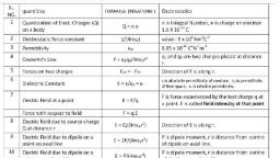
3.4 Electrostatic Field : Sen, , Cnn, Q.1 Define as related with electrostatics, electric field, , oe ___ (Dec. 05), , According to coulomb’s law, a charged body placed, near a charge will experience a force., , , , Definition :, , - Electric or electrostatic field is defined as the region, around a charged body where another charged body, experiences a mechanical force., , 3.4.1. Electrostatic Flux Lines :, , Definition :, , - The electric or electrostatic lines of force are imaginary, lines which represent the stress distribution in electric, field surrounding the charged body., , - Similar to a magnetic line of force, an electric line of, force can be defined as a line along which a free, positive charge would travel if the charge is placed in, , an electric field., , irection of resultant force :, , The direction of force experienced by this free positive, charge is given by the tangent drawn at a given point,, on the line., , be of force :, , A bunch containing a fixed number of electric lines of, force is sometimes called as a tube of force., , .2 Mapping of Electric Field :, , , , , , , , (a-506)(d) Electric field patterns, Fig. 3.4.1 : Mapping of electric field, , - The flow of electric lines of forces can be mapped by, sprinkling gypsum crystal on a glass plate placed over, the charged’ body. Some of the typical electric field, patterns are shown in Fig. 3.4.1., , 3.5 Electric Flux : Same CTRCL ALY Tre, University Questions, , Q.1 Define as related with electrostatics, electric flux., , , , (Dec. 05, Dec. 07), , Definition :, , - Electric flux (w) is defined as the number of lines of, force in any particular electric field. Electric flux is, measured in Coulomb (C)., , One coulomb :, , - One coulomb of electric flux is defined as the flux that, emanates from a positive charge of one coulomb., , Electric flux y = QCoulombs (numerically), , 3.6 Electric Flux Density (D) :, , PPU i Dec,, , , , CTBT), , , , , , PET etd i, , Q.1 Define as related with electrostatics, Electric flux, , , , , , density. (Dec. 05, Dec. 07, Dec. 08, May 11, , Definition and units :, , - The electric flux density is defined as the flux per unit, area measured at right angles to the direction of flux. It, is denoted by symbol D and measured in Coulomb per, , square metre (C/m’)., , W 4 22°. e (3.6.1), D= a c/m = since Q=y, , The electric flux density is also called as displacement, , density., , Scanned with CamScanner
Page 2 :
Piuxnuts Gicis Bisanniind Field, 3.7. Electric Field Stren NT, Intensity : Spe :May, , CIO, , . stric field, Q.1 Define as related to electrostatics, elect, , (May 06, Dec. 07), strength, , Definition and units :, , The electric field strength or field intensity at any point, in an electric field is defined as the mechanical force, experienced by a unit positive charge (charge of, 1-coulomb) when it is placed at that point in the, electric field, , The electric field strength is denoted by E and it is, Newton per Coulomb (N/C) or, , volt / metre. Its direction is same as the direction along, , measured — in, , which the force acts., , . E = F/Q Newton/Coulomb. (3.7.1), , The electric field strength increases with increase in the, value of force F., , If a charge of strength Q is placed at any point in an, electric field of intensity E, then the force experienced, by it is given by,, , F = ExQ (3.7.2), 3.7.1 Relation between Flux Density (D) and, , Electric Field Intensity (E) :, The flux density at any point is proportional to the, intensity of electric field at that point., Dee, D=kE, , Where k is the constant of proportionality., , (3.7.3), (3.7.4), , It can be shown that k is equal to the absolute, permittivity «., , D=, , cE +(3.7.4(a)), But € = €€,, , D = €¢,E (3.7.5), , ~ This is the relation between flux density (D) and electric, , field intensity (E)., , 3.8 Permittivity (e):, , , , 12, , -1 Define as related with electrostatics, permittivity., , (Der O08 Maun min na oe, , Refer to Equatiols orton, , That means the electric flux density (D) is , ne, electric field strength (E). My,, For a given value of the field strength, the, , electric flux density (D) is dependent OM the ‘, “e" which is a constant representing the ’, properties of the medium. ¢ is called as the A,, , of the medium., Definition of permittivity :, , - The permittivity is defined as the ease With, dielectric material acting as a medium, aly, electric flux to be established in it. It is den,, , representing the ., , which is a constant,, , properties of the medium., , 3.8.1 Absolute Permittivity (€) :, , EI, , , , University Questions, , Q.1 Define as related to electrostatic field,, , , , ermittivity. (t, , , , Definition and units :, , - We can define the absolute permittivity (€) as, of electric flux density to the electric field stren, is denoted by ¢ and its units are Farads/metre, , D, ’. Absolute permittivity e = Fim, , 3.8.2 Permittivity of Free Space (€,):, , Definition and units :, , The permittivity of free space is defined as tt, electric flux density in air or vacuum (or free, the corresponding electric field strength., , It is also called as electric space constant. It i, by €9 and measured in Farads / metres., , €o = ‘¢ F/min vacuum or free space, , The value of €, has been obtained experimen, , “0 = 36n% 10° F/m or, , 8.854 x 10°? Eym, , °, ", , , , Thus the valia nf ~ ts sec, Scanned with CamScanner
Page 3 :
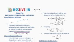
58.3 Relative Permittivity (¢,) :, , Can, , , , , , relative, , , , ‘a1 De’ as related to elec! atic field., | _ permittivity (Dec. 07), Definition and units :, , This is similar to the relative permeability (11), , The relative permittivity is defined as the ratio of, electric flux density (D) in a dielectric medium, produced in vacuum or free space, by, , to that, the same electric, field strength (E) with al! other conditions identical, , It is denoted by <, and has no units., , D, Relative permittivity, «, = D, 3.8.4), , Where D = Electric flux density produced, in a particular material, and Do = Electric flux density produced, in vacuum or free space., ~ Substituting D = € E and Dy = €9 E into Equation (3.8.4), to get., , cE, , €& =o, €oE, , Er, , “ € = €9€, F/m (3.8.5), , - From this expression, we can define the relative, permittivity (€,) as the ratio of the absolute permittivity, (e) and permittivity of free space or vacuum (€,)., , - The value of relative permittivity €, for air is assumed to, be unity i.e. 1, but its actual value is 1.0006., , - Relative permittivity is also called as dielectric, constant., , Difference between ¢ and e,:, , - The difference between ¢ and e, is that absolute, permittivity is the ratio of D and E and has units of F/m., But the relative permittivity ¢, is the ratio of D and D,, and has no units. The values of ¢, will be different for, different materials., , Higher the value of relative permittivity, easier is the, Passage of electric pulse lines through the material., , 3.9 Electric Potential (Absolute, Potential) :, , , , Let a positive charge Q is placed at a point. It is, generating its own electric field around it. Refer, , , , Fig, 3.9.1., , , , Electric potental at P is the work done, in moving the unit positive charge from, , D to point P against the electric field, , ~ of Unit positive, @ Coutomd ‘S) © ahaige, , +—— P distance ——* _ Direction of, advance, (A-510) Fig. 3.9.1, Now let a unit positive charge (of 1 Coulomb) is, brought from infinity into the field of Q. There will be a, force of repulsion between these two like charges., In order to overcome this force of repulsion, certain, amount of work should be done. Due to this work, done, the unit charge acquires a potential energy when, it reaches closer to the charge Q., , Definition :, , The electric potential at a point P is defined as the work, done in bringing the unit positive charge from infinity, to point P against the electric field. Potential is a scalar, quantity., , Electric potential = Work done, , Units of electric potential :, , The electric potential is denoted by V and measured in, joules per coulomb or volts., , 3.10 Capacitor or Condenser :, , Construction :, , Capacitor is an electronic component which is capable, of storing charge., , All capacitors consist of two parallel conducting plates, separated by an insulating material called dielectric., , Leads, for connection are brought out from the two, conducting plates as shown in Fig. 3,10.1(a)., , The ability of a capacitor to store charge is called as, capacitance., , [*—— Lead for connection, , >= Conducting plates, , , , Dielectric, material, , [*—— Lead for connection, , , , (a) Construction of a basic capacitor, , (8-516) Fin. 3.10.1 (Canta \, Scanned with CamScanner
Page 4 :
3.10.1 Types and Symbol :, , 3.10.2 Capacitor and Capacitance :, , Variable capacitor, , Fixed capacitor, , (b) Symbols, (A-516) Fig. 3.10.1, , The capacitors can be broadly classified into two, categories :, , 1. Fixed capacitors 2. Variable capacitors, , The capacitance of a fixed capacitor remains constant, whereas that of a variable capacitor will be adjustable., Fig. 3.10.1(b) shows the symbols of fixed and variable, capacitances,, , Sa RO SORE Ah, , , , , , , , University Questions, , Q.1, , Define as related to electrostatics, capacitance., (Dec. 08, May 11), , , , , , Definition of capacitance and its units :, , connections for, , A capacitor (or condenser) is formed if two conducting, surfaces or plates are separated by an insulating, medium called dielectric., , The simplified construction of a capacitor is shown in, Fig. 3.10.2(a)., , The materials used as a dielectric medium are mica,, glass, paraffin paper, polysterene, oil etc,, , Sometimes air is used as dielectric between the plates,, (Such capacitors are called as air dielectric capacitors)., , The capacitance is defined as the property of a, capacitor to store electric energy in the form of static, charge., , It is also defined as the amount of charge required to, produce a unit potential difference between the plates, of a capacitor. The unit of capacitance is Farads., , Two conducting plates, a, , External L A, , , , Dielectric, , , , the user B, ‘o—_—___], , , , (a) Construction of a capacitor, , >, , — ] Airacts as, _ dielectric, B, , , , (b) Capacitor with air acting as dielecty., (A-517) Fig. 3.10.2, , 3.10.3 Relation between Charge ang A,, Voltage :, , - The charge on a capacitor is Proportion, externally applied voltage (V) across it., , Qkx Vv e, , or Q= WV s, , - Where C = Constant of proportionality ang &, , the capacitance., , Capacitance C =, , , , 3.10.4 Definition of 1-Farad :, , - One Farad capacitance is defined as the Capa,, which needs a charge of 1-coulomb to Obs, potential difference of 1-volt across its plates,, , - For all practical purposes the farad is too large;, hence capacitance is expressed in microfars;, nanofarad (nF) or picofarad (pF), where,, , 1pF = 10° F,1nF=10°°Fand1 pF = 10°, , 3.11 Capacitance of a Parallel Plate, Capacitor :, , [University:Questions|, , Q.1 Discuss the factors which effect the capacitance, , , , , , , , , , , , (Dec.é, , ~ Let a parallel plate capacitor be fully charged t, , voltage V. Let the area of each plate (A and B) bee:, , to “A” m’ and let the separation between thet, equal to “d" metres., , ~ The relative permittivity of the dielectric used betit, , the plates be e,., , Dielectric of, , pammittivity €, \\, |, , B, , Area of each,, plate is Am, , , , , , (A-521) Fig. 3.11.1: A charged capacitor, Scanned with CamScanner
Page 5 :
Derivation :, , Let the charge stored by plate A be “Q” coulomb, This, will force an electric flux y through the dielectric, medium between the plates., , Ly, , >KE A, , ; Q, The electric flux density D = A (3.11.1), , Vv, And the electric field intensity E = qvolts /m_ ...(3.11.2), , The relation between E and D is given by,, , D = cE »(3.11.3), - Substituting the expressions of E and D we get,, Q v, AD 8G] »(3.11.4), - Rearranging we get,, Q A, v= &¢ .(3.11.5), , But we have already defined Q / V = C the capacitance., QeaA, , va fd, Substitute « = Ege, to get,, , €9E,A, , d, , , , Farad (3.11.6), , Factors affecting the value of C :, , Equation (3.11.6) tells us that the capacitance C is, directly proportional to the area of the plates and, relative permittivity ¢, of the dielectric material and it is, inversely proportional to the distance d between the, , capacitor plates., , Ex. 3.11.1: The plate area of a parallel-plate capacitor is, 0.01-sq.m. The distance between the plates is 2.5 cm. The, insulating medium is air. Find its capacitance. What would be, its capacitance, if the space between the plates is filled with, an insulating material of relative permittivity 5 ?, , May.04)'4iMarks, , Soin. :, , Given : A = 0.01 m’, d = 2.5 cm = 25 x 10°’ m, dielectric is, , air., eo€,A EA, 1. Capacitance C = =a = since ¢, = 1 for air, 8.854 x 10x 0.01, C= 95 x10", , 3.5416 x 10° F, , .Ans., , ", , , , , , 2. Now the space is filled with a material of «, = 5, , C= e,xC, , New value of C, = 5» 3.5416 pF =, , Ex. 3.11.2: A capacitor consist of two parallel rectangular, plates each 120 mm square separated by 1 mm in air. When, a voltage of 1000 V is applied between the plates an average, current of 12 mA flows for 5 second. Calculate : 1. the charge on, the capacitor, 2, the electric flux density and 3. the electric field, , COS, , , , strength in the dielectric., Soin. :, , Given: Area A =120mm’,d=1mm,, , V = 1000 Volts ,1= 12 mA, t= 5 sec., Tofind: 1.Q 2.D 3.E, , 1. ChargeQ:, , c For aire, = 1, €9 = 8.85410”, , A, ErEoq, , 120 x 10°°, 110°, , -12, %, , 8.854 x 10, , 1.06248 x 10°? F = 1.06248 pF, CV = 1.06248 x 10°” x 1000, , = 1.06248 x 10 ° coulomb., , Electric flux density (D) :, , Q_ 1.06248 x 10°, A~ 120x10°, , 2., , 8.854 x 10 * coulomb/m* Ans., , ", , 3. Electric field strength (E) :, , _ —2, ~ Anege,, 4nx 8.854 x 10 “x1x (1x10), , 9.55 x 10° N/m? ww Ans., , 3.12 Dielectric Strength :, , , , , , Dec: 08\Dec-09) May 44, |, Q.1 Define as related to electrostatics, dielectric |, , strength. (May 06, Dec. 08, May 11) |, Q.2 Explain what do you understand by dielectric, strength ? (Dec. 06, May 08, Dec. 09), , , , , , 3.5416 pF, , Scanned with CamScanner
 Learn better on this topic