Notes of FE Degree-Physics, Engineering Physics-I Interference in thin film - Study Material
Page 2 :
/, , Et1ginee11• •~ . .. , -, , 4-2, , .-,, , I, , Interference in Thin Film, ., ray AB of monochr, . ., omatic light of wavelength A, consider a, from an extended source mc1dent at B, on, pper surface of a parallel sided th' fil, ,, m m of thickn, Jie u, ess t and refractive index µ as shown in, l1, t, fig- 4..., e angle of incidence be i., , Let th, B the beam is partly reflected along BR1 and art}, ', Y refracted at an angler along BC., P, At ,, again partly reflected along CD an d part1Yrefracted along CT . Similar partial reflections and, ., , At C, 1·tis, 1, refractions occur at points D, E , etc., Thus we get a set of parallel reflected rays BR1, DR2, etc. and a set of parallel transmitted rays CT 1,, , ET2, etc., For a thin film, the waves travelling along BR1 and DR2 in the reflected system will overlap., _ These waves originate from the same incident wave AB and are hence coherent., _ Hence they will interfere constructively or destructively according to if the path difference between, them is an integral multiple of A or an odd multiple of, , ½,, , Reflected system, , air, , t, µ, , • I terference In thin films, fig. 4.1.1 . n, , DM erpendicular to BR1 . The paths travelled, ., ., P, BR and DR2, draw, tical path difference (optical path difference is, h, i,, To find the path difference between, ., al Hence t e op, by the beams beyond DM are equ . .]~a-. nee by its refractive index) between them is, . al path (llli.ere, h BCD 1•n film- Path BM in air, obtained by multiplying geometnc, ~ == Pat, == µ (BC + CD) - BM, , --------- -----, , •, •, , Ttdllaewlffte, Put li c i tlo ns
Page 5 :
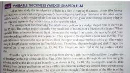
~-, , 4-5, , Engineering Physics - I (MU - FE), , =✓1 -, , cos r, , 4.2, , 8 X 5890 X 10-s, = 2 X 1.46 X 0.9395, , t, , nA, = 2µ • cos r, , t, , = 1.7176 x 10- 4 cm., , /, , ,,, ,, , Thin and Thick Films, ,, , 'Q,, , = 0.9395, , sin 2 r, , Why does an excessively thin film app~ar, t0_be, , ., , J,, , /.4., , /, , ,,,, , ~, , ·?, , perf~otlyt'fl{)Jlf when;fllu,fflf_of11e, , The effective path difference between the interfering rays in reflected light is, )., , 2 µ t cos r + 2, (i), , If the film is excessively thin, then its thickness being very small as compared to the wavelength of, , light, the term 2 µ t cos r can be neglected as compared to, becomes, , ½ which is the conditi~n for, , ½., , Hence the effective path difference, , minima. Hence every wavelength in the incident light will be, , absent in reflected system, and the film will appear black in reflected light., (ii) If the thickness of the film is large enough as compared to the wavelength of light, the path difference, at any point of the film will be large. Under these conditions the same point will be a maximum for a, large number of wavelengths, and the same point will be a minimum for another set of large number of, wavelengths. The number of wavelengths sending maximum intensity at a point are almost equal to the, number of wavelengths sending minimum intensity. Also, these wavelengths sending maximum and, minimum intensity will be distributed equally over all colours in white light. Hence the resultant, , effect at any point will be the sum of all colours i.e. white in thick film., (iii), , Hence we define 'thin film' as the film whose thickness is of the order of wavelength of the light which is, used to expose it., , 4.3, , Production of Colours in Thin Films, , ■ 111t•■•MMf-li'16'1il• 1 14Mti•Mfld, ,., (Dec. 12, Dec. 16, 3 Marfcs), ,:,/ /, ., , (May 15, 3 Marks), , -~;,/,;, , Q., , film)ii' ~~nlight.- ·, , Martes), When a thin film is exposed to white light from an extended source, it shows beautiful colours in th e, reflected system., '-'"'-~~ = ~-=--:, , •, , (May 17, 3, , Light is reflected from the top and bottom surfaces of a thin film, and the reflected rays interfere., The path difference between the interfering rays depends on the thickness of the film and the angle of, refraction r and hence on the inclination of the incident ray.
Page 7 :
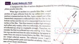
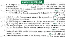
•, , 4.5, , Interf erenc e in Thin ~, , 4-7, , Engineering Physics - I (MU - FE), , Film ), Film of Non-uniform Thic knes s (Wedge-shaped, 1$1•■ -M◄ HltMGl•i§M?-W•@◄ iMMiq, ~, 1.-■ 13, 3 ~, .41,....,.,.u:;,u.,. ,,......,,, "'"" ,, ck In re11e>v, bl, a, rs, appea, film, thin, sively, exten, an, why, in, Expla, ved in reflectad light_, a due to interference in a weoge-,shaped Fdm obser, --,, , Q., Q., , Obtain the conditions for maxima and minim, , (llay 14,4Martra), Q., , Q., , a., , il, Derive the conditions of maxima and minima for int~, Why are the fringes In wedge-shaped film straight?, ), Marta, 7, ,, (Decc. 15,, wedge-shaped fflms?, (Dec. 17, 3 -... ,, fifm ls Uluminated with white fight?, What will be the fringe pattern if wedge -shaped a,r, 18,. 3 ~, to test optical fla1ness of given gtass plate. (May, Explain how interference in wedge-shaped film Is used, , OX', in Fig. 4.5.1. It is boun d by two surfa ces OX and, Consider a film of non-uniform thickness as shown, ally incre ases from O to :X., inclined at an angle 8. The thickness of the film gradu, the, as wedg e-sh aped film. The poin t O at which, Such a film of non-uniform thickness is known, thickness is zero is known as the edge of the wedge., n as the angle of wedge. Letµ be the refractive, The angle 8 between the surfaces OX and OX' is know, index of the mate rial of the film., of, h A be incid ent at an angle i on the uppe r surface, Let a beam AB of monochromatic light of wavelengt, d along BC. At C also the beam suffe rs partial, the film . It is reflected along BR1 and is trans mitte, D~ in the refle cted syste m., reflection, and refraction and finally we have the ray, at the uppe r and lowe r surfa ces of the film, we have, Thus as a resul t of parti al reflection and refraction, m., two coherent rays BR1 and D~ in the reflected syste, , x', A, , -. _ r+B, Q, , · -0., , ·: p, Fig. 4.5.1 : Interf erenc e In Wedge-ahaped fllm, , •rab elll#, •, , Pu1H 1 cat 1on S
Page 9 :
Interference in Thin Film, , 4-9, , y_ Engineering Physics - I (MU - FE), , ~, , ...., ~"!!!i, , !:: occurs for the ray BR1. Hence the total Path, h, Of, 2, Due to reflection at B, an additional path c ange, ').., , 8, difference between the interfering rays is 2 µt cos (r + ) + 2 ·, Hence for maxima, we have the condition for constructiv e interferenc e, "A, 2 µt cos (r + 0) + 2 = n"A, "A, 2 µt cos (r + 0) = (2n - 1) 2, , or, , ... (4.5.3), , n = 1, 2, 3, 4 ....., , For minima, we have the condition for destructive interferenc e, "A, "A, 2 µt cos (r + 0) + 2 = (2n - 1) 2, ... (4.5.4), , 2 µt cos (r + 0) = n"A, n = 0, 1, 2, 3, .... ., , It is clear that for a maximum or a minimum of a particular order, t must remain constant. In case of, , the wedge-shaped film, t remains constant along lines parallel to the thin edge of the wedge., Hence the maxima and minima are straight lines parallel to the thin edge of the wedge., At the thin edge, t = 0 hence path difference between the rays is, , ½, a condition for darkness. Hence the, , edge of the film appears dark. It is called as zero order hand. That is the reason an extensively thin, film appears dark (black) in reflected light., Beyond the edge for a thickness t for which path difference is A, we obtain the first bright band. Ast, 3, increases to a value for which path difference is 2A, we obtain the first dark band., Thus as the thickness increases we obtain alternate bright and dark bands which are equally spaced, and equal in width., (i) For normal incidence and air film, r, , = 0 and µ = 1, , A, Total path difference = 2t • cos 0 + 2, , 2t cos, and, (ii), , e, , A, , = (2n - 1) 2 ', , 2t cos 0 = nA, , For maxiill 8, For miniill8, , For very small angle of the wedge,, As, , e ➔ o, cos e ➔ 1, , :. For constructive interference, , ', A, 2t = (2n - 1) 2, WTldlb•-'~, V P u b lH at l fl
Page 11 :
y, , - - .. • '11111, , l"titn, , z.._, , Engineering Physics - I (MU • FE)., , 1+-- -- X n+1---- -r.~, Fig. 4.6.1, , ., Let (n + l) th maximum be obtained at a distanc, e, , Xn + 1, , f, , rom, , the thin edge Then we have,, ·, A, , 2 Xn + 1 sine = [ 2 (n + 1) - 11 . 2, or, , }, , .A, , 2 Xn + 1 • sine = (2n + 1), 2, , Therefo re from equatio ns (4.6.3) and (4.6.4) we have,, , ·,/, >--., , /., , 2 (Xn + 1 - Xn) • sin 0 = 11., ''-::?, 'l"M, Therefo re the spacing between two consecu tive bright bands is,, , P, , ... (4.6.4), , -, , / ' Y\., , A, , =Xn+ 1-Xn= -2·, 0, Sin, , sin 0 ~ 0 if 0 is small and measur ed in radians ., , Bis called fringe width., , A, ~ = 20, , For a medium of refracti ve index µ, we have, , ~=, , ~ ., 2, , asµ, "A and 0 are constan t, one can say that fringe width in wedge- shaped film is constan, t. Or wedgeshaped fringes are of consta nt thickn ess., , Ex. 4:~J; ,, , 2 . The fringe spacing is 1, , mm artd·tntr, , •M•M-1-, , Soln.:, , Given: µ, , =1.52, 11. = 5893 x 10- 8 cm,, , r~ = 1 mm= 0.1 cm., , Formu la : The fringe spacing is, , l, , ~ = 2µ0, The angle of wedge in radians is, 8, , A, , 5893 x 10- s, , = 2µ. 13 = 2 x 1.52 x O.l radians, , 5893 X lQ- S, 180, O = 2 x 1.52 x 0.1 x 7 x 3600 seconds, 8 = 40 second s of an arc., .AJlS•, ---- ---- ---- ---- -=- --=, ~~~~~~~~=---- --- --•..- T-edl~•~'.:•, ~, Publlfl r 10 "
Page 14 :
The fac tor, , A, , 2 accou nts for a p, , Now for the Air film, , h, , of n on refl ection at the lower surface of the film., h, aRe c ange, , ,1 = l, , For norma l incidNtre r = 0, For 8 Jen~ of largf' radius of curvature, 0 = O practically. This is the r eason why we prefer lens with, large radiu s., A, .-. Path difference between rays 1 and 2 is 2t + 2, At the point of contact. of t he lens and the plate, t = 0., , Path difference =, , A, , 2, , This is t he condi tion for minimum intensity. Hence the central spot is dark., For the n th maximum , we have, A, 2t + 2 = nA, , Thus a maximum of particular order n will occur for a constant value of t. In the air film, t remains, constant along a circle and hence the maximum is in the form of a circle., Different maxima will occur for different values of 't'. Similarly, it can be shown that the minima are, also circular in form., ).. , 3).. , S).., . ., The mm1ma, occur fior path diffierence 2, 2 2, , ., occur fior path difference A, V.., 3.A., ... ,, , ... and maxima, , the maxima and minima occur alternately., Each fringe is a locus of constant film thickness and hence these are fringes of constant thickness., Diameter of dark and bright rings, , Let POQ be a planoconvex lens placed on a plane glass plate AB. Let R be the radius of curvature of the, lens surface in contact with the plate. Refer Fig. 4.7.2., C, , Fig. 4.7.2, , -.\,, hGK...11111', •, , Publ lc.-t l Ons
 Learn better on this topic