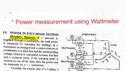
Page 1 :
3.5 Basic Principle of Wattmeter :, , We have proved that for a balanced start or delta type, , load, the total active power is given by,, P, = V3 Vilcos} BL), , — Where dis the angle measured between V, and I,., , - Equation (3.1) indicates that the power is dependent on, the power factor cos $ along with voltage and current., , - So inorder to measure the three phase active power we, need to use an instrument which will sense voltage,, current as well as the power factor and give the reading, directly in watts., , — The instrument which can do this is a wattmeter., Basics about a Wattmeter :, , — The wattmeter is an instrument which can measure the, power in single or three phase ac circuits. It gives its, reading directly in watts., , - The wattmeter has two different coils namely voltage, coil and current coil. The voltage coil is also called as, pressure coil., , , , , , , , , , , , Wattmeter, (Maine)°—}~008\—| L Current coil, c (Load), ° AAW ©\V Voltage coil, (Common) (Voltage), , Fig. 3.7 : Two coils of a wattmeter, Current coil :, - The coil shown between the terminals M (mains) and L, (load) in Fig. 3.7 is the current coil., - _ Itis to be connected in series with the load., , — The resistance of this coil is small due to its large cross, sectional area and small number of turns., , Voltage coil or pressure coil :, , - The coil shown between the terminals C (common) and, , V (voltage) in Fig. 3.7 is called as the voltage or pressure, coil., , - It is always connected across the supply to measure the, voltage., , — The resistance of voltage coil is large. It is made of thin, wire with a large number of turns., , , , eT ee ee, , Scanned with CamScanner
Page 2 :
Wattmeter reading :, — Let the current flowing through the current coil be |,, and let the voltage across the pressure coil be Vpc, — Then the wattmeter reading is given by,, W = Voce x I, x COS (Voce “Id, —”, | L__-» Angle between Vp, and I,, Current through the current coil, , Voltage across the pressure coil, Wattmeter reading ., ..(3.2), , — The wattmeter reading is proportional to the cosine of, the angle between V,, and I.. i.e. cos (pe I,)., , Scanned with CamScanner
Page 3 :
3.5.1 Power Measurement using Two, Wattmeter Method :, , TURP AENREM CEM mee, May 15, Dec. 15, Dec: 17, May 18, May 19, Y University Questions : ae, 1 Explain measurement of three al power using, = two wattmeter method., , , , , , (Dec. 42, May 14,6 6 Marks), , Q.2. Draw the circuit for measurement of 3-phase power, __ using two wattmeters and state its advantages over, , . other methods of 3-phase power measurement., a (May 13, ‘4 Marks), , In a three. ee power measure nent by two, wattmeter method, both ‘the wattmeters read the, same value. What is the power factor of the load 2, s _ Justify your answer. (Dec. 13, 4 Marks), Q.4 With the help of a neat circuit diagram and phasor, oo. diagram. explain the 2-wattmeter method | to, measure power in. a Sphese ‘balanced delta., connected load. (Dec. 14, 6 Marks), Q.5 With the help of a neat cireit diagram and. phasor, diagram explain the 2-wattmeter method. to., ‘measure power in a 3o balanced star connecte, load. (May 15, 6 Marks), 6. Explain the measurement of 36 power by tw, > wattmeter. method. (Dec. 15, 4 Marks) |, a With necessary: diagrams, prove that three phase, power. can be measured by only two watt meters. :, , A Also” prove that reactive power can be measured :, from the watimeter readi ngs. :, , oF (Dec. 47, May 19, 10 Maske, , O.8 Prove that the power in a balanced three phase, , delta connected circuit can be deduced from the, , ~-teadings of two wattmeter. Draw relevant, , connections and vector diagrams. Draw a table to, show the effect of power factor on wattmeter., , (May 18,8 Marks), Scanned with CamScanner
Page 4 :
a, The two wattmeter method is a special methog 4, , connection to measure the power in three phase a, with the use of only two wattmeters instead of the thre, ecial connection is shown in the Fig, 3g, has a current coil (CC) to be connecteg, (PC) to be connected jp, , phases. the sp!, Each wattmeter, in series and 4 potential coil, parallel., t coil of the first wattmeter is connected j, f the other wattmeter j, , e. The potential coils are, , The curren, red phase while that 0, , connected in the yellow phas, connected between the red - yellow phase ang, , yellow - blue phase as shown in Fig. 3.8., , , , , , , , Fig. 3.8, , cc = Current Coil, , PC = Poiential Coil, , Advantage :, , The two wattmeter method is a special method of, connection to measure the power in three phase system, with the use of only two wattmeters instead of the three, , , , phases., , , , = The special connection is shown in the Fig. 3, , , , Fig. 3.9, , Based on the connections in Fig 3.8, we have, , , , Scanned with CamScanner
Page 5 :
From phasor diagram shown in Fig. 3.9,, W, = Vpp Ip cos (30 - 4), W, = Vyg ly cos (30 + 9), , For a balanced load system,, , W, = V,I,cos (30-4), W, = V,I, cos (30 + 4), Now, W, + W, = V,I[cos (30 -— ) + cos (30 + 9)], , = V,1, [cos 30 cos o + Si sin o + cos 30 cos >—sin 30-sif 9], , 3, , = V/I, [2 cos 30 cos 4] = VIX 2x5 cos >, = 4/3 V,I,cos=P, , Scanned with CamScanner