Page 1 :
ELECTRONICS MECHANIC, NSQF LEVEL - 5, , 1st Year (Volume I of II), TRADE THEORY, SECTOR: ELECTRONICS & HARDWARE, , DIRECTORATE GENERAL OF TRAINING, MINISTRY OF SKILL DEVELOPMENT & ENTREPRENEURSHIP, GOVERNMENT OF INDIA, , NATIONAL INSTRUCTIONAL, MEDIA INSTITUTE, CHENNAI, Post Box No. 3142, CTI Campus,, (i) Guindy, Chennai - 600 032, , Copyright Free, Under CC BY Licence
Page 2 : Sector, , : Electronics and Hardware, , Duration : 2 - Years, Trade, , : Electronics Mechanic 1st Year (Volume I of II) - Trade Theory - NSQF level 5, , Developed & Published by, , National Instructional Media Institute, Post Box No.3142, Guindy, Chennai - 32, INDIA, Email:
[email protected], Website: www.nimi.gov.in, Printed by, National Instructional Media Institute, Chennai - 600 032, , First Edition, Second Edition, , :August 2018, :May 2019, , Copies :1,000, Copies :1,000, , Rs.235/-, , (ii), , Copyright Free, Under CC BY Licence
Page 3 :
FOREWORD, The Government of India has set an ambitious target of imparting skills to 30 crores people, one out of every, four Indians, by 2020 to help them secure jobs as part of the National Skills Development Policy. Industrial, Training Institutes (ITIs) play a vital role in this process especially in terms of providing skilled manpower., Keeping this in mind, and for providing the current industry relevant skill training to Trainees, ITI syllabus, has been recently updated with the help of Mentor Councils comprising various stakeholders viz. Industries,, Entrepreneurs, Academicians and representatives from ITIs., The National Instructional Media Institute (NIMI), Chennai, an autonomous body under the Directorate, General of Training (DGT), Ministry of Skill Development & Entrepreneurship is entrusted with developing, producing and disseminating Instructional Media Packages (IMPs) required for ITIs and other related, institutions., The institute has now come up with instructional material to suit the revised curriculum for Electronics, Mechanic Trade Theory 1st Year (Volume I of II) NSQF Level-5 in Electronics and Hardware Sector, under annual pattern. The NSQF Level - 5 Trade Theory will help the trainees to get an international equivalency, standard where their skill proficiency and competency will be duly recognized across the globe and this will, also increase the scope of recognition of prior learning. NSQF Level - 5 trainees will also get the opportunities, to promote life long learning and skill development. I have no doubt that with NSQF Level - 5 the trainers, and trainees of ITIs and all stakeholders will derive maximum benefits from these IMPs and that NIMI's effort, will go a long way in improving the quality of Vocational training in the country., The Executive Director & Staff of NIMI and members of Media Development Committee deserve appreciation, for their contribution in bringing out this publication., Jai Hind, , RAJESH AGGARWAL, Director General/Addl.Secretary, Ministry of Skill Development & Entrepreneurship,, Government of India., , New Delhi - 110 001, , (iii), , Copyright Free, Under CC BY Licence
Page 4 :
PREFACE, The National Instructional Media Institute (NIMI) was established in 1986 at Chennai by then Directorate, General of Employment and Training (D.G.E & T), Ministry of Labour and Employment, (now under Directorate, General of Training, Ministry of Skill Development and Entrepreneurship) Government of India, with technical, assistance from the Govt. of the Federal Republic of Germany. The prime objective of this institute is to, develop and provide instructional materials for various trades as per the prescribed syllabi under the Craftsman, and Apprenticeship Training Schemes., The instructional materials are created keeping in mind, the main objective of Vocational Training under, NCVT/NAC in India, which is to help an individual to master skills to do a job. The instructional materials are, generated in the form of Instructional Media Packages (IMPs). An IMP consists of Theory book, Practical, book, Test and Assignment book, Instructor Guide, Audio Visual Aid (Wall charts and Transparencies) and, other support materials., The trade practical book consists of series of exercises to be completed by the trainees in the workshop., These exercises are designed to ensure that all the skills in the prescribed syllabus are covered. The trade, theory book provides related theoretical knowledge required to enable the trainee to do a job. The test and, assignments will enable the instructor to give assignments for the evaluation of the performance of a trainee., The wall charts and transparencies are unique, as they not only help the instructor to effectively present a, topic but also help him to assess the trainee's understanding. The instructor guide enables the instructor to, plan his schedule of instruction, plan the raw material requirements, day to day lessons and demonstrations., In order to perform the skills in a productive manner instructional videos are embedded in QR code of the, exercise in this instructional material so as to integrate the skill learning with the procedural practical steps, given in the exercise. The instructional videos will improve the quality of standard on practical training and, will motivate the trainees to focus and perform the skill seamlessly., IMPs also deals with the complex skills required to be developed for effective team work. Necessary care, has also been taken to include important skill areas of allied trades as prescribed in the syllabus., The availability of a complete Instructional Media Package in an institute helps both the trainer and, management to impart effective training., The IMPs are the outcome of collective efforts of the staff members of NIMI and the members of the Media, Development Committees specially drawn from Public and Private sector industries, various training institutes, under the Directorate General of Training (DGT), Government and Private ITIs., NIMI would like to take this opportunity to convey sincere thanks to the Directors of Employment & Training, of various State Governments, Training Departments of Industries both in the Public and Private sectors,, Officers of DGT and DGT field institutes, proof readers, individual media developers and coordinators, but for, whose active support NIMI would not have been able to bring out this instructional materials., , R. P. DHINGRA, EXECUTIVE DIRECTOR, , Chennai - 600 032, , (iv), , Copyright Free, Under CC BY Licence
Page 5 :
ACKNOWLEDGEMENT, National Instructional Media Institute (NIMI) sincerely acknowledges with thanks for the co-operation and, contribution extended by the following Media Developers and their sponsoring organisations to bring out this, Instructional Material (Trade Theory) for the trade of Electronics Mechanic under Electronics and Hardware, Sector for ITIs., , MEDIA DEVELOPMENT COMMITTEE MEMBERS, , Shri. C. Anand, , -, , Vocational Instructor,, Govt. ITI for Women, Puducherry., , Shri. A. Jayaraman, , -, , Training Officer (Rtd),, Govt. of India, CTI, Guindy, Chennai - 32., , Shri. R.N. Krishnasamy, , -, , Vocational Instructor (Rtd), Govt. of India (VRC), Guindy, Chennai -32., , NIMI - COORDINATORS, Shri. K.Srinivasa Rao, , _, , Joint Director,, NIMI, Chennai - 32, , Shri. S.Gopalakrishnan, , _, , Assistant Manager,, NIMI, Chennai - 32, , NIMI records its appreciation for the Data Entry, CAD, DTP operators for their excellent and devoted services in, the process of development of this Instructional Material., NIMI also acknowledges with thanks the invaluable efforts rendered by all other NIMI staff who have contributed, towards the development of this Instructional Material., NIMI is also grateful to everyone who has directly or indirectly helped in developing this Instructional Material., , (v), , Copyright Free, Under CC BY Licence
Page 6 :
INTRODUCTION, TRADE THEORY, The manual of trade theory consists of theoretical information for the course of the Electronics Mechanic Trade, NSQF Level - 5. The contents are sequenced according to the practical exercises contained in the manual on, Trade Practical. Attempt has been made to relate the theoretical aspects with the skill covered in each exercise, to the extent possible. This co-relation is maintained to help the trainees to develop the perceptional capabilities, for performing the skills., The Trade Theory NSQF Level - 5 has to be taught and learnt along with the corresponding exercise contained, in the manual on trade practical. The indicating about the corresponding practical exercise are given in every, sheet of this manual., It will be preferable to teach/learn the trade theory connected to each exercise atleast one class before, performing the related skills in the shop floor. The trade theory is to be treated as an integrated part of each, exercise., The material is not the purpose of self learning and should be considered as supplementary to class room, instruction., TRADE PRACTICAL, The trade practical NSQF Level - 5 manual is intented to be used in workshop . It consists of a series of practical, exercies to be completed by the trainees during the course of the Electronics Mechanic trade supplemented, and supported by instructions/ informations to assist in performing the exercises. These exercises are, designed to ensure that all the skills in compliance with NSQF Level - 5., The manual is divided into ten modules. The distribution of time for the practical in the ten modules are given, below., Module 1, , Basic Workshop Practice, , 75 Hrs, , Module 2, , Basic of AC and Electrical cables, , 50 Hrs, , Module 3, , Single Range Meters, , 25 Hrs, , Module 4, , Cells & Batteries, , 25 Hrs, , Module 5, , AC & DC Measuring instruments, , 50 Hrs, , Module 6, , Soldering/ De-Soldering and various switches, , 25 Hrs, , Module 7, , Active and Passive components, , 75 Hrs, , Module 8, , Power supply circuits, , 50 Hrs, , Module 9, , Computer hardware, OS, MS Office and Networking, , 125 Hrs, , Module 10, , IC Regulators, , 25 Hrs, , Project work, , 50 Hrs, Total, , 575 Hrs, , The skill training in the computer lab is planned through a series of practical exercises centred around some, practical project. However, there are few instance where the individual exercise does not form a part of project., While developing the practical manual a sincere effort was made to prepare each exercise which will be easy, to understand and carry out even by below average traninee. However the development team accept that there, if a scope for further improvement. NIMI, looks forward to the suggestions from the experienced training faculty, for improving the manual., , (vi), , Copyright Free, Under CC BY Licence
Page 7 :
CONTENTS, Lesson No., , Title of the Lesson, , Page No., , Module 1 : Basic Workshop Practice, 1.1.01, , Familiarization of the industrial training institute, , 1, , 1.1.02, , Importance of safety and Precautions to be taken in the industry/shop floor, , 2, , 1.1.03, , Personal Protective Equipment (PPE), , 5, , 1.1.04 - 1.1.05, , First Aid, , 8, , 1.1.06, , Fire extinguishers, , 14, , 1.1.07 - 1.1.09, , Basic hand tools, , 18, , 1.1.10 - 1.1.13, , Fitting and Sheet metal work, , 25, , Module 2 : Basics of AC and Electrical Cables, 1.2.14 - 1.2.21, , Electrical Terms, Conductor and Insulator, , 27, , Module 3 : Single Range Meters, 1.3.22 - 1.3.28, , Measuring Instrument Meters, , 36, , Module 4 : Cells and Batteries, 1.4.29 - 1.4.31, , Cells and Batteries, , 44, , 1.4.32 - 1.4.35, , Secondary batteries-types of charge,discharge and maintenance, , 47, , Module 5 : AC & DC Measuring Insturments, 1.5.36 - 1.5.40, , Types of measuring instruments/ equipments uses and features, , 53, , Module 6 : Soldering/ De-soldering and various switches, 1.6.41 - 1.4.46, , Soldering of wires, Switches, , 75, , Module 7 : Active and Passive Components, 1.7.47, , Active electronic components, , 84, , 1.7.48 - 1.7.50, , Passive Component- Resistors, , 86, , 1.7.51, , Ohm’s Law, , 90, , 1.7.52 - 1.7.54, , Krichhoff’s Laws, , 92, , 1.7.55, , Inductors, , 94, , 1.7.56, , Capacitors, , 100, , 1.7.57 - 1.7.60, , Circuit breakers, Magnetism & Relays, , 108, , 1.7.61, , Time constant for RC circuit, , 117, (vii), , Copyright Free, Under CC BY Licence
Page 8 :
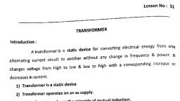
Lesson No., , Title of the Lesson, , Page No., , 1.7.62, , R.C Differentiator, , 120, , 1.7.63, , R.L.C. Series and Parallel circuit, , 122, , Module 8 : Power supply circuits, 1.8.64 - 1.8.66, , Semiconductor diodes, , 128, , 1.8.67 & 1.8.68, , Transformer, , 135, , 1.8.69 - 1.8.72, , Working principle of zener diodes, , 143, , 1.8.73, , Regulated power supply, , 150, , Module 9 : Computer hardware, OS, MS office and networking, 1.9.74 to 1.9.77, , Computer parts and their working, , 152, , 1.9.78, , CMOS setup and install the windows OS, , 161, , 1.9.79, , Switch Mode Power Supply for PC, , 163, , 1.9.80 to 1.9.83, , Hard Disk Drives, , 166, , 1.9.84, , Different types of printers, , 172, , 1.9.85, , Computer Viruses and protection, , 173, , 1.9.86, , MS office and its installation, creating basic document in MS word, , 174, , 1.9.87, , Paint tools in Windows, , 176, , 1.9.88, , MS word file, folder, editing, formatting text & labels, , 177, , 1.9.89, , MS Excel, , 179, , 1.9.90 - 1.9.92, , Microsoft Power point, Browsing & searching websites text/images, & use of E-mails, , 185, , 1.9.93 - 1.9.95, , Computer networking, Network Cable Components, and Servers, , 193, , 1.9.96, , WiFi Network, , 200, , Module 10 : IC Regulators, 1.10.97 & 1.10.98 Integrated circuit voltage regulators, , 203, , 1.10.99, , Heat sinks for IC based Regulators, , 207, , 1.10.100, , Op-Amp Voltage regulator, , 208, , 1.10.101, , IC Voltage Regulators - Variable output, , 210, , Appendix, , 212, , (viii), , Copyright Free, Under CC BY Licence
Page 9 :
LEARNING / ASSESSABLE OUTCOME, On completion of this book you shall be able to, • Perform basic workshop operations using suitable tools for fitting,, riveting,drilling etc. observing suitable care & safety., • Select and perform electrical/electronic measurement of single, range meters and calibrate the instrument., • Test & service different batteries used in electronic applications, and record the data to estimate repair cost., • Plan and execute soldering & desoldering of various electrical, components like switches, PCB & Transformers for electronic, circuits., • Test various electronic components using proper measuring, instruments and compare the data using standard parameters., • Assemble simple electronic power supply circuit and test for, functioning., • Install, configure, interconnect given computer system (S) and, demonstrate & utilize application packages for different, applications., , (ix), , Copyright Free, Under CC BY Licence
Page 10 :
SYLLABUS, Duration: Six Month, Week, No., , 1., , 2-3, , Ref. Learning, Outcome, , Professional Skills, (Trade Practical), with Indicative hours, , Professional Knowledge, (Trade Theory), , •, , Trade and Orientation, 1. Visit to various sections of the, institute and identify location, of various installations. (5 hrs), 2. Identify safety signs for danger,, warning, caution & personal, safety message. (3 hrs.), 3. Use of personal protective, equipment (PPE). (5 hrs), 4. Practice elementary first aid., (5 hrs), 5. Preventive measures for, electrical accidents & steps to, be taken in such accidents.(2 hrs), 6. Use of Fire extinguishers. (5 hrs), , Familiarization with the working, of Industrial Training Institute, system., Importance of safety and, precautions to be taken in the, industry/shop floor., Introduction to PPEs., Introduction to First Aid., Response to emergencies e.g., power failure, fire, and system, failure., Importance of housekeeping &, good shop floor practices., Occupational Safety & Health:, Health, Safety and Environment, guidelines, legislations &, regulations as applicable., , Hand tools and their uses, 7. Identify the different hand, tools. (5 hrs), 8. Selection of proper tools for, operation and precautions in, operation. (7 hrs), 9. Care & maintenance of trade, tools. (8 hrs), 10.Practice safety precautions, while working in fitting jobs., (10 hrs), 11. Workshop practice on filing, and hacks awing. (5 hrs), 12.Practice simple sheet metal, works, fitting and drilling. (5hrs), 13.Make an open box from metal, sheet. (10 hrs), , Identification, specifications,, uses and maintenance of, commonly used hand tools., State the correct shape of files, for filing different profiles., Riveting of tags and lugs,, cutting and bending of sheet, metals,chassis and cabinets., , Basics of AC and Electrical Cables, 14.Identify the Phase, Neutral and, Earth on power socket, use a, testers to monitor AC power., (6 hrs), 15.Construct a test lamp and use, it to check mains healthiness., (7 hrs), 16.Measure the voltage between, phase and ground and rectify, earthing. (5 hrs), 17.Identify and test different AC, mains cables. (7 hrs), 18.Prepare terminations, skin the, electrical wires /cables using, , Basic terms such as electric, charges, Potential difference,, Voltage, Current, Resistance., Basics of AC & DC. Various, terms such as +ve cycle, -ve, cycle, Frequency, Time period,, RMS, Peak, Instantaneous, value. Single phase and Three, phase supply., Terms like Line and Phase, voltage/ currents. Insulators,, conductors and semiconductor, properties. Different type of, electrical cables and their, Specifications. Types of wires &, , Apply safe working, practices, , • Perform basic, workshop operations, using suitable tools, for fitting, riveting,, drilling etc observing, suitable care & safety, , 4-5, , • Select and perform, electrical/ electronic, measurement of single, range meters and, calibrate the instrument., , (x), , Copyright Free, Under CC BY Licence
Page 11 :
6, , Select and perform, electrical/ electronic, measurement of, single range meters, and calibrate the, instrument., , 7, , Test & service, different batteries, used in electronic, applications and, record the data, to estimate, repair cost., , 8-9, , wire stripper and cutter. (7hrs), 19.Measure the gauge of the wire, using SWG and outside, micrometer. (5 hrs), 20. Refer table and find current, carrying capacity of wires., (3 hrs), 21.Crimp the lugs to wire end., (5 hrs), 22.Measure AC and DC, voltages using multi meter. (5 hrs), , cables, standard wire gauge (SWG)., Classification of cables, according to gauge (core size),, number of conductors, material,, insulation strength, flexibility etc., , 23.Identify the type of meters by dial, and scale marking/ symbols. (3 Hrs), 24.Demonstrate various analog, measuring Instruments. (3 Hrs), 25.Find the minimum and maximum, measurable range of the meter. (3, Hrs), 26.Carryout mechanical zero setting of, a meter. (5 Hrs), 27.Check the continuity of wires, meter, probes and fuse etc. (5 Hrs), 28.Measure voltage and current using, clamp meter. (6 Hrs), , Single range meters Introduction to, electrical and electronic measuring, instruments. Basic principle and, parts of simple meters., Specifications, symbols used in, dial and their meaning., , Cells & Batteries, 29.Identify the +ve and -ve terminals of, the battery. (2 hrs), 30.Identify the rated output voltage and, Ah capacity of given battery. (1 hrs), 31.Measure the voltages of the given, cells/battery using analog/ digital, multimeter. (3 hrs), 32.Charge and discharge the battery, through load resistor. (5 hrs), 33.Maintain the secondary cells. (5 hrs), 34.Measure the specific gravity of the, electrolyte using hydrometer. 3 hrs), 35.Test a battery and verify whether the, battery is ready for use of needs, recharging. (6 hrs), , Test various electronic, components, using proper, measuring, instruments and, compare the, data using standard, parameter., , AC & DC measurements, 36.Use the multi meter to, measure the various functions, (AC V, DC V, DC I, AC I, R) (8 hrs.), 37.Identify the different types of meter, for measuring AC & DC parameters, (8 hrs.), 38.Identify the different controls on the, CRO front panel and observe the, function of each control (12hrs.), 39.Measure DC voltage, AC, voltage, time period using CRO sine, wave parameters (10hrs.), 40.Identify the different controls on the, function generator front panel and, observe the function of each, controls (12 hrs.), , Cells & Batteries, Construction, types of, primary and secondary cells., Materials used, Specification, of cells and batteries. Charging, process, efficiency, lifeof cell/battery., Selection of cells / Batteries, etc. Use of Hydrometer. Types of, electrolytes used in cells and, batteries. Series/ parallel connection, of batteries and purpose of such, connections., , Introduction to electrical, measuring instruments., Importance and classification of, meters., Forces necessary to work a meter., MC and MI meters., Range extension, need of, calibration., Characteristics of meters and, errors in meters., Multi meter, use of meters in, different circuits., Care and maintenance of meters., Use of CRO, Function generator,, LCR meter, , (xi), , Copyright Free, Under CC BY Licence
Page 12 :
10, , 11-13, , Plan and execute, soldering &, desoldering of various, electrical components, like Switches, PCB, & Transformers for, electronic circuits., , Soldering/ De-soldering and Various, Switches, 41.Practice soldering on different, electronic components, small, transformer and lugs. (5 hrs), 42.Practice soldering on IC bases, and PCBs. (5 hrs), 43.Practice de-soldering using, pump and wick (2 hrs), 44.Join the broken PCB track and, test (3 hrs), 45.Identify and use SPST, SPDT,, DPST, DPDT, tumbler, push, button, toggle, piano switches, used in electronic industries (5 hrs), 46.Make a panel board using, different types of switches for, a given application (5 hrs), , Different types of soldering guns,, related to Temperature and, wattages, types of tips. Solder, materials and their grading. Use of, flux and other materials. Selection, of soldering gun for specific, requirement. Soldering and Desoldering stations and their, specifications. Different switches,, their specification and usage., , • Test various, electronic, components, using proper, measuring, instruments, and compare the, data using, standard, parameter., • Assemble simple, electronic power, supply circuit and, test for, functioning., , Active and Passive Components, 47. Identify the different types of, active electronic components., (3 hrs)., 48. Measure the resistor value by, colour code and verify the, same by measuring with, multimeter (3 hrs), 49.Identify resistors by their, appearance and check physical, defects. (2 hrs), 50.Identify the power rating of, carbon resistors by their size., (3 hrs), 51.Practice on measurement of, parameters in combinational, electrical circuit by applying, Ohm’s Law for different, resistor values and voltage, sources. (9 hrs), 52.Measurement of current and, voltage in electrical circuits to, verify Kirchhoff’s Law (5 Hrs), 53.Verify laws of series and, parallel circuits with voltage, source in different, combinations. (5 hrs), 54.Measure the resistance,, Voltage, Current through series, and parallel connected, networks using multi meter (8 hrs), 55.Identify different inductors and, measure the values using LCR, meter (5 hrs), 56.Identify the different, capacitors and measure, capacitance of various, capacitors using LCR meter (5 hrs), 57.Identify and test the circuit, breaker and other protecting, devices. (5 hrs), , Ohm’s law and Kirchhoff’s Law., Resistors; types of resistors, their, construction & specific use,, colorcoding, power rating., Equivalent Resistance of series, parallel circuits. Distribution of V & I, in series parallel circuits., Principles of induction, inductive, reactance. Types of inductors,, construction, specifications,, applications and Types of capacitors,, construction, specifications and, applications. Dielectric constant., Significance of Series parallel, connection of capacitors. Capacitor, behaviour with AC and DC. Concept, of Time constant of a RC circuit., Concept of Resonance and its, application in RC, RL & RLC series, and parallel circuit. Properties of, magnets and their materials,, preparation of artificial magnets,, significance of electro magnetism,, types of cores. Relays, types,, construction and specifications etc., energy storage concept. Self and, Mutual induction. Behaviour of, inductor at low and high frequencies., Series and parallel combination, Q, factor. Capacitance and Capacitive, Reactance, Impedance. Types of, capacitors, construction,, specifications and applications., Dielectric constant. Significance of, Series parallel connection of, capacitors. Capacitor behaviour with, AC and DC. Concept of Time, constant of a RC circuit. Concept of, Resonance and its application in RC,, RL & RLC series and parallel circuit., , (xii), , Copyright Free, Under CC BY Licence
Page 13 :
Properties of magnets and their, materials, preparation of artificial, magnets, significance of electro, magnetism, types of cores., Relays, types, construction and, specifications etc., 14-15, , Assemble simple, electronic power, supply circuit and, test for functioning., , 16-20, , Install, configure,, interconnect given, computer system(s), and demonstrate &, utilize application, packages for different, application, , Power Supply Circuits, 64.Identify different types of, diodes, diode modules and, their specifications. (5 hrs), 65.Test the given diode using, multi meter and determine, forward to reverse resistance, ratio. (5 hrs), 66.Measure the voltage and, current through, 67.Identify different types of, transformers and test. (3 hrs), 68.Identify the primary and, secondary transformer windings, and test the polarity (2 hrs), 69.Construct and test a half wave,, full wave and Bridge rectifier, circuit. (10 hrs), 70.Measure ripple voltage, ripple, frequency and ripple factor of, rectifiers for different load and, filter capacitors. (5 hrs), 71.Identify and test Zener diode., (2 hrs), 72.Construct and test Zener based, voltage regulator circuit. (5 hrs), 73.Calculate the percentage, regulation of regulated power, supply. (5 hrs), , Semiconductor materials,, components, number coding, for different electronic components, such as Diodes and Zeners etc. PN, Junction, Forward and Reverse, biasing of diodes. Interpretation of, diode specifications. Forward current, and Reverse voltage. Packing styles, of diodes. Different diodes, Rectifier, configurations, their efficiencies,, Filter components and their role in, reducing ripple. Working principles of, Zener diode, varactor diode, their, specifications and applications., Working principle of a Transformer,, construction, Specifications and, types of cores used. Step-up, Step, down and isolation transformers with, applications. Losses in Transformers., Phase angle,phase relations, active, and reactive power, power factor, and its importance., , Computer Hardware, OS, MS office and, Networking, 74.Identify various indicators, cables,, connectors and ports on the, computer cabinet. (5 hrs), 75.Demonstrate various parts of the, system unit and motherboard, components. (5 hrs), 76.Identify various computer peripherals, and connect it to the system. (5 hrs), 77.Disable certain functionality by, disconnecting the concerned cables, SATA/ PATA. (5 hrs), 78.Replace the CMOS battery and, extend a memory module. (5 hrs), 79.Test and Replace the SMPS (5 hrs), 80.Replace the given DVD and HDD on, the system (5 hrs), 81.Dismantle and assemble the, desktop computer system. (10hrs), 82.Boot the system from Different, options (5 hrs), , Basic blocks of a computer,, Components of desktop and, motherboard. Hardware and software,, I/O devices, and their working., Different types of printers, HDD,, DVD. Various ports in the computer., Windows OS MS widows:Starting, windows and its operation, file, management using explorer, Display, & sound properties, screen savers,, font management, installation of, program, setting and using of control, panel., application of accessories,, various IT tools and applications., Concept of word processing,: MS, word – Menu bar, standard tool bar,, editing, formatting, printing of, document etc. Excel – Worksheet, basics, data entry and formulae., Moving data in worksheet using tool, bars and menu bars, Formatting and, calculations, printing worksheet,, , (xiii), , Copyright Free, Under CC BY Licence
Page 14 :
21, , 22 - 23, , 24-25, , Assemble simple, electronic power, supply, circuit and test for, functioning., , 83.Install OS in a desktop computer., (5 hrs), 84.Install a Printer driver software and, test for print outs (5 hrs), 85.Install antivirus software, scan the, system and explore the options in, the antivirus software. (5 hrs), 86.Install MS office software (5 hrs), 87.Create folder and files, draw pictures, using paint. (5 hrs), 88.Explore different menu/ tool/ format/, status bars of MS word and practice, the options. (8 hrs), 89.Explore different menu/ tool/ format/, status bars of MS excel and practice, the options. (7 hrs), 90.Prepare power point presentation on, any three known topics with various, design, animation and visual effects., (5 hrs), 91.Convert the given PDF File into Word, file using suitable software. (5 hrs), 92.Browse search engines, create email, accounts, practice sending and, , creating multiple work sheets,, creating charts. Introduction to power, point Basics of preparing slides,, different design aspects of slides,, animation with slides etc. Concept of, Internet, Browsers, Websites, search, engines, email, chatting and, messenger service.Downloading the, Data and program files etc. Computer, Networking:- Network features Network medias Network topologies,, protocols- TCP/IP, UDP, FTP models, and types. Specification and, standards, types of cables, UTP,, STP, Coaxial cables. Network, components like hub, Ethernet, switch, router, NIC Cards,, connectors, media and firewall., Difference between PC & Server., , 98. Identify the different types of, fixed +ve and – ve regulator ICs, and the different current ratings, (78/79 series) (5 hrs), 99. Identify different heat sinks for, IC based regulators. (2 hrs), 100.Observe the output voltage of, different IC 723 metal/ plastic, type and IC 78540 regulators by, varying the input voltage with, fixed load (8 hrs), 101.Construct and test a 1.2V – 30V, variable output regulated power, supply using IC LM317T. (5 hrs), , Regulated Power supply, using 78XX series, 79XX, series. Op-amp regulator,, 723 regulator,, (Transistorized & IC based)., Voltage regulation, error, correction and amplification, etc., , Project work / Industrial visit Broad areas:, 1. Full wave Voltage rectifier with indicator., 2. Transformer less 12 V dual power supply, 3. Versatile regulated power supply, 4. AC/DC voltage tester., 5. Modular rectifiers., 6. Half wave dual power supply with zener diode., Revision, , (xiv), , Copyright Free, Under CC BY Licence
Page 15 :
Electronics & Hardware, Related Theory for Exercise 1.1.01, Electronics Mechanic - Basic Workshop Practice, Familiarization of the Industrial Training Institute, Objectives: At the end of this lesson you shall be able to, • identify the staff structure of the institute, • list the available trades in the institute and their functions, • describe the ITI training system in India., Industrial Training Institutes (ITI) plays a vital role in the, economic development of the country, especially in terms, of providing skilled manpower requirements by training, competent, quality craftsmen., , The head of the ITI is the Principal, under whom there is, one Vice-Principal, Group Instructor/ Training officer/, A.T.O and a number of trade instructors as shown in the, Organisation chart of ITI., , The Directorate General of Training (DGT) comes under, the Ministry of Skill Development and Entrepreneurship, (MSDE) offers a range of vocational training under, engineering and non engineering trades affiliated with the, National Council for Vocational Training (NCVT) NewDelhi., NCVT is the Govt of India body responsible for framing the, polices, approving the syllabus for Craftsman Training, System (CTS), carrying out the All India Trade Test and, issuing the National Trade Certificates (NTC) to the, successful candidates., , There are133 trades selected for vocational training and, 261 trades identified for Apprentice training, according to, the requirement of industrial needs and the duration of the, training is from 1 year to 2 years., , In India there are about 2293 Govt. ITIs and 10872 Private, ITIs. (Based on the Govt.of India, Ministry of Labour Annual, report of 2016-2017). The Govt. ITIs in each state functioning, under the Directorate of Employment and Training Dept, (DET) under the state Govts., , At present the Electronic Mechanic trade has been, included under National Skill Qualification Frame work, (NSQF) with level - 5 competency. The trainees are, advised to make a list of othe trades available in their ITI,, the type of training and the scope of these trades in getting, self employment or job opportunity in the rural and urban, areas and also identify the location of the ITI, nearby, hospital, fire station and police station ect., , 1, , Copyright Free, Under CC BY Licence
Page 16 :
Electronics & Hardware, Related Theory for Exercise 1.1.02, Electronics Mechanic - Basic Workshop Practice, Importance of safety and precautions to be taken in the industry/ shop, floor, Objectives: At the end of this lesson you shall be able to, • state the importance of safety, • state the personal safety precautions to be observed, • list out the safety precautions to be observed while working on the machines., Importance of safety, , Don’t cut practical jokes while on work., , Generally accidents do not happen; they are caused., Most accidents are avoidable. A Good craftsman, having, a knowledge of various safety precautions, can avoid, accidents to himself and to his fellow workers and protect, the equipment from any damage. To achieve this, it is, essential that every person should follow safety procedure., (Fig 1), , Use the correct tools for the job., Keep the tools at their proper place., Wipe out split oil immediately., Replace worn out or damaged tools immediately., Never direct compressed air at yourself or at your coworker., Ensure adequate light in the workshop., Clean the machine only when it is not in motion., Sweep away the metal cuttings., Know everything about the machine before you start it., Personal safety, Wear a one piece overall or boiler suit., Keep the overall buttons fastened., Don’t use ties and scarves., Roll up the sleeves tightly above the elbow., Wear safety shoes or boots or chain., Cut the hair short., Don’t wear a ring, watch or chain., Never lean on the machine., Don’t clean hands in the coolant fluid., Don’t remove guards when the machine is in motion., , Safety in a workshop can be broadly classified into 3, categories., , Don’t use cracked or chipped tools., , • General safety, , - the workpiece is securely mounted, , • Personal safety, , - the feed machinery is in the neutral, , • Machine safety, , - the work area is clear., , General safety, Keep the floor and gangways clean and clear., , Don’t adjust clamps or holdig devices while the machine, is in motion., , Move with care in the worksop, do not run., , Never touch the electrical equipment with wet hands., , Don’t leave the machine which is in motion., , Don’t use any faulty electrical equipment., , Don’t touch or handle any equipment/ machine unless, authorised to do so., , Ensure that electrical connections are made by an, authorised electrician only., , Don’t walk under suspended loads., , Concentrate on your work., , Don’s start the machine until, , 2, , Copyright Free, Under CC BY Licence
Page 17 :
Have a calm attitude., , Safety Sign Boards, , Do things in a methodical way., , Signboards are a common sight in almost all places such, as roadways, railways, hospitals, offices, instituition,, industrial units and so on., , Don’t engage yourself in conversation with others while, concentrating on your job., , Signboards are visual indicators. The signs on the, signboards may be just a symbol, a small text, a figure or, a combination of these., , Don’t distract the attention of others., Don’t try to stop a running machine with hands., Machine safety, Switch off the machine immediately if something goes, wrong., , Signboards carry a single clear message. These messages, are to ensure safety., Sigboards can be classified into four basic categories., , Keep the machine clean., , a) Prohibition signs, , Replace any worn out or damaged accessories, holding, devices, nuts, bolts, etc., as soon as possible., , Indicating a behaviour which is prohibited (not allowed) in, that situation or environment. Refer to chart 1 for examples., , Do not attempt operating the machine until you know how, to operate it properly., , b) Mandatory signs, , Do not adjust tool or the workpiece unless the power is off., , Indicating a behaviour which is a must, which when not, obeyed may cause accidents. Refer to chart 1 for examples., , Stop the machine before changing the speed., , c) Warning signs, , Disengage the automatic feeds before switching off., , Indicating a warning such tht suitable precatution is taken., Refer to chart 1 for examples., , Check the oil level before starting the machine., Never start a machine unless all the safety guards are in, position., Take measurements only after stopping the machine., , d) Information signs, Giving information which is very useful and reduces waste, of time. Refer to chart 1 for examples., , Use wooden planks over the bed while loading and, unloading heavy jobs., Safety is a concept, understand it., Safety is a habit, cultivate it., Chart 1, a) Prohibition signs, Shape, , Circular., , Colour, , Red border and crossbar., Black symbol on white, background., , Meaning, , Shows what must not be, done., , Example, , No smoking and naked, flames, , Shape, , Circular., , Colour, , White symbol on blue, background., , Meaning, , Shows what must not be, done., , Example, , Wear hand protection., , b) Mandatory signs, , E&H : Electronics Mechanic (NSQF LEVEL 5) - Related Theory for Ex 1.1.02, , Copyright Free, Under CC BY Licence, , 3
Page 18 :
c) Warning signs, , Shape, , Triangular., , Colour, , Yellow background with, black border and symbols., , Meaning, , Warns of hazard or danger., , Example, , Caution, risk of electric, shock., , Shape, , Square or oblong, , Colour, , White symbols on green, background., , Meaning, , Indicates or gives, information of safety, provision/First aid, , Example, , Caution, risk of electric, shock., , d) Information signs, , 4, , E&H : Electronic Mechanic (NSQF LEVEL 5) - Related Theory for Ex 1.1.02, , Copyright Free, Under CC BY Licence
Page 19 :
Electronics & Hardware, Related Theory for Exercise 1.1.03, Electronics Mechanic - Basic Workshop Practice, Personal Protective Equipment (PPE), Objectives: At the end of this lesson you shall be able to, • state the personal protective equipment and its purpose, • list the most common type of personal protective equipment, • list the conditions for selection of personal protective equipment., Personal protective equipment (PPE), , •, , Devices, equipments, or clothing used or worn by the, employees, as a last resort, to protect against hazards in, the workplace. The primary approach in any safety effort, is that the hazard to the workmen should be eliminated or, controlled by engineering methods rather than protecting, the workmen through the use of personal protective, equipment (PPE). Engineering methods could include, design change, substitution, ventilation, mechanical, handling, automation, etc. In situations where it is not, possible to introduce any effective engineering methods, for controlling hazards, the workman shall use appropriate, types of PPE., As changing times have modernized the workplace,, government and advocacy groups have brought more safety, standards to all sorts of work environments. The Factories, Act, 1948 and several other labour legislations 1996 have, provisions for effective use of appropriate types of PPE., Use of PPE is an important., Ways to ensure workplace safety and use personal, protective equipment (PPE) effectively., •, , •, , •, , •, , Inspection of gear thoroughly to make sure that it has, the standard of quality and adequately protect the user, should be continuously carried out., , Categories of PPEs, Depending upon the nature of hazard, the PPE is broadly, divided into the following two categories:, 1 Non-respiratory: Those used for protection against, injury from outside the body, i.e. for protecting the head,, eye, face, hand, arm, foot, leg and other body parts, 2 Respiratory: Those used for protection from harm due, to inhalation of contaminated air., They are to meet the applicable BIS (Bureau of Indian, Standards) standards for different types of PPE., The guidelines on 'Personal Protective Equipment' is issued, to facilitate the plant management in maintaining an, effective programme with respect to protection of persons, against hazards, which cannot be eliminated or controlled, by engineering methods listed in table1., Table1, , Workers to get up-to-date safety information from the, regulatory agencies that oversees workplace safety in, their specific area., , No., , Title, , PPE1, , Helmet, , To use all available text resources that may be in work, area and for applicable safety information on how to, use PPE best., , PPE2, , Safety footwear, , PPE3, , Respiratory protective, , When it comes to the most common types of personal, protective equipment, like goggles, gloves or bodysuits,, these items are much less effective if they are not worn, at all times, or whenever a specific danger exists in a, work process. Using PPE consistently will help to avoid, some common kinds of industrial accidents., Personal protective gear is not always enough to protect, workers against workplace dangers. Knowing more, about the overall context of your work activity can help, to fully protect from anything that might threaten health, and safety on the job., , equipment, PPE4, , Arms and hands protection, , PPE5, , Eyes and face protection, , PPE6, , Protective clothing and cover, all, , PPE7, , Ears protection, , PPE8, , Safety belt and harnesses, , Personal protective equipments and their uses and hazards are as follows, Types of protection, Head Protection (Fig 1), , Hazards, 1. Falling objects, 2. Striking against objects, 3. Spatter, , PPE to be used, Helmets, , 5, , Copyright Free, Under CC BY Licence
Page 20 :
6, , Foot protection (Fig 2), , 1. Hot spatter, 2. Falling objects, 3. Working wet area, , Leather leg guards, Safety shoes, Gum boots, , Nose (Fig 3), , 1. Dust particles, 2. Fumes/ gases/ vapours, , Nose mask, , Hand protecion (Fig 4), , 1. Heat burn due to direct contact, 2. Blows sparks moderate heat, 3. Electric shock, , Hand gloves, , Eye protection (Fig 5, Fig 6), , 1. Flying dust particles, 2. UV rays, IR rays heat and, High amount of visible radiation, , Goggles, Face shield, Hand shield, Head shield, , Face Protection (Fig 6, Fig 7), , 1. Spark generated during, Welding, grinding, 2. Welding spatter striking, 3. Face protection from, UV rays, , Face shield, Head shield with or, without ear muff, Helmets with welders, screen for welders, , Ear protection (Fig 7), , 1. High noise level, , Ear plug, Ear muff, , Body protection (Fig 8, Fig 9), , 1. Hot particles, , Leather aprons, , E&H : Electronics Mechanic (NSQF LEVEL 5) - Related Theory for Ex 1.1.03, , Copyright Free, Under CC BY Licence
Page 21 :
Quality of PPE’s, PPE must meet the following criteria with regard to its, quality-provide absolute and full protection against possible, hazard and PPE’s be so designed and manufactured out, of materials that it can withstand the hazards against which, it is intended to be used., Selection of PPE’s requires certain conditions, •, , Nature and severity of the hazard, , •, , Type of contaminant, its concentration and location of, contaminated area with respect to the source of, respirable air, , •, , Expected activity of workman and duration of work,, comfort of workman when using PPE, , •, , Operating characteristics and limitations of PPE, , •, , Ease of maintenance and cleaning., , •, , Conformity to Indian/ International standards and, availability of test certificate., , Proper use of PPEs, Having selected the proper type of PPE, it is essential, that the workman wears it. Often the workman avoids, using PPE. The following factors influence the solution to, this problem., •, , The extent to which the workman understands the, necessity of using PPE, , •, , The ease and comfort with which PPE can be worn, with least interference in normal work procedures, , •, , The available economic, social and disciplinary, sanctions which can be used to influence the attitude, of the workman, , •, , The best solution to this problem is to make 'wearing, of PPE' mandatory for every employee., , •, , In other places, education and supervision need to be, intensified. When a group of workmen are issued PPE, for the first time., , E&H : Electronics Mechanic (NSQF LEVEL 5) - Related Theory for Ex 1.1.03, , Copyright Free, Under CC BY Licence, , 7
Page 22 :
Electronics & Hardware, Related Theory for Exercise 1.1.04 & 1.1.05, Electronics Mechanic - Basic Workshop Practice, First Aid, Objectives: At the end of this lesson you shall be able to, • state the first aid, • explain the ABC of the first aid, • explain the first-aid treatment for a victim, • state the importance of house keeping, • explain environment, health and safety, • state the importance of safety and safety signs., First aid is defined as the immediate care and support, given to an acutely injured or ill person, primarily to save, life, prevent further deterioration or injury, plan to shift the, victim to safer place, provide best possible comfort and, finally help them to reach the medical centre/ hospital, through all available means. It is an immediate life-saving, procedure using all resources available within reach., Imparting knowledge and skill through institutional teaching, at younger age group in schools, colleges, entry point at, industry level is now given much importance. Inculcating, such habits at early age, helps to build good healthcare, habits among people., First aid procedure often consists of simple and basic life, saving techniques that an individual performs with proper, training and knowledge., The key aims of first aid can be summarized in three key, points:, •, , •, , •, , Preserve life: If the patient was breathing, a first aider, would normally then place them in the recovery position,, with the patient leant over on their side, which also has, the effect of clearing the tongue from the pharynx. It, also avoids a common cause of death inunconscious, patients, which is choking on regurgitated stomach, contents. The airway can also become blocked through, a foreign object becoming lodged in the pharynx or, larynx, commonly called choking. The first aider will, be taught to deal with this through a combination of, 'back slaps' and 'abdominal thrusts'. Once the airway, has been opened, the first aider would assess to see if, the patient is breathing., Prevent further harm: Also sometimes called prevent, the condition from worsening, or danger of further injury,, this covers both external factors, such as moving a, patient away from any cause of harm, and applying, first aid techniques to prevent worsening of the condition,, such as applying pressure to stop a bleed becoming, dangerous., Promote recovery: First aid also involves trying to, start the recovery process from the illness or injury,, and in some cases might involve completing a, treatment, such as in the case of applying a plaster to, a small wound., , Training, Basic principles, such as knowing to use an adhesive, bandage or applying direct pressure on a bleed, are often, acquired passively through life experiences. However, to, provide effective, life-saving first aid interventions requires, instruction and practical training. This is especially true, where it relates to potentially fatal illnesses and injuries,, such as those that require cardiopulmonary resuscitation, (CPR); these procedures may be invasive, and carry a, risk of further injury to the patient and the provider. As with, any training, it is more useful if it occurs before an actual, emergency, and in many countries, emergency ambulance, dispatchers may give basic first aid instructions over the, phone while the ambulance is on the way. Training is, generally provided by attending a course, typically leading, to certification. Due to regular changes in procedures and, protocols, based on updated clinical knowledge, and to, maintain skill, attendance at regular refresher courses or, re-certification is often necessary. First aid training is often, available through community organization such as the Red, cross and St. John ambulance., ABC of first aid, ABC stands for airway, breathing and circulation., •, , Airway: Attention must first be brought to the airway, to ensure it is clear. Obstruction (choking) is a lifethreatening emergency., , •, , Breathing: Breathing if stops, the victim may die soon., Hence means of providing support for breathing is an, important next steps. There are several methods, practiced in first aid., , •, , Circulation: Blood circulation is vital to keep person, alive. The first aiders now trained to go straight to chest, compressions through CPR methods., , When providing first aid one needs to follow some rule., There are certain basic norms in teaching and training, students in the approach and administration of first aid to, sick and injured., Not to get panic, Panic is one emotion that can make the situation more, worse. People often make mistake because they get panic., Panic clouds thinking may cause mistakes. First aider, need calm and collective approach. If the first aider himself, is in a state of fear and panic gross mistakes may result., , 8, , Copyright Free, Under CC BY Licence
Page 23 :
It's far easier to help the suffering, when they know what, they are doing, even if unprepared to encounter a situation., Emotional approach and response always lead to wrong, doing and may lead one to do wrong procedures. Hence, be calm and focus on the given institution. Quick and, confident approach can lessen the effect of injury., , Maintain the hygiene, , Call medical emergencies, , Always clean the wound thoroughly before applying the, bandage gently wash the wound with clean water., , If the situation demands, quickly call for medical, assistance. Prompt approach may save the life., Surroundings play vital role, Different surroundings require different approach. Hence, first aider should study the surrounding carefully. In other, words, one need to make sure that they are safe and are, not in any danger as it would be of no help that the first, aider himself get injured., Do no harm, Most often over enthusiastically practiced first aid viz., administering water when the victim is unconscious,, wiping clotted blood (which acts as plug to reduce, bleeding), correcting fractures, mishandling injured parts, etc., would leads to more complication. Patients often, die due to wrong FIRST AID methods, who may otherwise, easily survive. Do not move the injured person unless, the situation demands. It is best to make him lie wherever, he is because if the patient has back, head or neck injury,, moving him would causes more harm., This does not mean do nothing. It means to make sure, that to do something the care gives feel confident through, training would make matters safe. If the first aider is not, confident of correct handling it is better not to intervene, of doing it. Hence moving a trauma victim, especially an, unconscious one, needs very careful assessment., Removal of an embedded objects (Like a knife, nail) from, the wound may precipitate more harm (e.g. increased, bleeding). Always it is better to call for help., Reassurance, Reassure the victim by speaking encouragingly with him., Stop the bleeding, If the victim is bleeding, try to stop the bleeding by applying, pressure over the injured part., Golden hours, India have best of technology made available in hospitals, to treat devastating medical problem viz. head injury,, multiple trauma, heart attack, strokes etc, but patients, often do poorly because they don't gain access to that, technology in time. The risk of dying from these, conditions, is greatest in the first 30 minutes, often, instantly. This period is referred to as Golden period. By, the time the patient reach the hospital, they would have, passed that critical period. First aid care come handy to, save lives. It helps to get to the nearest emergency room, as quickly as possible through safe handling and, transportation. The shorter that time, the more likely the, best treatment applied., , Most important, the first aider need to wash hands and, dry before giving any first aid treatment to the patient or, wear gloves in order to prevent infection., Cleaning and dressing, , Not to use local medications on cuts or open wounds, They are more irritating to tissue than it is helpful. Simple, dry cleaning or with water and some kind of bandage are, best., CPR (Cardio-Pulmonary Resuscitation) can be lifesustaining, CPR can be life sustaining. If one is trained in PR and the, person is suffering from choking or finds difficulty in, breathing, immediately begin CPR. However, if one is not, trained in CPR, do not attempt as you can cause further, injury. But some people do it wrong. This is a difficult, procedure to do in a crowded area. Also there are many, studies to suggest that no survival advantage when, bystanders deliver breaths to victims compared to when, they only do chest compressions. Second, it is very difficult, to carry right maneuver in wrong places. But CPR, if, carefully done by highly skilled first aiders is a bridge that, keeps vital organs oxygenated until medical team arrives., Declaring death, It is not correct to declare the victim's death at the accident, site. It has to be done by qualified medical doctors., How to report an emergency?, Reporting an emergency is one of those things that seems, simple enough, until actually when put to use in emergency, situations. A sense of shock prevail at the accident sites., Large crowd gather around only with inquisitive nature,, but not to extend helping hands to the victims. This is, common in road side injuries. No passer-by would like to, get involved to assist the victims. Hence first aid, management is often very difficult to attend to the injured, persons. The first aiders need to adapt multi-task strategy, to control the crowd around, communicate, to the rescue team, call ambulance etc., all to be done, simultaneously. The mobile phones helps to a greater, extent for such emergencies. Few guidelines are given, below to approach the problems., Assess the urgency of the situation. Before you report an, emergency, make sure the situation is genuinely urgent., Call for emergency services if you believe that a situation, is life-threatening or otherwise extremely critical., •, , A crime, especially one that is currently in progress. If, you're reporting a crime, give a physical description of, the person committing the crime., , •, , A fire - If you're reporting a fire, describe how the fire, started and where exactly it is located. If someone, has already been injured or is missing, report that as, well., , E&H : Electronics Mechanic (NSQF LEVEL 5) - Related Theory for Ex 1.1.04 & 1.1.05, , Copyright Free, Under CC BY Licence, , 9
Page 24 :
•, , •, , A life-threatening medical emergency, explain how the, incident occurred and what symptoms the person, currently displays., A car crash - Location, serious nature of injures, vehicle's, details and registration, number of people involved etc., , Call emergency services, Call for help or tell someone else to call for help as soon, as possible. If alone at the accident scene, try to establish, breathing before calling for help, and do not leave the victim, alone unattended., , Call emergency number, , Determine responsiveness, , The emergency number varies - 100 for Police & Fire, 108, for Ambulance., , If a person is unconscious, try to rouse them by gently, shaking and speaking to them., , Report your location, , If the person remains unresponsive, carefully roll, them on the side (recovery position) and open his, airway., , The first thing the emergency dispatcher will ask is where, you are located, so the emergency services can get there, as quickly as possible. Give the exact street address, if, you're not sure of the exact address, give approximate, information., Give the dispatcher your phone number, , •, , Keep head and neck aligned., , •, , Carefully roll them onto their back while holding his, head., , •, , Open the airway by lifting the chin., , This information is also imperative for the dispatcher to, have, so that he or she is able to call back if necessary., , Look, listen and feel for signs of breathing, , Describe the nature of the emergency, , Look for the victim's chest to raise and fall, listen for sounds, of breathing., , Speak in a calm, clear voice and tell the dispatcher why, you are calling. Give the most important details first, then, answer the dispatcher's follow-up question as best as you, can., , If the victim is not breathing, see the section below, •, , Do not hang up the phone until you are instructed to do, so. Then follow the instructions you were given., , Check the victim's circulation, , How to do basic first aid?, Basic first aid refers to the initial process of assessing, and addressing the needs of someone who has been injured, or is in physiological distress due to choking, a heart, attack, allergic reactions, drugs or other medical, emergencies. Basic first aid allows one to quickly, determine a person's physical condition and the correct, course of treatment., Important guideline for first aiders, Evaluate the situation, Are there things that might put the first aider at risk. When, faced with accidents like fire, toxic smoke, gasses, an, unstable building, live electrical wires or other dangerous, scenario, the first aider should be very careful not to rush, into a situation, which may prove to be fatal., , Look at the victim's colour and check their pulse (the, carotid artery is a good option; it is located on either side, of the neck, below the jaw bone). If the victim does not, have a pulse, start CPR., Treat bleeding, shock and other problems as needed, After establishing that the victim is breathing and has a, pulse, next priority should be to control any bleeding., Particularly in the case of trauma, preventing shock is the, priority., •, , Stop bleeding: Control of bleeding is one of the most, important things to save a trauma victim. Use direct, pressure on a wound before trying any other method of, managing bleeding., , •, , Treat shock: Shock may causes loss of blood flow, from the body, frequently follows physical and, occasionally psychological trauma. A person in shock, will frequently have ice cold skin, be agitated or have, an altered mental status, and have pale colour to the, skin around the face and lips. Untreated, shock can, be fatal. Anyone who has suffered a severe injury or, life-threatening situation is at risk for shock., , •, , Choking victim: Choking can cause death or, permanent brain damage within minutes., , Remember A-B-Cs, The ABCs of first aid refer to the three critical things the, first aiders need to look for., •, , Airway - Does the person have an unobstructed airway?, , •, , Breathing - Is the person breathing?, , •, , Circulation - Does the person show a pulse at major, pulse points (wrist, carotid artery, groin), , Avoid moving the victim, , If the victim is breathing, but unconscious, roll them, onto their side, keeping the head and neck aligned, with the body. This will help drain the mouth and prevent, the tongue or vomit from blocking the airway., , •, , Treat a burn: Treat first and second degree burns by, immersing or flushing with cool water. Don't use creams,, Avoid moving the victim unless they are immediate danger., butter or other ointments, and do not pop blisters. Third, Moving a victim will often make injuries worse, especially, degree burns should be covered with a damp cloth., in the case of spinal cord injuries., Remove clothing and jewellery from the burn, but do, not try to remove charred clothing that is stuck to burns., 10, E&H : Electronics Mechanic (NSQF LEVEL 5) - Related Theory for Ex 1.1.04 & 1.1.05, , Copyright Free, Under CC BY Licence
Page 25 :
•, , •, , Treat a concussion: If the victim has suffered a blow, to the head, look for signs of concussion. Common, symptoms are: loss of consciousness following the, injury, disorientation or memory impairment, vertigo,, nausea, and lethargy., Treat a spinal injury victim: If a spinal injury is, suspected, it is especially critical, not move the victim's, head, neck or back unless they are in immediate, danger., , •, , If you see a person fainting, try to prevent a fall. Lay, the person flat on the floor and raise the level of feet, above and support., , •, , If fainting is likely due to low blood sugar, give the, person something sweet to eat or drink when they, become conscious., , Do not, •, , Do not give any food or drink of an unconscious person, , Stay with the victim until help arrives, , •, , Do not leave the person alone., , Try to be a calming presence for the victim until assistance, can arrive., , •, , Do not place a pillow under the head of an unconscious, person., , Unconsciousness (COMA), , •, , Do not slap an unconscious person's face or splash, water on the face and try to revive him., , Unconscious also referred as Coma, is a serious life, threatening condition, when a person lie totally senseless, and do not respond to calls, external stimulus. But the, basic heart, breathing, blood circulation may be still intact,, or they may also be failing. If unattended it may lead to, death., , Loss of consciousness may threaten life if the, person is on his back and the tongue has, dropped to the back of the throat, blocking the, airway. Make certain that the person is, breathing before looking for the cause of, unconsciousness. If the injuries permit, place, the casualty in the recovery position (Fig 2), with the neck extended. Never give any thing, by mouth to an unconscious casualty., , The condition arises due to interruption of normal brain, activity. The causes are too many., The following symptoms may occur after a person has, been unconscious:, •, , Confusion, , •, , Drowsiness, , •, , Headache, , •, , Inability to speak or move parts of his or her body (see, stroke symptoms), , •, , Light headedness, , •, , Loss of bowel or bladder control (incontinence), , •, , Rapid heartbeat (palpitation), , •, , Stupor, , How to diagnose an unconscious injured person, •, , Consider alcohol: look for signs of drinking, like empty, bottles or the smell of alcohol., , •, , Consider epilepsy: are there signs of a violent seizure,, such as saliva around the mouth or a generally, dishevelled scene?, , •, , Think insulin: might the person be suffering from insulin, shock (see 'How to diagnose and treat insulin shock")?, , •, , Think about drugs: was there an overdose? Or might, the person have under dosed - that is not taken enough, of a prescribed medication?, , First aid, , •, , Consider trauma: is the person physically injured?, , •, , Call EMERGENCY number., , •, , Look for signs of infection: redness and/ or red streaks, around a wound., , •, , Check the person's airway, breathing, and pulse, frequently. If necessary, begin rescue breathing and, CPR., , •, , Look around for signs of Poison: an empty bottle of, pills or a snakebite wound., , •, , If the person is breathing and lying on the back and, after ruling out spinal injury, carefully roll the person, onto the side, preferably left side. Bend the top leg so, both hip and knee are at right angles. Gently tilt the, head back to keep the airway open. If breathing or, pulse stops at any time, roll the person on to his back, and begin CPR., , •, , Consider the possibility of psychological trauma: might, the person have a psychological disorder of some sort?, , •, , Consider stroke, particularly for elderly people., , •, , Treat according to what you diagnose., , •, , If there is a spinal injury, the victims position may have, to be carefully assessed. If the person vomits, roll the, entire body at one time to the side. Support the neck, and back to keep the head and body in the same, position while you roll., , •, , Keep the person warm until medical help arrives., , Shock, A severe loss of body fluid will lead to a drop in blood, pressure. Eventually the blood's circulation will deteriorate, and the remaining blood flow will be directed to the vital, organs such as the brain. Blood will therefore be directed, away from the outer area of the body, so the victim will, appear pale and the skin will feel ice cold., As blood flow slows, so does the amount of oxygen, reaching the brain. The victim may appear to be confused,, , E&H : Electronics Mechanic (NSQF LEVEL 5) - Related Theory for Ex 1.1.04 & 1.1.05, , Copyright Free, Under CC BY Licence, , 11
Page 26 :
weak, and dizzy and may eventually deteriorate into, unconsciousness. Try to compensate for this lack of, oxygen, the heart and breathing rates both speed up,, gradually becoming weaker, and may eventually cease., Potential causes of shock include: sever internal or external, bleeding; burns; severe vomiting and diarrohea, especially, in children and the elderly; problems with the heart., Symptoms of shock, Victims appear pale, ice cold, pulse appear initially faster, and gets slower, breathing becomes shallow. Weakness,, dizziness, confusion continue. If unattended the patient, may become unconscious and die., , Precautions for Safe Use, Input Voltage, Use a commercial power supply for the power supply, voltage input to models with AC inputs., Inverters with an output frequency of 50/60 Hz are available,, but the rise in the internal temperature of the power supply, may result in ignition or burning. Do not use an inverter, outpur for the power supply of the product., Grounding, Connect the ground completely. Electric shock occur if te, the ground is not connected completely., , Shock kills, so it is vital that you can recognize these, signs and symptoms. With internal bleeding in particular,, shock can occur sometime after an accident, so if a person, with a history of injury starts to display these symptoms, coupled with any of the symptoms of internal bleeding,, advise them to seek urgent medical attention. Or take or, send them to hospital., , Operating Environment, , First aid, , Do not use the power supply in locations subjects to, excessive amount of dust or where liquids, foreign matter,, or corrosive gases may enter the interior of the product., , Keep the patient warm and at mental rest. Assure of good, air circulation and comfort. Call for help to shift the patient, to safer place/ hospital., •, , •, , •, , Warmth: Keep the victim warm but do not allow them, to get overheated. If you are outside, try to get, something underneath her if you can do easily. Wrap, blankets and coats around her, paying particular, attention to the head, through which much body heat, is lost., Air: Maintain careful eye on the victim's airway and be, prepared to turn them into the recovery position if, necessary, or even to resuscitate if breathing stops., Try to keep back bystanders and loosen tight clothing, to allow maximum air to victim., Rest: Keep the victim still and preferably sitting or lying, down. If the victim is very giddy, lay them down with, there legs raised to ensure that maximum blood and, therefore maximum oxygen is sent to the brain., , Power Failure, , Use each product within the rated range for ambient, operating temperature, ambient operating humidity, and, storage temperature specified for that product., Use the power supply within the ranges specifed for, vibration and shock reistance., , Install the power supply well away from devices that, produce strong, high-frequency noise and surge., Do not use the power supply in locations subject to direct, sunlight., Mounting, The installation screws can be tightened into the power, supply only to a limited depth. Make sure that the lengths, of the screws protruding into the power supply are within, the specified dimensions., Wiring, Use caution when connecting the input cable to the power, supply., The power supply unit may be destroyed if the input cable, is connected to the wrong terminals. Use caution when, using a model with a DC input. The power supply unit may, be destroyed if the polarity is reversed., , Minor electric shock, fire, or product failure may, occasionally occur. Do not disassemble, modify, or repair, the product or touch the interior of the product., , Do not apply more than 75-N force to the terminal block, when tightening the terminals., , Minor injury due to electric shock may occasionally occur., Do not touch the terminals while power is being supplied., , Use a wire size that suits the rated ouput current of the, power supply to be used in order to prevent smoking or, ignition caused by abnormal loads., , Minor burns may occasionally occur. Do not touch the, product while power is beinng supplied or immediately after, power is turned OFF., Fire may occasionally occur. Tighten the terminal screws, with the specified torque., Minor electric shock, fire, or product failure may occasionally, occur. Do not allow any pieces of metal or conductors or, any clippings or cuttings resulting from installation work to, enter the product., 12, , Wiring materials, , Caution is particularly required if the output current from, one power supply is distributed to multiple loads. If thin, wiring is used to branch wiring, the power supply’s overload, protection circuit may fail to operate depending on factors, such as the impedence of the load wiring even the load is, short-circuited., Therefore insertion of a fuse in the line or other protective, measures must be considered., , E&H : Electronics Mechanic (NSQF LEVEL 5) - Related Theory for Ex 1.1.04 & 1.1.05, , Copyright Free, Under CC BY Licence
Page 27 :
Precautions against ingress of metal fragments, (Fillings), , •, , Relocate to an entry to an evacuation stairwell, marked, by a red exit sign., , Drilling on the upper section of an installed power supply, may cause drilling fragments to fall onto the PCB, thereby, short-circuiting and destroying the internal circuits. Whether, the power supply cover is attached or not, cover the power, supply with a sheet to prevent ingress of fragments when, performing work on the upper sector of the power supply., , •, , Wait near the enclosed exit stairwell if there is no, smoke or other threats to your safety. Most fire alarm, activations are brief, allowing occupants to return, within a few minutes., , Be sure to remove the sheet covering the power supply for, machining before power-ON so that it does not interface, with heat dissipation., , If smoke, fire, or other threat is imminent, move into the, stairwell:, •, , After the stairwell crowd has passed below your floor, level, enter the stairwell with assistant(s) and wait on, the stair landing. Make sure that the door is securely, closed., , Load, , Charging a battery, When connection a battery at the load, connect an, overcurrent limiting circuit and overvoltage protection, circuit.and Ground connections, Output and Ground connections, The power supply output is a floating output (i.e., the, primary side and secondary side are separated). so the, output line (i.e., +V or -V) can be connected externally, directly to a ground. Though the ground, however, the, insulation between the primary side and secondary side, will be lost. Confirm that no loops are created in which the, power supply output is short-circuited through the internal, circuits of the load., Example: When the +V side of the power supply is, connected directly to a ground and a load is used for which, the internal 0-V line uses the same ground., Fire safety, Prepare before a fire:, Always familiarize yourself to “where you are” and be sure, to know how to reach the two nearest exits., Remember that in a fire situation, smoke is blinding and will, bank down in the rooms and hallways. This condition may, force you to crouch or crawl to escape to safety. By always, being aware of your surroundings, your knowledge of the, nearest exits and having a plan will greatly increase your, ability to deal with sudden, If you are notified of, or discover a fire:, •, , Move quickly to the nearest accessible exit., , •, , Notify, and assist others to evacuate along the way., , •, , If the building fire alarm is not yet sounding, manually, activate the alarm pull station located near the exit., , •, , Exit the building and proceed to the “ Area of gathering”, , Evacuation procedures for persons with mobility, issues:, , Housekeeping and cleanliness at workplace, Housekeeping and cleanliness at the workplace are closely, linked to the industrial safety. the degree, to which these, activities are effectively managed, is an indicator of the, safety culture of the organization. House keeping and, cleanliness not only make the organization a safer place to, work in but also provide a big boost to the image of the, organization. These activities also (i) improve efficiency, and productivity, (ii) helps in maintaining good control over, the processes, and (iii) assist in maintaining the quality of, the product. These important aspects of housekeeping and, cleanliness are furnished below., Housekeeping and cleanliness, , Internal parts may possibly deteriorate or be damaged if a, short-circuited or over current state continues during, operation., , Safe place to work, Boost to the organizational image, Improve efficiency and productivity, , Help in good control over the processes, Assist in maintaining product quality, , There are several signs which reflect poor housekeeping, and cleanliness at the workplace in the organization. Some, of these signs are (i) cluttered and poorly arranged work, areas, (ii) untidy or dangerous storage of materials (such, as materials stuffed in corners and overcrowded shelves, etc.), (iii) dusty and dirty floors and work surfaces, (iv) items, lying on the shop floor which are in excess or no longer, needed, (v) blocked or cluttered aisels and exits, (vi) tools, and equipment left in work areas instead of being returned, to proper storage places, (vii) broken containers and, damaged materials, (viii) overflowing waste bins and, containers, and (ix) spills and leaks etc., Housekeeping and cleanliness is crucial to a safe workplace., It can help prevent injuries and improve productivity and, morale, as well as make a good imprint on the people, visiting the workplace., , In the event of an actual emergency incident, persons with, mobility issues or who are unable to safely self-evacuate, should follow this procedure:, E&H : Electronics Mechanic (NSQF LEVEL 5) - Related Theory for Ex 1.1.04 & 1.1.05, , Copyright Free, Under CC BY Licence, , 13
Page 28 :
Electronics & Hardware, Related Theory for Exercise 1.1.06, Electronics Mechanic - Basic Workshop Practice, Fire extinguishers, Objectives: At the end of this lesson you shall be able to, • state the effects of a fire break out, • state the conditions required for combustion relevant to fire prevention, • state the general precautionary measures to be taken for fire prevention, • determine the correct type of fire extinguisher required for a particular function, • state environment, health and safety., Fire, Fire is nothing but burning of a combustible material. For, combustion the three main requirements are shown in, Fig 1., , which not only leads to destruction of material but also, endanger the life of persons. Hence, the lesson one must, never forget is, keep the fire under control. Every effort, must be made to prevent uncontrolled fire. When there is, a fire outbreak, it must be controlled and extinguished, immediately without any delay., Preventing fire, The majority of fires begin with small outbreaks. If this is, not noticed, fire goes out of control and will be on its way, of destruction. Hence, most fires could be prevented if, suitable care is taken by following some simple common, sense rules as given below., , Fuel, Fuel can be any combustible substance in the form of a, solid, liquid or gas. Examples; wood, paper, petrol, kerosene, LPG etc., The fuel will catch fire and burn provided a, high enough temperature(heat) is brought about and a, continuous supply of oxygen is given. It is important to note, that without fuel, combustion cannot take place., Heat, Fuels will begin to burn at a certain temperature. Different, types of fuels need different temperatures to catch fire and, burn. For example, wood needs a higher temperature to, catch fire and burn than paper. Petrol needs much lesser, temperature to catch fire and burn than paper. Generally, liquid fuels give off vapour when heated. It is this vapour, which ignites. Some liquids such as petrol do not have to, be heated as they give off vapour at room temperature, (15oC - 25oC) itself. It is important to note that without heat,, fuel cannot get ignited(catch fire) and hence combustion, cannot take place., , – Do not accumulate combustible refuse such as cotton, waste, waste or cloth soaked with oil, scrap wood,, paper, etc. in odd corners. These refuse should be in, their collection bins or points., – Do not misuse or neglect electrical equipments or, electrical wiring as this may cause electrical fire., Loose connections, low rated fuses, overloaded circuits causes over heating which may in turn lead to fire., Damaged insulation between conductors in cables, cause electrical short circuit and cause fire., – Keep away clothing and other materials which might, catch fire from heating appliances. Make sure the, soldering iron is disconnected from power supply and, is kept safe in its stand at the end of the working day., – Store highly flammable liquids and petroleum mixtures, such as thinner, adhesive solutions, solvents, kerosene, spirit, LPG gas etc. in the storage area exclusively meant for storage of flammable materials., – Turn off blowlamps and torches when they are not in use., , Oxygen, , Controlling and Extinguishing fire, , Oxygen exists in air. The amount of oxygen in air is, sufficient to continue the combustion once it occurs., Hence to keep a fire burning, oxygen is a must. It is, important to note that without oxygen, combustion cannot, continue to take place., , Isolating or removing any of three factors illustrated in, Fig1, will control and extinguish fire. There are three, basic ways of achieving this., , Controlled and uncontrolled fire, Fire is a boon to mankind. Without fire, there would not be, cooked food or hot water for bath as and when we want it., At the same time if the fire does not get constrained to a, place of requirement, fire can become a bane(curse) to, mankind. An uncontrolled fire can cause such a disaster, , 1 Starving the fire of fuel, To remove the fuel which is burning or cut further, supply of fuel to the fire., 2 Smothering, To stop the supply of oxygen to the fire by blanketing, the fire with foam, sand etc., , 14, , Copyright Free, Under CC BY Licence
Page 29 :
3 Cooling, To reduce the temperature of the fire by spraying water, and thus cooling the fire., , By any one of the above three methods, fire can be first, controlled and then extinguished., , For the purpose of determining the best method of extinguishing different types of fires, fires are classified, under four main classes based on the type of fuel as given in Table 1., TABLE 1, Classification of Fire, , Fuel involved, , Precautions and extinguishing, , Class A Fire, , Wood, paper cloth etc., Solid materials, , Most effective method is cooling with water., Jets of water should be sprayed on the base, , Class B Fire, , Flammable liquids &, liquefiable solids, , Should be smothered. The aim is to cover, the entire surface of the burning liquid. This, has the effect of cutting off the supply of, oxygen to the fire., Water should never be used on burning, liquids., Foam, dry powder or CO2 may be used, on this type of fire., , Class C Fire, , Gas and liquefied gas, , Extreme caution is necessary in dealing, withliquefied gases. There is a risk of, explosion and sudden outbreak of fire in the, entire vicinity. If an appliance fed from a, cylinder catches fire -shut off the supply of, gas. The safest course is to raise an alarm, and leave the fire to be dealt with by trained, personnel., Dry powdered extinguishers are used on, this type of fire., , Class D Fire, , Involving metals, , The standard range of fire extinguishing, agents is inadequate or dangerous when, dealing with metal fires., Fire in electrical equipment:, Carbon -di-oxide, dry powder, and, vapourising liquid(CTC) extinguishers can, be used to deal with fires in electrical, equipment., Foam or liquid (eg. water) extinguishers, must not be used on electrical equipment, at all., , E&H : Electronics Mechanic (NSQF LEVEL 5) - Related Theory for Ex 1.1.06, , Copyright Free, Under CC BY Licence, , 15
Page 30 :
Fire extinguishers, Different fire extinguishing agents should be used for, different types of fires as listed in Table 1. Using a wrong, type of extinguishing agent can make things worse., , Not to be used in fires where electrical equipment is, involved., , A fire extinguishing agent is the material or substance, used to put out the fire. These extinguishing materials are, usually (but not always) contained in a container called the, ‘fire extinguisher’ with a mechanism for spraying into the, fire when needed., There is no classification for electrical fires as these are, only fires in materials where electricity is present. To, control electrical fire in a building the electrical supply, should be cut off first., Types of fire extinguishers, Many types of fire extinguishers are available with different extinguishing agents to deal with different classes of, fires as shown in Fig 2. Always check the operating, instructions on the extinguisher before use., , (iii) Dry powder extinguishers, Extinguishers fitted with dry powder may be of the gas, cartridge or stored pressure type as shown in Fig 5., Appearance and the method of operation is the same as, that of water-filled one. The main distinguishing feature is, the fork-shaped nozzle. Powders have been specially, developed to deal with Class D fires., , (i) Water-filled extinguishers, In water-filled extinguishers, as shown in Fig 3, there are, two types based on the method of operating the, extinguisher., , iv) Carbon-di-oxide (CO2), This type is easily distinguished by the distinctively, shaped discharge horn as shown in Fig 6. These, extinguishers are suitable for fires on flammable liquids, and liquefiable solids. Best suited where contamination, by deposits must be avoided. Not generally effective in the, open air., , a Cartridge type, b Stored pressure type, , In both the methods of operation, the discharge can be, interrupted as required. This is to conserve the contact, area and to prevent unnecessary damage to the material, due to water., (ii) Foam extinguishers, , v) Halon Extinguishers (Fig 7), , These may be stored pressure or gas cartridge types as, shown in Fig 4., , Carbontetrachloride(CTC) and Bromochlorodifluoro, methane (BCF). They may be either gas cartridge or nonconductive., , Most suitable for:, – flammable liquid fires, – running liquid fires., 16, , The fumes given off by these extinguishers are, dangerous especially in confined space., E&H : Electronics Mechanic (NSQF LEVEL 5) - Related Theory for Ex 1.1.06, , Copyright Free, Under CC BY Licence
Page 31 :
– ensure emergency exit paths are clear of, obstructions. Attempt to evacuate the people and, explosive materials, substances that can serve as, further fuel for fire within the vicinity of the fire break., – Allot clear activity to persons involved in firefighting, by name to avoid confusion., – Control and extinguish the fire using the right type, of fire extinguisher and making use of the available, assistance effectively., , General procedure to be adopted in the event of a, fire, 1 Raise a loud alarm by using any of the following., Adopt any one method of giving an alarm signal for fire, breaking in your institute/ workshop., – Raising your voice and shouting Fire! Fire!Fire! ...., to call the attention of others., – Running towards the fire shouting Fire! Fire! and, actuate fire alarm/bell/siren. This alarm/bell/siren, to be actuated only in case of fire., – Any other means by which the attention of others, can be called and are made to understand there is, a fire break out., 2 On receipt of the fire alarm signal, do the following:, – stop the normal work you are doing, – turn OFF the power for all machinery and, equipments, – switch OFF fans/air circulators/exhaust fans, – switch OFF the mains if accessible., 3 If you are not involved in fire fighting team, then,, – evacuate the working premises, – close the doors and windows, but do not lock or bolt, – assemble at a safe open place along with the others, – if you are in the room/place where the fire has broken, out, leave the place calmly through the emergency, exit., 4 If you are involved in the fire fighting team,, – take instructions/give instructions for an organized, way of fighting the fire., If you are taking instructions,, – follow the instructions systematically. Do not be, panic. Do not get trapped in fire or smoke in a hurry., , 5 After fully extinguishing the fire, make a report of the fire, accident and the measures taken to put out the fire, to, the authorities concerned., Reporting all fires however small they are,, helps in the investigation of the cause of the, fire. It helps in preventing the same kind of, accident occurring again., Environment, health and safety (EHS) : is a discipline, and specialty that studies and implements practical, aspects of environmental protection and safety at work. In, simple terms it is what organizations must do to make, sure that their activities do not cause harm to anyone., Regulatory requirements play an important role in EHS, discipline and EHS managers must identify and understand, relevant EHS regulations, the implications of which must, be communicated to executive management so the, company can implement suitable measures. Organizations, based in the United states are subject to EHS regulations, in the code of federal regulations particularly CFR 29,40,, and 49. Still, EHS management is not limited to legal, compliance and companies should be encouraged to do, more than is required by law, if appropriate., From a health and safety standpoint, it involves creating, organized efforts and procedures for identifying workplace, hazards and reducing accidents and exposure to harmful, situations and substances. It also includes training of, personnel in accident prevention, accident response,, emergency preparedness, and use of protective clothing, and equipment., From an environmental standpoint, it involves creating a, systematic approach to complying with environmental, regulations, such as managing waste or air emissions all, the way to helping site’s reduce the company’s carbon, footprint., Sucessful HSE programs also include measures to, address ergonomics, air quality, and other aspects of, workplace safety that could affect the health and wellbeing of employees and the overall community., , If you are giving instructions,, – assess the class of fire(class A,B,C or D), – send for sufficient assistance and fire brigade, – judge the magnitude of the fire. Locate locally, available suitable means to put-out the fire., , E&H : Electronics Mechanic (NSQF LEVEL 5) - Related Theory for Ex 1.1.06, , Copyright Free, Under CC BY Licence, , 17
Page 32 :
Electronics & Hardware, Related Theory for Exercise 1.1.07 - 1.1.09, Electronics Mechanic - Basic Workshop Practice, Basic hand tools, Objectives : At the end of this lesson you shall be able to, • state the types of screwdrivers, • explain the parts of a combination plier and their uses, • state the uses of diagonal cutters, • state the uses of nose pliers and their types, • state the uses of tweezers and their types., Basic Hand tools, There are innumerable types of hand tools used for, different types of work. Some of the basic tools which are, a must for a mechanic electronics are dealing in are :, – screwdrivers, , It is important that the width and thickness of a flat, screwdriver tip correspond to the dimensions of the slot it, is used with. Its width should be slightly less than the, length of the slot and its thickness should be almost equal, to the width of the slot., A flat tip which is too wide might cause damage to the, workpiece., , – pliers, and, – tweezers., , Screwdrivers with flat tips are specified in size by the, length of their blade and by the width of their tip. These, dimensions are given in millimetres (mm)., , Screwdrivers, A screwdriver is a tool used to tighten or loosen screws., A simple screwdriver and its parts are shown in Fig 1., , Screwdrivers are available in many sizes, ranging from, blade lengths from 25 mm to 300 mm and widths of tips, ranging from 0,5 mm to 18 mm., Length of blade L and Length of tip W, Normally there is no relationship between the length of the, blade and the width of the tip of a screwdriver. A screwdriver, with a 6 mm wide tip can have blade lengths ranging from, 25 to 250 mm. It can also have various forms of handles as, shown in Fig 2., , When a screwdriver is used to tighten or loosen screws., The blade axis of a screwdriver must be linked up with that, of the screw axis If this is not taken care of, the screwdriver, tip/screw head/threads in the hole will get damaged., In order not to damage the slot and/or the tip of the, screwdriver, it is very important that the tip is correctly, shaped and matches the size of the slot the tip to be lifted, out of the slot. When turning a screw downward pressure, has to be exerted on the screwdriver in order to keep the, tip in the slot., , There are, however, screwdrivers which are made to an, industrial specification such as DIN, ISI etc. These, screwdrivers have fixed dimensions and for each size of, screwdriver the width of its tip and the length of its blade, is specified., A Phillips cross-type screwdriver tip. It is used to tighten, and loosen screws with a Phillips cross-type recess., , 18, , Copyright Free, Under CC BY Licence
Page 33 :
Using a screwdriver, The general procedure for using a screwdriver is given, below., – Select a suitable screwdriver having the required blade, length, width of tip and thickness of tip., – Check that the tip of the screwdriver is flat and square., Worn out tips tend to slip off while turning and, may cause injury. Make sure your hands and, the screwdriver handle are dry and free from, grease. Hold the screwdriver with the axis in, line with the axis of the screw. Set the tip of the, screwdriver in the screw slot. Be sure of the, direction in which the screwdriver is to be, twisted. Twist the handle gently and steadily., Do not apply too much pressure in the axial, direction of the screw. This may damage the, screw threads., Never try to use a screwdriver as a lever; this, could break the tip or bend the blade and, make the screwdriver unusable., , They are also used to remove the sheath and insulation, from cables and cords., They can also be used for other operations such as, splitting and removing cotter pins., Diagonal cutting pliers are made in the following overall, lengths:, 100, 125, 140, 160, 180 and 200 mm., End cutting plier, Fig 4 shows end - cutting pliers or end nippers and their, applications., , Pliers, , They are used to cut small diameter wires, pins, nails and, to remove nails from wood., , Pliers are tools which are used for:, , End cutting pliers are made in the following overall lengths:, , – holding, gripping, pulling and turning small parts and, components,, , 130, 160, 180, 200, 210 and 240 mm., , – shaping and bending light sheet metal parts,, – forming, bending, twisting and cutting small diameter, wires., Pliers consist basically of a pair of legs which are joined, by a pivot. Each leg consists of a long handle and a short, jaw., If the legs of the pliers are crossed at the pivot, the jaws, will close when pressure is applied to the handles. In some, pliers the jaws will close when pressure is applied to the, handles., Pliers have serrated or plain jaws. Surrogated jaws offer, a better grip on the workpiece. Serrated jaws might,, however, damage the surface of the workpiece. In this, case protection sleeves or pliers with non-serrated jaws, should be used., Pliers are made from high quality steel. In many cases, pliers are chromium plated to protect them against rust. In, climates with a high degree of humidity it is advisable to, use such pliers as they will last longer and need less, maintenance., , Flat nose pliers, Fig 5 shows a flat nose pliers and its applications., They are used to form and shape wires and small pieces, of metal., They are also used for other operations such as removing, the metal sheath from cables, or gripping and holding, small parts., Flat nose pliers are made in the following overall lengths:, 100, 120, 140, 160, 180 and 200 mm., , To keep pliers in good working condition, they should be, kept clean, the metal parts should be wiped with an oily, piece of cloth and, from time to time, a drop of oil should, be applied to the pivots and joints., Diagonal cutter plier, Fig 3 shows diagonal cuttng pliers or side cutting pliers., , Round nose pliers, , Fig 6 shows round nose pliers and its applications., They are used for cutting small diameter wires and cables,, especially when they are close to terminals., They are used to form curves in wires and light metal, E&H : Electronics Mechanic (NSQF LEVEL 5) - Related Theory for Ex 1.1.07 - 1.1.09, 19, , Copyright Free, Under CC BY Licence
Page 34 :
strips. The conical shape of the jaws makes it possible to, form curves and circles of various dimensions., , A pair of JOINT CUTTERS are provided for shearing off, steel wires., , They are also used to form eyelets in wires to fit terminal, screws, and to hold small parts., , Combination pliers are available in the following overall, lengths: 140, 160, 190, 210 and 250 mm., , Round nose pliers are made to the following overall, lengths:, , Circlip pliers for external circlip, , 100, 120, 140, 160, 180 and 200 mm., , Fig 9 shows a CIRCLIP PLIER for EXTERNAL CIRCLIPS., The prongs of the jaws are inserted into the holes of the, circlip. By applying pressure to the handles of the pliers,, the jaws will expand the circlip which can then be removed, or moved onto the workpiece., These pliers are available with straight and curved jaws in, the following dimensions., , Long nose pliers, Long nose pliers and its applications. These pliers are, made with straight and curved jaws., , Size, , They are used to hold small parts, especially in confined, areas., They are also used to adjust fine wires, contacts and other, parts., Long nose pliers are made with many differently shaped, jaws as shown in Fig 7. Long nose pliers are available in, the following overall lengths:160, 180, 200 and 220 mm., , Overall, length, , Used with circlips, shaft diameter of, , 0, , 130 mm, , 3 - 10 mm, , 1, , 130 mm, , 8 - 25 mm, , 2, , 170 mm, , 19 - 60 mm, , 3, , 230 mm, , 40 - 100 mm, , 4, , 320 mm, , 85 - 165 mm, , Circlip pliers for internal circlips, Fig 10 shows CIRCLIP PLIERS for INTERNAL CIRCLIPS., By applying pressure to the handles of the pliers, the jaws, will compress the circlip which can then be removed from, the workpiece., , Combination pliers, Fig 8 shows a COMBINATION PLIERS and its application., A number of operations can be performed with these, pliers., Size, , The FLAT GRIP can be used to grip and hold parts and, components and to twist wires., Many combination pliers also have a PIPE GRIP which is, used to grip and hold cylindrical objects., , Overall, length, , Used with circlips, shaft diameter of, , 0, , 130 mm, , 3 - 10 mm, , 0, , 130 mm, , 3 - 10 mm, , 1, , 130 mm, , 8 - 25 mm, , 2, , 170 mm, , 19 - 60 mm, , 3, , 230 mm, , 40 - 100 mm, , 4, , 320 mm, , 85 - 165 mm, , Pliers used by electrician, , A number of pliers, especially diagonal cutting pliers,, combination pliers, flat nose pliers, round nose pliers and, They also have a pair of SIDE CUTTERS which are used, long nose pliers, are frequently used by electricians., to cut small diameter wires and cables., E&H : Electronics Mechanic (NSQF LEVEL 5) - Related Theory for Ex 1.1.07 - 1.1.09, 20, , Copyright Free, Under CC BY Licence
Page 35 :
As an additional safeguard against electric shock, these, pliers are available with insulated handles made of high, quality rubber or plastic as shown in Fig 11., , of straight lines. A typical engineer’s steel rule is shown in, Fig 13., , Steel rules are made of spring steel or stainless steel. The, edges are accurately ground to form a straight line.The, surfaces of steel rules are satin-chrome finished to reduce, glaring effect while reading, and also to prevent rusting., Before you work with electrical installations, or electrical appliances, they have to be, disconnected from the electrical supply., Working with live parts of an electrical, installation or appliance can INJURE or KILL, you, and it might seriously damage the, installation and equipment., , Graduation on engineer’s steel rule, The engineer’s steel rules are generally graduated both in, centimetres and inches as can be seen in Fig 13. In, centimetre graduations, the smallest graduations are at, intervals of 0.5 mm. In inch graduations the smallest, graduation is of 1/16 of an inch. Thus the maximum reading, accuracy of a steel rule is either 0.5 mm or 1/16 of an inch., , Tweezers, , Standard sizes, , Tweezers are used to hold light weight and very small, components and very thin wires/strands. Tweezers are, classified according to the shape of the tip and are, specified by their length and shape. Fig 12 shows different, types of tweezers., , Steel rules are available in different lengths. The common, sizes are 150 mm/6inches, 300 mm/12 inches and 600, mm/24 inches., Scriber, A scriber is a pointed, sharp tool made of steel or carbon, steel as shown in Fig 14. There are two types of scribers,, namely,, – Plain scribers, – Double end scribers, , Uses of scribers, The thin structure of the tweezers permits easy access to, places where fingers cannot reach. Tweezers are very, useful during soldering of wires, components and placing, of small screws in interior places., Engineer’s steel rule, An engineer’s steel rule is the basic and most commonly, used measuring tool for measuring and drawing the length, , Scribers are used for scribing(marking) lines on surfaces, prior to cutting. Scribers are generally used for marking on, such surfaces on which pencil marking cannot be made or, pencil marking is not clearly visible or pencil marking gets, erased while handling or pencil marking is too thick. For, example pencil marking is not suitable on Hylam or, Bakelite sheets. Hence, line markings are done on these, boards using scribers., , E&H : Electronics Mechanic (NSQF LEVEL 5) - Related Theory for Ex 1.1.07 - 1.1.09, , Copyright Free, Under CC BY Licence, , 21
Page 36 :
Hacksaw frame and blade, Fig 15 shows a typical hacksaw frame fitted with a blade., A hacksaw is used to cut metallic sheets or sections. It is, also used to cut slots and contours., , seating for the drill bit at the start of drilling. If one tries to, drill at a point without a punch mark, the drill bit will slip, away from the point to be drilled and may drill a hole at, unwanted points, making the job a waste., , Prick punch:The angle of the prick punch is 300or 600. The, 300 point prick punch is used for marking light punch marks, needed to position dividers. The divider leg will get proper, seating in this punch mark. The 600 punch is used for, witness marks., Hammer, An engineer’s hammer is a hand tool used for striking, purposes like punching, bending, straightening, chipping,, forging, riveting etc.,, Types of hacksaw frames, , Parts of a hammer, , Bold frame: In this, the frame width is fixed and cannot be, altered. Because of this only a particular standard length, of hacksaw blade can be fitted with these frames., , Fig 17 shows a typical hammer with the parts labeled., , Adjustable frame (Flat): In this, the frame is made of flat, metal with provision for adjusting the width of the frame., Hence, different standard lengths of blades can be fitted, with this frame., Adjustable frame tubular type: In this, the frame is made, of tubular metal with provision for adjusting the width of the, frame. Hence, different standard lengths of blades can be, fitted with this frame. This is the most commonly used type, of hacksaw frame because this frame gives better grip and, control while sawing., Hacksaw blades, A hacksaw blade is a thin, narrow, steel band with teeth, and two pin holes at the ends. These blades are made of, either low alloy steel (la) or high speed steel (hs). Hacksaw, blades are available in standard lengths of 250 mm and 300, mm., Punch, A punch is a tool used to make punch marks or light, depressions at locations to be drilled or to position dividers, or for making permanent dimensional features. A typical, punch is shown in Fig 16. Punches are made of hardened, steel with a narrow tip on one side., 0, , Centre punch:These punches have an angle of 90 at the, punch point. The punch mark made by this angle will be, wide but not very deep. These punch marks give a good, 22, , The head is made of drop-forged carbon steel. The handle, is generally made of such materials which can absorb the, shock while striking. Wood is most popularly used as the, material for the handle., Face: The face of the hammer is that which strikes the, objects. Hence, this portion is hardened. Slight convexity, is given to the face to avoid digging of the face edges., Pein: The pein is the other end of the head. It is used for, shaping and forming work like riveting and bending. The, pein can be of different shapes like ball pein, cross pein, and straight pein. The pein of a hammer is also hardened, is the face., Cheek: The cheek is the middle portion of the hammerhead. The weight of the hammer is stamped here. This, portion of the hammer head will be soft., , E&H : Electronics Mechanic (NSQF LEVEL 5) - Related Theory for Ex 1.1.07 - 1.1.09, , Copyright Free, Under CC BY Licence
Page 37 :
Eyehole: The eyehole is meant for fixing the handle. It is, shaped to fit the handle rigidly. Wedges are used to fix the, handle in the eyehole., Specification of engineers hammer, Engineer’s hammers are specified by their weight and the, shape of the pein. Their weight varies from 125 gms to, several kilo grams., Generally, the weight of an engineer’s hammer, used for, marking purposes is 250 gms., Using hammers, Before using a hammer,, – select a hammer with the correct weight suitable for the, job, – make sure the handle is properly fitted, – check the head and handle for any cracks, – ensure that the face of the hammer is free from oil or, grease., Drilling and drilling machines, Drilling is a process of making straight holes in materials., To drill holes, a machine tool known as drilling machine is, used. Drilling machines are used with twist drill bits., These drill bits rotate and penetrate into the material, making holes. The drilling machines can be manually, driven or electrically driven. A drilling machine can be, portable/hand held or mounted on a stand. A typical, manually driven, hand held drilling machine most commonly, used in small electronics work is shown in Fig 18. Fig 19, illustrates a portable power drilling machine., , Twist drill/drill bit, Twist drills are used in drilling processes to form round, holes in solid materials. When a drill is rotated and the, rotating drill is pressed against the material, the drill, penetrates and cuts away the material. The rate at which, the drill is pressed through the material is called the ‘feed’., Parts of a drill, Shank: Shank is that portion of the drill by which it is held, and driven by the drilling machine. Many different types of, shanks are available, but two of the most common types, of shanks are shown in Fig 20., , Taper shank drills: These are available in sizes from 12, mm to 52 mm in diameter. The shank has a self-holding, taper which fits into a sleever or the taper bore of the drilling, machine., Straight shank drills: These types of drills are more, commonly used than taper shank drills. The shank has the, same diameter as the body of the drill. These drills are, available in sizes from 0.35 mm to 16 mm in diameter., , The hand drill is used for drilling holes up to 6.5 mm, diameter., Electric drilling machines are used where higher drilling, speed and fairly constant speed is required. Holes can be, drilled faster and with higher accuracy using electric drilling, machines. Portable electric drilling machines are available, in 6 mm and 12 mm capacity. These drilling machines, generally operate on 230 V, 50 Hz AC mains supply., , Body: The body extends from the shank to the cutting, end(point). Generally, the body shape of most drills is the, same, but some special shapes may be necessary for, special tasks. It has two helical grooves called flutes which, run along its sides. The flutes help:, – to form the cutting edges, – to curl the chips and allow them to come out, – to allow the coolant to flow to the cutting edge., Drill point: The conical shape of the cutting edge is ground, to suit the material to be cut. This is the sharpened end of, the drill and has a number of different parts., , E&H : Electronics Mechanic (NSQF LEVEL 5) - Related Theory for Ex 1.1.07 - 1.1.09, , Copyright Free, Under CC BY Licence, , 23
Page 38 :
Speeds of drills, The outer corner of a drill bit is the most hard-worked part, of the cutting lip. For example, in one revolution the outer, corner cuts through twice as much metal as the mid-point, of the cutting lip., The cutting speed for a particular material is expressed in, feet per minute or in metres per minute., The recommended speed for a drill is the ideal cutting, speed for the outer corners of its lips. Select the revolutions, per minute of the drilling machine that will give this cutting, speed at the circumference of the drill., , Length is the distance from the tip to the heel. It varies form, 100mm to 300mm., Grade: Different grades of files are Rough, bastard,, second cut, smooth and dead smooth., Rough file is used for removing more quantity of metal, quickly., Bastard file is used for ordinary filing purposes., Second cut file is used for good finishing purposes., Smooth file is used for removing less metal and for giving, good surface finish., , General Rules, , Dead smooth file is used for high degree finishing., , If do not have tables of speeds and feeds to guide, remember these general rules., , Cut of file, , – The smaller the drill, the higher the r.p.m., – The softer the metal, the greater the feed., , The rows of teeth on the file surface indicate the cut of a, file. For example, if there is single row of teeth on the file, surface as shown in Fig 22, it is called ‘single cut file.’, , – The harder the metal, the smaller the feed., – The harder the metal, the lower the r.p.m., – Soluble oil is a suitable cutting fluid for cooling the drill, while drilling for most common metals-other than cast, iron, which is best drilled dry., Files, A file is a cutting tool with multiple cutting edges used for, filing different materials. Filing in one of the processes, used to cut/remove small quantities of materials., , Types of cut, , Parts of a file, , – Single cut,, , Fig 21 illustrates the main parts of a typical file., , – Double cut,, , The different types of cut of files are:-, , – Rasp cut, and, – Curved cut., Single cut: A single cut file has a single row of teeth in one, direction on the face of the file at an angle of 60°. These files, are used for filing soft materials such as lead, tin, aluminum, etc., Double cut: A double cut file has rows of teeth in two, directions across each other at an angle of 50° to 60°,, another row at 75°. These files are used to file hard, materials such as steel, brass, bronze, etc., , File specification, Files are specified according to their:, – length, – grade, – cut, – shape., , 24, , E&H : Electronics Mechanic Related (NSQF LEVEL 5) - Theory for Ex 1.1.07 - 1.1.09, , Copyright Free, Under CC BY Licence
Page 39 :
Electronics & Hardware, Related Theory for Exercise 1.1.10 - 1.1.13, Electronics Mechanic - Basic Workshop Practice, Fitting and sheet metal work, Objectives : At the end of this lesson you shall be able to, • state the types of sheets, • state the names of cutting tools, • define riveting and name the types of rivets., Cutting And bending of sheet metal, , Snips - Sheet metal cutting tools, , Almost all sheet metal industries use large quantities of, steel rolled into sheets of various thicknesses. These, sheets are sometimes coated with zinc, tin or other metals, for various applications. Other than steel sheets, industries, also use sheets made out of zinc, copper, aluminum,, stainless steel etc., , A snip is a cutting tool used for cutting thin sheets of metal., A typical snip looks as shown in Fig 1 and 3., , The term sheet metal generally applies to metals and, alloys rolled into sheets of various thicknesses of less than, 5 mm. Sheets of thickness over 5 mm are called plates., , 3 Universal snips, , There are three types of snips., 1 Straight snips, 2 Bent snips/curved snips, , Straight snip, , Earlier, sheets were specified by standard wire gauge(SWG), numbers. Each gauge is designated with a definite, thickness.The larger the gauge number, the lesser is the, thickness of the sheet. Nowadays, the sheet thickness is, directly specified in millimetres(mm), such as 0.40 mm,, 0.50 mm, 0.63 mm, 0.80 mm, 0.90 mm, 1.00 mm, 1.12, mm, 1.25 mm etc., Types of sheets, Steel sheet: This is an uncoated sheet of mild steel having, bluish-black appearance. The use of this metal is limited to, articles that are to be painted or enameled., , A typical straight snip and its parts are shown in Fig 1., 1 Handle, , 2 Blade, , 3 Stopper, , Galvanized iron sheet: The zinc-coated iron sheets are, known as galvanized iron sheets, popularly known as GI, sheets. The zinc coating resists rust. These are most, commonly used in making water pipes. Articles like pans,, buckets, furnaces, cabinets are also made using GI sheet., Copper sheets: Copper sheets are available either as, cold-rolled or hot-rolled sheets. Cold-rolled sheets are, worked easily and are used in sheet metal shops. Gutters,, roof flashing and hoods are common examples where, copper sheet is used., Aluminium sheets: Aluminium sheets are highly resistive, to corrosion, whitish in colour and light in weight. Since, aluminium is a ductile material, it can be bent to any shape, easily. Aluminium sheets are widely used in manufacturing, of a number of articles such as household utensils, light, fixtures, windows etc., Tin sheets: Tin sheet is a sheet of iron coated with tin to, protect the iron sheet against rust. The size and thickness, of the tin sheets are denoted by special marks, not by, gauge numbers., Tinned sheets are used for food containers, dairy equipment, furnace fitting etc., Brass sheet: Brass is an alloy of copper and zinc in various, proportions. It will not corrode and is extensively used in, craft., , Straight snips have straight blades for cutting thin sheets, along a straight line as shown in Fig 2a. It can also be used, for external curved cuts as shown in Fig 2b., Bent snips/curved snips, Bent snips have curved blades as shown in Fig 3a. These, snips are used for cutting internal curves and for trimming, a cylinder on the outside of the cut as shown in Fig 3b., Fig 4 shows a universal snips. Universal snips are used for, most general purpose works. The best size of snip for, general use is a pair of 300 mm long., FOLDING TOOLS, Tools commonly used in the folding of sheet metal are:, – angle steel, – folding bar, 25, , Copyright Free, Under CC BY Licence
Page 40 :
– C clamp, , Mallet, , – stakes, , Fig 5 shows a mallet. A mallet is used for striking while, bending sheet metals. Mallets are made of wood, rubber,, copper etc. Since these are soft materials, they will not, damage the sheet surface while working., , – mallet., , NOTCHES, Notches are angular spaces in which the sheet metal is, removed. The purpose of making notches is to allow the, work to be formed to the required size and shape. Notches, prevent excess material from overlapping and causing a, bulge at the seam and edges., Angle steel: Two pieces of angles are used for folding, sheet metal to an angle of 90o. These angles are fitted on, a vice with the sheet metal to be bent sandwiched between, the angles. For longer sheets, lengthy angles will be used, along with a clamp or hand vice., , Riveting: Riveting is one of the satisfactory methods, of making permanent joints of two pieces - metal, snips., It is customary to use rivets of the same metal as that of, the parts that are being joined., , Folding bars: The sheet metal to be bent is clamped in the, folding bars. The sheet metal is bent to the required shape, using a mallet (wooden hammer)., , Uses: Rivets are used for joining metal sheets and plates, in fabrication work, such as bridges, ships, cranes,, structural steel work, boilers, aircraft and in various other, works., , C - clamp: A typical C-clamp is used as a holding device., This clamp is used when two pieces has to be securely, held or fixed to one another. It is available in different, sizes according to the opening width of the jaws., , Material: In riveting, the rivets are secured by deforming, the shank to form the head. These are made of ductile, materials like low carbon steel, brass, copper and, aluminium., , Stakes: Stakes are tools used for bending, seaming and, forming of sheet metal that cannot be done on any regular, machine. For the above purposes, different shapes of, stakes as listed below. Stakes are made of soft or cast, steel., , Types of rivets, , – Hatchet stake, – Square stake, – Blow-horn square stake, , The four most common types of rivets are:, •, , tinmen's rivet, , •, , flat head rivet, , •, , round head rivet, , •, , countersunk head rivet., , – Bevel-edge square stake, , Method of riveting: Riveting may be done by hand or by, machine., , Hatchet stake: It is used for making sharp bends, for, bending edges and for folding sheet metal., , While riveting by hand, it can be done with a hammer and, a rivet set., , Square stake: It is used for general purpose bending, works., , Rivet set: The shallow, cup-shaped hole is used to draw, the sheet and the rivet together. The outlet on the side, allows the slug to drop out., , Blow-horn stake: It is used in forming, riveting or seaming, tapered, cone-shaped articles, such as funnels etc., Bevel-edged square stake: It is used to form corners and, edges., , 26, , E&H : Electronics Mechanic (NSQF LEVEL 5) - Related Theory for Ex 1.1.10 - 1.1.13, , Copyright Free, Under CC BY Licence
Page 41 :
Electronics & Hardware, Related Theory for Exercise 1.2.14 - 1.2.21, Electronics Mechanic - Basics of AC and Electrical Cables, Electrical terms, Objectives: At the end of this lesson you shall be able to, • describe electrical charge, potential difference, voltage, current, resistance, • explain DC and AC circuit, • explain single phase and 3 phase A.C. system., Electric charge, , Opposite polarity/charges attract each other, , Charge is the basic property of elementary particles of, matter. Charge is taken as the basic electrical quantity to, define other electrical quantities such as voltage, current, etc., , If two small charged bodies of light weight are mounted so, that they are free to move easily and are placed close to, each other, they get attracted to each other when the two, charges have opposite polarity. In terms of electrons and, protons, they tend to be attracted to each other by the force, of attraction between opposite charges. Furthermore, the, weight of an electron is only about 1/1840 of the weight of, a proton. As a result, the force of attraction tends to make, electrons move towards protons., , According to modern atomic theory, the nucleus of an atom, has positive charge because of protons. Generally, when, the word charge is used in electricity, it means excess or, deficiency of electrons., Charges may be stationary or in motion. Stationary charges, are called static charge. The analysis of static charges and, their forces is called electrostatics., Example: If a hard rubber pen or a comb is rubbed on a, sheet of paper, the rubber will attract paper pieces. The, work of rubbing, resulted in separating electrons and, protons to produce a charge of excess electrons on the, surface of the rubber and a charge of excess protons on the, paper. The paper and rubber give evidence of a static, electric charge having electrons or protons in a static state, i.e. not in motion or stationary charges., The motion of charged particles in any medium is called, current. The net transfer of charge per unit time is called, current measured in ampere., Charge of billions of electrons or protons is necessary for, common applications of electricity. Therefore, it is, convenient to define a practical unit called the coulomb (C), as equal to the charge of 6.25 x 10¹⁸ electrons or protons, stored in a dielectric., The symbol for electric charge is Q or q. A charge of 6.25, x 1018 electrons is stated as Q = 1 Coulomb = 1C. This unit, is named after Charles A. Coulomb (1736-1806), a French, physicist, who measured the force between charges., Negative and positive polarities, Negative polarity has been assigned to the static charge, produced on rubber, amber, and resinous materials in, general. Positive polarity refers to the static charge produced, on glass and other vitreous materials. On this basis, the, electrons in all atoms are the basic particles of negative, charge because their polarity is the same as the charge on, rubber. Protons have positive charge because the polarity, is the same as the charge on glass., Positive charge is denoted by +Q (deficiency of electrons), and Negative charge is denoted by -Q (excess of electrons)., A neutral condition is considered zero charge., , Same polarity/charges repel each other, When the two bodies have an equal amount of charge with, the same polarity, they repel each other. The two negative, charges repel, while two positive charges of the same value, also repel each other., Neutralising a charge, After glass and silk are rubbed together, they become, charged with electricity. But, if the glass rod and silk are, brought together again, the attraction of the positive charges, in the rod pulls the electrons back out of the silk until both, materials become electrically neutral., A wire can also be connected between the charged bodies, for discharging. If the charges on both materials are strong, enough, they could discharge through an arc, like the, lightning., Electrostatic fields, The attracting and repelling forces on charged materials, occur because of the electrostatic lines of force that exist, around the charged materials., In a negatively charged object, the lines of force of the, excess electrons add to produce an electrostatic field that, has lines of force coming into the object from all directions., In a positively charged object, the lack of electrons causes, the lines of force on the excess protons to add to produce, an electrostatic field that has lines of force going out of the, object in all directions., These electrostatic fields either aid or oppose each other., The strength of attraction or repulsion force depends on two, factors,, 1) the amount of charge on each object, and, 2) the distance between the objects., The greater the amount electric charges on the objects, the, greater will be the electrostatic force. The closer the, 27, , Copyright Free, Under CC BY Licence
Page 42 :
charged objects are to each other, the greater the, electrostatic force., Static electric charge cannot usually perform any useful, function. In order to use electrical charges to do some kind, of work, say, to light up an electric bulb, the charges must, be set in motion. Thus electric current is said to flow when, negative charges/free electrons are moved in the same, direction in a medium, for example a copper wire., Electron movement, In order to produce an electric current, the free electrons in, a copper wire must be made to move in the same direction., This can be done by putting electrical charges at the ends, of the copper wire more precisely, a negative charge at one, end and a positive charge at the other end of a copper wire., Since the free electrons in copper are negatively charged,, they are repelled by the negative charge put at one end of, the wire. At the same time these free electrons are, attracted by the positive charge, put at the other end of the, wire. Hence the free electrons in copper drift towards the, positive charge, causing a flow of electric current., A complete or closed circuit, In order to have continuous electric current, the free, electrons must continue to flow. For this to happen, an, electrical energy source must be used, to keep applying, opposite charges at the ends of the wire. Then, the negative, charge would repel the electrons through the wire. At the, positive side, electrons would be attracted into the source;, but for each electron attracted into the source, an electron, would be supplied by the negative side into the wire., Current would, therefore, continue to flow through the wire, as long as the energy source continues to apply its, electrical charges. This is called a closed circuit. Battery, is a typical source of electrical charges., A complete or closed circuit as shown in Fig 1 is needed, for current to flow., , Definition of Volt, When a difference of potential causes 1 coulomb of charge, to do 1 joule of work, the emf is 1 volt., Some typical voltage sources and voltage levels that we, come across in day to day life are:, – 1.5 volts from dry cells for pocket torch, digital clocks, etc.,, – 9/12/24 volts from batteries for portable radios,, emergency lamps motor cycles, automobiles etc., – 220/240 volts from hydro/hydel or thermal generating, stations for lighting and heating of homes, – 440 volts for industrial applications to run motors etc.,, The terms potential, electromotive force (emf), and, voltage are often interchangeably used., Quantity of current, The quantity of current flowing through a wire or a circuit is, determined by the number of electrons that pass a given, point in one second. The unit of measure for the amount of, current flowing through a wire or a circuit is ampere (A)., Definition of ampere, If 1 coulomb of charge passes a point in 1 second, then a, current of 1 ampere is said to be flowing., 18, NOTE: One coulomb is 6.28x10 electrons., The term ampere came from the name of a scientist A. M., Ampere(18th century). A quantity of current smaller than, one ampere is measured in milliampere and microampere., 1 Milliampere = 1 of an ampere., 1000, 1 Microampere = 1, of an ampere., 1000000, Types of electricity, Irrespective of how the electricity is generated or produced,, electricity can be classified into two types,, 1 Alternating current supply, generally known as AC, supply, 2 Direct current supply, generally known as DC supply., AC supply, , Electrical Unitsof Measurements, Electromotive force (voltage), The electromotive force (EMF) is a measure of the strength, of a source of electrical energy. EMF is not a force in the, usual mechanical sense,but it is a convenient term used for, the energy which drives current through an electrical, circuit., When two charges have a difference in potential, the, electric force that exists between them can be called the, electromotive force (EMF). The unit of measure used to, indicate the strength of emf is volt (V)., 28, , The term alternating current supply is given to a supply, source that makes current to flow through a circuit which, reverses or alternates its direction periodically. The number, of times that the current alternates in a period of one, second is called the frequency of alternation. The unit of, frequency is Hertz denoted as Hz. In India and Europe the, frequency is standardised as 50 Hz. In United States and, the rest of North America the frequency is standardised to, 60 Hz., In India the electricity generated in hydro/thermal/nuclear, power stations is AC., , E&H : Electronics Mechanic (NSQF LEVEL 5) - Related Theory for Ex 1.2.14 to 1.2.21, , Copyright Free, Under CC BY Licence
Page 43 :
AC supply has the following advantages over dc supply, , Resistance, , 1 Reduced transmission loss over very long distances., , 4 Generating equipments are simple and cheaper., , Resistance is the measure of opposition to electric current., A short circuit is an electric circuit offering little or no, resistance to the flow of electrons. Short circuits are, dangerous with high voltage power sources because the, high currents encountered can cause large amounts of, heat energy to be released., , 5 Can be easily converted to dc supply., , A.C. Circuits, , Alternating current is dealt in detail in further lessons., , Cycle: A complete change in value and direction of, alternating quantity is called cycle., , 2 Voltage levels can be changed using simple devices, called transformers., 3 Reduced severity of electrical shock., , DC supply, , Period: Time taken to complete one cycle is called period., , The term direct current supply is given to a supply source, that makes current to flow through a circuit in one direction, only. This is in contrast to the alternating current supply., , Amplitude: It is the highest value attained by the current, of voltage in a half cycle., , Batteries and some types of generators give DC supply of, constant voltage., , Instantaneous value: Value at any instant is called, instantaneous value. Fig.3 shows this value by i1,i2...., , DC supply is not distributed by electric supply agencies in, India., Generating stations generate/produce electricity of the, order of several hundreds to thousands of mega volts(1, mega = 106 volts). This large voltage level is reduced in, stages by devices called transformers, and is finally, available for the domestic user as a single phase 230 volts,, 50Hz, AC. For industrial user three-phase, 440 volts, 50Hz,, AC supply is made available., The domestic voltage of 230 volts AC is called the Low, tension (LT) voltage. LT lines enters residential buildings, from electricity poles called as service connection as, shown in Fig 2., , Frequency: It is defined as the number of cycles per, , second. In India 50 c/s frequency is common., Frequency, , NF, , where N is the speed in r.p.m and P is, 120, no.of poles of a machine., R.M.S. Value: Root mean square value of an alternating, current is given by that steady d.c. current which produces, the same heat as that produced by the alternating current, in a given time and given resistance. It is also called the, virtual or effective value of A.C., Ir.m.s. = 0.707 Imax, Vr.m.s = 0.707 Vmax, Electric potential difference, The electrical potential difference is defined as the amount, of work done to carrying a unit charge from one point to, another in an electric field of the two charged bodies. In, otherwords, the potential difference is defined as the, difference in the electrica potential., When a body is charged to a different electric potential as, compared to the other charged body, the two bodies are, said to be potential difference. Both the bodies are under, stress and strain and try to attain minimum potential., Unit : The unit of potential difference is volt., , All A.C. voltmeters and ampere meters read r.m.s. value of, voltage and current., Symmetrical Alternating Quantity: The ratio of the value, to the mean period, Instantaneous value: The value of a variable quantity at, a given instant., Peak value: The maximum of the values of quantity during, a given interval., Basic of DC circuit, This flow of electrical charge is referred to as electric, current. There are two types of current, direct current (DC), and alternating current (AC). DC is current that flows in one, , E&H : Electronics Mechanic (NSQF LEVEL 5) - Related Theory for Ex 1.2.14 to 1.2.21, , Copyright Free, Under CC BY Licence, , 29
Page 44 :
direction with a constant voltage polarity (fig.4) while AC is, current that changes direction periodically along with its, voltage polarity (fig 5). But as societies grew the use of DC, over long transmission distances became too inefficient., With AC it is possible to produce the high voltages needed, for long transmissions.Therefore today, most portable, devices use DC power while power plants produce AC., , Whereas the familiar battery symbol is used as a generic, symbol for any DC voltage source, the circle with the wavy, line inside is the generic symbol for any AC voltage source., One might wonder why anyone would bother with such a, thing as AC. It is true that in some cases AC holds no, practical advantage over DC. In applications where electricity, is used to dissipate energy in the form of heat, the polarity, or direction of current is irrelevant,so long as there is, enough voltage and current to the load to produce the, desired heat (power dissipation). However, with AC it is, possible to build electric generators, motors, and power, distribution systems that are far more efficient than DC,, and so we find AC used predominately across the world in, high power applications., General overview of single phase and three phase, AC system, Both single phase and three phase systems refer to units, using alternating current (AC) electric power. With AC, power, the flow of current is constantly in alternating, directions. The primary difference between single phase, and three phase AC power is the constancy of delivery., , Voltage, We define voltage as the amount of potential energy, between two point on a circuit. One point has more charge, than another. This difference in charge between the two, points is called voltage. It is measured in volts. Techinally,, it is the potential energy difference between two points that, will impart one joule of energy per coulomb of charge that, passes through it. The unit “volt” is named after the Italian, physicist Alessandro Volta who invented what is considered, the first chemical battery. Voltage is represented in equations, and schematics by the letter “V”., , In a single phase AC power system the voltage peaks at, 90° and 270°, with a complete cycle at 360°. With these, peaks and dips in voltage, power is not delivered at a, constant rate. In a single phase system, there is one, neutral wire and one power wire with current flowing, between them. The cyclical changes in magnitude and, direction usually change flow in current and voltage about, 60 times per second, depending on the particular needs of, a system., Benefits and uses of a single phase AC power supply, Single phase power supply units have a broad array of, applications. Units that have a limited power need up to, 1000 watts typically make the most efficient use of a single, phase AC power supply. Generally, benefits of selecting a, single phase system include:, , • Broad array of application uses, , Basics of AC circuit, , • Most efficient AC power supply for up to 1000 watts, , As useful and as easy to understand as DC is, it is not the, only “kind” of electricity in use. Certain sources of, electricity (most notably, rotary electro-mechanical, generators) naturally produce voltages alternating in polarity, reversing positive and negative over time. Either as a, voltage switching polarity or as a current switching direction, back and forth, this “kind” of electricity is known as, Alternating Current (AC)., , • Fewer design costs, , 30, , • Less complex design, In a 3 phase system there are three power wires, each 120°, out of phase with each other. Delta and wye are the two, types of circuits use to maintain equal load across a three, phase system, each resulting in different wire configurations., In the delta configuration, no neutral wire is used. The wye, configuration uses both a neutral and a ground wire. (Note:, In high voltage system, the neutral wire is not usually, present for a three phase system.) All three phases of, power have entered the cycle by 120°. By the time a, complete cycle of 360° has completed, three phases of, power each peaked in voltage twice as shown in Fig 6. With, a three phase power supply, a steady stream of power is, delivered at a constant rate, making it possible to carry, more load., , E&H : Electronics Mechanic (NSQF LEVEL 5) - Related Theory for Ex 1.2.14 to 1.2.21, , Copyright Free, Under CC BY Licence
Page 45 :
source or load. In balanced “Y” circuits, line voltage is equal, to phase voltage times the square root of 3, while line, current is equal to phase current., This 230 volts is used to light up the lamps, fans etc., in, homes. To connect electrical appliances at home, 230 V, AC is available in either two-pin or three-pin sockets as, shown in Fig 9., , Benefits and uses of a three phase AC power supply, Typical applications for 3 phase systems include data, centers, mobile towers, power grids, shipboard and aircraft,, unmanned systems, and any other electronic with a load, greater than 1000 watts. Three phase power supplies offer, a superior carrying capacity for higher load systems. Some, of the benefits include:, , All the 3 pin outlets are generally connected through a, single pole ON/OFF switch-as shown in Fig 10. While, wiring a 3 pin socket, the following two important points are, to be noted,, 1 Phase should always be to the RIGHT side of the, socket, 2 Phase should always be wired through the ON/OFF, switch as shown in Fig 10. This is as per I.S & I.E rules., , Reduction of copper consumption, Fewer safety risks for workers, Lower labor handling costs, Greater conductor efficiency, Ability to run higher power loads, Additionally, three phase systems in delta configuration, with a 208 volt load requires less circuit breaker pole, positions than that of a wye configuration. In these cases,, a three phases system yields further savings in installation,, maintenance, and cost of production materials due to the, reduction of required wires. However, in most cases, the, wye configuration is preferable. When is more flexible so, that it can power devices that require 3 phase, 2 phase, or, 1 phase power. For example, a data center’s warehouse of, servers may only require three phase power, however the, technician monitory the series will likely need single phase, power to operate his/her computer, tools and lights., , Referring to the Fig 10, when the switch is put ON, the, voltages across the three points in a 3 pin socket should, be as shown in Fig 11., , Line voltage and phase voltage, Line voltage is the voltage measured between any two lines, in a three-phase circuit. Phase voltage is the voltage, measured across a single component in a three-phase, source or load., Line current and Phase current, Line current is the current through any one line between a, three- phase source and load. Phase current is the current, through any one component comprising a three phase, , Any defect either in mains supply or in the wiring of the, socket or in the equipment connected to any other 3 pin, , E&H : Electronics Mechanic (NSQF LEVEL 5) - Related Theory for Ex 1.2.14 to 1.2.21, , Copyright Free, Under CC BY Licence, , 31
Page 46 :
sockets in the same building may result in voltages other, than that shown in Fig 15., TESTING A 3 PIN SOCKET OUTLET, On wiring of a new 15 pin socket or if the equipment, connected to an existing 3 pin socket is not working or, giving a shock, it is necessary to test the socket for voltage, across the phase, neutral and ground., Testing a mains outlet can be done using any one or more, of the following test instruments;, 1 Neon tester, A neon tester or neon test lamp is an inexpensive device, usually in the form of insulated shank screw driver used to, indicate presence of voltage., When a neon tester is placed at the phase point of a 3 pin, socket and the other end of the tester is touched by the, finger as shown in Fig 12, if voltage exists at the phase point, of the socket, the neon lamp inside the tester glows, indicating presence of voltage., In a correct outlet the lamp should not glow when the, neutral and ground points are tested., , 2 Test lamp, It is an inexpensive test circuit consisting of an incandescent, lamp with two lengthy wires connected across the terminals, of the lamp. When the two free ends of the lamp are, connected across phase-neutral points of a socket, if, voltage exists across the points the lamp glows indicating, presence of voltage. The test lamp can be connected, across the three outlets of the socket as shown in Fig 11, to confirm condition of the outlet., 3 AC voltmeter/multimeter, Using a voltmeter or a multimeter put to AC 300V range, the, voltage across all the 3 terminals of the socket as in Fig 11, is measured to confirm existence of voltage and their, correct levels across the outlet points., Conditions for certifying a 3 pin socket as GOOD or, SAFE, 1 Voltage across phase-neutral should be equal to mains, supply of 230/240 volts. Due to voltage fluctuations,, pohase-neutral voltage can sometimes be as low as, 210 and as high as 250 V these voltage levels can also, be accepted as "tolerable"., 2 Voltage across phase - ground should be equal to, mains supply of 230/240 V. This indicates that the, ground wire to the socket and the local grounding is, proper., 3 Voltage across NEUTRAL-GROUND should be zero, volts or in the worst case less than 10V. This indicates, that the neutral line is safe and there is no excessive, leakage in the equipment(s) connected to other 3 pin, sockets in the same building., If the voltage across neutral-ground is higher, than 10 volts or very high (of the order of, hundreds of volts) the socket is not safe for use,, especially when you want to power ON sensitive, and delicate equipments/instruments like, computers, CRO etc., , Conductor and Insulator, Objectives: At the end of this lesson you shall be able to, • define conductor and insulator, • explain electrical cables, • explain the properties of insulating materials., Conductors: Materials that contain many free electrons, and are capable of carrying an electric current are known, as conductors., Some materials are better conductors of electricity than, others. The more free electrons in a material has the better, it will conduct. Silver, copper, aluminium and most other, metals are good conductors., Insulators: Materials that have only a few free electrons, (if any), and are capable of not allowing the current to pass, through them are known as insulators., Wood, rubber, PVC, porcelain, mica, dry paper, fibre glass, are some examples of insulating materials., 32, , Non-conducting materials (insulators) are also called, DIELECTRIC., Conductors make up the main conducting path of electric, current, and insulating materials prevent current flow through, unwanted paths and minimises electrical hazards., Conductors: The use of conductors and their insulation is, regulated by I.E. regulations and I.S.Code of practice., Regulations and I.S. code cover electrical conductors, listing the minimum safety precautions needed to safeguard, people, buildings and materials from the hazards of using, electricity., , E&H : Electronics Mechanic (NSQF LEVEL 5) - Related Theory for Ex 1.2.14 to 1.2.21, , Copyright Free, Under CC BY Licence
Page 47 :
Wires and cables are the most common forms of, conductors. They carry electric current through all kinds, of circuits and systems. Wires and cables are made in a, wide variety of forms suited to many different applications., (Fig.13)., , A common measure of wire diameter is the standard wire, gauge (SWG), commonly used in our country. The, resistance of a material increases as the length of the, conductor increases, and the resistance decreases as, the cross-sectional area of the conductor increases. We, can compare one material with another by measuring the, resistance of samples., Classification of Conductors, Wires and cables can be classified by the type of covering, they have., Bare conductors: They have no covering. The most, common use of bare conductor is in overhead electrical, transmission and distribution lines., , Conductors form an unbroken line carrying electricity from, the generating plant to the point where it is used. Conductors, are usually made of copper and aluminium., A conductor is a wire or cable or other form of metal,, suitable for carrying current., All wires are conductors, but all conductors are not wires., For example copper bus bar are conductors but not wires., They are rigid rectangular bars., Current passing through a conductor generates heat. The, amount of heat depends on the value of current and the, potential difference between its ends., The rate of heat production in the conductor equals the, amount of power lost by the electricity in passing through, the conductor., The cross-sectional area of the conductor must have a, large enough area to give it a low resistance. But the crosssectional area must also be small enough to keep the cost, and weight as low as possible., The best cross-sectional area depends on how much, current the conductor must carry., The rate of heat production in a conductor increases with, the square of the current. As heat is produced the, conductor gets hotter and the temperature rises until the, rate at which the conductor releases heat to the, surroundings equals the rate at which the heat is produced., The temperature of the conductor then remains steady., This steady temperature is called equilibrium temperature., There is a limit to the temperature each kind of insulation, can safely withstand. There is also a limit to the, temperature the surroundings can withstand., I.E. regulations specify the maximum current considered, safe for conductors of different sizes, having different, insulation and installed in different surroundings., , Insulated conductors: They have a coating of insulation, over the metals. The insulation separates the conductor, electrically from other conductors and from the, surroundings. It allows conductors to be grouped without, danger. Additional covering over the insulation adds, mechanical strength and protection against weather,, moisture and abrasion., Stranded conductors: They consist of many strands of, fine wires. The wires in stranded conductors are usually, twisted together. Stranded conductors are more flexible, and have better mechanical strength., Cable: A length of insulated conductor. It may also be of, two or more conductors inside a single covering. The, conductors in a cable may either be insulated or bare., Cables are available in different types. There are single, core, twin core, three core, four core and multi-core, cables., Properties of insulation materials, Two fundamental properties of insulation materials are, insulation resistance and dielectric strength. They are, entirely different from each other and measured in different, ways., Insulation resistance: It is the electrical resistance of, the insulation against the flow of current., Mega-ohmmeter(Megger) is the instrument used to, measure insulation resistance. It measures high resistance, values in megaohms without causing damage to the, insulation. The measurement serves as a guide to, evaluate the condition of the insulation., Dielectric strength: It is the measure of how much, potential difference the insulation layer can withstand, without breaking down. The potential difference that causes, breakdown is called the breakdown voltage of the insulation., Every electrical device is protected by some kind of, insulation. The desirable characteristics of insulation are:, – high dielectric strength, – resistance to temperature, – flexibility, , – mechanical strength, Size of conductors: The size is specified by the, – Non hydroscopic., diameter or the cross-sectional area. Typical sizes are, 1.5 sq mm, 2.5 sq mm, 6 sq mm etc., E&H : Electronics Mechanic (NSQF LEVEL 5) - Related Theory for Ex 1.2.14 to 1.2.21, , Copyright Free, Under CC BY Licence, , 33
Page 48 :
No single material has all the characteristics required for, every application. Therefore, many kinds of insulating, materials have been developed., , Fig14, 14, Fig, , Semiconductors: A semiconductor is a material that, has some of the characteristics of both the conductor and, an insulator. Semiconductors have valence shells containing, four electrons., Common examples of pure semiconductor materials are, silicon and germanium. Specially treated semiconductors, are used to produce modern electronic components such, as diodes, transistors and integrated circuit chips., , Twisted pair cable, , A comparison of the most commonly used metals as conductors in wires is given below:, PROPERTIES, , TYPES OF METALS USED AS CONDUCTORS, Silver, , Copper, , Gold, , Aluminium, , Very good, , Very good, , Very good, , Not good, , Very good, , Good, , Very good, , Not good, , Very good, , Very good, , Good, , Good, , (100%), , (94%), , (67%), , (56%), , -8, 1.6x10, , -8, 1.7x10, , -8, 2.4x10, , -8, 2.85x10, , Ability to withstand, , Good, , Good, , Very good, , Cost, , Expensive, , Cheap, , Very, , Very, , expensive, , cheap, , Ability to be drawn, into thin wires, , Flexibility (ability, to bend without breaking)., , Conductivity., , Resistivity in W m, at 20°C, , Conductors used in common types of wires are always, drawn to thin circular forms (bare wires). A few reasons why, the wires are drawn in circular form are given below., 1 Drawing a conductor in the circular shape is cheaper, and easier than drawing in any other form., , 3 Uniform diameter of wire can be maintained., 4 Insulation can be uniformly covered., Conductor(s) of wires are covered with insulating material, or an insulating coating(enamel). Some of the reasons for, covering the conductor of wires with an insulator are given, below:, , 2 Round shape of the conductor ensures uniform current, flow through the conductor., TYPES OF INSULATORS, , 34, , Polyvinyl, chloride, (PVC), , Vulcanised, insulated, rubber(VIR), , Teflon, , PROPERTIES, , Ability to withstand, physical strain, , Good, (Hard & rough), , Good, (Hard & rough), , Good, (Hard & rough), , Ability to withstand, action of acids, , Good, , Good, , Good, , E&H : Electronics Mechanic (NSQF LEVEL 5) - Related Theory for Ex 1.2.14 to 1.2.21, , Copyright Free, Under CC BY Licence
Page 49 :
Ability to withstand, atmospheric variations, , Good, , Good, , Good, , Flexibility, , Very good, , Not good, , Bad, , Ease of skinning, , Easy, , Difficult, , Difficult, , Ability to withstand, high temperature (heat), , Not good, , Good, , Very good, , Cost, , Cheap, , Expensive, , Very expensive, , CURRENT CARRYING CAPACITY OF WIRES, A wire is used to carry electric current. The amount of, current that can flow through a wire depends on, how good, is the conductivity of the conductor used, (silver,copper,aluminum etc) physical dimension (diameter), of the conductor(s)., Larger the diameter of the conductor, higher is the current, that can flow through it., The maximum current that flows through a wire of a, particular diameter without heating up the wire is called the, maximum current carrying capacity or generally the current, carrying capacity of a wire. Hence the current carrying, capacity of a wire is directly proportional to the conductor’s, diameter., STANDARD WIRE GAUGE, Size of a wire means the diameter of the conductor used, in that wire. To measure the size of a wire, an instrument, called standard wire gauge (SWG) is used as shown in, Fig 14., Standard wire gauge is a circular metal disk with varying, slot sizes on its circumference. Each slot size corresponds, to a gauge number which is written just below the hole. The, gauge numbers specify the size of a round wire in terms of, its diameter and cross-sectional area. The following points, are to be noted while using/reading Standard Wire Gauge:, , – As the gauge numbers increase from 0 to 36, the, diameter and circular area decrease. Higher gauge, numbers indicate thinner wire sizes., – The circular area doubles for every three gauge sizes., For example, No. 10 SWG has approximately twice the, area of No. 13 SWG., , E&H : Electronics Mechanic (NSQF LEVEL 5) - Related Theory for Ex 1.2.14 to 1.2.21, , Copyright Free, Under CC BY Licence, , 35
Page 50 :
Electronics & Hardware, Related Theory for Exercise 1.3.22 to 1.3.28, Electronics Mechanic - Single range meters, Measuring Instrument Meters, Objectives: At the end of this lesson you shall be able to, • state the use of meters, • list the basic parts of a simple meter, • list the minimum specifications of any meter, • list the symbols used on meter dial and interpret their meaning., Meters, , Example 1: A symbol V on a meter dial indicates,, , Meters are instruments used to measure electrical, quantities like voltage, current, resistance etc.,, Measurement of electrical quantities is necessary while, installing, operating, testing & repairing electrical &, electronic equipments and circuits., , V, , for measuring voltage, , ~, , for measuring AC., , This means, a meter with V symbol is for measuring AC, voltage., Example 2: A symbol V on the meter dial indicates,, , A simple meter is shown in Fig 1., , V for measuring voltage, ~ for measuring AC, _ for measuring DC., This means, a meter with V symbol is for measuring AC, and DC voltages., The meter scale as shown in Fig 1, is graduated/marked, from 0 to 10. This means that this meter can measure up, to a maximum of 10 volts. This is referred to as the, maximum measurable value in that meter., The meter scale of 0 to 10 is divided to 5 parts in steps of, 2 volts as shown in Fig 2. Each division is called the Main, Scale Division (MSD) of the meter scale., , The electrical quantity to be measured is given to the input, terminals (A) of the meter. The internal meter movement or, mechanism moves the pointer(D) over the graduated, scale(C) marked on a plate called the dial plate(B). The, pointer stops at a point on the scale which corresponds to, the magnitude of the input given at the input terminals(A)., Any simple meter must have the following minimum, specifications., [1] The electrical parameter it can measure., Example: DC voltage, AC voltage, DC current, AC, current, resistance and so on., , Each main scale division in Fig 2 corresponds to 2 volts., Further each main scale division (say 0 to 2) is further, divided into 4 more divisions as shown in Fig 3. These, divisions are called Small Scale Divisions (SSD)., , [2] The maximum quantity that it can measure., Example: 10 volts, 100 volts, 1 ampere and so on., The simple meter shown in Fig 1 can measure DC voltage., This can be found out from the symbol V marked on dial, plate of the meter. All meters will have such symbols by, which the user can identify the electrical parameter that the, meter can measure. The different symbols used and their, meanings are shown in Charts 1 at the end of this lesson., 36, , Copyright Free, Under CC BY Licence
Page 51 :
Each small scale division therefore corresponds to,, , Value of one m ain scale division, Num berof sm allscale divisionper m ain scale division, for fig. 1, each SSD is,, , 2 volts, , 0.5 volts, 4, Hence the smallest voltage that can be accurately measured using this meter is 0.5 volts. This is nothing but the, value of one small scale division of the meter., , Example: To find the maximum and minimum values that, can be measured using a meter having a graduated scale, as shown in Fig 4., , CLASSROOM EXERCISE, For a meter with dial plate markings as shown in Figure 6,, referring to Chart 1 of this lesson, find;, i) the nature and type of electrical parameter it can, measure, Maximum quantity the meter shown in Fig 4 can measure, is equal to the full scale deflection value or the highest, numeric on the right edge of the of scale = 5 volts., Minimum quantity the meter can measure is equal to value, of one small scale division, =, , =, , value of one main s c ale, No. of s mall s c ale div/main div, 1 V olt, 10 div, , ii) the position in which the meter is to be kept while using, iii) the type of mechanism used for the pointer movement, iv) the percentage of error indicated in the meter reading, v) the maximum test voltage that can be applied, vi) the minimum and maximum quantity the meter can, accurately measure., , = 0.1 volts ., , The minimum values that can be measured using the meter, in Fig 4 is 0.1 volts and the maximum values that can be, measured is 5 volts., On the dial scale of any meter, in addition to the symbols, indicating the electrical parameter (voltage, current etc) it, can measure and the type of parameter (AC, DC, AC/DC),, there are several other symbols. One of the important, symbols to be identified before using the meter is the, position symbol., Fig 5(a) indicates a typical position symbol on the dial plate, of a meter., ‘ ⊥ ‘ symbol on the dial plate indicates that, the meter has, to be positioned vertically (at right angle to the Table) as, shown in Fig 5(b). If this meter is placed horizontally while, taking measurement then, the readings shown by the, meter will not be accurate., Other symbols indicating the position in which a meter is, to be kept while taking readings is given in the Chart 1 of, this lesson., , The meters discussed so far, can measure only one range, of values. The meter shown in Fig 1 can measure 0 to 10, volts. The meter shown in Fig 4 can measure 0 to 5 volts., Such meters are called Single range meters. These meters, are generally mounted on electrical panels, and on the front, panel of power supply units. Hence, these meters are, commonly referred to as panel meters., One of the most common errors in meters is the Mechanical, Zero error. This error is caused due to the mechanical, movements involved in the meters. This error in meters is, correctable. The steps involved to correct this error is, called Mechanical zero setting of meters., , All meters will have a screw on it as shown in Fig 6., Keeping the terminals of the meter open, the screw is, turned slowly to bring the pointer exactly to 0 position on, 37, E&H : Electronics Mechanic (NSQF LEVEL 5) - Related Theory for Ex 1.3.22 - 1.3.28, , [H.I Use Chart 1 and elaborate the meaning of the symbols, in the classroom.], , Copyright Free, Under CC BY Licence
Page 52 :
the meter scale. This means, with no voltage applied, the, meter is made to show exactly zero volts., Care has to be taken while turning this screw as this screw, is directly connected with the sensitive and delicate meter, movement. Turning the screw in large amounts or in jerks, may damage the meter movement permanently making, the meter unusable., Before using a meter for measurements, it is necessary to, check if the meter needle is moving freely over the, graduated scale. There are possibilities that the meter, movement may be sticky due to dust collection on the, meter movement or due to the bent pointer needle., A simple way to check sticky pointer/meter movement is, to hold the meter in hand and tilt the meter back and forth, gently, checking for the free movement of the pointer. If the, pointer is not moving freely, it is advised not to use that, meter for making measurements., , •, , There are two types of ammeters: DC ammeter, and, AC ammeter., , •, , DC ammeter measures the DC current that flows, through any two points of an electric circuit. Whereas,, AC ammeter measures the AC current that flows, through any two points of an electric circuit., , •, , An example of practical AC ammeter is shown in figure, which is a (0?100A) AC ammeter. Hence, it can be, used to measure the AC currents from zero Amperes, to 100 Amperes., , Voltmeters used for measuring DC voltages will have their, input terminals marks +ve and -ve. For making voltage, measurement, the +ve terminal of the meter must be, connected to the +ve terminal of the battery and the -ve, terminal of the meter to the -ve terminal of battery. If the, terminals are reversed, the meter deflects below zero., This may cause temporary or sometimes permanent, damage to the meter movement., , c Voltmeter, •, , Voltmeter is an electronic instruments used in an, electric circuit to determine the potential difference or, voltage between two different points., , Measuring Instruments, , •, , Voltmeters are usually connected in parallel (shunt) to, the circuit. Hence they are designed to have High, resistance as possible to reduce the loading effect., , •, , There are two types of voltmeters: DC voltmeter, and, AC voltmeter i.e RMS value of Voltage., , •, , DC voltmeter measures the DC voltage across any two, points of an electric circuit, whereas AC voltmeter, measures the AC voltage across any two points of an, electric circuit., , •, , An example of practical DC voltmeter is shown in figure, which is a (0?10V)DC voltmeter. Hence, it can be used, to measure the DC voltages from zero volts to 10 volts., , a Introduction, •, , The instruments, which are used to measure any, quantity are known as Measuring Instruments., , •, , Measurement of electrical quantities is necessary, while installing, operating, testing & repairing electrical, & electronic equipment’s and circuits., , •, , To make electrical measurements the most popular, instruments used are called Meters. Meter is a tool, used to measure the basic electrical quantities such, as Current, Potential difference (Volt) and Resistance., , •, , Following are the most commonly used electronic, instruments., i, , Voltmeter, , ii Ammeter, iii Ohmmeter, iv Multi-meter, v Clamp Meter, b Ammeter, •, , •, , 38, , Ammeter is an electronic instruments device used to, determine the electric current flowing through a circuit., Ammeters measuring current in milli-ampere range is, known as milli-ammeters., Ammeters are connected in series to the circuitwhose, current is to be measured. Hence this electronic, instruments are designed to have as Very Low, resistance/ loading as possible., , d Ohmmeter, •, , Ohmmeter is used to measure the value of Resistance, between any two points of an electric circuit. It can also, be used for finding the value of an unknown resistor., , •, , There are two types of ohmmeters: series ohmmeter,, and shunt ohmmeter., , •, , In series type ohmmeter, the resistor whose value is, unknown and to be measured should be connected in, E&H : Electronics Mechanic (NSQF LEVEL 5) - Related Theory for Ex 1.3.22 - 1.3.28, , Copyright Free, Under CC BY Licence
Page 53 :
series with the ohmmeter. It is useful for measuring, high values of resistances., , •, , In shunt type ohmmeter, the resistor whose value is, unknown and to be measured should be connected in, parallel (shunt) with the ohmmeter. It is useful for, measuring low values of resistances., , •, , An example of practical shunt ohmmeter is shown in, the figure, which is a (0?100?)shunt ohmmeter. Hence,, it can be used to measure the resistance values from, zero ohms to 100 ohms., , •, , Beneath their plastic mouldings, hard jaws consist of, ferrite iron and are engineered to detect, concentrate, and measure the magnetic field being generated by, current as it flows through a conductor., , Principle and parts of simple meter, a Simple meter, •, , The electrical quantity to be measured is given to the, Input Terminals of the meter. The internal meter, movement or mechanism moves the Pointer over the, Graduated Scale marked on a plate called Dial Plate., , e Multimeter, •, , Multi-meter is an electronic instrument used to measure, the quantities such as voltage, current & resistance, one at a time., , •, , •, , This Multi-meter is also Known as Volt-OhmMilliammeter (VOM)., , The pointer stopes at a point on the scale which, corresponds to the magnitude of the input given at the, input terminals., , •, , •, , It can be used to measure DC & AC voltages, DC & AC, currents and resistances of several ranges., , Any simple meter must have the following minimum, specifications., , •, , •, , A practical multi-meter is shown in the figure, which, can be used to measure various high resistances, low, resistances, DC voltages, AC voltages, DC currents, &, AC currents. Different scales and range of values for, each of these quantities are marked in the figure., , The electrical parameter it can measure. Example: DC, Voltage, AC Voltage, DC Current, AC Current,, Resistance and so on., , •, , The maximum quantity that it can measure. Example:, 10Volts, 100 Volts, 1 Ampere and so on., , •, , The simple meter shown figure can measure DC, voltage. This can be found out from the symbol Vmarked, on dial plate of the meter., , •, , All meters will have such symbols by which the user, can identify the electricl parameter that the meter can, measure., , f, , Clamp meter, , •, , A clamp meter is an electrical test tool that combines, a basic digital multi-meter with a current sensor. It is, also called a Tong Tester., , •, , b Graduated scale, Clamps measure current. Probes measure voltage., • The meter scale as shown in figure is graduated/, Having a hinged jaw integrated into an electrical meter, marked from 0 to 5. This means that this meter can, allows technicians to clamp the jaws around a wire,, measure up to a maximum of 5 Volts. The maximum, cable or other conductor at any point in an electrical, reading of an analog meter is called Full Scale Deflection, system, then measure current in that circuit without, (FSD)., disconnecting/de-energizing it., E&H : Electronics Mechanic (NSQF LEVEL 5) - Related Theory for Ex 1.3.22 - 1.3.28, 39, , Copyright Free, Under CC BY Licence
Page 54 :
•, , The meter scale of 0 to 5 is divided to parts in steps of, 1Volts. Each division is called Main Scale Division, (MSD)., , •, , Each Main Scale Division (MSD) is equal to,, Full Scale Deflection, , 5, , Num ber of Main Scale Division 5, , 1 Volts, , •, , Each main scale division corresponds to 1 volts., Further each main scale division (say 0 to 1) is further, divided into 10 more divisions. These divisions are, called Small Scale Divisions (SSD)., , •, , Each Small Scale Division (SSD) therefore corresponds, to,, Value of one Main Scale Division, , Number of Small Scale Division per Main Scale Division, 1, 10, , 0.1 Volts, , •, , Hence the smallest voltage that can be accurately, measured using this meter is 0.1 Volts., , Symbol on meters, •, , The different symbols used and their meanings are, detailed below:, , •, , The following symbols indicate the reading of AC/DC:, , Indicating the reading of AC/DC, Symbol, , •, , Meaning of the symbol, , Symbol, , Meaning of the symbol, , DC voltage or Current, , AC voltage or current, , DC voltage or Current, , AC/DC voltage or current, , The following symbols indicate type of meter:, Indicates type of meter, Symbol, , V, mV, μV, Ω, 40, , Meaning of the symbol, , Symbol, , A, , Voltmeter, , Meaning of the symbol, , Ammeter, , mA, Milli - Voltmeter, , Micro - Voltmeter, , Ohmmeter, , Milli - Ammeter, , μA, OHMS, , Micro - Ammeter, , Ohmmeter, , E&H : Electronics Mechanic (NSQF LEVEL 5) - Related Theory for Ex 1.3.22 - 1.3.28, , Copyright Free, Under CC BY Licence
Page 55 :
•, , The following symbols indicate the type of mechanism/, Principle of the meter pointer movement associated, with the meter:, Type of mechanism/principle of the meter pointer movement, Symbol, , •, , Meaning of the symbol, , Symbol, , Meaning of the symbol, , Moving coil with permanent, magnet, , Hot wire, , Moving coil with rectifier, , Bimetalic, , Moving iron, , Electro static, , The following symbols indicate percentage error in the, indicated meter reading:, Percentage of Error, Symbol, , •, , Meaning of the symbol, , Symbol, , Meaning of the symbol, , ± 1% Error expressed as a, percentage of the end value, of measuring range, , ±1.5 % Error expressed as a, percentage of the end value, of measuring range, , ±2.5% Error expressed as a, percentage of the end value, of measuring range, , ± 1.5 % Error expressed as a, percentage of the true value, , The following symbols indicate the placement position, of the meter:, Placement position of the meter, Symbol, , •, , Meaning of the symbol, , Symbol, , Meaning of the symbol, , Vertical postition, , Horizontal position, , Horizontal position with, ± 10 error permissible, , Inclind position, , The following symbols indicate special instructions, that go with the meter:, E&H : Electronics Mechanic (NSQF LEVEL 5) - Related Theory for Ex 1.3.22 - 1.3.28, , Copyright Free, Under CC BY Licence, , 41
Page 56 :
1 KILOVOLTS, , Indicates special instructions that go with the meter, Symbol, , Meaning of the symbol, , Symbol, , Meaning of the symbol, , Test voltage 1 Kilo volts, , No test voltage, , Test voltage 500 volts, Test voltage 2Kilo volts, , •, , The following symbols indicate special instructions, that go with the meter:, Indicates special instructions that go with meter, Symbol, , Meaning of the symbol, , Symbol, , Meaning of the symbol, , Electrostatic shield, , Magnetic shield, , Attention read instructions, before use, , Simple Example:, For a meter with dial plate markings as shown in figure, the, following specifications can be identified:, •, , The nature and type of electrical parameter it can, measure - DC Current, 0 - 5 Ampere., , •, , The position in which the meter is to be kept while using, - Vertical Position., , •, , The type of mechanism used for the pointer movement, - Moving Coil with Permanent Magnet., , •, , The percentage of error indicated in the meter reading, - ±1% Error Expressed as a Percentage of the End, Value of Measuring Range., , •, , The maximum test voltage that can be applied - Test, Voltage 2 Kilovolts., , 42, , •, , The special instructions of the meter -Attention read, instructions before use., , •, , The minimum and maximum quantity the meter can, accurately measure - Minimum Quantity (SSD) - 0.5 A,, Maximum Quantity (FSD) - 5 A., , E&H : Electronics Mechanic (NSQF LEVEL 5) - Related Theory for Ex 1.3.22 - 1.3.28, , Copyright Free, Under CC BY Licence
Page 57 :
E&H : Electronics Mechanic (NSQF LEVEL 5) - Related Theory for Ex 1.3.22 - 1.3.28, , Copyright Free, Under CC BY Licence, , 43, , MOVING COIL, , MC, , MAGNET, , VIBRATING REED, , BIMETALL IC, , ELECTRO STATIC, , CORE, , HOT WIRE, , IRON, , WITH, , ELECTRO DYNAMIC, , ELECTRO DYNAMIC, Q UOTIENT MEASURING, C ORELESS, , ELECTRO DYNAMIC, C ORELESS, , MOVING MAGNET, Q UOTIENT MEASURING, , MOVING COIL, NEEDLE / MAGNET, , MOVING IRON, Q UOTIENT, MEASURING, , MOVING IRON, , MOVING IRON, , Meaning of the Symbol, , ELECTRO DYNAMIC, Q UOTIENT MEASURING, WITH IRON CORE, , MI, , Symbol, , INDUCTION, Q UOTIENT M EASURING, , INDUCTION TYPE, , MOVING COIL, Q UOTIENT M EASURING, , MOVING COIL, WITH, THERMAL, CONVERTER I SOLATED, , THERMAL CONVERTER/, T HERMO COUPLE, , WITH, , MOVING COIL, , R ECTIFIER, , WITH, , MOVING COIL, , PERMANENT, , MOVING COIL, , WITH, , Meaning of the Symbol, , Symbol, , Indicatesthetypeofmechanism/principleofthe, meter pointer movement associated with the, meter., , 1.5, , 1.5, , 1.5, , 1, , Symbol, , ± 1.5 % error expressed as, a percentage of true value., , ± 1.5 % error expressed as a, percentage of the total scale, length of width., , ± 2.5 % error expressed as, a percentage of the end, value of measuring range, , ±1% error expressed as a, percentage of the end value, of measuring range, , Meaning of the Symbol, , Indicates percentage error in, the indicated meter reading., , Scale Marking, Linear / Non Linear, , Symbol, , INCLINED POSITION, ANGLE OF INCLINATION, 600 FROM HORIZONTAL, , HORIZONTAL POSITION, P ERMISSIBLE DEPARTURE, ± 10 0 FROM HORIZONTAL POSITION, , HORIZONTAL POSITION, , VERTICAL POSITION, P ERMISSIBLE DEPARTURE, ± 20 FROM VERTICAL POSITION, , VERTICAL POSITION, , Meaning of the Symbol, , Indicates the placement, position of the meter, , SYMBOLS ON METERS, , OHMMETER, , 0, , Symbol, , TEST VOLTAGE, 2K ILOVOLTS, , TEST VOLTAGE, 1K I L O V O L T S, , TEST VOLTAGE, 500VOLTS, , NO TEST VOLTAGE, , Meaning of the Symbol, , Indicates special instructions that go, with the meter., , OHMMETER, , OHMS, , micro–AMMETER, , milli–AMMETER, , AMMETER, , micro–VOLTMETER, , milli–VOLTMETER, , VOLTMETER, , Meaning of the Symbol, , Ω, , μA, , mA, , A, , μV, , mV, , V, , Symbol on, meter dial, , Indicates, type of meter, , OR, , OR, , OR, , OR, , CURRENT, , CURRENT, , CURRENT, , CURRENT, , AC / DC VOLTAGE, , AC VOLTAGE, , DC VOLTAGE, , DC VOLTAGE, , Meaning of the Symbol, , !, , Symbol, , BEFORE USE.., , R EAD INSTRUCTIONS, , ATTENTION, , ELECTROSTATIC, SHIELD, , MAGNETIC SHIELD, , Meaning of the Symbol, , Indicates special instructions that go, with the meter., , Symbol, , Indicates the, reading of AC/DC
Page 58 :
Electronics & Hardware, Related Theory for Exercise 1.4.29 - 1.4.31, Electronics Mechanic - Cells and Batteries, Cells and Batteries, Objectives : At the end of this lesson you shall be able to, • state the power sources, • list the two main classifications of batteries, • state the dry and wet cells, • state the primary and secondary cells., POWER SOURCES, Devices that produce electricity are generally termed as, Power sources. These power sources produce electricity, by converting some form of energy into electrical energy., As shown in Fig 1, all power sources must first be supplied, with external energy such as heat, light or mechanical, energy before they can produce electricity with an exception, in the case of cell/battery. Batteries are different from the, other types of power sources because, energy is provided, by chemical reaction in batteries. Therefore, no energy, need be supplied from outside for the battery to produce, electricity. Hence batteries are one of the most important, power sources. In a battery, electrical energy is produced, by the chemicals contained within the battery. Cells are, the basic units of a battery. Several cells forms to make, a battery. Batteries are classified mainly under two, categories., , supplied to it and then supply electrical energy as and, when required. Hence secondary batteries are commonly, called storage batteries., , (a) Primary batteries, (b) Secondary batteries, , A typical secondary storage battery is shown in Fig 3., , A battery may consist of two or more number of cells. The, battery shown in Fig 3 has six cells of 2V each. These cells, are connected in series to give 12V at battery terminals., THE CELL, Primary Batteries - Converts chemical energy into, electrical energy. This uses the chemicals within it to start, the action of energy conversion. The most common types, of primary cells and batteries are shown in Fig 2., , A cell consists of a pair of metal strips called electrodes, and dipped in a chemical solution called electrolyte as, shown in Fig 4., , Secondary batteries - These batteries must be first, charged with electrical energy. Once the battery is fully, charged,it will then convert chemical energy to electrical, energy. Secondary batteries first stores electrical energy, 44, , Primary cells are those which once fully used has to be, thrown-out or destroyed. This is because the electrodes, and electrolyte used in this type of cells cannot be reused., , Primary and Secondary cells, , Copyright Free, Under CC BY Licence
Page 59 :
Hence, primary cells are non-rechargable cells. Generally, the electrolyte used in primary cells is of paste form., Secondary cells are those which once used can be reused, by charging them. Hence, secondary cells are rechargable, cells. Generally, the electrolyte used in secondary cells is, in liquid form. However, there are rechargable cells with, paste form electrolyte also., In this lesson the commercial aspects of primary cells are, discussed. Secondary cells are discussed in further, lessons., , shown in Fig 5. The voltage that appears across the, terminals depends upon the electrodes and the chemicals, used in the cell. The voltage of a cell is so made as to suit, the commercial requirement. Generally the voltage across, the terminals of a dry cell range between 1.2 to 1.5 volts., Dry cells and batteries are available in several shapes and, sizes to suit commercial requirements. Some popular, shapes of dry cells were shown in Fig 2., Technically, any particular type of cell is defined by the, materials used as electrodes and electrolytes in that cell., A dry cell with zinc as the -ve electrode, carbon as the, +ve electrode with zinc chloride as the electrolyte is, referred to as zinc-carbon cell or zinc chloride cell., Similarly a dry cell which uses an alkaline solution as, electrolyte is called an Alkaline cells., A Chart on Types of cells/batteries given at the end of this, lesson lists some popular dry cells along with the names, of the materials used for the +ve,-ve electrodes, the, electrolyte used, the available sizes, the rated output, voltage and their applications., The use of different materials for their electrodes and, electrolytes results in different voltage, current rating, discharge characteristics and the shelf life (life of the, battery if kept unused)., , Dry and Wet cells, The electrolyte can be in liquid form or a paste form. Cells, with paste form electrolyte are known as DRY cells. Cells, with liquid form of electrolyte are called WET cells., Dry cells and batteries, As the electrolyte used in dry cells is in paste form, it does, not spill or leak. Hence, dry cells are used extensively in, portable electrical and electronic gadgets. Typical constructional details of a zinc-carbon during cell is shown in, Fig 5., , NOTE: Not all types of cells are suitable for all, applications. This is because some appliances, draw high initial current or current in pulses, which may not suit the discharge characteristics of the cell., Weak, dead cell, Dry cells are used in various gadgets like flash lights, tape, recorders etc, the cells convert the chemical energy built, into them into electrical energy. In doing so, the dry cell, slowly gets consumed. This means, the voltage across, the cell terminals decreases and the current it can supply, to the connected load becomes less and less. A stage will, reach when the dry cell is no more capable of supplying, sufficient voltage/current through the connected load ., Then the cell is said to have become weak or dead., As a thumb rule, dry cell can be declared unfit for use if,, the voltage across its terminals is less than 75% of its, rated output voltage., Example: A used zinc chloride dry cell with a rated voltage, of 1.5 volts has 1.1 volts across its terminals. Find whether, the cell is usable or not., Rated o/p voltage of the cell is 1.5V., Measured output of the cell is 1.1V., % Measured output with respect to rated output is, 1. 1, , The two electrodes of dry cells are brought out and are, available as +ve and -ve terminals of the cell. Usually the, metallic cell container serves as the -ve of the cell as, , 1. 5, , x 100, , = 73.3 %, , E&H : Electronics Mechanic (NSQF LEVEL 5) - Related Theory for Ex 1.4.29 to 1.4.31, , Copyright Free, Under CC BY Licence, , 45
Page 60 :
46, , E&H : Electronics Mechanic (NSQF LEVEL 5) - Related Theory for Ex 1.4.29 to 1.4.31, , Copyright Free, Under CC BY Licence, , Primary, , Primary, &, rechargeable, , Primary, , Primary, , Rechargeable, ( Secondary ), , Primary, , Alkaline-Manganese, dioxide cell, , Mercuric oxide cell, , Silver oxide cell, , Nickle-Cadmium, , Lithium, Manganese, , Primary, , Classification, , Carbon-Zinc, (Zinc chloride cell), , Carbon-Zinc, (usually called, Leclanche cell), , Usual, Name/Types, , Lithium, , Cadmium, , Zinc, , Zinc, , Zinc, , Zinc, , Zinc, , Negative, Electrode, (Anode), , Iodine/metallic, oxides, sulphides, button cells, , Nickel, hydroxide, , Ag O, 2, , Mercuric oxide, , Manganese, dioxide, , MnO /C, 2, , MnO /C, 2, , Positive, Electrode, (Cathode), , Organic, inorganic, water, , Aqueous solution of, potassium hydroxide, , Aqueous solution of, potassium hydroxide, or sodium hydroxide, , Aqueous solution of, potassium hydroxide, or sodium hydroxide, , Aqueous solution of, potassium hydroxide, , Zinc chloride, , Mixture of, NH4Cl and ZnCl2, , Electrolyte, , 3V to, 6V, , 1.2V, , 1.5V, , 1.35V, , 1.5V, , 1.5V, , 1.5V, , Rated, output, voltage, , TYPES OF CELLS AND THEIR APPLICATIONS, , Medium to, large, , All sizes of cyclindrical, rectangular, and buttoncells, , Button cells, , C, B, AA and, button cells, , D, C, AA, , D,C, B, A, AA, AAA, , D, C, B, A, AA, AAA, , Available sizes, , Electronic watches, calculators, heart pacemaker, life support equipments &, communication equipments., , Portable equipments, like radio, tapes etc.,, rechargeable flash lights,, emergency light etc., , Hearing aids, digital, wrist watch, micro-lamps,, lights, meters etc., , Cameras, watches,, hearing aids,, calculators etc., , Camera cranking, radio, controlled toys, radios, & tape recorders., , Electric shaver, electric, knives transmitters,, cordless drills, tools etc., , Flash lights, radio, tape, batteries and for, general purpose., , Applications, , Chart for 1.2.29 &1.2.31
Page 61 :
Electronic & Hardware, Related Theory for Exercise 1.4.32 to 1.4.35, Electronic Mechanic - Cells & Batteries, Secondary batteries - types of charge, discharge and maintanance, Objectives : At the end of this lesson you shall be able to, • state the applications of lead-acid batteries, • describe the construction of lead acid batteries, • explain types of secondary cells, their nominal cell voltage, capacity and applications, • explain the effect of temperature on AH capacity, • state the care and maintenance of lead acid batteries, • describe the hydrometer, • connect the cells in series, parallel and series-parallel., Se, Secondary batteries, Secondary batteries are made of small units known as, cells. The main difference between a primary and a, secondary cell is that a secondary cell can be recharged., This is because the type of chemicals used in a secondary, cell is such, the chemical reaction is reversible., , having a specific gravity of 1.3. Such a cell produces an, output of 2.2 V., Discharging of lead-acid cells, The chemical action that takes place during the discharging of a lead-acid cell is shown in Fig 1., , When a secondary cell is supplying current to a load, the, cell is said to be discharging. This discharging current, gradually neutralizes the separated positive and negative, charges at the electrodes (Anode and Cathode)., On the other hand, when current is supplied to a cell, the, charges get re-formed on the electrodes due to reverse, chemical reaction. This action is known as charging the, cell. For charging a cell, the charging current is supplied by, an external DC voltage source, with the cell behaving as a, load., The process of discharging and recharging is called cycling, of the cell. As long as the cell is in good condition the, discharge and charge cycles can be repeated several, hundred times., , The most common type of secondary cell is the Lead-acid, cell. A battery consisting of a combination of such cells is, called Lead-acid battery. Lead-acid batteries are commonly used in automobiles such as cars, buses and lorries, etc.,, , During discharge, the lead (Pb) in both the electrodes react, with sulphuric acid (H2So4) to displace hydrogen and form, lead sulphate (PbSo4). This lead sulphate, a whitish, material, is somewhat insoluble and hence gets partially, coated on both positive and negative plates. Since both, plates approach the same material (PbSo4) chemically,, the potential difference between these plates begins to, decrease. At the same time, the combining of oxygen in, the lead peroxide (PbO2) with the hydrogen atoms of the, electrolyte forms water (H2O) as shown in the equation, given below,, , Lead-acid, wet type cells, , Pb + PbO2 + 2H2So4, , Since a secondary cell can be recharged, in other words, the charges restored, these cells are called storage cells., , Lead-acid secondary batteries made of lead-acid are used, in almost every automobile, for starting the engine. These, batteries supply load current of 100 to 400A to the starter, motor of automobiles., The nominal voltage of a lead-acid cell is 2.2 V. By, connecting three or six cells in series, batteries of 6V or, 12V is obtained., Principle of chemical action, A fully charged lead-acid cell has a lead peroxide (PbO2), positive electrode, which will be reddish brown in colour and, a gray spongy lead (Pb) as the negative electrode. These, two electrodes are immersed in an electrolyte which is a, diluted solution of sulphuric acid (27% sulphuric acid), , Discharge, , → 2PbSo4 + 2H2O, It can be seen from the discharging equation that as the, battery discharges (delivers energy to a load), the sulphuric, acid solution becomes weaker (more and more diluted), with its specific gravity approaching 1.0., The coating of whitish lead sulphate on the electrodes and, the decrease in specific gravity of the electrolyte makes the, voltage of the cell to drop off. Also, the internal resistance, of the cell rises due to the sulphate coating on the plates., Charging of lead-acid cells, The chemical reaction that takes place during charging of, a lead-acid cell is shown in Fig 2., When a battery charger, having an output voltage (2.5V), which is slightly higher than the nominal voltage of the cell, 47, , Copyright Free, Under CC BY Licence
Page 62 :
(2.2V), is connected as shown in Fig 2, the direction of ionic, flow gets reversed (refer to Fig 1 for the discharging, direction). The electrical energy supplied by the charger, causes the recombination of lead sulphate (PbSo4) with, hydrogen ions in the electrolyte. Therefore, the excess, , case. To increase the surface area and current capacity,, a number of positive and negative plates are interleaved and, separated by porous rubber sheets as shown in Fig 3a. All, the positive plates are electrically connected, and all the, negative plates are electrically connected. These parallel, connections yield a higher current capacity of the cell with, an overall cell output voltage of 2.2V. Several such cells can, be connected in series to obtain the required battery, voltage. For example, Fig 3b shows three such cells, connected in series to produce a 6 volts Lead acid battery., In lead-acid batteries, since hydrogen gas is produced, during recharging, vents (holes) are provided on the battery, compartment to let hydrogen and water vapour escape into, free air. The vents also help in adding distilled water to the, cells to compensate the water evaporated from the electrolyte., , water is removed from the electrolyte solution. As the, electrolyte returns to its normal strength of sulphuric acid, (27%) and the plates return to their original form of lead, peroxide and spongy lead, the voltage across the electrodes returns to its nominal value of 2.2 V. The chemical, action involved during charging can be represented by the, following equation;, , For further details on the construction and, manufacturing techniques of lead acid batteries, refer reference books listed at the end of this, unit., , At the negative pole:, PbSO4 + 2 electrons, , > Pb + SO4, , At the positive pole:, PbSO4 - 2 electrons + 2H2O, , >PbO2 + So42- - 4H+, , As the above reactions take place simultaneously, the, equation can be written as,, >2H2So4 + Pb, , 2PbSO4 + 2H2O + Electrical energy, , + PbO2., >, It should be noted that, to charge a lead-acid, battery of 12 V (2.2 V x 6 cells), the output, voltage of the battery charger used for charging should be between 14.1 V to 15 V, and, its, current rating not larger than 30 A. Charging, batteries at excessively higher currents can, cause boiling of the electrolyte. This reduces, the liquid level in the battery and causes, buckling and crumbling of the electrodes, thus, reducing the life of the cells and hence the, battery., The lead sulphate (PbSO4) which gets coated on the +ve and, -ve plates tends to harden into an insoluble salt over a period, of time. Hence, it is recommended to fully recharge a battery, even if it is not used for quite some time., Construction of lead-acid batteries, Fig 3 shows the principle behind the construction of, commercial lead acid batteries., Although in Figs 1 and 2, the lead-acid cell electrodes were, shown as single plates, in a practical cell, it will not be the, 48, , Current rating of Lead acid batteries, The current rating of a lead acid battery is usually given in, ampere-hour (AH) units, based on an 8 hour discharge, period. In other words, batteries are rated in terms of how, much discharge current they can supply for a specified, period of time (often 8 hours). During this time, the cell’s, output voltage must not drop below 1.7 volts. Typical Ah, values of automobile batteries range from 60 Ah to 300 Ah., For example, A 60-AH battery, used in smaller automobiles,, can supply a load current of 60/8 or 7.5 amperes for 8 hours, without the cell voltages dropping below 1.7 volts. However, this battery can supply less current for longer time (5 amps, for 12 hours) or more current for a shorter time (60 amps for, 1 hour)., , E&H : Electronics Mechanic (NSQF LEVEL 5) - Related Theory for Ex 1.4.32 to 1.4.35, , Copyright Free, Under CC BY Licence
Page 63 :
Effect of temperature on AH capacity of Lead-acid, batteries, As in the case of primary cells, the capacity of a lead-acid, cells also decreases significantly with temperature. These, cells lose approximately 0.75% of its rated ampere-hour, (Ah) capacity for every 1°F decrease is temperature. At 0°F, (–18°C), its capacity is only 60% of the value at 60°F, (15.6°C). In cold weather, therefore, it is very important to, have an automobile battery always fully charged. In addition, at very cold temperature, the electrolyte freezes more, easily as it is diluted by water in the discharged condition., Keep the batteries always fully charged especially in cold weather conditions., Specific gravity of electrolyte, Specific gravity is a ratio comparing the weight of a, substance with the weight of water. The specific gravity of, water is taken as 1 as a reference. For instance, specific, gravity of concentrated sulphuric acid is 1.835. This means,, sulphuric acid is 1.835 times heavier than water for the, same volume., In a fully charged lead-acid cell, the specific gravity of the, electrolyte, which is a mixture of sulphuric acid and water, should be 1.28 at room temperature of 70 to 80°F. As the, cell discharges, more and more water gets released into, the electrolyte, lowering the specific gravity. When the, specific gravity of the electrolyte falls down to about, 1.150, the cell can be taken as fully discharged. Hence,, the state of discharge of a lead-acid cell can be found out, by measuring the specific gravity of its electrolyte., , The importance of specific gravity can be seen from the fact, that the open circuit voltage(V) of lead-acid battery is, approximately given by,, V = Specific gravity + 0.84., For instance, if the specific gravity is 1.280 then,, V=1.280 + 0.84 = 2.12V, Instrument for testing condition of cells - High rate, discharge tester, The internal condition of a lead-acid battery cell is determined by this test. A low range (0-3V) voltmeter is shunted, by a low resistance as shown in Fig 5., , The specific gravity of electrolyte is measured using a, instrument known as Battery hydrometer as shown in Fig, 4 below., Hydrometer, This meter is used to test the specific gravity of the liquid., It consists of a glass-made tube with bulb. The glass tube, is filled with small lead pieces and is fitted with scale on, which specific gravity is written as well as the indication of, charged to discharged condition of a cell is also written., This hydrometer is kept in another glass-made tube. On, one side of this tube a rubber ball is fitted and on the other, side, nozal is fitted. When the ball of this meter is pressed, and released while keeping this meter in the electrolyte of, the cell, the electrolyte comes in the outer glass tube in, which hydrometer bulb floats and gives reading with dilute, H2SO4. The bulb will sink in the electrolyte while with strong, H2SO4 the bulb will come up Hence, it gives reading. The, electrolyte is so filled that the Hydrometer should not stick, on the upper head or the bottom of the outer tube., Reading on the Hydrometer, , 1280, , The two terminal prods are pressed on to the terminals of, a cell for testing. For fully charged cell the meter pointer, points in the range of full charge on the meter scale. A, sulphated old cell will show the discharge reading. The, meter is having three colours red, yellow and green; red for, fully discharged, yellow for half charged and green for fully, charged condition of the cell respectively., Topping up of lead-acid battery cells, , In normal working condition of a lead-acid battery, the level, of the electrolyte solution should be such that all the plates, Half charge, 1200, of the cells are fully immersed. If the level of the electrolyte, is found to be less, then distilled water should be added to, Full discharge, 1200, the indicated level of the cell through the vent plugs. This, or Dead, 1180, process of maintaining the level of electrolyte in lead-acid, battery cell is called topping up., E&H : Electronics Mechanic (NSQF LEVEL 5) - Related Theory for Ex 1.4.32 to 1.4.35, 49, Full charge, , 1260, , Copyright Free, Under CC BY Licence
Page 64 :
Do not add tap water or well water for topping up., This will reduce cell life., When a lead acid battery is being charged, the vent plugs, are to be kept open for the gas produced to escape freely, into air., In case of lead-acid batteries used as back-up DC supply, in un-interrupted power supplies (UPS), since charging and, discharging of batteries is a continuous process, the vent, plugs of the batteries will have several holes made on it for, the gases produced during charging., Un-interrupted power supplies are used in Hospitals, Computers etc., where the power failure, may prove very costly., Care and routine maintenance of lead-acid batteries, – DO NOT use battery if it is discharged beyond the, minimum value of 1.7V per cell., – DO NOT leave a discharged battery in that condition for, a long time. Even if not in use, keep the battery always, fully charged., – Always maintain the level of the electrolyte 10 to 15 mm, above the top of the plates by adding suitable quantity, of distilled water (NOT tap water)., – DO NOT add sulphuric acid to maintain specific gravity., , Maintenance free lead-acid batteries, Recent advances in lead-acid cells have resulted in low, maintenance and maintenance free batteries. In normal, lead-acid batteries, the battery plates contain antimony, (4%), as the plates are made of lead antimony. It has been, found that the amount of gassing i.e. production of hydrogen while charging a cell can be reduced by lowering the, amount of antimony in the lead plates. By reducing the, antimony in plates to 2%, low maintenance cells can be, made. These cells require very little addition of water, because very little water is boiled-off during charging., Totally maintenance free cells use antimony-free plates, allowing complete sealing of battery, since no vents are, necessary because gas does not build-up at all. Once, sealed, no electrolyte can evaporate from the cell. However, in some batteries, a small vent is provided to relieve the, pressure arising from altitude changes., One such maintenance free lead-acid cell is the GelledElectrolyte Lead-acid Cell. This cell enjoys all the advantages of a wet lead-acid cell but avoids the problems due, to liquid electrolyte as it uses a gelled electrolyte. These, cells use lead-calcium grids. These cells are completely, sealed and can be mounted in any position. A one-way, relief valve is provided to release excess pressure if the, cell’s internal pressure rises too high during charging, and, it automatically recloses., , – Keep the vent openings in the filling plug always open, to prevent build-up of high pressure due to the gases, formed. At least the vent plug should have holes made, in it., , Gelled-electrolyte lead acid batteries are available from 2, V to 12 V with capacities ranging from 0.9 to 20Ah, based, on a 20 hour discharge rate. The maximum current for, these batteries ranges from 40 to 200 A. These batteries, are used in domestic emergency lamps, portable television, sets, portable tools and a variety of industrial applications., , – Wash off the acid and corrosion on the battery top using, moist cloth, baking soda and water., , Nickel-cadmium (NiCd) cell, , – Clean the battery terminals and metal supports up to, the bare metal and apply vaseline or petroleum jelly over, its surface., – DO NOT test a discharged battery using a ‘High rate, discharge tester’., Some applications of lead-acid batteries, Lead-acid storage battery is the most common type found, in commercial market. Lead-acid batteries find a great, variety and range of applications. Some common applications are listed below;, , Next to lead-acid, these cells are popular because of their, ability to deliver high current and can get recycled many, times. Also, the cell can be stored for a long time, even, when discharged, without any damage. The NiCd cell is, available in both sealed and non-sealed designs, but the, sealed construction is more common. Nominal output, voltage of a nickle-cadmium cell is 1.25 V per cell., The chemical equation for the NiCd cell can be written as, , 2Ni(OH)3 + Cd, , ←, , charge, discharge, , → 2Ni(OH)2 + Cd(OH)2., , – In petrol run motor vehicles like scooters, cars etc., – In small domestic and industrial private generating, plants and in mines., – Battery run locomotives., – In emergency lamps for small capacity lighting., – In uninterrupted power supplies (UPS) for providing, reserve supply in the event of mains failure., , The electrolyte is potassium hydroxide (KOH), but it does, not appear in the chemical equation. The reason is that the, function of this electrolyte is just to act as a conductor for, the transfer of hydroxyl (OH) ions. Therefore, unlike the, lead-acid cell, the specific gravity of the electrolyte in the, NiCd cell does not change with the state of charge., The NiCd cell is a true storage cell with a reversible, chemical reaction of recharging that can be cycled up to, 1000 times. Maximum charging current is equal to the 10h discharge rate. It should be noted that a new NiCd battery, may need charging before use., , Although wet electrolyte lead-acid secondary cells are the, most common type, there are other types of secondary, cells which find application in certain fields due to their, special features. A brief on other types of secondary, batteries is given below;, 50, E&H : Electronics Mechanic (NSQF LEVEL 5) - Related Theory for Ex 1.4.32 to 1.4.35, , Copyright Free, Under CC BY Licence
Page 65 :
Applications include portable power tools, alarm systems,, and portable radio or television equipment., , compared with the normal operating temperature of the, more popular types of cells., , Nickel-iron or Edison cell, , Sodium-sulphur Cell, , This cell was once used extensively in industrial truck and, railway applications. However, it has been replaced almost, entirely by the lead-acid battery. New methods of, construction for less weight, though making this cell a, possible alternative in some applications., , This is another type of cell being developed for electric, vehicle applications. It has the potential of long life at low, cost with high efficiency. The cell is designed to operate at, temperatures between 550 and 650°F. Its most interesting, feature is the use of a ceramic electrolyte., , The Edison cell has a positive plate of nickel oxide, a, negative plate of iron, and an electrolyte of potassium, hydroxide in water with a small amount of lithium hydroxide, added. The chemical reaction is reversible for recharging., The nominal output is 1.2 V per cell., , Lead-acid secondary batteries made of lead-acid are used, in almost every automobile, for starting the engine. These, batteries supply load current of 100 to 400A to the starter, motor of automobiles., , Nickel-zinc cell, This type has been used in limited railway applications., There has been renewed interest in it for use in electric, cars, because of its high energy density. However, one, drawback is its limited cycle life for recharging. The, nominal output is 1.6 V per cell., Alkaline - manganese secondary cells, Alkaline - manganese secondary batteries are maintenance, free, hermetically sealed, and will operate in any position., Individual cells use electrodes of zinc and manganese, dioxide with an alkaline electrolyte of potassium hydroxide., Each cell has a nominal voltage of 1.5 V. Alkalinemanganese batteries are available in rated Ah capacity of, 1 to 4 Ah. The internal resistance of these batteries is, appreciably higher than NiCd batteries. Therefore, alkaline, manganese batteries are not suitable for large current, supplies., Alkaline manganese batteries have been designed for, electronic and electrical appliances where initial cost and, low operating cost are of paramount interest. The total, number of times the alkaline manganese secondary batteries, can be recharged is much less than that of NiCd batteries,, but the initial cost is lower., Charging alkaline manganese batteries is different from, that of NiCd batteries. According to the manufacturer’s, data, the charging should be done at constant current but, at a constant voltage. Another difference, when compared, with other secondary batteries is that, the alkaline, manganese batteries must not be discharged too much;, otherwise, the chemical process can be no longer reversed, which means they cannot be recharged. It is recommended, by the manufacturer not to discharge the cells below 1 volt., Zinc-chlorine (hydrate) cell, This cell has been under development for use in electric, vehicles. It is sometimes considered as a zinc-chloride, cell. This type has high energy density with a good cycle, life. Nominal output is 2.1 V per cell., Lithium-iron sulphide cell, This cell is under development for commercial energy, applications. Nominal output is 1.6 V per cell. The normal, operating temperature is 800 to 900°F which is high, , The nominal voltage of a lead-acid cell is 2.2 V. By, connecting three or six cells in series, batteries of 6V or, 12V is obtained., Plastic Cells, A recent development in battery technology is the, rechargeable plastic cell made from a conductive polymer,, which is a combination of organic chemical compounds., These cells could have ten times the power of the lead-acid, type with one-tenth the weight and the one-third the, volume. In addition, the plastic cell does not require, maintenance. One significant application could be for, electric vehicles., A plastic cell consists of an electrolyte between two, polymer electrodes. The operation is similar to that of a, capacitor. During charge, electrons are transferred from, the positive electrode to the negative electrode by a dc, source. On discharge, the stored electrons are driven, through the external circuit to provide current in the load., Application of maintenance free Gelled Electrolyte, Lead-acid batteries, Since Gelled electrolyte lead-acid batteries are maintenance, free and can be placed in any position, these batteries are, extensively used in almost all types of portable equipments., The most common application of Gel-batteries can be, found in emergency lamps. Emergency lamps are nothing, but stand-by light sources, used in the event of main’s, failure. The type of lamp used could be a miniature tube, light or a simple filament lamp. Emergency lamps which, use miniature tube lights need a special circuit known as, inverter. The function of the inverter circuit is to convert a, low DC voltage into a high AC voltage., Recharging lead-acid batteries, Recall that lead-acid batteries are rechargeable. Once the, cell voltages of a lead-acid battery falls below 1.8 V, the, battery needs recharging. This discharged state of battery, can be found by measuring the specific gravity of the, electrolyte (1.150) or by measuring the voltage across the, cells of the battery., To charge a lead-acid battery, an equipment known as, Battery charger is used. A battery charger is nothing but a, DC voltage source which can supply the necessary voltage, and charging current to the battery., , E&H : Electronics Mechanic (NSQF LEVEL 5) - Related Theory for Ex 1.4.32 to 1.4.35, , Copyright Free, Under CC BY Licence, , 51
Page 66 :
There are two main methods of charging batteries. They, are;, 1 Constant current battery charging, , The disadvantage of constant current battery charging is, that it takes comparatively long time to fully charge the, battery. But, the charge efficiency, which is defined as, is, high compared to constant voltage battery charging., , 2 Constant voltage battery charging., 1) Constant current battery charging, In this method of charging batteries, the charging current, supplied to the battery is kept at a prescribed (by the, battery manufacturer) constant value. The amount of this, constant current varies depending upon the Ah capacity of, the battery. The value of constant charging current should, not be excessive as this would cause excessive gassing., Excessive value current rises the cell temperature above, the safe limit (generally 40°C) which will reduce the life of, the battery., Fig 6 shows a very simple method of constant current, charging system., , Charge efficiency =, , Charge stored by the battery, Charge suppliedto the battery, , 2) Constant voltage battery charging, In this method, the voltage applied across the battery, terminals is kept constant, but no control is imposed on the, charging current. Therefore, the battery draws large charging, current in the beginning and as the cells gets charged, the, charging current decreases to a small value., In this method, the time required for charging is reduced, to half compared to the constant current charging. But, the, charge efficiency gets reduced by approximately 10%., In constant voltage charging, the voltage applied to the, cells for charging should be fixed at about 2.3 to 2.5 volt, per cell and not more. For instance, for a 12 volts car, battery, the DC voltage output of the charger should be, between 14 V to 15 V., Simple constant voltage battery charging shown in Fig.8., Generally for converting AC into DC. Rectifier circuits are, used. For pricision operation, Thyristor based rectifiers, also used., , In constant current charging, the output DC voltage of the, charger will be generally twice the nominal voltage of the, battery to be charged. But, the charging current is controlled by varying the rheostat connected in series with the, battery. For example, to charge a 12 V battery, the DC, voltage source can be 24 V, but the charging current will be, kept controlled say, 1 ampere with the help of the rheostat., , Resistor R is used to limit the initial charging surge current, from becoming excessively high. This is because excessive, current may damage the diode and transformer of the, battery charger unit., , With the introduction of voltage regulator integrated circuits, like LM317, it has become very simple and less expensive, to make constant current battery chargers. Fig 7 shows a, simple constant current battery charger using LM317. This, charger can be used for any type of battery charging as long, as the charging current is less than 1.5 Amperes., TRICKLE Charging, Whenever a storage battery is used as an emergency, reserve, as in the case of un-interrupted power supply, (UPS), it is necessary to keep the batteries fully charged, and ready for use at any time if the mains supply fails., A fully charged battery, which is not connected to any load, is expected to maintain its terminal voltage. But, due to, internal leakage in the battery and other open circuit, losses, the battery voltage slowly falls even in idle or open, Current can be set at any value between 10 mA and 1.5 A, circuit condition. Therefore, to keep it in fully charged, in the circuit at Fig 7. To have higher currents, suitable, condition, the battery should be supplied with a charging, external power transistors can be used. In Fig 7, the input, current which is small and just sufficient to compensate the, voltage to the regulator IC (LM317) should be 1.5 times the, idle condition or open circuit losses. This small current, battery voltage (to be charged) plus 3 V. LM317 used in Fig, charging is known as Trickle charging. Trickle charging, 7 is immune to output shorts or reverse battery connections., keeps the battery always fully charged and in ready to use, Hence, the charger will always be safe., condition, so that, the battery can be fully made use of in, emergency conditions., 52, E&H : Electronics Mechanic (NSQF LEVEL 5) - Related Theory for Ex 1.4.32 to 1.4.35, , Copyright Free, Under CC BY Licence
Page 67 :
Electronics & Hardware, Related Theory for Exercise 1.5.36 to 1.5.40, Electronics Mechanic - AC & DC Measuring Instruments, Types of measuring instruments, equipments, uses and features, Objectives : At the end of this lesson you shall be able to, • explain the principle of operation of a PMMC type movement, • explain D’Arsonval moving coil meter movement, • explain the calibration of instruments, • explain the functions of CRO and controls, • explain the parts and functions of multimeter., To work with electricity and to service electrical appliances,, requires accurate measurements. To make electrical, measurement the most popular instruments used are, called Meters. Meter is a tool used to measure the basic, electrical quantities such as current,potential difference(volt), and resistance. Right selection and proper use of meters, can only give accurate readings., , poles of a permanent magnet. The coil is positioned to turn, against precisely made upper and lower control springs., The springs also serve as conductor to carry current to and, from the coil. A light weight pointer/indicator attached to, the coil indicates how far the coil has rotated. The position, of the indicator on the scale tells the amount of current, flowing through the coil., , All meters have one thing in common. They contain an, internal standard to which all measured values are compared., In this respect, an electrical meter is much like a mechanical, balance that compares an unknown mass to a standard, mass., Meters discussed in this lesson make use of electric, current/voltage to produce a magnetic force , it then, compares this force to a counter force exerted by a, spring.The resultant of these forces drives a pointer which, indicates the value of the electric voltage/current applied to, the meter on a graduated scale found on the dial of the, meter., The D’Arsonval Movement, All meters will have some form of indicating device. Those, that have a Pointer or needle that moves across a fixed, scale are based on a mechanism called D’ Arsonval, movement.This is named after its invention by D’Arsonval, Deprez. The principle of D’ Arsonval movement is similar, to a motor, it makes use of the force of a magnetic field, exerted in a current carrying conductor. The principle of this, movement is similar to that of a permanent magnet type, electric motor., All D’Arsonval meter movements require current and a, magnetic field to cause movement of the indicator. Some, meters have permanent magnets that work with current to, move the pointer. Such type are referred to as permanent, magnet moving coil type(PMMC) meters. The other type, have no permanent magnets;instead they have current, carrying coils to produce the magnetic fields. These are, referred to as Moving Iron type (MI) meters., D’Arsonval meter movements consists of a permanent, magnet and a moving coil, also called permenant magnet, moving coil galvano meter abbreviated PMMC. The term, galvanometer refers to a sensitive current-detecting device., Fig 1 shows the essential parts of such a galvonometer., In Fig 1, the coil is mounted on a shaft which rotates, between the jewel bearings(not shown in Fig). The Soft, steel core reduces the total air gap between the magnetic, , Principle of operation of a PMMC type meter movement, When no current flows through the coil, the control spring’s, tension hold the coil in a position between the pole faces., This position is defined as “Zero position”., When the coil carries current (whose value is to be, measured), the force from the magnetic field due to, permanent magnet exerts torque on the current carrying, coil and make it rotate(like the motor principle). The, indicator moves clock-wise in the direction and the springs, controls/resist this motion. The magnetic field exerts a, torque on the moveable coil making it to rotate.The indicator then comes to a rest at a non Zero value on the scale, where the torque produced by the current and the opposition force of the spring becomes equal., Because of the permanent magnet, the strength of the, magnetic field around the coil is constant. Therefore, the, deflecting force is directly proportional to the current, through the moveable coil. These conditions makes it, 53, , Copyright Free, Under CC BY Licence
Page 68 :
possible to calibrate the scale of the instrument to read the, measurement value directly., To allow the moving coil to deflect with bare minimum, friction, the shaft of the moving coil is tapered to a point at, both ends. The sharp ends rest in a highly polished jewel, bearing as shown in Fig 2. The tapered ends hold the shaft, precisely in position to maintain the instrument’s accuracy. The bearing (usually Sapphire) reduces wear.In, addition, the small area of contact keeps the torque caused, by friction very low, so that the meter responds rapidly to, any changes in current., , – Calibration by potentiometer method, – Calibration by comparison method., Potentiometer method is the fundamental method of calibration and is necessarily used for the basic standard, instrument. But this method is too slow for the general run, of calibration and is more precise than needed. Hence the, usual portable instruments are calibrated by comparison, with a high grade standard instrument of suitable range. At, present senario high precision digital instuments can be, used as standard instrument while calibrating analog volt/, current/ohm meters., Advantages : The P.M.M.C. instrument, -, , Consumes less power, , -, , has uniform scale and can cover an arc up to 270o, , -, , has high torque/weight ratio., , -, , can be modified as voltmeter or ammeter with suitable, resistors, , -, , has efficient damping., , -, , is not affected by stray magnetic fields, and has no loss, due to hysteresis., , Disadvantages : The P.M.M.C. instrument, Damping in Moving coil type meters, Damping means to control the swing of the coil so that the, pointer comes to rest quickly at its final position. Without, damping, the pointer attached to the coil swings back and, forth before coming to rest. In such case, it is necessary, to wait till the swinging stops to take the accurate meter, reading., In permanent magnet moving coil meters, the movable coil, is wound on an aluminium frame as shown in Fig 3. This, frame, in addition to supporting the coil winding, the bobbin, also performs the important function of damping the instrument., Calibration of Instruments, While the tolerance figures are generally specified, this will, not be true if the instrument is in use for a reasonably long, time. The main reason for this could be the aging of the, instrument. Therfore, to have complete confidence in the, instrument used for measurement, it is necessary to, “Calibrate” the instrument regularly. If an instrument is left, uncalibrated, the same reading taken sometime back will, be different not because of the any fault in the manufacturer’s specification, but because its calibration might not, have been checked within the recommended period., Calibration is a routine procedure at stated intervals and is, performed against preserved and trustworthy standards., The intervals for calibration depends on several factors, such as the type of instrument, place of use, accuracy and, so on. Hence, most instrument manufacturers specify the, interval for calibration and suggest the procedure., Calibration of Voltmeters and Ammeters, , -, , can be used only in DC, , -, , is very delicate, , -, , is costly when compared to a moving iron instrument, , -, , may show errors due to loss of magnetism of the, permanent magnet., , Moving iron instruments, This instrument derives its name from the fact that a piece, of soft iron which is attached to the spindle and needle, moves in a magnetic field produced by the current or by a, current proportional to the quantity of electricity being, measured., There are two types of this instrument which are used either, as voltmeter or ammeter., They are:, – attraction type, – repulsion type., Principle of operation, The attraction type instrument works on the principle of, magnetic attraction, and the repulsion type instrument, works on the principle of magnetic repulsion between two, adjacent pieces of soft iron, magnetised by the same, magnetic field., Construction and working of attraction type moving, iron instrument, This instrument consists of an electromagnetic coil having, an air core as shown in Fig 3. Just in front of the air core,, an oval shaped soft iron piece eccentrically pivoted in a, spindle is kept as shown in Fig 3. The spindle is free to, move with the help of the jewelled bearings, and the, , Among the several methods of calibration for volt meters, and current meters, the two simple and popular methods, are;, 54, E&H : Electronics Mechanic (NSQF LEVEL 5) - Related Theory for Ex 1.5.36 - 1.5.40, , Copyright Free, Under CC BY Licence
Page 69 :
pointer, which is attached to the spindle, could move over, the graduated scale. When the electromagnetic coil is not, connected to the circuit, the soft iron piece hangs vertically, down due to gravitational force and the pointer shows zero, reading., , This instrument consists of a coil W wound on a brass, bobbin B, inside which two strips of soft iron M and F are, set axially as shown in Figs 4a & 4b. Strip F is fixed, whereas the iron strip M is attached to the spindle S, which, also carries the pointer P., Spring control is used and the instrument is designed such, that when no current is flowing through W, the pointer is at, zero position and the soft iron strips M and F are almost, touching. (Figs 4a & 4b), When the instrument is connected to the supply, the coil, W carries current which, in turn, produces a magnetic field., This field makes the fixed and moving iron F and M, respectively to produce similar poles in the ends. Therefore,, the two strips repel each other. The torque set up produces, a deflection of the moving system and therefore. brings into, play a controlling torque due to torsion. The moving system, comes to rest in such a position that the deflecting and, controlling torques are equal., In this type of instrument air damping is used commonly, which is provided by the movement of piston PN in a, cylindrical air chamber C as shown in Fig 4a., , When the electromagnetic coil is connected to the supply,, the magnetic field created in the coil attracts the soft iron, piece. (Fig 3) Due to the eccentricity of pivoting of the iron, piece, the enlarged portion of the iron piece is pulled, towards the coil. This, in turn, moves the spindle and, makes the pointer to deflect. The amount of deflection of, the pointer will be greater when the current producing the, magnetic field is greater. Further, the attraction of the soft, iron piece is independent of the current direction in the coil., This characteristic enables the instrument to be used both, in DC and AC., , Deflecting torque and graduation of scale, However, in the moving iron instruments the deflecting, torque is proportional to the square of the magnetic force, which, in turn, is proportional to the square of the current, passing through the coil. As such the scale of this, instrument will be uneven. That is, cramped at the beginning, and open at the end as shown in Fig 5., , Construction and working of repulsion type moving, iron instrument, , In order to achieve uniformity of scale, some manufacturers, have designed tongue shaped strips as moving and fixed, soft irons as shown in Fig 6a., The fixed iron consists of a tongue-shaped soft iron sheet, bent into a cylindrical form, while the moving iron is also, made of another soft iron sheet and is so mounted as to, move parallel to the fixed iron and towards its narrower, end as shown in Fig 6b. The torque which is proportional, to the square of the magnetic force/current is proportionally, reduced by the narrow portion of the fixed iron resulting in, more or less even torque, and, thereby, getting uniform, scale., These instruments are either gravity or spring controlled, and the damping is achieved by the air friction method as, shown in Fig 6a., , E&H : Electronics Mechanic (NSQF LEVEL 5) - Related Theory for Ex 1.5.36 - 1.5.40, , Copyright Free, Under CC BY Licence, , 55
Page 70 :
changes with the change in applied frequency while using, AC., Multimeter, The three most commonly measured electrical quantities, are current, voltage and resistance. Current is measured, by an ammeter, voltage by a voltmeter and resistance by, an ohmmeter., A single instrument used for measuring all the above three, quantities is known as a multimeter. It is a portable, multi, range instrument., It has a full scale deflection accuracy of ±1.5 %. The lowest, sensitivity of multimeters for AC voltage range is 5 kΩ/ volts, and for the DC voltage range it is 20 kΩ/ volts. The lowest, range of DC is more sensitive than the other ranges., , USES, ADVANTAGES AND DISADVANTAGES, Uses, They are used as voltmeters and ammeters., They can be used on both AC and DC and, hence, are, called unpolarized instruments., Advantages, They have a small value of friction errors as the torque/, weight ratio is high., They are less costly when compared to the moving coil, instruments., They are robust owing to their simple construction., They have satisfactory accuracy levels within the limits of, both precision and industrial grades., They have scales covering 240o., Disadvantages, They have errors due to hysteresis, frequency changes,, wave-form and stray magnetic fields., They have non-uniform scale usually. However, special, manufacturing designs are utilized to get more or less, uniform scales., Moving iron Instrument as an ammeter, It may be constructed for full scale deflection of 1 to 30A, without the use of shunts or current transformers. To obtain, full scale deflection with currents less than 0.1A, it requires, a coil with a large number of fine wire turns, which results, in an ammeter with a high impedance., The range of the instrument, when used as an ammeter,, can be extended by using a suitable shunt across its, terminals. No problem arises during operation with DC but, the division of current between instrument and shunt, 56, , Figs 7a and 7b show typical multimeters., Construction of a multimeter, A multimeter uses a single meter movement with a scale, calibrated in volts, ohms and milliamperes. The necessary, multiplier resistors and shunt resistors are all contained, within the case. Front panel selector switches are provided, , E&H : Electronics Mechanic (NSQF LEVEL 5) - Related Theory for Ex 1.5.36 - 1.5.40, , Copyright Free, Under CC BY Licence
Page 71 :
to select a particular meter function and a particular range, for that function., On some multimeters, two switches are used, one to, select a function, and the other the range. Some multimeters, do not have switches for this purpose; instead they have, separate jacks for each function and range., Batteries/cells fixed inside the meter case provide the, power supply for the resistance measurement., The meter movement is that of the moving coil system as, used in DC ammeters and voltmeters. (Fig 8), Rectifiers are provided inside the meter to convert AC to DC, in the AC measurement circuit., Parts of a multimeter, A standard multimeter consists of the main parts and, controls, as shown in Fig 9., , Controls, The meter is set to measure the current, voltage (AC and, DC) or resistance by means of the FUNCTION switch.In the, example given in Fig 10 the switch is set to mA, AC., , The meter is set to the required current, voltage or resistance, range - by means of the RANGE switch. In Fig 11, the, switch is set to 2.5 volts or mA, depending on the setting, of the FUNCTION switch., The example in Fig 12 shows the switch set to 25V DC of, a meter having the function and the range selected by a, single switch., The example in Fig 13 shows the switches set to 250V AC, of a meter that uses two function/range switches, one for, DC ranges and the other for AC and resistance (ohms), ranges., E&H : Electronics Mechanic (NSQF LEVEL 5) - Related Theory for Ex 1.5.36 - 1.5.40, , Copyright Free, Under CC BY Licence, , 57
Page 72 :
The scale is usually ‘backward’, with zero at the right., Principle of working, A circuitry when working as an ammeter is shown in, Fig 17., , Switches set to 100 mA DC. (Fig 14), , Switches set to resistance, ohms x 100 range. (Fig 15), , Shunt resistors across the meter movement bypass current, in excess of 0.05 mA at FSD. A suitable value of shunt, resistor is selected through the range switch for the, required range of current measurement., A circuitry when working as a voltmeter is shown in, Fig 18., , Scale of multimeter, Separate scales are provided for:, -, , resistance, , -, , voltage and current.(Fig 16), , The voltage drop across the meter coil is dependent on the, current and the coil resistance. To indicate voltages greater, than 50 mV at FSD as per the circuit, multiplier resistances, of different values are connected in series with the meter, movement through the range switch for the required range, of measurement., , The scale of current and voltage is uniformly graduated., , A circuitry when working as an ohmmeter is shown in, Fig 19., , To measure resistance, the leads are connected across, the external resistor to be measured as shown in Fig 19., This connection completes the circuit, allowing the internal, battery to produce current through the meter coil, causing, deflection of the pointer, proportional to the value of the, external resistance being measured., E&H : Electronics Mechanic (NSQF LEVEL 5) - Related Theory for Ex 1.5.36 - 1.5.40, , The scale of the ohmmeter is non-linear. That is, the, divisions between zero and infinity (∞) are not equally, spaced. As you move from zero to the left across the scale,, the divisions become closer together., 58, , Copyright Free, Under CC BY Licence
Page 73 :
circuit. In order to measure a.c. voltage, rectification is, required. The principle of generating a.c. is by, electromagnetic induction is higher. While measuring, unknowing voltage levels with multimeter, always range, switch should be set to the highest available range and, work down from there Unit of voltage is volts., Measurement of current:, The moving coil meter is sensitive to the current and is, therefore an ammeter. For d.c. measurement, the meter is, placed in series with the circuit. So the circuit must be, broken to connect the ammeter and it becomes the part of, the circuit. For A.C. measurement, rectifier type meters, are used which will respond to the average value of the, rectified alternating current. Unit of current is amperes., Electrical instruments may be classified based on the, following., – Manufacturing standards, – Function, Zero adjustment, , – Effects of electric current on the instruments., , When the ohmmeter leads are open, the pointer is at full left, scale, indicating infinite ¥ resistance (open circuit). When, the leads are shorted, the pointer is at full right scale,, indicating zero resistance., , Manufacturing standards: The electrical instruments, may, in a broad sense, be classified according to the, manufacturing standards into absolute instruments and, secondary instruments., , The purpose of the variable resistor is to adjust the current, so that the pointer is at exactly zero when the leads are, shorted. It is used to compensate for changes in the, internal battery voltage due to aging., Multiple range, Shunt (parallel) resistors are used to provide multiple, ranges so that the meter can measure resistance values, from very small to very large ones. For each range, a, different value of shunt resistance is switched on. The, shunt resistance increases for the higher ohm ranges and, is always equal to the centre scale reading on any range., Digital Multimeter (Fig 20), Digital multimeters are high input impedance and better, accuracy and resolution. It converts an input analog signal, into its digital equivalent and displays it. the analog input, signal might be digital voltage, an a.c. voltage, a resistance, or an a.c/d.c current. The Figure 20 shows the top view of, the digital multimeter, Measurement of resistance using multimeter, A moving coil meter can be used to measure unknown, resistance by using a circuit configuration. With the test, probes short circuited, the ohms adjust control is turned, so that the current through the total circuit resistance, deflects the meter to the full scale. Now by connecting the, test probes across the unknown resistance, the current is, decreased, and the deflection on the scale gives you the, resistance value. Ohms law states the output current is, proportional to the applied voltage. Unit of resistance is, ohms., Measurement of voltage, The moving coil meter has constant resistance so that the, current through the meter is proportional to the voltage, across it. so the current meter can be used to measure, voltage. To extent, the voltage range of the meter, it is, necessary to add resistance in series with the meter, , Absolute instruments: These instruments give the value, of quantity to be measured in terms of deflection and, instrument constants. A good example of an absolute, instrument is the tangent galvanometer. In this instrument, the value of current could be calculated from the tangent, of the deflection produced by the current, the radius and, number of turns of wire used and the horizontal component, of the earth's magnetic field. No previous calibration or, comparison is necessary in this type of instruments., These instruments are used only in standard laboratories., Secondary instruments: In these instruments the value, of electrical quantity (voltage, current, power, etc.) to be, measured can be determined from the deflection of the, instruments on the calibrated dial. These instruments, should be calibrated in comparison with either an absolute, instrument or with one which has already been caliberated., All the instruments used commercially are secondary, instruments., Functions, Secondary instruments are further classified according, to their functions, that is, whether the instrument indicates,, or records the quantity to be measured. Accordingly, we, have indicating, integrating and recording instruments., Indicating instruments: These instruments, as shown in, Fig 2, indicate the value of voltage, current power etc., directly on a graduated dial. Ammeters, voltmeters and, wattmeters belong to this class., Integrating instruments: These instruments measure, the total amount, either the quantity of electricity or the, electrical energy, supplied to a circuit over a period of time., Ampere hour meters and energy meters belong to this, class., , E&H : Electronics Mechanic (NSQF LEVEL 5) - Related Theory for Ex 1.5.36 - 1.5.40, , Copyright Free, Under CC BY Licence, , 59
Page 74 :
Controlling force: This force is essential to control the, movement of the moving system and to ensure that the, magnitude of the deflction of the pointer is always the same, for a given value of the quantity to be measured. As such,, the controlling force always acts opposite to the deflecting, force, and also brings the pointer to zero position when the, instrument is disconnected from the supply., The controlling force could be produced by any one of the, following ways., – Gravity control, Recording instruments: These instruments register the, quantity to be measured in a given time, and are provided, with a pen which moves over a graph paper. With this, instrument, the quantity can be checked for any particular, date and time. Recording voltmeters,ammeters and power, factor meters belong to this class. Fig 22 shows such a, recording instrument., Effects of electric current used on electrical, instruments: Secondary instruments may also be, classified according to the various effects of electricity, upon which their operation depends. The effects utilised, are as follows., – Magnetic effect, – Heating effect, – Chemical effect, , – Spring control, Gravity control: In this method, small adjustable weights, are attached to the opposite extension of the pointer as, shown in Fig 23. These weights are attracted by the earth's, gravitational pull, and thereby, produce the required, controlling force(torque). The instruments with gravity control, are to be used in the vertical position only., When the instrument is not connected to the supply, the, control weight and the balance weight attached to the, opposite end of the pointer make the pointer to be at zero, position as shown in Fig 23. When the instrument is, connected to the supply, the pointer moves in a clockwise, direction, thereby displacing the weights as shown in, dotted lines in the figure. Due to the gravitational pull, the, weights will try to come to their original vertical position,, thereby exerting a controlling force on the movement of the, moving system., , – Electrostatic effect, – Electromagnetic induction effect, Essential forces required for an indicating instrument:, , The following three forces are essential requirements of an, indicating instrument for its satisfactory operation. They, are, – deflecting force, , The two springs A and B are wound in opposite directions, so that when the moving system is deflected, one spring, winds up while the other unwinds, and the controlling force, is due to the combined torsions of the springs., , – controlling force, – damping force., Deflecting force or operating force: This causes the, moving system of the instrument to move from its `zero', position, when the instrument is connected to the supply., To obtain this force in an instrument, different effects of, electric current, such as magnetic effect, heating effect,, chemical effect etc. are employed., 60, , Spring control: The most common arrangement of spring, control utilises two phosphor-bronze or beryllium-copper, spiral hair-springs A and B, the inner ends of which are, attached to the spindle S as shown in Fig 24. The outer end, of the spring B is fixed, whereas that of A is attached to the, end of a lever `L' pivoted at P, thereby enabling the zero, adjustment to be easily effected when needed., , These springs are made from such alloys that they have:, – high resistance to fatigue (can be wound or unwound, several times without loosing the tension), – non-magnetic properties (should not get affected by, external magnetism), , E&H : Electronics Mechanic (NSQF LEVEL 5) - Related Theory for Ex 1.5.36 - 1.5.40, , Copyright Free, Under CC BY Licence
Page 75 :
– low temperature cofficient (do not elongate due to, temperature), – low specific resistance (can be used for leading current, `in' and `out' of the moving system)., Spring controlled instruments have the following advantages, over the gravity controlled instruments., , Series type ohmmeter, Construction: A series type ohmmeter shown in Fig 25, consists essentially of a P.M.M.C. (`D' Arsonval) movement, 'M', a limiting resistance R1 and a battery 'E' and a pair of, terminals of A and B to which the unknown resistance 'Rx', is to be connected and shunt resistance R2 is connected, in parallel to meter 'M' which is used for adjusting the zero, position of the pointer., , Ohm meter, Resistances could be broadly classified according to their, values as low, medium and high resistances., Low resistance: All resistances of the order of 1 ohm and, below, may be classified as low resistances., Example: Armature and series field resistances of large, D.C. machines, ammeter shunts, cable resistance, contact resistance, etc., Medium resistances: Resistances above 1 ohm and upto, 100,000 ohms are classified as medium resistances., Example: Heater resistance, shunt field resistance,, relay coil resistance etc., High resistances: Resistances above 100000 ohms are, classified as high resistances., Example: Insulation resistance of equipment, cables etc., Medium resistances could be measured by instruments, like Kelvin's bridge, Wheatstone bridge, Slide wire bridge,, Post Office box and ohmmeter. Also special designs of the, above instruments allow measurement of low resistances, accurately., However for measuring high resistances, instruments like, megohmmeter or Megger is used., Ohmmeter: The ohmmeter is an instrument that measures, resistance. There are two types of ohmmeters, the series, ohmmeter, used for measuring medium resistances, and, the shunt type ohmmeter, used for measuring low, resistances. The ohmmeter, in it basic form, consists of an, internal dry cell, a P.M.M.C. meter movement and a current, limiting resistance., , Working: When the terminals A and B are shorted, (unknown resistor RX= zero), maximum current flows in the, circuit. Meter is made to read full scale current (Ifsd)by, adjusting the shunt resistance R2. The full scale current, position of the pointer is marked zero(0) ohm on the scale., When the ohmmeter leads (A & B terminals) are open, no, current flows through the meter movement. Thereby the, meter does not deflect and the pointer remains on the left, hand side of the dial. Therefore the left side of the dial is, ∞) which means that there is infinite, marked infinity (∞, resistance (open circuit) between the test leads., Intermediate marking may be placed in the dial (scale) by, connecting different known values of Rx, to the instrument, terminals A and B., The accuracy of the ohmmeter greatly depends upon the, condition of the battery. Voltage of the internal battery may, decrease gradually due to usage or storage time. As such, the full scale current drops, and the meter does not read, zero when the terminals A and B are shorted. The variable, shunt resistor R2 in Fig 25 provides an adjustment to, counteract the effect of reduced battery voltage within, certain limits. If the battery voltage falls beyond a certain, value, adjusting the zero adjusting resistance R2 may not, bring the pointer to zero position, and, hence, the battery, should be replaced with a good one., As shown in Fig 26, the meter scale will be marked zero, ohms at the right end and infinite ohms at the left end., , Before using an ohmmeter in a circuit for resistance, measurement, the current in the circuit must be turned off, and also any electrolyte capacitor in the circuit should be, discharged, as the ohmmeter has its own source of supply., , This ohmmeter has a non-linear scale because of the, inverse relationship between the resistance and current., This results in an expanded scale near the zero end and a, crowded scale at the infinity end., E&H : Electronics Mechanic (NSQF LEVEL 5) - Related Theory for Ex 1.5.36 - 1.5.40 61, , Copyright Free, Under CC BY Licence
Page 76 :
Multiple ohmmeter range: Most of the ohmmeters have, a range switch to facilitate measurement of a wide range of, resistors, say from 1 ohm up to 100000 ohms. The range, switch acts as the multiplying factor for the ohms scale. To, get the actual value of measurement,the scale reading, needs to be multiplied by the Rx factor of the range switch., The range switch arrangement is provided either through a, network of resistances powered through a cell of 1.5V or, through a battery of 9 or 22.5 volts. The latter arrangement, is shown in Fig 27. The resistance value of R3 is so chosen, that the full scale current is passed through the meter at the, enhanced source voltage., , current) as shown in Fig 29. When measuring resistance, of intermediate values, the current flow divides in a ratio, inversely proportional to the meter resistance and the, unknown resistance. Accordingly the pointer takes up an, intermediate position., Use: This type of ohmmeter is particularly suitable for, measuring low value resistors., , Necessity of megohmmeter: Ordinary ohmmeters and, resistance bridges are not generally designed to measure, extremely high values of resistance. The instrument, designed for this purpose is the megohmmeter. (Fig 30) A, megohmmeter is commonly known as MEGGER., Types of insulation testers: There are two types of, insulation testers as stated below., – Magneto-generator type, – Transistorised type, , Use: This type of ohmmeter is used for measuring medium, resistances only, and the accuracy will be poor in the case, of very low and very high resistance measurements., Shunt type ohmmeter: Fig 28 shows the circuit diagram, of a shunt type ohmmeter. In this meter the battery 'E' is in, series with the adjustable zero ohm adjust resistor R1 and, the PMMC meter movement. The unknown resistance RX,, which is connected across the terminals A and B, forms a, parallel circuit with the meter. To avoid draining of the, battery during storage, the switch S is of spring-loaded, push button type., , Magneto-generator type Insulation tester: In this tester,, the testing voltage is produced by a magneto-generator, when the handle is cranked at a speed of 160 r.p.m., approximately, whereas the transistorised insulation tester, is incorporated with cells which power the tester. However, a testing voltage in the order of 250V to 5000 V DC is, produced by internal circuitry, , Construction: The megohmmeter consists of (1) a small, DC generator, (2) a meter calibrated to measure high, resistance, and (3) a cranking system. (Fig 31), , Working: When the terminals A and B are shorted (the, unknown resistance RX= zero ohm), the meter current is, zero. On the other hand, if the unknown resistance RX =, μ (A and B open) the current flows only through the meter,, and by a proper selection of the value R1, the pointer can, be made to read its full scale., The shunt type ohmmeter, therefore, has the zero mark at, the left hand side of the scale (no current) and the infinite, mark at the right hand side of the scale (full scale deflection, 62, , E&H : Electronics Mechanic (NSQF LEVEL 5) - Related Theory for Ex 1.5.36 - 1.5.40, , Copyright Free, Under CC BY Licence
Page 77 :
A generator commonly called a magneto is often designed, to produce various voltages. The output may be as low as, 500 volts or as high as 1 megavolt. The current supplied by, the megohmmeter is in the order of 5 to 10 milliamperes., The meter scale is calibrated: either in kilo-ohms (kW) or, in megohms(MW)., Working principle: (Fig 31) The permanent magnets, supply the flux for both the generator and the metering, device. The voltage coils are connected in series across, the generator terminals. The current coil is arranged so that, it will be in series with the resistance to be measured. The, unknown resistance is connected between the terminals L, and E., When the armature of the magnet is rotated, an emf is, produced. This causes the current to flow through the, current coil and the resistance being measured. The, amount of current is determined by the value of the, resistance and the output voltage of the generator. The, torque exerted on the meter movement is proportional to, the value of current flowing through the current coil., The current through the current coil, which is under the, influence of the permanent magnet, develops a clockwise, torque. The flux produced by the voltage coils reacts with, the main field flux, and the voltage coils develop a counterclockwise torque. For a given armature speed, the current, through the voltage coils is constant, and the strength of, the current coil varies inversely with the value of resistance, being measured. As the voltage coils deflect counterclockwise, they move away from the iron core and produce, less torque. A point is reached for each value of resistance, at which the torques of the current and voltage coils, balance, providing an accurate measurement of the, resistance. Since the instrument does not have a controlling, torque to bring the pointer to zero, when the meter is not in, use, the position of the pointer may be anywhere on the, scale., , voltages not exceeding 250 volts., Ranges up to 50 megohms, 500 volts., Electronic insulation tester (transistorised Megger), This transistorised Megger converts low DC voltage (from, dry cell) to high DC voltage by using an oscillator, step up, transformer and a converter., The voltage generated at the test terminals of the insulation, tester is in the order of 250V or 500V or 1000 V depending, upon the design which is again based on the requirement., A moving coil meter (D. Arsonval instrument) with a high, resistance in series forms a series ohmmeter and has a, dial graduated in megohms similar to the conventional, Megger dial., A spring loaded push-button switch in the cell circuit, connects the battery only during measurement so as to, increase the life of the battery. A variable resistance used, in the oscillator circuit varies the oscillating amplitude of, the wave-form so as to vary the DC test voltage. The, instrument provides initial zero adjustment which, compensates the voltage variation as the cell discharges., Initially, for every testing, the zero reading must be adjusted, by shorting the terminals., Ratings: The rated resistance in megohms and the rated, voltage of the insulation resistance testers having the, following ranges are recommended by I.S.2992 of 1980., Rated voltage, (DC volts), , Rated resistance, (megohms), , 250V, , 20 megohms, 50 megohms, , 500V, , 20 megohms, 100 megohms, 1000 megohms, , The speed at which the armature rotates does not affect the, accuracy of the meter, because the current through both, the circuits changes to the same extent for a given change, in voltage. However, it is recommended to rotate the handle, at the slip speed to obtain steady voltage., , 1000V, , 200 megohms, 2000 megohms, 20000 megohms, , 2500V, , Because megohmmeters are designed to measure very, high values of resistance, they are frequently used for, insulation tests., , 5000V, , 5000 megohms, 50000 megohms, 100000 megohms, , Ranges of magneto-generator type insulation tester:, The instrument with the following specification is, recommended for testing high tension equipment,, transformers, mains etc. and apparatus having a high, degree of insulation and considerable capacitance., Ranges up to 50,000 megohms, 2500 volts., The instrument with the following specification is, recommended for contractors and inspectors for testing, power circuits, motors etc. operating on 500 volts and for, testing mains having moderate capacitance., Ranges up to 2,000 megohms, 1000 volts., , The multi-range insulation testers are also available with, rated voltage and rated resistance values selected from the, above table. The multi-range insulation tester may be, provided with a selector switch to change the range, Connection for measurement: When conducting, insulation resistance test between line and earth, the, terminal `E' of the insulation tester should be connected to, the earth conductor., Precautions, —, , A megohmmeter should not be used on a live system., , —, , The handle of the megohmmeter should be rotated only, in a clockwise direction or as specified., , —, Do not touch the terminals of a megohmmeter while, The instruments with the following specification is suitable, conducting a test., for testing house wiring, small motors etc. operating on, E&H : Electronics Mechanic (NSQF LEVEL 5) - Related Theory for Ex 1.5.36 - 1.5.40, 63, , Copyright Free, Under CC BY Licence
Page 78 :
—, , Support the instrument firmly while operating., , the turning torque of the aluminium disc., , —, , Rotate the handle at slip speed., , Functioning of energy meters: The rotation of the, aluminium disc in is accomplished by an electromagnet,, which consists of a potential coil and current coils. The, potential coil is connected across the load. It induces an, eddy current in the aluminium disc. The eddy current, produces a magnetic field which reacts with the magnetic, field produced by the current coils to produce a driving, torque on the disc., , Uses of a megohmmeter, —, , Checking the insulation resistance, , —, , Checking the continuity, , Examples, a) Between Earth (metallic body) and winding/element/, conductor., b) Between two windings/conductor., Energy meter, Necessity of energy meter: The electrical energy supplied, by the electricity board should be billed based on the actual, amount of energy consumed. We need a device to measure, the energy supplied to a consumer. Electrical energy is, measured in kilowatt hours in practice. The meter used for, this is an energy meter., In AC, an induction type of energy meter is universally used, for measurement of energy in domestic and industrial, circuits., Principle of a single induction type energy meter:, The opeartion of this meter depends on the induction, principle. Two alternating magnetic fields produced by two, coils in induce current in a disc and produce a torque to, rotate it (disc). One coil (potential coil) carries current, proportional to the voltage of the supply and the other, (current coil) carries the load current. Torque is porportional, to the power as in wattmeter. The watt-hour meter must, take both power and time in to consideration. The, instantaneous speed is proportional to the power passing, through it. The total number of revolutions in a given time, is proportional to the total energy that passes through the, meter during that period of time., Iron core: It is specially shaped to direct the magnetic flux, in the desired path. It directs the magnetic lines of force,, reduces leakage flux and also reduces magnetic reluctance., Potential coil (voltage coil): The potential coil is connected across the load and is wound with many turns of fine, wire. It induces eddy current in the aluminium disc., Current coil: The current coils, connected in series with, load, are wound with a few turns of thick wire, since they, must carry the full load current., Disc: The disc is the rotating element in the meter, and is, mounted on a vertical spindle which has a worm gear at one, end. The disc is made of aluminium and is positioned in the, air gap between the potential and current coil magnets., Spindle: The spindle ends have hardened steel pivots. The, pivot is supported by a jewel bearing. There is a worm gear, at one end of the spindle. As the gear turns the dials, they, indicate the amount of energy passing through the meter., Permanent magnet/brake magnet: The permanent, magnet restrains the aluminium disc from racing at a high, speed. It produces an opposing torque that acts against, 64, , The speed of rotation of the aluminium disc is proportional, to the product of the amperes (in the current coils) and the, volts (across the potential coil). The total electrical energy, that is consumed by the load is proportional to the number, of revolutions made by the disc during a given period of, time., A small copper ring(shading ring) or coil (shading coil) is, placed in the air gap under the potential coil, to produce a, forward torque, large enough to counteract any friction, produced by the rotating aluminium disc., This counter torque is produced when the aluminium disc, rotates in the magnetic field established by the permanent, magnet. The eddy currents, in turn, produce a magnetic, field that reacts with the field of the permanent magnet,, causing a restraining action that is proportional to the, speed of the disc. The faster the disc rotates, the greater, the induced eddy currents, and greater the restraining, action. This restraining action is necessary to make the, speed of rotation proportional to the current taken by the, load and also to stop the disc from further rotation due to, inertia when the supply is disconnected., Creeping error and adjustment: In some meters the, disc rotates continuously even when there is no current, flow through the current coil i.e. when only the pressure coil, is energised. This is called creeping. The major cause for, creeping is over-compensation for friction. The other, causes for creeping are excessive voltage across the, pressure coil, vibrations and stray magnetic fields., In order to prevent creeping, two diameterically opposite, holes are drilled in the disc. The disc will come to rest with, one of the holes under the edge of a pole of the potential coil, magnet, the rotation being thus limited to a maximum of, half a revolution., Meter movement: A basic current meter movement by, itself can be used to measure voltage. You know that every, meter coil has a fixed resistance, and, therefore, when, current flows through the coil, a voltage drop will be, developed across this resistance. According to Ohm's, Law, the voltage drop (E) will be proportional to the current, flowing through the coil of resistance R (E = IR). For, example, you have a 0-1 milliampere meter movement with, a coil resistance of 1000 ohms. When 1 milliampere is, flowing through the meter coil and is causing F.S.D. the, voltage developed across the coil resistance will be:, E = IMRM = 0.001 x 1000 = 1 volt., If only half that current (0.5 milliampere) was flowing, through the coil, then the voltage across the coil would be:, , E&H : Electronics Mechanic (NSQF LEVEL 5) - Related Theory for Ex 1.5.36 - 1.5.40, , Copyright Free, Under CC BY Licence
Page 79 :
E = IMRM = 0.0005 x 1000 = 0.5 volt., , RMULT= RTOT RM = 10000, , 1000 = 9000 ohms., , It can be seen that the voltage developed across the coil is, proportional to the current flowing through the coil. Also,, the current that flows through the coil is proportional to the, voltage applied to the coil. Therefore, by calibrating the, meter scale in units of voltage instead of in units of current,, the voltage in various parts of a circuit can be measured., , The basic 1-milliampere, 1000-ohms meter movement can, now measure 0-10 volts, because 10 volts must be applied, to cause a full-scale deflection. However, the meter scale, must now be re-calibrated from 0-10 volts, or, if the previous, scale is used all the reading should be multiplied by 10., (Fig 33), , Although a current meter movement inherently can measure voltage, its usefulness is limited because the current, that the meter coil can handle, as well as its coil resistance,, are very low. For example, the maximum voltage you could, measure with the 1 milliampere meter movement in the, above example is 1 volt. In actual practice, voltage, measurements higher than 1 volt will be required., , Multiplying factor (M.F), , Multiplier resistors: Since a basic current meter movement can only measure very small voltages, how can it, measure voltages greater than the IMRM drop across the coil, resistance? The voltage range of a meter movement can, be extended by adding a resistor, in series. The value of, this resistor must be such that, when added to the meter, coil resistance, the total resistance limits the current to the, full-scale current rating of the meter for any applied voltage., For example, suppose one wanted to use the 1-milliampere,, 1000-ohms meter movement to measure voltages up to 10, volts. From Ohm's Law, it can be seen that, if the, movement is connected across a 10-volt source, 10, milliamperes would flow through the movement and would, probably ruin the meter (I = E/R = 10/1000 = 10 milliamperes)., But the meter current can be limited to 1 milliampere if a, multiplier resistor (RMULT) is added in series with the meter, resistance (RM). Since a maximum of only 1 milliampere, can flow through the meter, the total resistance of the, multiplier resistor and the meter (RTOT = RMULT + RM) must, limit the meter current to one milliampere. By Ohm's Law,, the total resistance is, RTOT, , = EMAX/IM = 10 volts/0.001 ampere, = 10,000 ohms., , MF = Proposed voltmeter range(V), , =, , Voltage drop across MC at FSD, , V, V, , Calculating the multiplier resistance using M F, RMULT = (MF 1) RM, where, RMULT, MF, RM, , = Multiplier resistance, = Multiplying factor, = Meter resistance, , A 1 mA meter has a coil resistance of 1000 ohms. What, value of multiplier resistor is needed to measure 100V?, , MF =, v, , =, , V, v, , IM u R M, , = 1 u 10 -3 u 1000 = 1V, V, 100, MF =, =, = 100, v, 1, R MULT = (MF - 1)R M = (100 - 1)1000, = 99,000 ohms., , But this is the total resistance needed. Therefore, the, multiplier resistance is, , Sensitivity of voltmeter: An important characteristic of, any voltmeter is its impedance or ohms per volt (ohms/volt), rating. Ohms/volt rating is the voltmeter sensitivity. The, ohms/volt rating is defined as the resistance required (RM, + RMULT) for full scale deflection. For example, the 1mA, 1000 ohms meter movement indicates 1 volt at full scale, , E&H : Electronics Mechanic (NSQF LEVEL 5) - Related Theory for Ex 1.5.36 - 1.5.40, , Copyright Free, Under CC BY Licence, , 65
Page 80 :
deflection. Therefore its `ohm/volt' rating is 1000/1 or 1000, ohms/volt (Fig 34) ohms/volt = EMAX/IM., , The shunt, therefore, makes it possible to measure currents, much greater than that could be measured by the basic, meter alone., To understand how a shunt can be used to extend the range, of a current meter, it is important to understand the behavior, of current flow through two resistors connected in parallel., It has already been made clear that current will divide, between two resistors in parallel., It was also made clear that the current through each, resistor is inversely proportional to its resistance; that is,, if one resistor has twice the resistance of another, the, current flowing through the larger resistor will be half the, current through the smaller one., , Multi-range voltmeters: In many types of equipment, one, encounters voltages from a few tenths of a volt up to, hundreds, and even thousands, of volts. To use single-range, meters in these cases will be impractical, and costly., Instead, multi-range voltmeters that can measure several, ranges of voltage, can be used., A multi-range voltmeter contains several multiplier resistors that can be connected in series with the meter, movement. A range switch is used to connect the proper, resistor, or resistors, for the desired range. Also, in some, cases, separate terminals for each range are mounted on, the meter case. (Fig 35), , Current flow divides between two resistors parallel in a ratio, inversly proportional to their resistance., Resistor R2 is twice as large as resistor R1. Therefore, the, current through R2 will be one-half the current through R1., Every meter coil has definite DC resistance. When a shunt, is connected in parallel with the coil, the current will divide, between the coil and the shunt, just as it does between any, two resistors in parallel. By using a shunt of proper, resistance, the current through the meter coil will be limited, to the value that it can safely handle, and the remainder of, the current will flow through the shunt., Care and Maintenance of meters, Always start by starting the range switch at a value higher, than that which you reasonably expect to measure. If not,, you could damage the instrument., Make sure your multi-tester is set in the right mode. Trying, to measure voltage with the mode set on “AMPS” could, destroy the meter and possibly cause harm to the operator., Also, some meters are destroyed by trying to measure, voltage if meter is set to measure resistance., , The resistance of the multiplier should not change with, temperature. Therefore the material used for multipliers, should have very low temperature coefficient of resistance., The temperature co-efficient of resistance of Manganin and, constantan are 0.000015 and 0.00001 respectively., Therefore, Maganin and constantan as used for multipliers., Extension of range of MC ammeters, Shunts: Moving coils of basic meters by themselves, cannot carry large currents, since they are made of fine, wire. To measure a current greater than that which the, moving coil can carry, a low resistance, called a SHUNT,, is connected across the instrument terminals as shown in, Fig 36., , If you have a choice of finding a fault in a circuit with, dangerous voltages on it by either testing voltages or, measuring resistance, turn off the power and use the latter., Keep test leads in good condition-No cracked insulation,, keep probes sharp, connectors tight., Do not place the instrument in a place where it may be, pulled off and onto the floor or onto other circuitry., If using an ammeter that requires that it be inserted in, series with the measured circuit, turn OFF the power,, make your connections, the turn ON the power and, measure. Repeat procedure when disconnecting the meter., Clamp-on type ammeters do no require the circuit to be, opened for insertion of the meter; Safer and faster to use., When using a HI-POT tester, keep the area clear of these, who are not part of the testing., Always start tests with output control at zero, and the, switch in the “OFF” condition. Make sure all equipment, grounds are tight, and that the device is connected and, used accroding to manufaturer’s instructions ., , 66, , E&H : Electronics Mechanic (NSQF LEVEL 5) - Related Theory for Ex 1.5.36 - 1.5.40, , Copyright Free, Under CC BY Licence
Page 81 :
Controls and functions of Oscilloscope, Objectives : At the end of this lesson you shall be able to, • explain the use of different controls, • explain the use of Alternate and Choped modes for two inputs, • explain sweep mode and relevent controls, • state the use of different sweep display modes, • explain the use of X-Y mode of operation, • explain the use of Z -axis input., Introduction, In addition to the standard front panel controls of a general, purpose oscilloscopes, certain of the controls and functions, which are essential while displaying the measurand clearly, are discussed in this lesson. Also some tips while using, the oscilloscope are also discussed in this lesson., Focus and Intensity, When the oscilloscope is switched on with the power on, switch, the first thing to do is to get a beam trace on the, oscilloscope screen. Focus and intensity controls together, help to get a sharp, low intensity trace. Lower intensity not, only allows to focus the display to a very fine trace, but also, increases the life of the CRT of oscilloscope. The trace, intensity should never be so bright that it burns a hole in the, phosphor coating on the CRT screen., The damage to the CRT with an extra bright trace is much, more severe, particularly when you are working at slower, sweep speeds., Astigmatism, Some oscilloscopes have astigmatism control that should, be so adjusted that the focus control is effective on the, horizontal and vertical portions of the trace. Simultaneously,, astigmatism control should be adjusted with a pulsed, waveform displayed on the screen., Trace rotation, It can be used to make the beam trace perfectly horizontal, in the absence of any input signal. It is usually a trimmer, whose adjustment screw can be seen on the scope’s front, panel or on the rear panel., Beam find, Often we come across a situation where we have switched, the oscilloscope ON, increased the intensity level, selected, the auto sweep mode and tried to adjust the horizontal and, vertical position controls but still have not been able to see, the beam trace. Beam find control can be used to locate the, beam irrespective of where it is. Pressing this button, compresses the range of horizontal and vertical position, controls and the result is a dot somewhere on the screen., Keeping the button pressed, adjust the two position, controls to bring the dot to the centre of your scope’s, screen. Release the button and you will see a trace right, in the middle of the screen., Horizontal and Vertical position, , There is usually a common horizontal position control in a, dual trace oscilloscope. The position control shifts both the, traces in the horizontal direction simultaneously. However,, there are two separate vertical position controls for the two, channels., Calibration, All oscilloscopes have a CAL output. The amplitude and, the frequency of the calibration signals are indicated on the, front panel by the side of the output. The calibration signal, can be used to check the amplitude and the time base, calibration of the oscilloscope., Some oscilloscopes provide two calibration signals, both, having the same frequency but different amplitudes., Oscilloscope may have two calibration signal outputs i.e., 2Vp-p at 1 kHz and 200mvp-p at 1 kHz should be checked, with both the signals. Scope’s calibration should be, adjusted at regular intervals., In some oscilloscopes, the output of calibration is indicated, by a glowing LED. You will find an LED near the time base, setting and LEDs near the vertical deflection factor selector, switches of the vertical input channels. Calibration signal, is also employed to adjust the probe. The conditions of an, under compensated or an overcompensated probe can be, easily seen with the calibration signal used as a reference., Bandwidth limit, Many high sensitivity, high bandwidth oscilloscopes have, bandwidth limit control. Though higher bandwidth capability, lets you capture high frequency signals, the unwanted high, frequency noise also creeps in. It is particularly troublesome, when we are viewing a very low level signal (say a few, millivolts) of moderate frequency. Due to high bandwidth, capability of the scope, the desired signal is often seen, accompanied by a lot of hash., Volts/div and time/div controls, Volts/div and time/div are the controls that need frequent, adjustment while viewing and analysing signals. While the, former selects vertical sensitivity and is set as per the, amplitude of the signal to be viewed, the latter sets sweep, speed and its setting is governed by the signal frequency., Both these controls have a selector switch setting and a, fine control. The fine adjustment control in both cases, should be kept in the calibrated position. The selectable, positions in case of these controls are in the decades of 12-5., , In most oscilloscopes, there is provision for X5 magnification, Horizontal position (indicated on some scopes as <--->, in the vertical deflection factor control which makes the, and vertical position (indicated on some scopes as ) are, oscilloscope more sensitive by a factor of 5. That is, 5 mV/, used to shift the trace horizontally and vertically respectively., 67, E&H : Electronics Mechanic (NSQF LEVEL 5) - Related Theory for Ex 1.5.36 - 1.5.40, , Copyright Free, Under CC BY Licence
Page 82 :
div to 5V/div range becomes 1mV/div to 1V/div. But then we, must always remember that this enhancement in vertical, sensitivity is at the cost of reduced accuracy. Accuracy, specification of typically ±3 percent may deteriorate to ±5, percent. This magnification is usually obtained by pulling, the fine adjust control knob in the vertical deflection factor, selector switch., Similarly, a magnification of X10 is usually available in the, time base setting, which means that sweep speed at any, setting can be increased by a factor of 10 by using this, feature. This enhancement is also at the expense of, degradations in sweep speed accuracy. The change in, accuracy may again be from ±3 percent to ±5 percent. X10, magnification is also achieved by pulling the fine control, adjust knob in the base selector switch., In some oscilloscopes, the time base selector has two, switches and a fine adjust. One of the two switches,, selectable by bigger of the two knobs, is used to select the, main sweep speed. There is another switch concentrically, located with a smaller knob. This is used to choose the, delayed sweep speed. This second rotary switch is present, only in oscilloscopes having delayed sweep facility. Also,, the two switches are so internally arranged that the, delayed sweep speed can never be set to be slower than, the main sweep speed., Input coupling, The coupling selector is a three-way switch, to select either, DC or AC coupling and ground. In DC coupling, the input, signal is fed directly into the amplifier, while AC coupling, enables blocking of the DC component of the input signal, and passes only the AC component of the signal to the Y, amplifier. In the ground position, the input of the Y amplifier, is grounded. Hence, care should be taken to ensure that, the input signal is not grounded in the ground position and, that only the input point of the Y amplifier in the oscilloscope, is grounded., , of analysing the quality of DC or looking for presence of any, noise spikes, the oscilloscope in the DC coupling mode, does the job., In the AC coupling mode, the applied signal is routed to the, vertical amplifier input through capacitor (Fig 1) with the, result that DC, if any, in the signal gets blocked and only, the AC or the time varying part is able to get through and, reach the vertical amplifier input. So the displayed waveform, is not what you actually feed. For instance, if you want to, analyse noise spikes or ripple content riding on a DC you, would have no option other than going in for the AC coupling, mode., In the DC coupling mode, the beam would go off the screen, as you increase the vertical sensitivity to get an expanded, display of comparatively much smaller ripple amplitude. In, the AC coupling mode, you could expand the display and, make the ripple portion fill the entire screen for detailed, analysis., There is a ground position (designated GND) available on, the coupling selector. In this position, the input of the, vertical amplifier is grounded and this position can be used, to know the position of the beam for zero input., Input impedance, This is the impedance at the Y input point and is normally, specified as 1 M ohms shunted by 25 pF. It is actually the, effective resistance and capacitance across the Y input., All oscilloscopes have a standard input impedance of 1M, ohm paralleled approximately by 25 pF., Maximum input voltage, It is the maximum voltage that can be safely applied to the, Y input of the oscilloscope. For example, a model specifying, the maximum input voltage to be 400V (DC + peak AC), means that the voltage of the signal to the input cannot, exceed 400V, which includes both the DC voltage and the, peak AC voltage of the signal., , Vertical input coupling modes, , Vertical operating modes and relevant controls, , All oscilloscopes have two vertical input coupling modes,, namely AC coupling and DC coupling as shown in Fig 1. In, DC coupling selection, the signal to vertical input BNC, receptacle is directly routed to the input of the relevant, vertical amplifier as shown in Fig 40 inside the scope. As, a result, what you see on the oscilloscope is what you feed, into it., , In a dual trace oscilloscope, if the two vertical input, channels are designated CH1 and CH2, the available, vertical operating modes usually are CH1, CH2, ALT, (alternate), CHOP (chopped) and CH1 + CH2. CH1 mode, selection implies that the beam traces the waveform, applied to the channel-1 vertical input every time it sweeps, across the screen., With CH1 + CH2 mode selected, each sweep across the, screen traces channel 2 vertical input waveform. When, CH1 + CH2 mode (also referred to as ADD mode) is, selected, what we see on the screen is sum of CH1 and, CH2 signals as a function of time. Alternate (ALT) or, chopped (CHOP) modes are selected when we intend to, see two different signals simultaneously., , The DC coupling mode is used in majority of oscilloscope, measurements whether it is measuring DC amplitudes or, seeing logic low and high levels over analysing transient, and repetitive AC waveforms over the specified bandwidth, of the oscilloscope. However, when it comes to measuring, only the amplitude of a certain DC voltage with no intention, 68, , Alternate or chopped, , ALT and CHOP modes are used in two different situations., In the ALT mode, CH1 and CH2 signals are traced on, alternate sweeps, i.e if nth sweep traces CH1 signal then, (n+1)th sweep would trace the CH2 signal, (n+2)th would, trace the CH1 signal again and the process would continue., E&H : Electronics Mechanic (NSQF LEVEL 5) - Related Theory for Ex 1.5.36 - 1.5.40, , Copyright Free, Under CC BY Licence
Page 83 :
If the sweep speed is low, say slower than 10 ms/div or so,, we will see a blinking display of the two sweeps. For faster, sweep speeds, the two displays appear to be present at, the same time. The ALT mode display of two channels, thus gives an uncomfortable display when the signal, frequencies are low. This mode should preferably be used, for viewing high frequency signals., In the CHOP mode, each sweep across the screen, switches the beam between CH1 and CH2 at a very fast, rate (the chopping frequency is typically 50 kHz to 100, kHz). In fact, we can see this chopping effect by selecting, the CHOP mode and choosing a time base setting faster, than the chopping frequency. CHOP mode is not suitable, for viewing very high frequency signals as you are likely to, miss vital signal information during the time period when, the sweep is tracing the other signal. CHOP mode is,, however, the right mode to select for viewing signals having, frequencies of a few kilohertz or more., In some oscilloscopes (usually the ones with lower, bandwidth) we do not have a separate select button for, CHOP and ALT modes. Instead, we have the dual mode in, which the oscilloscope has in built circuitry to give a, chopped sweep operation for lower frequency signals (or, slower time base settings), and an ALT mode for viewing, high frequency signals (or faster time base settings). The, range of time base setting for which the scope offers a, CHOP mode or an ALT mode is usually indicated on the, time base selector switch., In the front panel of a oscilloscope you would notice a light, coloured semi-circular band from 0.5 s/div setting to 1 ms/, div setting indicating the CHOP mode and another dark, semi-circular band from 1 ms/div indicating ALT mode., LF Rejection, This is a method of coupling the trigger signal with the, trigger circuit. The trigger signal is fed to the trigger circuit, via a high-pass filter, where the low frequency component, (less than 10 kHz) is eliminated. Thus, triggering is, effected only by the high frequency component. When the, trigger signal contains low frequency noise (particular, hum) it is eliminated so that the triggering is estabilished., HF Rejection, In this method, the trigger signal is fed via a low-pass filter, where the high frequency component (more than 30 kHz), is eliminated. Triggering is effected only by the low, frequency component., , Source of trigger signal, This first relevant control is the one that selects the source, of trigger signal. The available options in most of the, oscilloscope are internal (INT) line, external (EXT)., When we have selected the INT source of trigger, the, trigger signal is generated from the signal to be viewed. A, small part of the vertical input signal is taken off, amplified,, shaped and then treated as the trigger signal. In a dual, channel oscilloscope, where we have two vertical inputs,, a separate control decides whether it is a part of CH1, signal or CH2 signal that is to be used for generating the, trigger signal. Here, if we select ALT, the trigger signal, source is according to the vertical mode displayed. We, should also remember that selection of CH1 signal or CH2, signal or ALT trigger arises only when trigger source, selection is on INT., When the trigger source is line, the oscilloscope picks up, 50 Hz signal from its power transformer and uses this for, producing trigger signal. It is suitable for getting a stable, display of signals having power line frequency like ripple on, a power supply., In the EXT mode, the trigger signal is applied externally., The trigger signal amplitude requirements are specified by, the manufacturer. Some scopes also have EXT/5 or EXT/, 10 trigger inputs. The trigger signal applied to this input is, alternated by the given factor before it is applied to the, trigger circuit. This mode is used when the external trigger, signal level is too high., Trigger source coupling mode, The coupling mode selector determines the way the, trigger signal is coupled to the trigger amplifier. The, available options on most of the 100 MHz oscilloscopes, are DC, AC, Low Freq Rej (low frequency reject), High Freq, Rej (high frequency reject) and TV. The Low Freq Rej, coupling mode is usually not present in lower band-width, oscilloscopes (upto 50 MHz bandwidth)., In DC coupling of trigger source, the trigger signal is, directly coupled to the trigger circuitry. This mode is used, when triggering is required to be effected including the DC, component of the trigger signal. It is suitable for viewing DC, and low frequency signals., , Triggering modes and relevant controls, , In AC coupling, the trigger signal is AC coupled to the, trigger circuit. This is the most commonly used trigger, source coupling mode as stable triggering can be achieved, without being affected by the DC component of the input, signal., , All modern oscilloscopes are triggered sweep, oscilloscopes, i.e. each sweep across the screen is, initiated by a trigger signal either generated inside the, scope or supplied externally. The source of trigger signal,, the way it is coupled and the controls like ‘trigger slope’,, ‘trigger level’ and ‘trigger hold off’ enable you to make full, use of the equipment and get a stable display of many a, complex waveforms or trigger on the most elusive transient, events., , In the Low Freq Rej mode any frequency component below, a few kilo-hertz present in the trigger signal attenuated., This mode should be used when low frequency components,, 50 Hz hum for instance, is present in the trigger signal., High Freq Rej mode is used when any high frequency, components present in the triggering signal are creating, problems in getting a stable display. In this mode, high, frequency components greater than 50 kHz present in the, trigger signal are attenuated., , E&H : Electronics Mechanic (NSQF LEVEL 5) - Related Theory for Ex 1.5.36 - 1.5.40, , Copyright Free, Under CC BY Licence, , 69
Page 84 :
The TV coupling mode is used exclusively for viewing TV, video signals. The signal is AC coupled to the TV sync, separator circuit. The sync separator picks up the sync, signal which is then used as the trigger signal. With this, mode we can obtain a stable display of TV video signals., Trigger slope and level, Trigger slope selection determines the slope of the trigger, signal that triggers the sweep. When we select a (+) slope,, the sweep is triggered anywhere on positive going or lowto-high transition of the signal. In case of (-) slope, the, sweep is triggered anywhere on the negative going or high, to low transition of the signal., The trigger level decides the signal level (positive or, negative) where the triggering takes place. If the signal has, both positive as well as negative amplitudes, we can, trigger on a positive slope and a negative level or a negative, slope and a positive level as well. When we select a, positive slope, the waveform can be triggered anywhere on, the positive slope of this waveform, i.e. from negative peak, towards positive peak. The level can be either negative or, positive. Similarly, when we select a (-Ve) slope, the, waveform can be triggered anywhere on the negative, slope, i.e. from positive peak towards negative peak. The, level can either be positive or negative., Trigger hold-off control, This control can be used to adjust the pause between, initiation of two successive sweeps and is particularly, useful for viewing signals that do not repeat symmetrically., In the absence of trigger hold-off feature, it may be difficult, to get a stable display of waveform of this kind. The trigger, hold-off control can be used to trigger the sweep at the right, time., Sweep modes and relevant controls, The first selection that we have got to do is that of the, sweep triggering modes. Usually, three modes are available, on almost all oscilloscopes. They are auto (automatic),, normal and single sweep modes., In the auto sweep mode, the sweep generator is a freerunning oscillator if there is no triggering signal, internal or, external. That is, if the trigger source has been chosen to, be INT, we will see a beam trace even in the absence of any, vertical input. When a triggering signal is applied, the, scope becomes a triggered sweep one and the trigger, signal initiates the sweep as per slope and level settings., The auto mode is quite convenient when we are interested, in seeing DC voltages or simple waveforms., In the normal sweep mode, the triggering signal only, initiates the sweep. In the absence of any trigger, we do, not see any trace on the oscilloscope screen. In the, normal mode, we have to carefully select the slope and, adjust the level to get a display of the signal. This mode is, suitable for viewing complex waveforms and single shot, events., , the oscillosope gets ready to receive the trigger. This, mode is very useful for viewing single-shot events., Sweep display modes, The second selection that needs to be done is that of the, sweep display mode. The available choices are the main, sweep, delayed sweep, intensified sweep, triggered delayed, sweep. These may be designated as A-sweep (mainsweep),, B-delayed sweep (delayed sweep), A-intensified (intensified, sweep) where the two input channels are referred to as A, and B., The main sweep is what we have been referring to so far., Its speed is set by the main time/div selector switch. It is, suitable for most measurements. But what happens when, we want to view a small part of a comparatively lower, frequency signal on an expanded scale to look for noise, glitches? If we try to expand the time base, the desired, portion on the waveform is likely to go off the screen and, all our efforts to bring it to the centre of the oscilloscope, screen with the horizontal position control are rendered, unless. One method to overcome this is to use X10, magnifier available with the main sweep. Engaging the, magnifier expands the time base by a factor of 10 around, the centre of the screen with the result that the desired, portion stays on screen. This process is known as, magnified sweep., Magnified sweep too has its own problems. First, the, intensity of the sweep diminishes quite a bit on expansion, and second, this expansion may not be sufficient to permit, a view of very fast glitches, for instance, a few nanoseconds, wide glitch sitting somewhere on a waveform with a time, period of a few milliseconds., Delayed sweep is what comes to our rescue in such, cases. As mentioned earlier, we have at our disposal two, independent time base settings, one for the main sweep, and the other for the delayed sweep. To make use of the, delayed sweep facility, set the delayed time base at a, much faster speed than the main time base. There is also, a delay time multiplier (a multiturn potentiometer) control, on the panel. Set that to the centre of its range. Engage, the intensified sweep button. We would notice a small, portion of the waveform being viewed on main sweep, getting intensified. This implies that we have engaged the, delayed sweep. The width of this intensified portion depends, upon the time base setting of the delayed sweep., The photograph is for a delayed sweep of 5ms/div. The, width becomes narrower as we make the sweep faster., Thus, faster the delayed sweep, narrower is the intensified, portion and larger is the magnification that we get. The, position of this intensified portion is as per the part of the, waveform we wish to expand., After having adjusted the two things, engage the delayed, sweep mode. The intensified portion fills the entire screen., In this mode, we can achieve much higher magnification, without sacrificing the intensity. In some scopes, there is, a provision for viewing the main sweep signal and the, intensified delayed signal simultaneously. Most of the 100, MHZ oscilloscopes have this facility. The availability of this, feature is indicated by the ALT sweep display mode. To, , In the single sweep mode, when a triggering signal is, applied, the first genuine trigger initiates a sweep and after, that all subsequent triggers are ignored. So there is only, a single sweep. When the single sweep mode is selected,, 70, E&H : Electronics Mechanic (NSQF LEVEL 5) - Related Theory for Ex 1.5.36 - 1.5.40, , Copyright Free, Under CC BY Licence
Page 85 :
use this facility, depress ALT sweep display instead of, main sweep., B Ends A mode, Sometimes it is observed that when the delayed sweep to, main sweep speed ratio is very high, the expanded display, in the delayed sweep mode has somewhat reduced, intensity. B Ends A mode can be used to increase the, intensity of delayed sweep display by ending the main, sweep at the minimum required point and increasing the, display time for the delayed sweep. This happens because, the slow main sweep runs for the full screen and there is, very little time for the much faster delayed sweep., Some oscilloscopes also have triggered delayed sweep, facility. Operationally, it is similar to delayed sweep. In the, delayed sweep mode, the delay time multiplier can be, adjusted to smoothly move the intensified portion on the, screen. In the triggered delayed sweep, the intensified, portion jumps from one level transition to the next as the, adjustment is done. After selecting the desired transition, level where you want to trigger the delayed sweep and after, selecting a proper slope (+) for positive going and (-) for, negative going transition - the delayed sweep is engaged., This mode gives a highly reduced display jitter as the, sweep is triggered by a definite trigger signal level., X-Y operation, In the X-Y mode, the horizontal axis of the oscilloscope, also represents a voltage rather than time as is the case, in the usual oscilloscope operation. The time base circuitry, gets bypassed. The signal to be represented on the, horizontal or X-axis is applied to the horizontal deflection, input available on the front panel of the oscilloscope having, X-Y mode feature., CH3 input is the horizontal input. It has two selectable, horizontal deflection factors of 100mV/div. and 1V/div. i.e., 100mV signal (in case of 100mV/div. selection) and 1V, signal (in case of 1V/div. selection) will sweep the beam, horizontally by one division. The other signal is applied to, the vertical input (one of the two vertical inputs in a dual, channel oscilloscope). The result is the desired X-Y, display., A major problem with this kind of X-Y mode of operation is, that it offers an uncalibrated fixed sweep speed. This, problem is, however, overcome in majority of modern dual, channel scopes by letting one of the two vertical inputs to, be used as a horizontal input in the X-Y mode. The, oscilloscopes having this provision will have the letters ‘X’, and ‘Y’ written near the input connectors of the two, channels to indicate X and Y inputs when we select the XY mode. Thus, both horizontal and vertical axes have, variable calibrated deflection factors., , Z-axis input, The oscilloscope display has three components: the, horizontal component (X-axis component), the vertical, component (Y-axis component) and the beam intensity, (Z-axis component). The intensity remains constant for a, particular setting of the intensity control during normal, operation. Most of the scopes have an external Z axis input, located on the rear panel. A signal fed to this input can be, used to modulate the intensity of the display. Use of this, input in conjunction with vertical inputs has many interesting, applications., This class room session is expected to be highly interactive, and brainstorming. In this session, the instructor should, take-up each of the objective listed above separately and, guide the trainees to develope a procedure for carrying out, the task. For example, in this classroom session, the, instructor should first take-up the first objective “procedure, to calibrate the given CRO using internal calibration, signals” and brief the trainees the nature of task, (calibration of CRO)., The instructor should then divide the class into 4 groups, and instruct them to draft the procedure to carry out the, task in hand (“to calibrate the given CRO using internal, calibration signals”). To aid the trainees work, they should, be provided with copies of the oscilloscope manuals,, related reference books (available in the library) and, advised to refer previous lessons on oscilloscope. With, these reference materials in hand and the demonstration, witnessed by them in the previous exercises, the trainee, groups should draft the procedure for carrying out the task, in hand (each group should develop one draft)., The draft developed by each group should be discussed, with the entire class. During the discussion, the trainees, should be motivated to point out procedural errors in the, drafts and suitable correction to it. After discussing all the, drafts (4 drafts in a class of 16 trainees), the instructor, should generate a procedure taking all vital points from the, drafts. This shall be used as the final procedure for carrying, out the task in the laboratory., L.C.R. Meter, The LCR meter is an electronic test equipment used to, measure among other parameters the impedance of a, component (fig 41 and 42), Fig 41, , EMN15361ZF, , One can also notice that the vertical position control, corresponding to vertical channel being used for X-input in, X-Y mode can be used to deflect the X-Y display horizontally., Usually the device under test (DUT) is subjected to an, X-Y operational mode has numerous applications like, AC voltage source, then the voltage over and current, plotting transfer characteristics of devices and circuits,, through device under test are measured. The measured, measuring phase difference between two given signals, inpedance consists of real and complex components. The, having same frequency, measuring an unknown frequency, phase angle is also an important parameter., etc., 71, E&H : Electronics Mechanic (NSQF LEVEL 5) - Related Theory for Ex 1.5.36 - 1.5.40, , Copyright Free, Under CC BY Licence
Page 86 :
group. The square wave generators provides only square, waves with high precision. In relatively inexpensive combination generators, a pseudosquare wave is often produced, by simply clipping the original sine wave either by diode, clipping or overdriven amplifier action. As a result, the, products of such action retain the rise and fall portions of, the sine wave. In such cases, only an approximate square, wave is produced, suitable only for limited wave-shaping, observations., , Fig 42, , EMN15361ZG, , Combination generator, , L.C.R. METER, , A typical laboratory combination generator generates true, square waves as shown in Fig 43 with a Schmitt-trigger, circuit. It generally provides frequency ranges of 10 hertz to, 100 kilohertz for the square wave section. The rise time of, the square wave at full-scale deflection will be generally, less than 750 nanoseconds and the tilt is approximately 5, percent at 20 hertz. The peak-to-peak square-wave output, will be generally 6 volts, with provision for attenuation in, steps of 10 decibels each. Direct output upto 73 volts (pp) is also provided by-passing the attenuator section., , A signal generator with a multimeter and an oscilloscope, forms the trio work-horse instrument of an electronic, mechanic. The signal generator generate a wide variety of, signal waveforms covering broad signals. Therefore, signal, generators are classified in two main subdivisions based, on waveforms produced and frequency ranges covered., Based on the signal waveforms produced the following, main types are popular;, 1 The sine-wave generator, It is most common for general-purpose testing. It is widely, used in both continuous-wave (CW) and amplitude-modulated (AM) forms., 2 The square-wave generator, It is also commonly found in laboratories and is used for, amplifier response testing and in performing other waveshaping functions., 3 Pulse generator, With a facility for broad selection of pulse duration and, repetition rates, these are employed for example for timing, and testing electronic circuits both analog and digital., Square-wave generators, Generators for producing this type of waveform fall into two, main groups: the combination sine and square-wave generators and the square-wave generators., The first group offers a choice of either waveform but does, not give the precision of square-wave output of the second, , Square wave generator, A typical laboratory square-wave generator, produces, square waves with flat horizontal portions, free of any, noticeable overshoot and ringing. The square waves will, generally have a rise time of less than 0.02 microsecond, (20 nanoseconds) over the frequency range of 25 hertz to, 1 megahertz. The frequency, obtained by the setting of a, step switch and a continuously variable fine-frequency, control can be read directly from the meter provided on the, equipment., Signal generators based on its frequency coverage, The frequency range in a signal generator can affect its, operational characteristics markedly. Ranges vary from, audio frequency (AF from 20 to 20,000 hertz) to radio, frequency. The R-F ranges in telecommunication alone, extend well into the gigahertz region, covering ranges, where the higher frequencies are millions of times greater, than the lower R-F frequencies as given in the Table below., , Table : Regions of the frequency spectrum, , 72, , Region, , Frequency band, , ITU Band* No., , (VLF) Very low frequencies, , 3 x 10³ to 3 x 10⁴ (30 kHz), , 4, , (LF)Low frequencies, , 3 x 10 to 3 x 10 (300 kHz), , 5, , 4, , 5, , E&H : Electronics Mechanic (NSQF LEVEL 5) - Related Theory for Ex 1.5.36 - 1.5.40, , Copyright Free, Under CC BY Licence
Page 87 :
(MF) Medium frequencies, , 3 x 10⁵ to 3 x 10⁶ (3 MHz), , 6, , (HF) High frequencies, , 3 x 10⁶ to 3 x 10⁷ (30 MHz), , 7, , (VHF) Very high frequencies, , 3 x 10 to 3 x 10 (300 MHz), , 8, , (UHF) Ultrahigh frequencies, , 3 x 10⁸ to 3 x 10⁹ (3 GHz), , 9, , (SHF) Superhigh frequencies, , 3 x 10 to 3 x 10 (30 GHz), , 10 (or 1cm), , (EHF) Extremely high frequencies, , 3 x 10¹⁰ to 3 x 10¹¹ (300 GHz), , 11 (or 1cm), , 7, , 9, , 8, , 10, , *International Telecommunication Band Number, The more common name microwave frequencies is, generally used to span the regions of SHF and EHF. Radar, bands in these regions have distinctive names, such as, the X-Band at around 10 gigahertz., Useful frequency regions are being explored at both the, lower and upper edges of the electromagnetic spectrum, shown graphically in Fig 44., , Audio frequency generators, Signal generation is based on the oscillator. in addition to, the common regenerative feed-back amplifier with LC, resonant circuit various RC combinations can be used for, the oscillating circuit of a signal generator. The one almost, universally employed in practical AF generators is the, Wien-bridge circuit., An LC circuit would require bulky nonlinear inductors for, changing frequency ranges at lower frequencies. The RC, circuit changes range by the use of precision resistors., Moreover, the stability of the RC circuit against changes, in load is much better than the stability of an LC circuit,, which reacts to load changes with variations in both the, frequency and amplitude of the output. Thus even though, the RC circuit requires more stages of amplification that, required in an LC circuit, the resulting circuit is much more, suitable for laboratory purposes and for use in practical, instruments., The AF oscillator shown in Fig 45 generates practically, pure sinusoidal waveforms over the range 5 hertz to 600, kilohertz. This range includes signals in the subsonic,, audio and ultrasonic bands. There are five overlapping, decade bands. The first covers 5 to 60 hertz and the last, 50 to 600 kilohertz. At all frequencies, output can be as, great as 20 volts runs on open circuit; when delivering a, signal to a 600 ohm load, the voltage across the load is, one-half the open-circuit voltage, or 10 volts. The power in, this matched load is thus E2/R or, 10 x 10 volts/600 ohms = 1/6 watt or 167 milliwatts, , under ordinary test conditions. For any given setting of the, amplitude control, the output signal is stable as the, frequency is varied and remains undistorted within the, tolerances below., Frequency coverage: 5 hertz to 600 kilohertz (or 1 hertz, to 100 kilohertz in alternate model), Calibration accuracy: ±2 percent under normal conditions, Frequency response: Within ±1 decibel (of a 1000 hertz, reference) over entire frequency range., Frequency stability: Negligible shift in output frequency, for ±10 percent line-voltage variations., Distortion: Less than 1/2 percent below 500 kilohertz, (less than 1 percent above 500 kilohertz) independent of, load impedance., Balanced output: May be obtained (at maximum output), with better than 1 percent balance; or may be operated, single-ended (with low side grounded), at an internal, impedance of 600 ohms, for any portion of output attenuator., When desired, the output can be obtained ungrounded by, using only the high and low output terminals and leaving, the ground terminal unconnected. The circuit retains its, desirable characteristics throughout a variety of AF and, even RF testing conditions where a pure sine-wave signal, of constant amplitude over a wide frequency range is, required in the laboratory., Other version of the AF signal generator using the Wienbridge arrangement, offers some interesting additional, features. One such is that it can be synchronized from an, external source and extended frequency range of 2 hertz, to 2 megahertz., , Although 167 milliwatts does not look to be large value, remember that it represents a comparatively large voltage, E&H : Electronics Mechanic (NSQF LEVEL 5) - Related Theory for Ex 1.5.36 - 1.5.40, , Copyright Free, Under CC BY Licence, , 73
Page 88 :
When an external signal of atleast 1 volt is introduced into, the ext sync jack, the oscillator locks in when it is within, ±3 percent of the frequency of the introduced signal. This, lock-in range can be increased proportionally as the, external sync signal becomes greater. If it is a 10 volt sine, wave, the frequency of the oscillator may be locked within, 30 percent either side of the input signal. Besides the, obvious synchronizing application of locking the oscillator, output to a crystal-frequency standard, other applications, include service as a phase shifter in an amplitude, modulation source and an automatic phase-controlled, oscillator., Radio frequency generator, A radio-frequency generator suitable for laboratory, applications as a “standard signal generator” must be able, to generate frequencies from, around 100 kilohertz upto, about 30 megahertz. Also it must have an output signal, stable both in frequency and amplitude. It is easy to get an, oscillator to oscillate in this range; but difficult to keep the, frequency and amplitude constant in spite of slight changes, in normal operating conditions., A ±1 percent change in a nominal output frequency of 1000, hertz (or ±10 hertz) might easily be tolerated for an AF, signal; the same change in a 10 megahertz signal would, shift the frequency of 100,000 hertz and might easily, detune a high-Q tuned circuit. Maintaining and checking, the frequency stability of high frequency circuits is greatly, simplified by the use of crystal oscillator and crystal, calibration circuits. The crystal oscillator is inherently very, stable and can provide constant frequencies within much, better than 0.01 percent (or 1 part/10,000). When used in, a crystal oven it will furnish accuracies of 1 part/1,000,000, (±0.0001 percent). For most laboratory applications, direct, reading of the variable-frequency dial to around 1 percent, is sufficient, if this dial frequency can be checked against, a crystal calibrator whenever greater precision, usually, upto ±0.01 percent is desired., Besides being able to generate a reliably known frequency, the standard signal generator must also provide that the, signal be accurately calibrated in microvolts of amplitude, and be capable of being modulated to a known percentage., The known amplitude calibrated in microvolts is provided, by a low-impedance, variable attenuator, monitored by a, meter generally labeled carrier microvolts. The low, impedance is necessary to maintain constant output as, the generator is fed into various loads. The output of the, generator is normally provided by a coaxial cable, terminated in a low resistance, generally of 50 ohms. The, impedance seen by the load, which is this resistor in, parallel with the attenuator is usually much lower. This low, output impedance is maintained at all settings of the, attenuator, which can vary the output from a few microvolts, up to calibrated values of 100,000 microvolts and also upto, 1 or 2 volts uncalibrated., Typical specifications of a RF generator, , Modulation: Continuously variable from 0 to 100 percent, either at 400 or 1000 hertz or from an external source., Output: Continuously variable from 0.1 microvolt to 2.2, volts, at an output impedance of 5 ohms (upto 2 megahertz), rising to 25 ohms (at 30 megahertz). Incidental frequency, modulation is less than 0.01 percent at 30 percent, amplihertz (or ±10 hertz) might easily be tolerated for an, AF signal; the same change in a 10 megahertz signal, would shift the frequency of 100,000 hertz and might easily, detune a high-Q tuned circuit. Maintaining and checking, the frequency stability of high frequency circuits is greatly, simplified by the use of crystal oscillator and crystal, calibration circuits. The crystal oscillator is inherently very, stable and can provide constant frequencies within much, better than 0.01 percent (or 1 part/10,000). When used in, a crystal oven it will furnish accuracies of 1 part/1,000,000, (±0.0001 percent). For most laboratory applications, direct, reading of the variable-frequency dial to around 1 percent, is sufficient, if this dial frequency can be checked against, a crystal calibrator whenever greater precision, usually, upto ±0.01 percent is desired., Besides being able to generate a reliably known frequency, the standard signal generator must also provide that the, signal be accurately calibrated in microvolts of amplitude, and be capable of being modulated to a known percentage., The known amplitude calibrated in microvolts is provided, by a low-impedance, variable attenuator, monitored by a, meter generally labeled carrier microvolts. The low, impedance is necessary to maintain constant output as, the generator is fed into various loads. The output of the, generator is normally provided by a coaxial cable, terminated in a low resistance, generally of 50 ohms. The, impedance seen by the load, which is this resistor in, parallel with the attenuator is usually much lower. This low, output impedance is maintained at all settings of the, attenuator, which can vary the output from a few microvolts, up to calibrated values of 100,000 microvolts and also upto, 1 or 2 volts uncalibrated., Typical specifications of a RF generator, Frequency range: 75 kilohertz to 30 megahertz in, different ranges. Each range is push-button selected, and, the frequency dial set for any frequency within that range, by a reversible motor, which turns the variable capacitors., Modulation: Continuously variable from 0 to 100 percent, either at 400 or 1000 hertz or from an external source., Output: Continuously variable from 0.1 microvolt to 2.2, volts, at an output impedance of 5 ohms (upto 2 megahertz), rising to 25 ohms (at 30 megahertz). Incidental frequency, modulation is less than 0.01 percent at 30 percent, amplitude modulation., The amplitude and frequency stability of standard-signal, RF generator is obtained by careful design of amplifying, and isolating circuits, as well as of the primary circuits,, whose function is to produce stable oscillations., , Frequency range: 75 kilohertz to 30 megahertz in, different ranges. Each range is push-button selected, and, the frequency dial set for any frequency within that range, by a reversible motor, which turns the variable capacitors., 74, E&H : Electronics Mechanic (NSQF LEVEL 5) - Related Theory for Ex 1.5.36 - 1.5.40, , Copyright Free, Under CC BY Licence
Page 89 :
Electronics & Hardware, Related Theory for Exercise 1.6.41- 1.6.46, Electronics Mechanic - Soldering/ Desoldering and various switches, Soldering of wires, Objectives : At the end of this lesson you shall be able to, • explain the purpose of solder and flux and their types, • describe the soldering technique, • describe the features of soldering iron, • explain desoldering and desoldering tools, • study the soldering and desoldering station and their specification, • explain the desoldering methods using pump and wick., Need for soldering, Requirements of an electrical joint, [1] The electrical joint must provide ideally zero resistance, or at least a very low resistance path, for the flow of, current., [2] The electrical joint made should be strong enough to, withstand vibrations, physical shock, bumps etc, without, causing any deterioration to the quality and strength of, the joint., [3] The electrical joint should be able to withstand corrosion, and oxidation due to adverse atmospheric conditions., All the above requirements of an electrical joint can be, achieved by making a solder joints., Solder, In a soldered joint, the solder is a mixture of metals,, generally TIN and LEAD. It is made to melt at a certain, temperature. It acts as a filler between the parts of the, connection/joint to form a continuous, low resistance, metallic path for conduction of electricity., , shown in Fig 1. A soldering iron is an instrument used, to produce the required heat to carry out soldering., Soldering irons of different wattage ratings starting from 10, watts to more than 150 watts are available commercially., Depending on the type, size and heat sensitivity of the, components being soldered, the most suitable wattage, soldering iron should be chosen. Most of these soldering, iron work on 240V, 50Hz AC mains supply. There are, special type irons which work on dc supply also. For, soldering delicate components, soldering irons with, temperature controlling facility are used. These are known, as soldering stations., Soldering iron tips, Soldering irons are designed to take, a variety of tip sizes, and shapes as shown in Fig 2. The choice of the iron and, the tip to use depends on, the nature of the joint to be, soldered. A proper selection of the soldering iron and tip, is important for obtaining good quality soldered joint. To, solder effectively, the tip of the soldering iron must be kept, clean all times., , In soldering, as the metal surface is wetted (free flow of, liquid solder over a surface) by the solder, a complex, chemical reaction, bonds the solder to the metal surface., The tin content of the solder diffuses with the metal surface, to form a layer of a completely new alloy. The alloy so, formed will have the same structure as the constituent, metals and retain their metallic properties and strength., Soldering and soldering irons, Types of solders, Solders are available in many forms. The type to be, chosen depends on, the type of soldering to be carried out., The wire type solder is the most commonly used solder for, hand soldering work, using low wattage soldering iron., Solders available in the market may have different tin-lead, proportion in it. For general electronic circuit soldering, work, solder with 60% tin and 40% lead is most suited., This solder is commonly called 60/40 solder. This solder, has been specially developed to possess superior properties, required for electronic circuit work., While soldering, the solder is made to melt between the, metallic surfaces of the joint, using a soldering iron, as, 75, , Copyright Free, Under CC BY Licence
Page 90 :
Soldering FLUX, A protective oxide layer forms on the exposed surface of, most metals. The rate at which the oxide layer is formed, varies from metal to metal. The layer forms quickly on, newly exposed metal, and over time, the layer slowly, become quite thick., This oxide layer on metals interferes with soldering., Hence, it must be removed before a soldered joint can be, made., , apply additional liquid flux or flux paste to the joint, just, prior to making the joint. This additional flux ensures that,, sufficient flux available while the joint is being made. When, the soldering has been completed, excess flux if any has, to be removed., Rosin-cored solder is available in different gauges as. It is, important to choose a size suitable for the job at hand as, given below;, – use 22 gauge for small joints, , The purpose of flux is to first dissolve the thin layer of oxide, from the surface of the metals to be joined, and then form, a protective blanket over them until the solder can flow over, the joint surfaces to form the joint., , – use 18 gauge for medium joints, , However, thick layers of oxide must be removed using an, abrasive method as all types of flux are not capable of, dissolving their oxide layers., , Soldering a joint, , Types of flux, There are several types of fluxes used in different types of, soldering. The type of flux used for soldering electronic, components is called rosin. Rosin is made from a resin, obtained from the sap of trees., Rosin flux is ideal for soldering electronic components, because, it become active at the soldering temperature,, but revert to an inactive state when cooled again. An, additional advantage is that it is non-conductive., The rosin has activators or halides added to it. The, activators used in rosins are mild acids that become very, active at soldering temperatures. These acids dissolve the, oxide layer on the metals to be soldered., Organic and inorganic acid fluxes are available. These, fluxes are not suitable for soldering electronic circuits., Common forms of flux, , – use 16 gauge for large joints., Soldering Technique, , Selection and preparation of the soldering materials is the, most time consuming phase of making a solder joint., Heating the joint and applying solder is the least time, consuming but, it is the most important part of the, soldering process., Critical factors during soldering, 1) Controlling the temperature of the workpiece, 2) Limiting of time that a workpiece is held at soldering, temperature.These factors are specially critical while, soldering electronic components like resistors,, capacitors, transistors, ICs etc., Failure to correctly, time and coordinate the heating of the joint and add, solder, will result in a poor quality joint and may even, damage the components., Stages in soldering, The soldering process can be divided into several distinct, stages or phases as given below:, 1 Selection and preparation of materials., , Flux is available in a variety of forms to suit various types, of application. Flux is available as a liquid, paste or a solid, block. For most applications flux is often put in the solder, itself during manufacture., Not all flux types are available in all forms. For, hand soldering work on electronic circuits, the, best form for the flux is either as a liquid or a, paste., Rosin cored solder, Several manufacturers produce solder wire with the flux, already included in one or more cores running along its, length. This is known as cored solder., The most popular type of cored solder for electronic hand, soldering contains rosin type flux. Such solder is known, as rosin cored solder., When the solder is heated, the rosin flux melts before the, solder. The rosin then flows out over the surface to be, soldered ahead of the solder., , 2 Heating the joint and adding solder., 3 Cooling the joint., 4 Cleaning the joint., 5 Inspecting the joint., SELECTION AND PREPARATION OF MATERIALS, Selection of soldering iron wattage, Soldering irons are available in different wattage ratings, starting from 10 watts to several 100 watts. The wattage, of a soldering iron specifies the amount of heat it can, produce. As a thumb rule, higher the physical dimension, of the workpiece, higher should be the wattage rating of the, soldering iron. Some of the suggested wattage choices, are given below:, i) For soldering less temperature sensitive components, such as, resistors on lug boards, tag boards, use 25 to, 60W iron. For soldering on printed circuit boards, use, 10 to 25 W iron., , The amount of flux contained in the core is carefully, controlled by the manufacturer and for most applications, it will be sufficient. However, it is a common practice to, 76, , ii) For soldering highly temperature sensitive components, such as, diodes, transistors and integrated circuits,, use 10 to 25 watts iron., E&H : Electronics Mechanic (NSQF LEVEL 5) - Related Theory for Ex 1.6.41 to 1.6.46, , Copyright Free, Under CC BY Licence
Page 91 :
Selection of soldering iron tip, To ensure that the joint is heated to the required temperature, ideally,, – the area of the tip face should be approximately equal, to the area of the joint to be soldered, – the tip should be long enough to allow easy access to, the joint., – the tip should not be too long, as this may result in too, low temperature at the tips working face., In most soldering irons, the tip can be easily removed and, replaced., Selection of tip temperature, Good quality soldering iron tips have numbers punched on, them. These numbers indicate the temperature to which, the tip can be heated., Tip No., , Temperature °C, , Temperature °F, , 5, , 260, , 500, , 6, , 316, , 600, , 7, , 371, , 700, , 8, , 427, , 800, , solder using a side cutter,so that any earlier melted, portion of the solder blocking the rosin core is removed., For ease of application, the flux used in addition to the, cored flux in solder should be of paste form., Flux is a chemical substance which has acidic properties., Therefore, it is advised not to touch flux by hand. Use a, stick or a thin stiff brush to apply flux on workpieces., Hands should be washed after soldering work., Soldering stand, Soldering stand plays an important role of retaining the, soldering iron tip temperature around the required soldering, temperature. The soldering stand should not allow the, external temperature to cool the bit. At the same time the, stand should not contain all the heat generated., , Selection of tip shape, Suggested soldering tip shapes selection table is given, below;, Type of soldering work, , Soldering tip, shape to choose, , Wires, resistors and other, passive components on to, lug/tag boards, , CHISEL TIP, , All miniature electronic, components except ICs on, to lug boards and printed, circuit boards (PCB), , BEVEL TIP, , Integrated circuits (ICs) on to, printed circuit boards (PCBs), , CONICAL TIP, , Soldering stands are specially designed as shown in, Fig 3 to fulfill the above requirements. Such a design also, prevents accidental burn injuries to the user of the soldering, iron., Another important requirement of a soldering stand is its, mechanical stability. When the iron is taken out or placed, in the stand frequently, the stand should not topple. An, unstable stand is sure to cause burn injuries while carrying, out serious soldering work., Inspection of soldering iron, , Selection of solder and flux, There are several sizes of the cored solders whose choice, depends on the size of the joints to be soldered. Also the, tin and lead percentage of the solder should be checked, before using the solder. Different tin and lead combinations, of solder need different temperatures for it to melt and, reach the liquid state., For electronic soldering applications, solder of tin and lead, of 60/40 proportion is used. This solder proportion has a, melting point of 200°C which is the required temperature, for general purpose soldering irons., While soldering to make a strong solder joint the flux, should melt first, and then the solder. Therefore, while, using rosin cored solder, cut off the first 5 to 10mm of the, , Most soldering irons are powered by AC mains voltage., This voltage level is high and can give shock if one is, careless. Soldering irons will generally have lengthy mains, cable. While using the iron, the mains cable gets twisted, and will have to bear physical strain. Because of this, strain, the insulation of cable may get cut. This may lead, to live wires protruding out. The live wires give severe, electrical shocks if it touches the user., Hence, a thorough inspection of the soldering iron is a, must before using through it., Preparation of soldering iron for soldering, HEATING THE JOINT AND ADDING SOLDER, Tips for heating and applying solder to a joint to be, soldered are given below:, , – Do not apply additional flux required for a joint in one, place. Apply a small amount of flux around the joint. Do, 77, E&H : Electronics Mechanic (NSQF LEVEL 5) - Related Theory for Ex 1.6.41 to 1.6.46, , Copyright Free, Under CC BY Licence
Page 92 :
not allow the flux to flow outside the area to be, soldered., – Place the iron tip at the connection such that the tip, gets maximum contact with parts to be joined., – Slowly feed the solder into the joint starting close to the, soldering tip and moving towards the edge of the joint., – Continue applying the solder to the joint until complete, wetting of the joint has been achieved and the joint has, a concave fillet as shown in Fig 4., , – After enough solder has been applied and solder, removed, keep the soldering iron tip on the joint for a, moment to ensure that all the flux on the joint has, reached the soldering temperature. This will allow, majority of the acids within the joint to break down,, which otherwise will corrode the joint after a period of, time., Generally the time taken to make a good soldered joint, is between 3 to 7 seconds from applying the soldering, iron., COOLING THE JOINT, Tips for cooling a solder joint are given below:, – Allow the joint to cool without assistance. Do not blow, air from your mouth or from any other source to cool the, joint. Forced cooling, cools the joint much earlier than, it has to, resulting in a dry or brittle solder joint which, will lead to mechanical and electrical defects of the, joint., – Do not move any part of the joint while it is cooling. This, disturbs the chemical bonding taking place. Movement, of the joint while it is cooling results in a dry joint., CLEANING THE JOINT, When a solder joint is made, the amount of flux applied, should be just sufficient to make a good joint. But, quite, often, there will be a brown waxy substance left on the, joint. This is nothing but the flux residue. In its original, state this residue is corrosive. Hence, the flux residue or, excess flux must be removed from the joint before soldering, can be considered as complete., If the flux residue and excess flux are not properly, removed, their corrosive nature of the flux will gradually, destroy the component leads and the circuit board. The, flux residue is also tacky and, if not removed, will collect, dust and debris often leading to circuit failure., Removal of flux residue requires the use of solvents. The, type of solvent depends on the flux used., , mixed with water and can be obtained in pump sprays,, aerosols, cans and drums depending on the quantity and, style of use., Cleaning using water/IPA solution, Determine the right method of application. (spray or, liquid). Apply the solvent to the soldered joint. Use a clean, acid brush, or some other type of stiff brush, to gently, scrub the joint as shown in Fig 5, to help dissolve the, residue, taking care to avoid splashing the mixture., , When the residue has been dissolved, dry the joint with a, lint-free cloth to remove as much of the dissolved residue, as possible., Don't 's While Soldering, •, , Do not use a poorly tinned soldering tip., , •, , Do not cool the tip of the iron by wiping it, excessively on a damp sponge., , •, , Do not allow the solder to be carried to the, joint on the tip of the soldering iron., , •, , Do not attempt to speed up the cooling of, the joint by blowing on it., , •, , Do not move the soldered joint until the, solder has cooled to solid state., , •, , Do not try and improve a bad solder joint, by reheating. All the original solder must, be removed and the joint preparation and, soldering should be redone., , Features of soldering iron, There are a number of features that the soldering irons, posse need to be examined before a choice of a particular, soldering iron is made. These include: size, wattage or, power consumption, voltage method of temperature control,, anti-static protection, type of stand available, and general, maintenance and care issues., Size: There is a wide variety of sizes of soldering iron, available. Obviously those that are smaller will be more, suited to fine work, and those that are larger will be more, suited to the solder of items that are less delicate. The, physical size will also run in parallel with the wattage or, power consumption of the iron., , Wattage or power consumption: The power consumption, or wattage of a soldering iron is often quoted. The wattage, IsoPropyl Alcohol (IPA) is one of the solvents used for, can vary. For basic non-temperature controlled irons, a, removing residual flux. It is available either undiluted or prewattage of 40 watts may be good for general work, and, 78, E&H : Electronics Mechanic (NSQF LEVEL 5) - Related Theory for Ex 1.6.41 to 1.6.46, , Copyright Free, Under CC BY Licence
Page 93 :
higher if heavy soldering is envisaged. For small PCB, work, 15 or 25 watts is good value. For temperature, controlled irons slightly higher wattages are common as, the temperature control acts more quickly if more heat can, be directed to the bit more quickly to compensate for, removal of heat via the work item., , 1 DESOLDERING THE CONNECTION - this action, involves removal of the solder from a joint, , Voltage: While most soldering irons on sale in a, particular will country have the correct mains voltage,, 230V AC and there are also soldering irons that can run, from 12 V. Some irons may be made for specialist, applications where they need to run from low voltages., , De-soldering is a process of heating a soldered joint, to, melt the existing solder and removing the molten solder, from the joint., , Temperature control: Soldering irons use two main, varieties of temperature control. The less expensive irons, are regulated by the fact that when they come up to, temperature, the loss of heat is the same as the heat, generated. In other words they employ no form of electronic, regulation. Other, more costly types have thermostatic, contol. This naturally regulates the temperature far, better.Usually the temperature can be adjusted to the, required value.These irons come into their own because, when heat is drawn away by a large object being, soldered,they will maintain their temperature far better., Those with no regulation may not be able to maintain their, temperature sufficiently when soldering a large object,with, the result that it is more difficult to melt the solder under, these conditions., Anti-static protection: With the increasing susceptibility, of many electronic components,particulary the very, advanced integrated circuit chips,static protection is, becoming more of an issue. While most components, being used by home constructors are often not damaged, by static,some are. It is therefore a wise precaution to at, least consider whether the soldering iron that is bought is, one that has static protection., , 2 REMOVAL OF THE COMPONENT - this action, involves removing the component lead from the joint., De-soldering the connection, , De-soldering makes it easy to separate or pull-out the, components,wires from the joint without unnecessary, damage to the components and wires., The heat required to melt the solder is supplied by a, soldering iron. But removal of the molten solder from the, joint requires the use of one of the following;, – Plunger de-soldering tool or desoldering pump, – Wicking braid, But, in many cases, desoldering is done using a nose plier, and a soldering iron. First, the joint to be disconnected is, heated using the soldering iron. Once the solder at the, joint melts, the component lead is pulled away using a, nose plier. This method of desoldering can be used for, heavy components with strong leads. But this method, should not be used for desoldering thin lead delicate, components such as transistors, integrated circuits etc.,, This is because, in this method there is likelyhood of, component getting overheated or the leads getting cut or, leads getting detached from the body of the component., PLUNGER DE-SOLDERING TOOL, A typical plunger de-soldering tool is shown in Fig 6., , Maintenance: When using any soldering iron it is essential, that spare parts can be obtained. The soldering iron “bits”, used to undertake the actual soldering have a limited life, and eventhough the rest of the iron may work for many, years,it will be necessary to change the bits at regular, intervals. Additionally it is worth ensuring for the more, expensive soldering irons,such as those with temperature, control,that spare parts are available should they need, repair., Desoldering and desoldering tools, Desoldering, Many a time it may be necessary to disconnect/remove, components and wires from a soldered or wired circuit due, to the following reasons;, -, , Component failure(open,short etc)., , -, , Incorrect component installation(polarity,position etc)., , -, , Faulty or defective solder connections(dry solder etc)., , -, , Circuit modifications(replacing,removing components, etc)., , Disconnecting a component or wire from any soldered, circuit involves two separate actions. These are:, , Plunger type desoldering tool is the most commonly used, desoldering tool. This tool works on the principle of air, suction. When the plunger head is pushed fully inside, gets locked with the help of the plunger button. This is, known as cocking tool., , E&H : Electronics Mechanic (NSQF LEVEL 5) - Related Theory for Ex 1.6.41 to 1.6.46, , Copyright Free, Under CC BY Licence, , 79
Page 94 :
In this condition, the nozzle of the desoldering tool is kept, almost touching the joint to be desoldered. If the joint is, heated, the solder at the joint melts. If the plunger button, of the desoldering pump is pressed, it releases the spring, tension and moves the plunger up with a jerk. This causes, the air to be sucked-in through the nozzle. Since the, nozzle is now in contact with the molten solder, the molten, solder is also sucked-in through the nozzle and gets, collected in the collection chamber., When the solder is removed using a plunger de-soldering, tool, all the molten solder of a joint may not be sucked by, the de-soldering tool at the first attempt, the joint must be, reheated and the solder removed in two or three attempts., After doing one suction of molten solder, while cocking the, tool for second suction, face the nozzle into a dirt collector., This is because, the solder collected at the tip of the, nozzle gets pushed out every time the tool is cocked., After several operations, the waste solder collected within, the tool will begin to interfere with its operation. To prevent, clogging of nozzle, this solder must be removed periodically, and the tool must be cleaned and lubricated., WICKING BRAID, Wicking braid as shown in Fig 7 is another simple, de-soldering aid. This is made of copper and is soaked, in flux. Wicking braid is nothing but a tape made of thin, strands of copper knitted to form a mesh Fig 7., , There are other special tools used for de-soldering such as, De-soldering iron and multi-contact de-soldering block., Soldering and desoldering station, Printed circuit board have changed the face of Electronics, industry. Comparing the today's PCBs with the old, hardwired, steel chassis devices, they lack the strength, making them vulnerable to cracks and related defects. It, may sometimes be possible to repair a broken PCB but it, is very difficult process. Locating the cracked copper trace, on the PCB is the most difficult part of the repair PCBs get, damaged very easily. A little rough handing during, installation or troubleshoot will invite a crack in the trace., While placing or removing PCBs from their sockets, one, needs to put little extra force. This itself might cause a, crack in the trace. Similarly when a component on a PCB, is removed or inserted a little more heat for a little long, period will make copper trace to come off the board's, substrate. There may result a microscopic crack in the, trace., Soldering and Desoldering Stations, A typical competitive soldering station with ESD safe by, design will comprise of hot air station soldering, LED, double digital display. This kind of stations will come with, PID controlled closed loop of sensor. The desolder station, can give rapid heating, precise and stable temperature,, suitable for soldering and de-soldering surface mounted., Such as QFPM PLCC, SOP, BGA etc package of ICs. Hot, air station and intelligent cooling system, adopts imported, heating wire, for a long life. There are normally light, portable handle and suitable for mounting and reworking, SMD component by hand for a long time., Typical specifications of a Solder and Desolder, stations :, , A wicking braid relies on the tendency of the hot solder to, flow towards the heat source. When a soldered joint is, heated via a wicking tape as shown in Fig 23a, the molten, solder gets drawn into the wicking braid as shown in Fig, 23b. Thus the joint is now free from solder and the, component can be removed easily., , Hot Soldering Station :, Air Flow, , :, , 0.16 - 1.2 Nm3/h, , Pump Consumption, , :, , 45W, , Temp. Control, , :, , 150-450°C, , Heater, , :, , 250W Metal, , The flux content of the wicking braid varies from brand to, brand. Generally, the higher the level of flux in the braid, the, more efficient it will be at drawing the solder from the joint., , Rated Voltage, , :, , 110V/220V 50/60Hz AC, , Power Consumption, , :, , 270W, , Wicking braids are available in small, hand-held rolls and, is supplied in a range of sizes from 0.8 to 6 mm wide so, that the correct width of wicking braid can be selected for, the joint to be de-soldered., , Air Pump, , :, , Membranous, , Solder Equipment, , :, , Power Consumption, , :, , 60W, , De-soldering using a wicking braid is commonly used for, removing miniature components soldered on printed circuit, boards(PCB’s)., , Output Voltage, , :, , 24V AC, , Temp. Control, , :, , 200-480, , Ground Resistance, , :, , 20 ohms, , Removal of component, , Heater : Ceramic Heating Element, , When solder is removed from the joint, the component can, then be removed from the circuit board. If a component was, soldered using clinched lead method. it is essential to, remove the bridge of solder holding the lead., , A typical hot soldering station is shown in Fig 8., , To remove the solder bridge, follow the steps., 80, , E&H : Electronics Mechanic (NSQF LEVEL 5) - Related Theory for Ex 1.6.41 to 1.6.46, , Copyright Free, Under CC BY Licence
Page 95 :
Switches, , Fig 827, Fig, , Electrical accessories: An electrical accessory is a, basic part used in wiring either for protection and adjustment, or for the control of the electrical circuits or for a combination, of these functions., , Desoldering by using pump and wick, DESOLDERING is the process of removing soldered, components from a circuit made on PCB. Desoldering, pump along with the soldering iron is used for this purpose., A desoldering pump also known as solder sucker is a, small mechanical device which sucks the liquid/molten, solder from the joint where the components are mounted., In order to desolder a component from the PCB,we first, heat up the solder joint with the soldering iron till the solder, liquefies/melts. At the same moment we actuate the, soldering pump by pressing the trigger lever and bring the, tip over the molten metal and pull the trigger back by, pressing a button. At this instant the lever is pulled back, and the tip of the pump sucks the molten solder. This, process is repeated until all the residue solder is sucked, by the pump and the hole on the PCB is clear to solder a, fresh component., To actuate the pump the lever is pressed until there is a, click sound which indicates that the lever will remain, locked in the same position., The desoldering pump’s buttom head contians a hole, through which the molten solder is sucked when the pump, is triggered. The head is designed such that the extracted, solder does not solidify and block it, consequently the, sucked metal can be removed and discarded easily., , Controlling accessories: The accessories which are, used to control the circuits or an electrical point like, switches are called `controlling accessories'. All the, switches are specified in accordance with their function,, place of use, type of mounting, current capacity and, working voltage. For example - S.P.T. (Single pole, tumbler) flush-mounted switch 6 amps 240 volts., Types of switches according to their function and, place of use, 1 Single pole, tumbler switch, 2 Single pole, two-way switch, 3 Intermediate switch, 4 Bell-push or push-button switch, 5 Pull or ceiling switch, 6 Single pole single throw switch (SPST), 7 Single pole double throw switch (SPDT), 8 Double pole single throw switch (DPST), 9 Double pole double throw switch (DPDT), Of the above 1,2,3,4 and 6 may be either surface mounting, type or flush-mounting type., Single pole, tumbler switch: This is a two terminal, device, capable of making and breaking a single circuit, only. A knob is provided to make or break the circuit. It is, used for controlling light or fan or 6 amps socket circuits., One - way switch is as shown in Fig 9., , Desoldering Wick/ braid, Place the braid over a connection and heat the opposite, side with an iron Sometimes adding a small amount of, solder to the iron tip can actually speed up the process, because that solder will help the iron transfer heat into the, braid faster. Cut off and discard tyhe dused wick. The only, concern with using desoldering wick/braid is that the, components and pads can easily become overheated,, especially surface mount pads. As always, try to minimize, the time parts are heated. This wick is 1” wide and 5 feet, long, which should be statisfactory for most through-hole, and many surface mount connections. Width is important, because it dictates how much solder a certain length of, braid can hold. Too thin, and the solder will quickly fill up, the braid and stop it from absorbing. Too thick, and it will, be hard not to touch neighboring joints. This particular, braid is coated in pure resin - based flux that will leave a, non-corrosiv e, non-conductive, and environmentally friendly, residue the residue can be cleaned with alcohol if desired, for cosmetic reason, but unless you are making military, spec devices, cleaning should not be necessary. The, casing is ESD safe., , Single pole, two-way switch: This is a three terminal, device capable of making or breaking two connections, from a single position as shown in Fig 10. These switches, are used in staircase lighting where one lamp is controlled, , E&H : Electronics Mechanic (NSQF LEVEL 5) - Related Theory for Ex 1.6.41 to 1.6.46, , Copyright Free, Under CC BY Licence, , 81
Page 96 :
from two places. Though four terminals could be seen, two, are short circuited and only three terminals are available, for connection.However, both single way and two-way, switches with their cover look alike as shown in Fig 2b but, can be differentiated by looking at the bottom. Single way, switches will have two terminal posts whereas two-way, switches will have four terminal posts., Intermediate switch: This is a four-terminal device, capable of making or breaking two connections from two, positions as shown in Fig 11. This switch is used along, with 2 way switches to control a lamp from three or more, positions., , Specification of these switches should have:, – current rating, – voltage rating, – type of enclosure, (sheet steel or cast iron)., , Bell-push or push-button switch: This is a two-terminal, device having a spring-loaded button. When pushed it, `makes' the circuit temporarily and attains `break' position, when released., Pull or ceiling switch (Pendent switch): This switch, shown in Fig 12 is normally a two-terminal device functioning, as a one-way switch to make or break a circuit., , Triple (three) pole iron-clad main switch: This is, shown in Fig 14 and is also referred to as TPIC switch and, is used in large domestic installation and also in 3-phase, power circuits, the switch consists of 3 fuse carriers, one, for each phase. Neutral connection is also possible as, some switches are provided with a neutral link inside the, casing., These switches need to be earthed through an earth, terminal or screw provided in the outer casing., , This switch is mounted on ceilings. As the user could, operate the switch from a distance through the insulated, cord, this could be used safely for operating water heaters, in bathrooms or fan or lights in bedrooms., , The current rating of the switch varies from 16 to 400 amps., Specification of these switches should have, , Double pole switch (D.P.switch): This is a switch with, two poles, the two poles being mechanically coupled, together. It is operated with a knob. It is also provided with, a fuse and a neutral link. These switches are used as main, switches to control main or branch circuits in domestic, installation., , – current rating, , Double pole iron-clad main switch : This switch shown, in Fig 13 is also referred to as D.P.I.C. switch and is mainly, used for single phase domestic installations, to control the, main supply. It controls phase and neutral of the supply, simultaneously. This switch consists of two fuse-carriers., The one in the phase circuit is wired with the fuse and the, other in neutral is linked with a brass plate or thick copper, wire. These switches should be earthed properly to, safeguard the user. The current rating of the switch varies, from 16 amps to 200 amperes., 82, , – voltage rating, – type of enclosure (sheet steel or cast iron), – whether with neutral link or otherwise, – rewirable type fuse carriers or HRC type fuse carriers., Switches used in electric industry, Switching is the most fundamental function in electronics, and plays a vital role in every system, Most widely used switch configurations in the industry, today are:, 1 Single Pole Single Throw (SPST), 2 Single Pole Double Throw (SPDT), , 3 Double Pole Double Throw (DPDT), E&H : Electronics Mechanic (NSQF LEVEL 5) - Related Theory for Ex 1.6.41 to 1.6.46, , Copyright Free, Under CC BY Licence
Page 97 :
Single Pole Single Throw (SPST) is an analog switch, used in many industrial instruments and consumer devices, to implement test interfaces etc. It consumes very low, power with maximum current in the range of 690 nA, , Simultaneous select is to connect one of the two signal, points or peripherals, Simultaneous enable is normally open and upon control by, master gets enabled remain enabled till disabled., , Normally open SPST switch can isolate multiple peripherals, from source and select the required one. (Fig 15), , Normally closed SPST switch can connect at all times to, a peripheral and when not desired the output can be totally, stopped by a press of a switch. (Fig 16), , The symbol of dual SPST switch is shown in (Fig 19), , A DPDT switch is a dual SPDT switch into a single select, pin as shown in (Fig 20), Some SPDT switches have a select pin and other will have, a enable pin. The master in the design for digital control, chooses the required trigger action. (Fig 17), , Schmitt trigger action at select and enable control pins, results in higher reliability., Digital bus switches are widely used multiple peripheral, and host selection functions, power and clock management,, sample and hold circuits, test and debug interfaces etc., A dual SPDT switch in (Fig 18) can be used, 1 to route the audio signal from either base band processor, to speaker, 2 to wirelessly route the audio signals between cell phone, and an external hands-free device., The dual SPDT and dual SPST switches are available, either for simultaneous selection or for simultaneous, enable., , E&H : Electronics Mechanic (NSQF LEVEL 5) - Related Theory for Ex 1.6.41 to 1.6.46, , Copyright Free, Under CC BY Licence, , 83
Page 98 :
Electronics & Hardware, Related Theory for Exercise 1.7.47, Electronics Mechanic - Active and Passive components, Active electronic components, Objectives: At the end of this lesson you shall be able to, • state the passive components, • explain the active components., Passive components : Components like resistors,, capacitors and inductors used in electronic circuit are, called as passive components. These components by, themselves are not capable of amplifying or processing an, electrical signal. However these components are equally, important in electronic circuit as at of active components,, Without the aid of passive components, a transistor (active, components) cannot be made to amplify electrical signal., Circuits formed with passive components obey the electrical, circuit laws such as Ohm's law, Kirchoff's Laws etc.,, Active components : In electronic circuits, components, other than resistors, capacitors and inductors are also, used. Namely transistors, diodes, vacuum tubes, SCRs,, diacs, zener-diode etc. The application of electrical circuit, laws (Ohm’s law etc.) in the circuit containing the above, components will not give correct results. i.e. these, components do not obey Ohm’s law, Kirchhoff’s law etc., These components are called active components., The different active components and the method of, representing them by symbols are given in fig 1., , Diac : A diac (Fig 5a) is a two-lead device like a diode. It, is a bidirectional switching device. Its symbol is shown in, Fig 5b., , The different types of diodes (Fig 2) used for specific, purposes are represented by the symbols given., , Triac : A triac is also a semiconductor device with three, leads like two SCRs in parallel. The triac can control the, circuit in either direction. (Fig 6), Transistor : Figure 3a shows the physical appearance of, transistors. There are two symbols to represent a transistor., (Fig 3b). The selection of a symbol is based on either the, NPN or the PNP type of transistor., , Bridge rectifier or diode bridge : It is a single package, of four semiconductor diodes connected in bridge circuit., The input AC and the output DC leads are marked and, terminated as shown in the Figure 7., , SCR (Silicon controlled rectifier) : Figure 4a shows the, physical appearance of one type of SCR and the symbol is, shown in Fig 4 b. SCRs are also called thyristors and used, as switching devices., , UJT (Uni-junction transistor) : It has two doped regions, with three leads and has one emitter and two bases., , 84, , FET (Field effect transistor) : Fig 9a give a pictorial view, of the component, and the related symbol to represent the, field effect transistor is shown in Fig 9b. The selection of, the symbol is based on whether the FET is a ‘N’ channel, or a ‘P’ channel one., , Copyright Free, Under CC BY Licence
Page 99 :
Note:- The devices like transistor, SCR, triac, UJT & FET, may look alike due to similarity in encapsulation. They can, be identified only by the code numbers and relevant data, books., , E&H : Electronics Mechanic (NSQF LEVEL 5) - Related Theory for Ex 1.7.47, , Copyright Free, Under CC BY Licence, , 85
Page 100 :
Electronics & Hardware, Related Theory for Exercise 1.7.48 - 1.7.50, Electronics Mechanic - Active and Passive components, Passive components - Resistors, Objectives : At the end of this lesson you shall be able to, • state the function of a resistor in a circuit, • explain the classifications of resistors, • explain the classifications of fixed value resistors., • state the power rating of resistors, • state the tolerance in a resistor, • find the value of a resistor using colour code, • state the constructional details of fixed and variable resistors., Resistors, , Unit of resistance, , Resistors are electronic components, used to reduce, or, limit, or resist the flow of current in any electrical or, electronic circuit. Chart 1 at the end of this lesson shows, different types of resistors., , The property of the resistor to limit the flow of current is, known as resistance. The value, or quantity of resistance, is measured in units called ohms denoted by the symbol, Ω., , Fig 1 shows a circuit in which the bulb glows brightly. Fig, 2 shows the same circuit with a resistor, and the bulb glows, dim. This is because, the current in the circuit is reduced, by the 1000 ohms resistor. If the value of this resistor is, increased, current in the circuit will be further reduced and, the light will glow even dimmer., , Resistors are called passive devices because, their, resistance value does not change even when the level of, applied voltage or current to it is changed. Also, the, resistance value remains same when the applied voltage is, AC or DC., Resistors can be made to have very small or very large, resistance. Very large values of resistances can be, represented as given below;, 1000 Ω, , = 1 x 1000 Ω, , = 1 x kiloΩ, , =1KΩ, , 10,000 Ω, , = 10 x 1000 Ω, , = 10 x kiloΩ, , = 10 K Ω, , 100,000 Ω = 100 x 1000 Ω = 100 x kilo Ω = 100 K Ω, 1000,000 Ω = 1000 x 1000Ω = 1000 x kiloΩ = 1000 KΩ, = 1Mega Ω, = 1MΩ, Classification of Resistors, Resistors are classified into two main categories., 1. Fixed, , 2. Variable, , Fixed value resistors, Its ohmic value is fixed. This value cannot be changed by, the user. Resistors of standard fixed values are manufactured, for use in majority of applications., , Resistors are made of materials whose conductivity fall inbetween that of conductors and insulators. This means,, the materials used for making resistors have free electrons,, but not as many as in conductors. Carbon is one such, material used most commonly for making resistors., , Fixed resistors are manufactured using different materials, and by different methods. Based on the material used and, their manufacturing method/process, resistors carry different names., Fixed value resistors can be classified based on the type, of material used and the process of making as follows., , When a large number of electrons are made to flow through, a resistor, there is opposition to the free flow of electrons., This opposition results in generation of heat., , 86, , Copyright Free, Under CC BY Licence
Page 101 :
FIXED VALUE RESISTORS, Carbon composition, resistors, , Carbon - film, resistors, , Wire-wound, resistors, , Metal film, resistors, , Film resistors, , Metal oxide film, resistors, , Physical appearance of some types of fixed value resistors, is shown in Chart 1 at the end of this lesson., Carbon Composition Resistors, , Printed, resistors, , Cermet film, resistors, , Integrated, resistors, , If in doubt, choose a higher wattage resistor but never on, the lower side. The power rating of resistors are generally, printed on the body of the resistor., Resistor values - coding schemes, , Construction, These are the simplest and most economical of all other, types. Brief constructional detail of the simplest type of, carbon composition resistors commonly called carbon, resistor is shown in Fig 3., , For using resistors in circuits, depending upon the type of, circuit in which it is to be used, a particular type, value and, wattage of resistor is to be chosen. Hence before using a, resistor in any circuit, it is absolutely necessary to identify, the resistor’s type, value and power rating., Selection of a particular type of resistor is possible based, on its physical appearance. Table 4 at the end of this, lesson illustrates the physical appearance of most, commonly used fixed value resistors. The resistance value, of a resistor will generally be printed on the body of the, resistor either directly in ohms as shown in Fig 4a or using, a typographic code as shown in Fig 4b or using a colour, code as shown in Fig 4c., , A mixture of finely powdered carbon or graphite(A), filler, and binder is made into rods or extruded into desired, shapes. Leads(B) made of tinned copper are then attached, to the body either by soldering or embedding(C) in the, body. A protective layer/tube(D) of phenolic or Bakelite is, moulded around the assembly. Finally its resistance value, is marked on the body., Power rating, As already discussed, when current flows through a, resistor, heat is generated. The heat generated in a resistor, will be proportional to the product of applied voltage (V), across the resistor and the resultant current (I) through the, resistor. This product VI is known as power. The unit of, measurement of power is watts., The physical size of a resistor should be sufficiently large, to dissipate the heat generated. The higher the physical, size, the higher is the heat that a resistor can dissipate., This is referred to as the power rating or wattage of, resistors. Resistors are manufacturerd to withstand different, power ratings. If the product of V and I exceeds the, maximum wattage a resistor can dissipate, the resistor, gets charred and loses all its property. For instance, if the, applied voltage across a 1 watt resistor is 10 volts resulting, in 0.5 Amps of current through the resistor, the power, dissipated (VI) by the resistor will be 5 watts. But, the, maximum power that can be dissipated by the 1 w resistor, is much less. Therefore, the resistor will get overheated and, gets charred due to overheat., Hence, before using a resistor, in addition to its ohmic, value, it is important to choose the correct wattage rating., , Colour band coding of resistors, Colour band coding as shown in Fig 6c is most commonly, used for carbon composition resistors. This is because the, physical size of carbon composition resistor is generally, small, and hence, printing resistance values directly on the, resistor body is difficult., Tolerance, In bulk production/ manufacturing of resistors, it is difficult, and expensive to manufacture resistors of particular exact, values. Hence the manufacturer indicates a possible, variation from the standard value for which it is manufactured., This variation will be specified in percentage tolerance., Tolerance is the range(max -to- min) within which the, resistance value of the resistor will exist., Table No.4 of pocket table book gives a list of commercially, available standard preferred value of resistors., , Refer to the Pocket Table book, table nos 1, 2 and 3 for, methods to read the value of resistors and their tolerance, 87, E&H : Electronics Mechanic (NSQF LEVEL 5) - Related Theory for Ex 1.7.48 - 1.7.50, , Copyright Free, Under CC BY Licence
Page 102 :
for resistors using 3 band, 4 band and 5 band colour coding, schemes., Typo graphical coding of resistors, In the typographical coding scheme of indicating resistance, values, the ohmic value of the resistor is printed on the body, of the resistor using a alpha-numeric coding scheme., Some resistance manufacturers use a coding, scheme of their own. In such cases it will be, necessary to refer to the manufacturer’s guide., Applications, Carbon composition, fixed value resistors are the most, widely used resistors in general purpose electronic circuits, such as radio, tape recorder, television etc. More than 50%, of the resistors used in electronic industry are carbon, resistors., Measuring ohmic value of resistors, It is not possible to read the exact ohmic value of a resistor, from colour/other coding schemes due to manufacturing, tolerance built into the resistors. To find the exact ohmic, value of resistors ohmmeters are used. When a resistor is, placed between the test probes of an ohmmeter as shown, in Fig 5a, the meter shows nearest to the exact resistance, of the resistor directly on the graduated meter scale., Multimeters are also used to measure the value of resistors, as shown in Fig 5b., , Carbon by its nature has a limitation in the maximum heat, it can dissipate. Carbon resistors become too hot when, high current flows through them. This increased heat in, carbon resistors changes the ohmic value of the resistors., Sometimes the resistors may even burn open due to, excessive heat. Hence carbon resistors are suited only in, low power circuits safely up to 2 watts., This limitation in carbon resistors can be overcome by, using wires of resistive materials like Nichrome, Manganin, etc., instead of carbon. Resistors made using wires of, resistive materials are known as wire-wound resistors., These resistors can withstand high temperature, and still, maintain the exact ohmic values. In addition, wire-wound, resistors can also be made to have fractional ohmic values, which is not possible in carbon composition resistors., Construction, Typical construction of a fixed value wire-wound resistor is, shown in Fig 6 . Over a porcelain former (A), resistive wire, (B) such as Nichrome, Manganin or Eureka is wound. The, number of turns wound depends on the resistance value, required. The wire ends are attached to terminals(D)., , When a multimeter is used for resistance measurement,, the resistance range switch on the meter should be put to, the most suitable resistance range, depending upon the, value of resistance being measured., Table No.11 of Pocket table book suggest the meter, ranges for measuring different resistor values accurately., , The entire construction, except the terminals are coated, using an insulating binder(C) such as shellac/ceramic, paste to protect the wire-wound resistor from corrosion etc., In very high voltage/current application, the resistive wires, are coated with vitreous enamel instead of shellac. The, vitreous enamel coating protects the wire-wound resistor, from extreme heat and inter-winding firing/discharge., Resistor values, Wire-wound resistors are available from a fraction of an, ohm to 100’s of Kilo ohms, with a power ratings of 1 watt, to several 100s of watts. The higher the power rating, the, thicker the resistive wire used, and bigger will be the, physical size of the wire-wound resistor., Applications, Wire-wound resistors are commonly used in electronic, circuits where small values, precision values, high wattage, ratings are required. A few applications are : regulated, power supplies, amplifiers, motor controls, servo control, circuits, TV receivers etc., , Wire-wound Resistors, Resistors, in addition to having a required ohmic value,, should also be capable of dissipating the heat produced., 88, , E&H : Electronics Mechanic (NSQF LEVEL 5) - Related Theory for Ex 1.7.48 - 1.7.50, , Copyright Free, Under CC BY Licence
Page 103 :
Chart 1 for lesson 1.7.48 to 1.7.50, , E&H : Electronics Mechanic (NSQF LEVEL 5) - Related Theory for Ex 1.7.48 - 1.7.50, , Copyright Free, Under CC BY Licence, , 89
Page 104 :
Electronics & Hardware, Related Theory for Exercise 1.7.51, Electronics Mechanic - Active and Passive components, Ohm's Law, Objectives : At the end of this lesson you shall be able to, • state Ohm’s law, • calculate the total resistance of series resistance circuits, • calculate the total resistance of parallel resistance circuits, • power dissipation in parallel reistive circuits., OHM’S LAW, The quantity of current flowing through a resistor depends, on two factors:, 1 The ohmic value of the resistor., 2 The voltage applied across the resistor., If the voltage applied across a resistor is kept constant,, higher the resistance of the resistor, lower will be the, current flowing through it. In other words current (I) through, a resistor is inversely proportional to resistance(R) value of, the resistor., On the otherhand, if the applied voltage (V) across a fixed, value resistor is increased, the current flowing through the, resistor also increases. In other words current (I) through, a resistor is directly proportional to the applied voltage(V), across the resistor., Combining the above two relationships between, resistance(R), current (I) and applied voltage(V), it can be, written as,, I, , R, , R, , or V, , I X R or R, , Therefore current( I ) through the resistor by Ohm’s law, is;, , I =, , V, R, , Amps . =, , 10 volts, 10 ohms, , = 1 amp., , Current through the resistor is 1 ampere., Resistors in series, , When resistors are connected in series, the total resistance, of the series connection will be equal to, the sum of, individual resistance values. In Fig 2, total resistance, across points a-d will be equal to R1 + R2., , V, I, , These formulas are used invariably while designing or, testing electrical/electronic circuits., Generalising, ohm’s law can be stated as follows:, Under a given constant temperature, the current flowing, through a resistor is directly proportional to the voltage, across the resistor and inversely proportional to the value, of resistance., This statement holds good not only for a resistor, but in, common to all resistive circuits., Example 1 : Using ohms law, find the current flowing, through the resistor in Fig 1., , 90, , Resistance value of the resistor is given as 10 ohms., , Total resistance of resistors in series, , The relationship of I = V/R can be expressed mathematically in different forms as, V, , Applied voltage across the resistor is : 10 volts, , When resistors are connected end to end as shown in, Fig 3, the resistors are said to be in series with each other., , V, , This relationship of I = V/R was found by the scientist, George Simon Ohm and hence this is referred to as ohm’s, law., , I, , Solution :, , Example : In Fig 2, if R1 is 1 K ohms and R2 is 2.2K ohms., The total or effective resistance between the terminals a, and d will be,, (R1 and R2 are connected in series)., = R1 + R 2, = 1.0 kΩ + 2.2 kΩ = 3.2 kW., Current through a series circuit, When resistors are connected in series as shown in Fig 2,, the current that flows through R1 can only flow through R2, . This is because, – there is no other path for any other extra current to, flow through R2, , Copyright Free, Under CC BY Licence
Page 105 :
– there is no other path for the current through R1 to, escape from flowing through R2., Therefore in a series circuit, the quantity of current will be, the same at all the points (a,b,c,d) of the circuit., The quantity of current flowing through the series path is, decided by both the resistors put together or the effective, resistance of the circuit., Example : Find the total circuit current(It) in the circuit, at Fig 3., , Power dissipation in resistors, When current flows through a resistor heat is generated., This is because, the voltage driving the current through the, resistor is doing some amount of work in overcoming the, opposition to the flow of electrons. It is found through, experiments and analysis that, the amount of work done by, the voltage is directly proportional to the ohmic value(R) of, the resistor and square of the current(I2) flowing through the, resistor. This work done is dissipated in the form of heat, generated by the resistor. This heat dissipating capacity is, known as the power or wattage of a resistor. The unit of, power is Watt., Power dissipated by a resistor = I2 x R Watts., Where,, I is the current through the resistor, and R is the resistance of the resistor., Example : If 10 mA flow through a resistor of 10 K ohms,, what is the power dissipated by the resistor ?, , Solution :, Resistors R1 & R2 are in series. Therefore, the effective, resistance of the circuit = R1 + R2, = 3.3kΩ + 330Ω., , Power dissipated by the resistor = I2 x R = (Ix I) x R, = (10 x 10-3) x (10 x 10-3) x (10 x 10 3), = 1000 x 10-3 = 1000 milli-watts = 1 watt., , = 3300 + 330 = 3630 ohms., , The power dissipated by the resistor is 1 watt., , Circ uit c urr ent I, t, 12 V, V, =, = 0.0033 amps, =, 3630 :, R, , = 3.3 mA., , Example : What is the total power dissipated by the, circuit given at Fig 4., , Example : Calculate the voltage drops across R1 and R2, for the circuit at Fig 3., Solution :, In the circuit (Fig 3), R1 and R2 are in series. Hence the, current through both the resistors is the same. This current, is 3.3 mA as calculated in the previous example., From Ohm’s Law, Therefore the voltage drop across R1, = I x R1 volts, , Solution :, Current through the circuit is It, , = V/R, = 12V/ 2 kΩ = 6 mA, , Power dissipated by the circuit is, , = 3.3 mA x 3.3 kΩ, , = (circuit current)2 x circuit resistance, , = (3.3 x 10 ) x (3.3 x 10 ), , = (36 x 10-6) x (2 x 103), , = 3.3 x 3.3 = 10.89 volts., , = 72 x 10-3 watts, , -3, , 3, , Similarly the voltage drop across R2, , = 72 milli-watts = 0.072 watts., , = (3.3 x 10 ) x 330 ohms, -3, , = 1089 milli-volts, = 1.089 volts., Verification of solution, Since R1 and R2 are in series, the sum of the voltage drops, across R1 and R2 must be equal to the applied battery, voltage of 12V. i.e, 10.89 + 1.089 = 11.979 » 12 volts =, applied battery voltage., , E&H : Electronics Mechanic (NSQF LEVEL 5) - Related Theory for Ex 1.7.51, , Copyright Free, Under CC BY Licence, , 91
Page 106 :
Electronics & Hardware, Related Theory for Exercise 1.7.52 - 1.7.54, Electronics Mechanic - Active and Passive components, Kirchhoff's Laws, Objectives: At the end of this lesson you shall be able to, • state Kirchhoff’s current law, • state Kirchhoff’s voltage law., When a circuit consists of several resistors in a complex, series - parallel arrangement as in Fig 1, it is difficult to, calculate the currents and voltages in the circuit using, Ohm’s law., , In Fig 2 , I1 & I2 will have positive sign as they are going into, point whereas I3 will have negative sign as it is going out of, the point X., Hence we can also write the Kirchhoff’s Current equation, as,, At point X,, (+I1) + (+I2) + (–I3) = 0, Simplifying,, , I1 + I2 – I3 = 0, , Substituting current values given in Fig 2,, 2Amps + 3Amps - 5Amps = 0., To find current and voltage drops in a complex series parallel circuit, an easy method was found by a German, physicist GUSTAV R. KIRCHHOFF. He formulated two, basic laws called,, , For the circuit shown in Fig 3, Kirchhoff’s Current equation, at nodes X and Y can be written as follows:, , 1. Kirchhoff’s Current law, 2. Kirchhoff’s Voltage law., 1 KIRCHHOFF’S CURRENT LAW:, This law is illustrated in Fig 2., , At node X, , IT – I1 – I2, , =0, , 7A – 4A – 3A = 0., At node Y, , I1 + I2 – IT, , =0, , 4A + 3A - 7A = 0., KIRCHHOFF’s Current law states that the sum of currents, entering any point in a circuit is equal to the sum of currents, leaving that point., In Fig 2 currents I1 and I2 are entering a point X. Current I3, is leaving the point X., From Kirchhoff’s current law,, , I1 + I2 = I3, , ....[ 1 ], , KIRCHHOFF’S VOLTAGE LAW, In the circuit shown at Fig 4, consider the two closed paths, a-c-d-b-a and a-e-f-b-a. These closed paths are called as, loops. Each closed path has several resistors and there will, be a voltage drop across each resistor. KIRCHHOFF’s, voltage law states that The algebraic sum of voltages, around any closed path is zero., , This equation can also be written as,, I1 + I2 – I3 = 0 ....[ 2 ], From equation 2, Kirchhoff’s current can also be stated as, The algebraic sum of currents entering and leaving any, point in a circuit must be equal to zero ., To determine the algebraic sign of currents,, – consider all currents going into a point as positive and, all currents going away from that point as negative., 92, , Copyright Free, Under CC BY Licence
Page 107 :
To find the algebraic sum of voltages around a closed path,, – start from any point, go around the path and come back, to the same point from where you started., Example: Referring to Fig 5, the method of going through, a closed path is,, – start from point a, go through points c,d,b and return to, point a., To determine the signs for voltage drop across the resistors, in Fig 5,, , Equations [1] & [2] above state that; In any closed loop,, the sum of voltage drops across resistors is equal to the, applied voltage. This can be written as:, S Vd = VT ,, where, S Vd is the sum of voltage drops across resistors VT, is the applied voltage., Example : Write the loop equations for the circuit given at, Fig 6., , – mark the polarity of each voltage, based on the polarity, of source voltage as shown in Fig 5, – go around the path and give +ve sign for the voltage, whose +ve terminal is reached first or give -ve sign for, the voltage whose -ve terminal is reached first., Write the loop equation considering the voltage sources, also., To write the loop equation for the closed path a-c-d-b-a of, Fig 5, proceed as follows:, , For the loop a-c-d-b-a,, , +V1 + V2 - VT = 0, , or, , V1 + V2= VT, , Verification, 60 + 60 = 120, For the loop a-e-f-b-a, or, , +V1 + V3 + V4 + V5 - VT = 0, V1 + V3 + V4 + V5, , = VT, , Verification, 60 + 10 + 20 + 30 = 120, Taking clockwise direction for going through the loop, start, from point a of Fig 5. Go through the chosen loop a-c-d-ba and write down the voltage drop across the resistors, including their signs and equate it to zero as given below;, + V1 + V2 + V5 - VT = 0, , ......[ 1 ], , Rewrite the equation as,, , +V3 + V4 + V5 - V2 = 0, or, , V3 + V4 + V5, , = V2, , Verification, , + V1 + V2 + V5 = VT., , 10 + 20 + 30 = 60, , Similarly for the closed path a-e-f-b-a,, considering clockwise direction, start from point a of Fig, 6. Go through the chosen loop a-e-f-b-a and write down, the voltage drop across the resistors including their, signs and equate it to zero as given below;, + V1 + V3 + V4 + V5 - VT = 0, , For the loop c-e-f-d-c, , Circuit with more than one voltage source, Kirchhoff’s voltage law is applicable even when, there are, more than one voltage source in a circuit. The method of, writing loop equations remains the same., , ......[ 2 ], , Rewriting the equation,, + V1 + V3 + V4 + V5 = VT., , E&H : Electronics Mechanic (NSQF LEVEL 5) - Related Theory for Ex 1.7.52 - 1.7.54, , Copyright Free, Under CC BY Licence, , 93
Page 108 :
Electronics & Hardware, Related Theory for Exercise 1.7.55, Electronics Mechanic - Active and Passive components, Passive components - Inductors, Objectives : At the end of this lesson you shall be able to, • state inductor and inductance, • state self induction, • state the factors determining the value of an inductor, • explain mutual inductance, • explain the value of inductors in series and parallel, • explain Q factor., Inductive reactance/DC resistance of Inductance, Inductors are components consisting of coil of wire. The, basic function of an inductor is to store electric energy, in the form of magnetic field, when current flows, through the inductor., , of delay depends on the value of inductance and the ohmic, resistance of the inductor., , Inductance is the electrical property of inductors. Letter, ‘L’ is used as a symbol to represent Inductance. Inductance,, is the ability of a device to oppose any change in the, current flowing through it. This opposition to change in, current, is achieved by the energy stored by it, in the form, of magnetic field., Inductance, and thus an inductor, chokes off or restricts, sudden changes in current through it. The change may be, either increasing or decreasing. Hence inductors are also, sometimes called as Chokes., Principle of operation, Recall that, when current begins to flow through a, conductor, magnetic flux rings start to expand around the, conductor. This expanding flux induces a small voltage in, the conductor called back-emf or counter emf. This, induced voltage has a polarity that opposes the source, voltage which creates the induced voltage., Thus, the inductance in a coil of wire, carrying current,, opposes any rise or fall of current through it and tries to, keep the current through it constant., It should be noted that, the inductance cannot completely, stop the increase in current because, the induced voltage, is caused by the increasing flux, and the increasing flux, depends on the increasing current. Therefore, an inductor, can restrict only, the rate at which the current can, increase or decrease through it., , Once the current through the circuit in Fig 1b reaches its, steady state value of 3Amps, which is decided by the, ohmic value of the inductance, the magnitude of current, remains constant and hence the inductive effect stops. At, this point, the only opposition the inductor offers is its, ohmic/DC resistance., When the switch S of Fig 1b is opened, the back-emf(bemf), or counter emf(cemf) of the inductor becomes very high,, much greater than the source voltage. This high, voltage(cemf), prevents the current from instantaneously, dropping to zero. It does this by ionizing the air between the, switch contacts as the switch opens. This causes the, switch contacts to arc and burn as shown in Fig 2. This, , Example: A Resistor of 1 Ω is connected to a DC source, of 3 volts, as shown in Fig 1a. The moment switch S is, ON, current will increase from 0 to its steady state value, of 3Amps instantaneously, as shown in graph. When the, switch is opened, the current drops back to zero just as, fast as it raised., Whereas, when the same DC voltage is applied to an, Inductor having a coil resistance of 1Ω as shown in Fig 1b,, the current will not increase instantaneously from 0 to its, steady value because the inductor in the circuit does not, allow it to happen. The current will reach the steady state, value after a time delay as shown in graph. The amount, 94, , is known as inductive kick. As the energy stored in the, inductors magnetic field gets used up, the switch contacts, deionize and current stops., , Copyright Free, Under CC BY Licence
Page 109 :
This property of a coil to induce an emf within the coil due, to a changing current through it is termed as SELF, INDUCTANCE., Unit of inductance - The Henry, The basic unit of measure of Inductance is Henry abbreviated, as H. The unit henry is defined in terms of, the amount of, cemf produced when the amplitude of current through the, inductor is changing. Based on this , One Henry is that, amount of Inductance which develops 1 V of cemf in the coil, when the current changes at the rate of 1 Amp/sec., From the above definition, referring Fig 3,, Inductance, L =, , VL, di / dt, , Where, VL = Induced voltage, and, , di, dt, , = rate of change of current. Refer Fig 3., Given the parameters listed above, the inductance of a coil, can be calculated using the formula,, , Polarity of Induced emf, The induced emf (voltage) in an inductor (cemf) has polarity, that always opposes the source voltage (Lenz’s law)., , L, , μ, , 2, N A, l, , Henries, , where,, μ = Permeability of the magnetic core around which the coil, is wound, in Wb/At-m (μ = μoμr), N = Number of turns of the coil, A = Area of cross-section of the core in square metres, m2, l = length of the coil in meters., , Fig 4 shows an inductor across an AC voltage source., When the applied voltage is increasing from 0 to +ve peak, as shown in Fig 4a, the counter emf at end P of inductor will, have +ve polarity opposing the increasing source voltage., In Fig 4b, when the source voltage is decreasing from +ve, peak to zero, the cemf at end P of the inductor will have, -ve polarity opposing the decreasing source voltage., Factors determining value of Inductance, The inductance of an inductor is primarily determined by, the following four factors:, 1) The number of turns of wire, 2) The material on which the coil is wound or the core, material, 3) The spacing between turns of wire and, 4) The diameter of the coil, Fig 5 illustrates the effect of these factors on the inductance, value., , Practical inductors and types, , For practical applications, inductors are manufactured to, give a specified amount of inductance. Value of practical, E&H : Electronics Mechanic (NSQF LEVEL 5) - Related Theory for Ex 1.7.55, 95, , Copyright Free, Under CC BY Licence
Page 110 :
inductors range from a few micro henries for application in, high frequency communication circuits upto several henries, for power supply ripple filter circuits., , films deposited in the form of a spiral on a ceramic or epoxy, base. These are tiny sized and have very low value of, inductance., , Inductors can be classified under various categories as, shown in Chart-1 given at the end of this lesson., , Copper tube Inductors: At high frequencies, current has, a tendency to flow in the skin of the conductor, this is, known as skin effect. Therefore at high frequency & high, power applications hollow copper tube coil is used as, inductor instead of solid copper wire., , Air core coils have practically no losses from eddy, currents or hysteresis. However inductor with air core have, their values limited to low values in the range of micro to milli, Henries. Air core inductors are used in high frequency, applications., Laminated Iron Core is formed using a group of individual, laminations. Each lamination is insulated by a thin coating, of iron oxide, silicon steel or varnish. This insulation, increases the resistance reducing eddy current losses., These type of inductors are generally used for mains, frequency of 50/60 Hz and lower audio frequency range,, upto 10 kHz., Powdered Iron Core is used to reduce the eddy currents, in the core when used at radio frequencies. It consists of, individual insulated granules pressed into one solid form, called slug., Ferrite Core is made from synthetic ceramic material, which are ferromagnetic. They provide high value of flux, density like iron, but have the advantage of being insulators,, thus reducing the eddy current losses to bare minimum., Because of this advantage, inductors with ferrite core are, used for high to very high frequency application., Variable Inductors unlike fixed Inductors, variable inductors, have the facility to vary its inductance value either in steps, or continuously., Shielded/Screened inductors will have a metal cover, over the inductor. The shield is usually made of copper or, aluminum. The reason for shielding is to isolate the coil, from external varying magnetic field and to minimize the, effect of the coils RF current on external circuits., While making a shield/screen for an inductor the following, points are to be noted;, , Variometers: If different radio frequencies are to be, received using a single antenna, the electrical length of the, antenna will have to be varied, to respond to different wave, lengths. Variable inductors used to achieve this are called, variometers., INDUCTANCE MEASURING INSTRUMENTS, Instruments that operate on the principle of Wheatstone, bridge are used to measure inductance of inductors. These, instruments are known as Impedance Bridge, RLC Bridge, and so on., While measuring inductance value using these bridges, an, internally generated 1 kHz signal is used for measurement., However an external signal generator may be used to, measure the Q of coils at any desired frequency., These instruments can be used to measure inductance, values from 1 μH to 1000 H., Digital Instruments are also available to measure inductance, values ranging from 1 μH to 10 H. These Digital meters are, simple to operate and are also highly accurate. The meters, are commonly known as Digital LC Meters, Digital RLC, meters and so on., Energy storage in inductors, Energy storage: An inductor stores energy in the magnetic, field created by the current. The energy stored is expressed, as follows., , W, , 1, 2, , Lr 2, , i) metal used as cover should be a good conductor, , where I is in amperes,, , ii) clearance between the sides of the coil and the metal, should be equal to or greater than the coil radius. If the, clearance is less, the shield reduces the inductance, value drastically., , L is in henries and, , Moulded inductors, looks like resistors with their values, colour coded. The coding scheme is same as in resistor,, except that the value of L are given in microhenry (μH). For, example, a coil with yellow, red and black stripes or dots, as shown in Fig 10, has inductance value of 42 μH., Laboratory type variable inductor are available in the, form of a decade box. In this decade-inductance box, precision inductors are switched in-to or out-of circuit by, means of rotary switches. Decade variable inductor is used, to carryout experiments and in Inductance (L) meters., Special types of Inductors, , W is energy in joules or watt-second, What should we do when correct values of inductors are not, available?, To obtain the desired value of inductors, some series and, parallel combination of inductors can be used., Statically induced emf: When the induced emf is, produced in a stationery conductor due to changing magnetic, field, obeying Faraday’s laws of electro magnetism, the, induced emf is called as statically induced emf., There are two types of statically induced emf as stated, below:1 Self induced emf produced with in the same coil, , 2 mutually induced emf produced in the neighbouring, Certain electronic circuits use a special type of Inductor, coil, called Thin-film inductors. These inductors are thin metal, E&H : Electronics Mechanic (NSQF LEVEL 5) - Related Theory for Ex 1.7.55, 96, , Copyright Free, Under CC BY Licence
Page 111 :
Self-induction: When an alternating current flows in a, conductor and the current periodically changes the direction,, the magnetic field it produces also reverses the direction., At any instant, the direction of the magnetic field is, determined by the direction of the current flow., With one complete cycle, the magnetic field around the, conductor builds up and then collapses. It then builds up, in the opposite direction, and collapses again. When the, magnetic field begins building up from zero, the lines of, force or flux lines expand from the centre of the conductor, outward. As they expand outward, they can be thought of, as cutting through the conductor., According to Faraday’s Laws, an emf is induced in the, conductor. Similarly, when the magnetic field collapses,, the flux lines cut through the conductor again, and an emf, is induced once again. This is called self-inductance., (Fig 6), , magnetic field strength results in more flux to cut the, conductors (turns) of the inductor., Spacing between turns of wire: When the distance, between the turns of wire in a coil is increased, the, inductance of the coil decreases. With widely spaced, turns, many of the flux lines from adjacent turns does not, link to gether. Those lines that do not link together, produce no voltage in other turns. As the turns come, closer together only a fewer lines of flux fail to link up., Cross sectional area:For a given material having same, number of turns, the inductance will be high with large, cross-sectional area and will be low for smaller crosssectional area., Symbol and unit of Self-inductance: The property of a, coil or conductor to self-induce an emf, when the current, though it is changing, is called the coil’s (conductor’s) selfinductance of simply inductance. The letter symbol for, inductance is L; its basic unit is henry, H., Henry: A conductor or coil has an inductance of one henry, if a current that changes at the rate of one ampere per, second produces a induced voltage (cemf) of 1 volt., The inductance of straight conductors is usually very low,, and for our proposes can be considered zero. The, inductance of coiled conductors will be high, and it plays, an important role in the analysis of AC circuits., Mutual Inductance (M), , Inductance:Inductance (L) is the electrical property of an, electrical circuit or device to oppose any change in the, magnitude of current flow in a circuit., , When two inductors L1 and L2 are placed side by side close, to each other shown in Fig 7a or Fig 7b, although the two, coils are not electrically connected, the two coils are said, to be magnetically inter-coupled., , Devices which are used to provide inductance in a circuit, are called inductors. Inductors are also known as chokes,, coils, and reactors. Inductors are usually coils of wire., Factors determining inductance: The inductance of an, inductor is primarily determined by four factors., – Type of core permeability of the core mr, – Number of turns of wire in the coil ‘N’, – Spacing between turns of wire (Spacing factor), – Cross-sectional area (diameter of the coil core) ‘a’ or ‘d’., The amount of inductance in a coil of wire is affected by the, physical make up of the coil., Core: If soft iron is used as a core material instead of, hardened steel, the coil will have more inductance., If all the factors are equal, an iron core inductor has more, inductance than an air core inductor. This is because iron, has a higher permeability, that is, it is able to carry more, flux. With this higher permeability there is more flux, change, and thus more counter induced emf (cemf), for a, given change in current., Number of turns: Adding more turns to an inductor, increases its inductance because each turn adds more, magnetic field strength to the inductor. Increasing the, , The changing current i1 in coil L1 not only self induces an, emf (V1) in L1, but also causes a voltage (V2) to be induced, in L2. The voltage V2 induced in L2 causes a current i2 that, sets-up its own changing flux around L2. This in turn, not, only self induces a voltage in L2, but also induces an, additional voltage in L1. That is, a changing current in one, coil will induce an emf in other nearby coil. This effect is, known as mutual induction., The two coils L1 and L2 of Fig 7, are said to have a mutual, inductance (M), in addition to their own self-inductances, (L)., , E&H : Electronics Mechanic (NSQF LEVEL 5) - Related Theory for Ex 1.7.55, , Copyright Free, Under CC BY Licence, , 97
Page 112 :
Mutual inductance, like self-inductance, is also measured, in units of Henrys. The definition is given below;, Two coils are said to have a mutual inductance of, 1 Henry, when a current changing at the rate of 1, Amp/sec in one coil induces an emf of 1V in the, other coil., Coefficient of coupling, The amount of mutual inductance (M) between two coils, depend upon, the self inductance of each coil and the, amount of mutual flux between the two coils., The amount of mutual flux, that links both coils is dependent, on the physical placement of the two coils. This is indicated, by the term Coefficient of coupling, k., , M is the mutual inductance, in henrys, INDUCTORS IN SERIES, In order to obtain a desired value of inductance, inductors, can be connected either in series or in parallel., Fig 9 shows two inductances connected in series. The, spacing between the inductors are large enough so that, there exists no mutual inductance between the two coils., Hence in Fig 16 k=0. In Fig 9, since the direction of current, is same through both coils, the self-induced voltages are, additive. Therefore the total inductance of such series, connection is given by,, , Coefficient of coupling k, between the two coils is given by,, k, , Mutual flux between two coils ø , in Webers, m, Total flux set up by one coil,in Webers, , Maximum value of k can be 1. This occurs when all the flux, (ø) set-up by one coil is linking with the other coil. For, example; when both the coils are wound as shown in Fig, 15a, almost all the flux set-up in one coil is interacting with, the other coil. In other words there is very little or zero, leakage of flux. In such cases k is practically equal to 1., This condition of k=1 is also known as tight coupling., , Series coils with mutual inductance, Unlike in Fig 9, when two inductors L1 and L2 are connected, in series close to each other, the total inductance (LT) will, be larger than just the sum of L1 and L2. How much larger, will this be depends on the mutual inductance M., LT = L1 + L2 + L3 + ...........+ Ln Henrys (H), where, LT is the total inductance across end terminals., L1, L2 .......Ln are individual inductance values., In general, the total inductance of two series-connected, coils, with mutual inductance M is given by;, LT = L1 + L2 ± 2M, Dot notation, Whether two coils are connected series-aiding or seriesopposing, it is often indicated by using dot notation as, shown in Fig 10. When current enters both dots or leave, both dots as shown in Fig 10a the mutual inductance is, additive., , In Fig 8b, if only 30% of the flux set-up by coil 1, links with, coil 2, the coefficient of coupling is only 0.3., In Fig 8c and Fig 15d where the coils are placed far apart, or when the two coils are placed perpendicular to one, another, the coupling is minimum and will be close to zero., It can be shown that mutual inductance (M) between the, given two coils L1 and L2 can be found out using the formula,, M = k, , L 1 . L2, , He nrys., , Where,, k is the coefficient of coupling which has no units, , When the current enters one dot and leaves the other dot,, as shown in Fig 10b, the mutual inductance is subtractive., In other words the dots indicate the in-phase ends of each, other., , L1 and L2 are inductance values, in henrys, E&H : Electronics Mechanic (NSQF LEVEL 5) - Related Theory for Ex 1.7.55, 98, , Copyright Free, Under CC BY Licence
Page 113 :
CHART - 1, , PHYSICAL APPEARANCE OF DIFFERENT TYPES OF INDUCTORS, , E&H : Electronics Mechanic (NSQF LEVEL 5) - Related Theory for Ex 1.7.55, , Copyright Free, Under CC BY Licence, , 99
Page 114 :
Electronics & Hardware, Related Theory for Exercise 1.7.56, Electronics Mechanic - Active and Passive components, Passive components - Capacitors, Objectives : At the end of this lesson you shall be able to, • state the function of capacitor., • describe energy storing in capacitor, • state the factors that determine capacitance value, • state the functions of dielectric in a capacitor, • explain the types of fixed value capacitors, • explain the constructional details of capacitors, • connect the capacitors in series, parallel and series and parallel., Capacitors and Capacitance, Capacitors are electronic components which can store, electric energy in the form of electric charge. The charge, storage ability of a capacitor is called the Capacitance of, a capacitor. Symbols used to represent capacitors are, shown in Fig 1. Alphabet ‘C’ is used to represent the, capacitance of a capacitor., , one plate of the capacitor ends up with excess of electrons, (Negative charge) and the other plate with deficiency of, electrons (Positive charge). These charges on the plates of, the capacitor represent a voltage source similar to that of, the charges on the terminals of a battery/cell. The process, of charging stops once the energy stored on the capacitor, develops a voltage equal to that of the battery., , A simple capacitor consists of two pieces of conductors, separated by an insulator as shown in Fig 2., , In capacitors the conductors shown in Fig 2 are called, plates and the insulator is called dielectric., The plates of a capacitor can be of any size and shape and, the dielectric may be any one of several insulator materials., Depending on the type of insulator/dielectric used capacitors are called as paper, mica, ceramic, glass, polyester,, air electrolyte capacitors etc.,, Capacitor action of storing charge, When electric charge is forced on to the plates of a, capacitor by some energy source, such as a battery, the, capacitor stores these charges., When a capacitor is connected to a battery as shown in, Fig 3, electrons from the negative terminal of battery move, through the connecting leads and pile up on one of the, plates of the capacitor. At the same time free electrons, from the other plate of the capacitor (remember that plates, of a capacitor are conductors having free electrons) move, through the connecting lead to the positive terminal of the, battery. This process is known as ‘charging of capacitor’., As the process of charging continues, the net result is that,, 100, , It is important to note that during the process of charging,, although electrons were moving from and to the capacitor, plates causing current flow in the circuit (you can connect, an ammeter to measure it), no electrons moved nor did, current flow from one plate through the dielectric to the, other plate of the capacitor. The charging current through, the circuit stops when the voltage across the capacitor, becomes equal to, and in opposition to, the battery voltage., This charged capacitor can be disconnected from the, circuit and used as a new energy source as shown in Fig, 4., If a voltmeter is connected across this disconnected, charged capacitor, the voltmeter reads the voltage equal to, that of the battery which charged it., If a lamp is connected across this charged capacitor, the, bulb glows for a moment indicating current flow through it., The instructor to demonstrate charging of a, capacitor, voltage across a disconnected, charged capacitor and discharge of a charged, capacitor through a lamp using a suitable, demonstration circuit., , Copyright Free, Under CC BY Licence
Page 115 :
Capacitance, C, , 0.5, 25, , 0.02 Farads, , Factors that determine the value of capacitance, The capacitance of a capacitor is determined by the, following three main factors;, 1 Area of the plates, 2 Distance between the plates, 3 Type of dielectric material (dielectric constant k), The charge stored in the capacitor is sufficient to supply, current through the bulb only for a short duration after which, the charge filed up on the capacitor plates gets exhausted., A capacitor has limited use as a primary storage device of, energy for two reasons:, 1 For its weight and size, the amount of energy it can, store is very small when compared with that of a battery., 2 The voltage available from the capacitor diminishes, rapidly as energy is removed from the capacitor., Unit of capacitance, The ability of capacitor to store electrical energy in the form, of electrostatic field is known capacitance. The unit used, to measure capacitance is Farad abbreviated as F., A capacitor is said to have a capacitance(C) of 1 Farad, if, it stores a charge(Q) of 1 coulomb when a voltage(V) of 1V, is applied across its plates., Therefore, capacitance can be mathematically expressed, as,, , Capacitance, , C, , Charge, Voltage, , Q, Farads, V, , The following expression gives the relation between the, three factors that determine the value of capacitance of a, capacitor;, C = Hr H o, , A, d, , Farads, , The term e o is the permittivity of free space (air) = 8.85 x, 10-12 C2/Nm2 and er is called the relative permittivity of the, dielectric material., The expression for capacitance (C) of a capacitor can also, be written as,, , Farad(F) is a very large quantity of capacitance. As most, circuits use capacitance values much lower than one farad, (F), smaller quantities of capacitance given below are, generally used:, -6, 1 Microfarad or 1μF, = 1/1000000 F or 10, farads, 9, -9, 1 Nanofarad or 1 nF = 1/10 F, or 10, farads, 12, 1 Picofarad or 1pF, = 1/10 F, or 10-12 farads, Example: What is the capacitance (C) of a capacitor, that requires a charge (Q) of 0.5 coloumbs to build a, voltage(V) of 25 volts across its plates?, SOLUTION, Given: Charge (Q) = 0.5 Coloumb, Voltage (V) = 25 Volts, , C = k Ho, , A, d, , Farads, , The ratio of the capacitance with dielectric to the capacitance, with air is called relative permitivity or dielectric constant,, k., Substituting the value of eo in the above equation, value of, a capacitor using any dielectric can be found using the, formula;, C = (8. 85 x 10, , –1 2, , )k, , A, d, , Farads, , where,, C = Capacitance in farads, (8.85 x 10⁻¹²) = ε o (permitivity of air), , Using the formula,, Capacitance, C, , In addition to the above factors affecting the value of, capacitance, the temperature of the capacitor also affects, the capacitance although not very significantly. Increase or, decrease in temperature affects the characteristics of, dielectric material which in-turn increases or decreases, the capacitance value. Some dielectrics cause an increase, in capacitance as temperature increases. These are called, positive temperature coefficients, abbreviated as P. Other, dielectric materials have negative temperature coefficient,, abbreviated as N, in which case, increase in temperature, decreases the capacitance. There are dielectric materials, having zero temperature coefficient abbreviated as NPO., The temperature coefficient of a capacitor is specified by, the capacitor manufacturer in parts per million per degree, Celsius (PPM)., , Q Coloum bs, Farads, V Volts, , k = dielectric constant of the insulator used between the, plates, , E&H : Electronics Mechanic (NSQF LEVEL 5) - Related Theory for Ex 1.7.56, , Copyright Free, Under CC BY Licence, , 101
Page 116 :
A = area of one side of the plate in square meters, m2, , Types of capacitors, , d = distance between the plates in meters, m, , Capacitors can be classified under two main categories:, , Example: Two metal plates, each 5 x 6 cms are separated, from each other by 1mm. Calculate the capacitance if, the dielectric material used between the plates was,, , 1 Fixed value capacitors, , 1), , air, , The capacitance value of these capacitors is fixed at the, time of manufacture. This value cannot be varied/altered by, the user., , 2), , glass, , 2 Variable capacitors, The capacitance of such capacitors can be varied between, the specified minimum to the specified maximum values by, the user., , SOLUTION:, kair = 1, C = (8.85 x 10⁻¹²) k, = (8.85 x 10-12) x 1 x (5x10-2 m x 6 x 10-2 m)/(1 x 10-3 m), = 26.55 x 10⁻¹² Farads, , Amongst fixed value capacitors, many different types of, capacitors are manufactured to satisfy the needs of the, electronic industry. These different types of capacitors are, named according to the, 1 Type of dielectric material used in capacitor, , = 26.55 pico farads, , Example:, , C = 26.55 pF, , a, , 2 From PTB table no.18, , If paper is used as dielectric, the capacitors are, called paper capacitors., , b If ceramic is used as dielectric, the capacitors are, called Ceramic capacitors., , kGlass = 5, C = (8.85 x 10-12) x 5 x (5x10-2 m x 6 x 10-2 m)/, (1 x 10⁻³ m), = 5 x 26.55pF, , 2 Type of construction of the capacitor, Example:, a, , C = 132.75 pF, Working voltage or voltage rating of capacitor, , If the foils of the conductor and dielectric are rolled, to form a capacitor, such capacitors are called as, Rolled foil capacitors., , b If the plates and dielectric are in the form of Discs,, such capacitors are called as Disc capacitors., , The dielectric strength of the insulating material used, between the plates of a capacitor gives the capacitor the, ability to withstand a potential difference between the, plates without causing arcing. Therefore, a specific capacitor, using a specific type of dielectric can withstand only up to, a specific voltage across it. If the voltage is further increased,, the dielectric breaks down or gets punctured. This causes, a burn out or a hole in the dielectric material permanently, damaging the capacitor., , Different types of fixed value capacitors, their sub types,, available values, rated voltage and a few applications are, given in Chart 1 at the end of this lesson. Also refer to Chart, 3 for illustration of some of the popular fixed value capacitors., , This maximum voltage that a capacitor can withstand is, listed as one of the specifications of capacitors as direct, current working voltage, DCWV. As an example: if a, capacitor has a DCWV of 100 volts, it can be operated at, 100 volts for long periods of time without any deterioration, in the working of the capacitor. If the capacitor is subjected, to 125V or 150V DC, the dielectric may not break down, immediately but the life of the capacitor gets greatly, reduced and may become permanently defective any time., , 1 Type of capacitor, , Function of a dielectric in a capacitor, 1 Solves the mechanical problem of keeping two metal, plates separated by a very small distance., 2 Increases the maximum voltage that can be applied, before causing a breakdown, compared with air as, dielectric., , Specifications of capacitors, While ordering capacitors, one has to indicate the specifications needed to ensure that the desired capacitor is, received. The minimum specifications to be indicated while, purchasing/ordering capacitors for general use are;, For example: Ceramic, disc, styroflex, electrolytic and, so...on., 2 Capacitance value, For example: 100μF, 0.01μF, 10pf and so....on., 3 DC working voltage rating (DCWV), For example: 100μF-12V, 100μF-100V, 0.01μF-400V and, so...on., 4 Tolerance, , Like resistors, capacitors also have tolerances over its, 3 Increases the amount of capacitance, compared with, rated value. Tolerance of capacitors may range from ±1%, air, for a given dimension of plates and the distance, to ±20%. Some capacitors may have tolerance specified, between them., as -20%, +80%., 102, E&H : Electronics Mechanic (NSQF LEVEL 5) - Related Theory for Ex 1.7.56, , Copyright Free, Under CC BY Licence
Page 117 :
CHART- 1 : Physical appearance of types of fixed value capacitors, , E&H : Electronics Mechanic (NSQF LEVEL 5) - Related Theory for Ex 1.7.56, , Copyright Free, Under CC BY Licence, , 103
Page 118 :
the capacitor. During this charging, at the first instance, a, reasonably high charging current flows. Since more current, through the ohmmeter means less resistance, the meter, pointer moves quickly towards zero ohms of the meter, scale., , 2 Use a FET input voltmeter or high ohm/volt voltmeter to, monitor the holding of voltage across the charged, capacitor. This is because a low ohm/volt voltmeter will, draw current from the charged capacitor resulting in the, early discharge of stored charges on capacitor., , After the initial charging, the charging current to the, capacitor slowly decreases (as the voltage across the, capacitor increases towards the applied voltage). Since, less and less current through the ohmmeter means high, and higher resistance, the meter pointer slowly moves, towards infinite resistance on the meter scale. Finally,, when the capacitor is completely charged to the ohmmeter, internal battery voltage, the charging current becomes, almost zero and the ohmmeter reads the normal resistance, of the capacitor which is a result of just the small leakage, current through the dielectric. This charging effect,, commonly known as Capacitor action. It indicates, whether, the capacitor can store charge, or the capacitor is excessively, leaky. Also the capacitor could be fully short-circuited or, the capacitor is fully open-circuited., , The term FET stands for a type of transistor, discussed in subsequent units. A FET input, voltmeter is a high quality voltmeter having very, high ohms/volts. This meter draws almost zero, current while measuring voltage across any two, terminals. Other average voltmeters draw current, in the range of a few hundreds of micro-amps to, a few milli-amps while measuring voltage., , The capacitor-action test is most suitable for high value, capacitors and specially electrolyte capacitors. When, small value capacitors such as ceramic disc or paper, capacitors are tested for capacitor-action, due to the, extremely low charging current the capacitor-action cannot, be observed on the meter dial. For such small value, capacitors the capacitor-charging-holding test is preferred., However if small capacitors are subjected for capacitoraction test, if the meter shows high resistance the capacitor, can be taken as not shorted and hence may be taken as, good., Charging-holding test on capacitors, In this test, a given capacitor is charged to some voltage, level using an external battery., Once the capacitor is charged to the applied voltage level,, the battery is disconnected and the voltage across the, capacitor is monitored. The voltage is monitored for a, period of time to confirm whether the capacitor is able to, hold the charge atleast for a small period of time (of the, order of a few seconds)., In this test, when the capacitor is tried for charging, if the, capacitor does not charge at all even after connecting the, battery for a considerable period of time, it can be concluded, that the capacitor is either short-circuited or fully open, circuited., , Necessity of grouping of capacitors: In certain instances,, we may not be able to get a required value of capacitance, and a required voltage rating. In such instances, to get the, required capacitances from the available capacitors and to, give only the safe voltage across capacitor, the capacitors, have to be grouped in different fashions. Such grouping of, capacitors is very essential., Methods of grouping: There are two methods of grouping., _, _, , Parallel grouping, Series grouping, , Parallel grouping, Conditions for parallel grouping, —, , Voltage rating of capacitors should be higher than the, supply voltage Vs., , —, , Polarity should be maintained in the case of polarised, capacitors (electrolytic capacitors)., , Necessity of parallel grouping: Capacitors are connected in parallel to achieve a higher capacitance than, what is available in one unit., Connection of parallel grouping: Parallel grouping of, capacitors is shown in Fig 5 and is analogous to the, connection of resistance in parallel or cells in parallel., Total capacitance: When capacitors are connected in, parallel, the total capacitance is the sum of the individual, capacitances, because the effective plate area increases., The calculation of total parallel capacitance is analogous, to the calculation of total resistance of a series circuit., , If the capacitor is unable to hold the charge even for a, considerably small period of time, then it can be concluded, that the capacitor is excessively leaky., The following points are important and are to be noted to get, correct results from this test :, 1 If the capacitor to be tested is marked with + and - at its, terminals (polarised-capacitor) then connect the battery, with the same polarity. If a polarised capacitor is tried, for charging with opposite polarity, the capacitor may, get permanently damaged., , 104, , By comparing Figures 6a and 6b, you can understand that, connecting capacitors in parallel effectively increases the, plate area., , E&H : Electronics Mechanic (NSQF LEVEL 5) - Related Theory for Ex 1.7.56, , Copyright Free, Under CC BY Licence
Page 119 :
General formula for parallel capacitance: The total, capacitance of parallel capacitors is found by adding the, individual capacitances., , Example: Calculate the total capacitance, individual, charges and the total charge of the circuit given in Fig 10., Solution, , Total capacitance = CT, CT = C1 + C2 + C3 + C4, CT = 250 micro farads., Individual charge = Q = CV, Q1 = C1V, = 25 x 100 x 10–6, CT = C1 + C2 + C3 +.............+ Cn, , = 2500 x 10–6, , where CT is the total capacitance,, , = 2.5x10⁻⁴, , C1,C2,C3 etc. are the parallel capacitors., , = 2.5 x 10⁻³ coulombs., , The voltage applied to a parallel group must not exceed the, lowest breakdown voltage for all the capacitors in the, parallel group., Example: Suppose three capacitors are connected in, parallel, where two have a breakdown voltage of 250 V and, one has a breakdown voltage of 200 V, then the maximum, voltage that can be applied to the parallel group without, damaging any capacitor is 200 volts., , Q2 = C2V, = 50 x 100 x 10–6, = 5000 x 10–6, = 5 x 10⁻³ coulombs., Q3 = C3V, = 75 x 100 x 10–6, = 7500 x 10–6, , The voltage across each capacitor will be equal to the, applied voltage., Charge stored in parallel grouping: Since the voltage, across parallel-grouped capacitors is the same, the larger, capacitor stores more charge. If the capacitors are equal, in value, they store an equal amount of charge. The charge, stored by the capacitors together equals the total charge, that was delivered from the source., , = 7.5 x 10⁻³ coulombs., Q4, , = C4V, = 100 x 100 x 10-6, = 10000 x 10-6, = 10 x 10-3 coulombs., , Total charge = Qt= Q1+ Q2 + Q3 + Q4, , QT= Q1+ Q2 + Q3+.....+ Qn, where QTis the total charge, , = (2.5x10⁻³) + (5x10⁻³), +(7.5x10⁻³) + (10x10-3), , Q1,Q2,Q3.....etc. are the individual, charges of the capacitors in parallel., Using the equation Q = CV,, the total charge, , QT = CTVS, , = (2.5+5+7.5+10) x 10-3, = 25 x 10-3 coulombs., or QT, , = CTV, , where VS is the supply voltage., , = 250 x 10-6x 100, , Again, , = 25 x 10-3 coulombs., , CTVS = C1VS + C2VS + C3VS, , Because all the VS terms are equal, they can be, cancelled., Therefore, CT = C1 + C2 + C3, , Series grouping, Necessity of grouping of capacitors in series: The, necessity of grouping capacitors in series is to reduce the, total capacitance in the circuit. Another reason is that two, or more capacitors in series can withstand a higher, , E&H : Electronics Mechanic (NSQF LEVEL 5) - Related Theory for Ex 1.7.56, , Copyright Free, Under CC BY Licence, , 105
Page 120 :
potential difference than an individual capacitor can. But,, the voltage drop across each capacitor depends upon the, individual capacitance. If the capacitances are unequal,, you must be careful not to exceed the breakdown voltage, of any capacitor., Conditions for series grouping, — If different voltage rating capacitors have to be connected, in series, take care to see that the voltage drop across, each capacitor is less than its voltage rating., — Polarity should be maintained in the case of polarised, capacitors., Connection in series grouping: Series grouping of, capacitors, as shown in Fig 8 is analogous to the, connection of resistances in series or cells in series., , C, , 1, T, , 1, 1, 1, 1, �, �, �������, C, C, C, C, 1, 2, 3, n, , or, 1, C, T, , 1, 1, 1, 1, �, �, �������, C, C, C, C, n, 3, 2, 1, , C, , C1 C2, C1� C2, , T, , If there are three capacitors in series, C, , T, , C C C, 1 2 3, (C C ) � (C C ) � (C C ), 1 2, 2 3, 3 1, , If there are `n' equal capacitors in series, CT, , Total capacitance:When capacitors are connected in, series, the total capacitance is less than the smallest, capacitance value, because, – the effective plate separation thickness increases, – and the effective plate area is limited by the smaller, plate., The calculation of total series capacitance is analogous to, the calculation of total resistance of parallel resistors., By comparing Figs 9 can understand that connecting, capacitors in series increases the plate separation, thickness, and also limits the effective area so as to equal, that of the smaller plate capacitor., , C, n, , Maximum voltage across each capacitor: In series, grouping, the division of the applied voltage among the, capacitors depends on the individual capacitance value, according to the formula, Q, V, C, The largest value capacitor will have the smallest voltage, because of the reciprocal relationship., Likewise, the smallest capacitance value will have the, largest voltage., The voltage across any individual capacitor in a series, connection can be determined using the following formula., C, V, x, , where, , C, , T xV, x, , s, , Vx - individual voltage of each capacitor, Cx - individual capacitance of each capacitor, Vs - supply voltage., , The potential difference does not divide equally if the, capacitances are unequal. If the capacitances are unequal, you must be careful not to exceed the breakdown voltage, of any capacitor., , General formula for series capacitance: The total, capacitance of the series capacitors can be calculated by, using the formula, If there are two capacitors in series, Example: Find the voltage across each capacitor in Fig, 10., Solution, 106, , Total capacitance: CT, E&H : Electronics Mechanic (NSQF LEVEL 5) - Related Theory for Ex 1.7.56, , Copyright Free, Under CC BY Licence
Page 121 :
Like resistance, reactance is measured in Ohm's but is, given the symbol X to distinguish it from a purely resistive, R value and as the component in question is a capacitor,, the reactance of a capacitor is called capacitive reactance,, (X c) which is measured in Ohms., Since capacitors charge and dicharge in proportion to the, rate of voltage change across them, the faster the voltage, changes the more current will flow., Likewise, the slower the voltage changes the less current, will flow. This means the reactance of an AC capacitor is, " inversely proportional " to the frequency of the supply as, shown., Capacitive reactance, Where: Xc is the capacitive reactance in Ohms, f is the, frequency in Hertz and C is the AC capacitance in Farads,, symbol F.S, Xc, , 1, , 1, , Xc, , 2πf, , wc, , W = 2 Πf, , When dealing with AC capacitance, we can also define, capacitive reactance in terms of radians,where Omega, w, equals 2Πf., 1, Xc, wc, The impedance of an AC capacitance, , Charge stored in series grouping: Based previous, knowledge, we know that, – the current is the same at all points in a series circuit, the current is defined as the rate of flow of charge., (I = Q/t) or Q = It, The same current is flowing for the same period through, the different capacitors of the series circuit. So the charge, of each capacitor will be equal (same), and also equal to, the total charge QT., QT= Q1=Q2=Q3=.............=Qn, But the voltage across each one depends on its capacitance, value (V = Q/C), By Kirchhoff's voltage law, which applies to capacitive as, well as to resistive circuits, the sum of the capacitor, voltages equals the source voltage., V = V1+V2+V3+.........+Vn, 1, Capacitive Reactance, Capacitor oppose changes in voltage with the flow of, electrons onto the plates of the capacitor being directly, proportional to the rate of voltage change across its plates, as the capacitor charges and discharges. Unlike a resistor, where the opposition to current flow is its actual resistance,, the opposition to current flow in a capacitor is called, reactance., , Impedance, Z which has the units of Ohms, Ω is the, " Total" opposition to current flowing in an AC circuit that, contains both resistance, (the real part) and reactance, (the imaginary part). A purely resistive impedance will, have a phase angle of 0° while a purely capacitive impedance, will have a phase angle of -90°., However when resistors and capacitors are connected, together in the same circuit, the total impedance will have, a phase angle some where between 0° and 90° depending, upon the value of the components used. Then the, impedance of our simple RC circuit can be found by using, the impedance triangle., The RC impedance triangle, , Then: (impedance)2 = (Resistance)2 + ( j Reactance)2, where j represents the 90° phase shift., By using Pythogoras theorem the negative phase angle,, θ between the voltage and current is calculated as., Phase angle, Z 2 = R 2 + X C2, , Cosφ, , R, , , Sinφ, , Xc, , , tanφ, , Xc, , Z, Z, R, E&H : Electronics Mechanic (NSQF LEVEL 5) - Related Theory for Ex 1.7.56, , Copyright Free, Under CC BY Licence, , 107
Page 122 :
Electronics & Hardware, Related Theory for Exercise 1.7.57 to 1.7.60, Electronics Mechanic - Active and Passive components, Circuit breakers, Objectives:At the end of this lesson the trainees shall be able to, • explain the types of protective devices used in a circuit breaker., Circuit breakers are used in electrical installations to, make or break the circuit with or without load. They also, incorporate protective devices., Definition: A circuit breaker is a device capable of making, and breaking a circuit under normal conditions as well as, under abnormal conditions such as those of short circuit., , In such cases load rated MCBs can be used as the main, incoming circuit breakers. In the event of extra load being, connected /drawn, the circuit breaker will trip and cut off, supply., , The following are the different types of breakers in common, use in electronic industries, 1 Miniature circuit breaker(MCB), 2 Earth leakage circuit breakers (ELCB), Miniature circuit breakers(MCB), Construction: The Fig 1 shows the internal construction, details and parts of a typical MCB. In these MCB’s there, is no serviceable part as such when they found defective,, the whole unit should be replaced., Over load trips: The overload trips incorporated in the, MCBs may be thermal or of the magnetic type or a, combination of these two types., Advantages of using MCB’s over switch fuses, 1 MCBs are essentially tamper-proof as they have, enclosures of a sealed type., 2 MCBs afford closer protection than the rewireable and, HRC fuses in common use, because of the narrowly, controlled tripping factor i.e. ratio of minimum trip, current/rated current., 3 These are available in plug-in design also, in which, case they can be pushed into circuit bus-bars even in, energized condition. Thus replacement is easy., , For such applications, the MCBs can be provided in, enclosures, with padlocking devices so that only the, authorised persons has to be approached for re-switching, on the supply. Some manufacturers produce such, enclosures with MCBs as well., For other general small flats/rooms, it is advantageous to, install a circuit breaker of 10 amps or 15 amps for over-all, protection., Availability of MCBs: MCBs are available indegeneous, in the various combinations of poles and current ratings., i) Single pole MCB. Current rating 5 to 60 amps., , 4 These are modular in design which permits their use in, various combinations. In the case of triple pole types,, since they are gang operated, there is no possibility of, single phasing., , ii) Double pole MCB (i.e. two MCBs with common trip bar), 5 to 60 amps., , 5 MCBs can assume the function of a switch as well as, a protective device and consequently they may be, used to control, as well as protect, the circuits and, apparatus., , iv) Four pole MCB (i.e. four MCBs with common trip bar), current rating 5 to 60 amps., , 6 Use in small flats/quarters/rooms. Many large industries, and project houses build quarters for their employees/, workers wherein fixed light and domestic connections, are provided. The electricity bills are not charged as per, consumption. A low monthly charge is levied., Sometimes free electricity is provided. In such, instances, it is essential that the user does not, connect higher load appliances, leading to overheating, of wires and burning of supply equipments., , iii) Triple pole MCB (i.e. three MCBs, with common trip, bar) current rating 5 to 60 amps., , Earth leakage circuit breaker (ELCB): Earth leakage, circuit breakers are the devices designed to provide, protection against accidents by rapidly interrupting, dangerous contact voltages which may be present in the, faulty electrical equipment as a result of ground faults,, insufficient insulation, insulation failure or misuse and, sabotage. Basically the ELCBs are of two types, voltage, operated ELCBs and current operated ELCBs., Over the years, it has been established that current, operated ELCBs are much more reliable in operation,, easier to install and maintain. Besides, there is no, , 108, , Copyright Free, Under CC BY Licence
Page 123 :
dangerous ageing of the protective system components, involved, as in the voltage operated ELCBs, where the, earth electrode resistance changes with time and hence, the earth loop impedance does not remain constant over a, period. This leads to dangerous touch voltages on the, metal enclosures without being sensed by the voltage, operated ELCBs, whereas current operated devices are, safer as they operate on the principle of the vector sum of, the line currents and the neutral current. Any current even, in milliamperes which is not returning to the source through, the neutral is assumed to be flowing through the earth or, through any insulating body. This differential current is, immediately sensed by the current operated ELCB which, switches off the electricity supply, protecting the people, from dangerous electrical shocks and the insulations from, failing and inviting dangerous fires., They also provide a high degree of protection against earth, faults and fires. Fig 2 shows the circuit diagram of a residual, - current earth leakage circuit breaker. The essential part, of the ELCB is a toroid type core transformer with two, opposed windings called primary. One is connected in, series with the line and the other in series with the neutral., As far as there is no leakage current, the line current is, equal to the neutral current and the magnetic flux produced, by the two primary windings oppose and cancel each other., Thus the secondary winding which is connected to the trip, (operating) coil does not induce any voltage., , However, when there is any leakage in the circuit, the line, current differs from neutral current, thus inducing a voltage, in the secondary and the trip coil opens the circuit. Working, of the ELCB could be checked by the test button at, intervals. Specification for ELCB should contain normal, rated current, leakage current and the time duration within, which the ELCB should trip. Some state electricity, authorities in India insist on the use of ELCB in each of the, domestic installation as a safety measure., , to be pushed by a downward stroke to close the circuit. As, the handle is brought down, the springs are compressed as, shown in Fig. The final part of the stroke releases the, springs and closes the breaker., , Spring press: The spring press consists of a rotatable, handle as shown in Fig 4. This spring press provides a, means of closing the circuit breaker without the use of, auxiliary electrical supplies. A number of springs are, slowly compressed by winding the handle. At the end of, the winding, the springs are released by a catch and the, circuit breaker closes., , Motor driven spring press: Either an AC or DC motor, could be used to automatically charge the springs. The, springs can be released electrically by a small spring, release solenoid or manually. This type of circuit breaker, is shown in Fig 5., , Types of closing mechanism in circuit breakers:, Various mechanisms are devised to close the circuit, breaker contacts. The main types are :, 1) spring-operated closing mechanism, 2) solenoid-operated closing mechanism, 3) air-pressure operated closing mechanism., Spring-operated closing mechanism: It can be of three, types as explained below., Manually operated spring press mechanism: This, normally consist of a handle as shown in Fig 3 which has, , Solenoid-operated closing mechanism: Fig 6 shows, the circuit breaker having a solenoid operated closing, mechanism. In this mechanism a plunger is free to move, inside a solenoid. When the solenoid is energised, the, plunger is attracted to the pole piece, lifting the plunger, , E&H : Electronics Mechanic (NSQF LEVEL 5) - Related Theory for Ex 1.7.57 - 1.7.60 109, , Copyright Free, Under CC BY Licence
Page 124 :
rod. The plunger rod operates the circuit breaker closing, mechanism., , The current necessary to trip the circuit breaker is regulated, by a screw which adjusts the tension of the spring, controlling the plunger. Time-lag can be adjusted by the, position of the dash pot which holds the piston of the, plunger in the oil bath., In three-phase circuit breakers, there are three series trip, coils, three dash pots, three plungers. They can operate, the trip mechanism together or independently., , Trip mechanism: Trip mechanism is incorporated in the, circuit breaker to switch off the circuit breaker at faulty, condition either automatically or manually at the desired, time., Fig 7 shows the arrangement. When the circuit breaker is, closed, the mechanism is locked in position by a system, of linkages. This lock can be released by lifting the trip bar., Trip bar is attached to the tripping lever which in turn can, be operated manually. The tripping lever is generally kept, locked. When the trip bar is lifted the mechanism opens the, breaker contacts., , Trip coils: When remote operation is desired, trip coils are, used. The trip coils are small solenoids either operated by, AC or DC supplies. Fig 8 shows the general arrangement, of the trip coil mechanism. A plunger moves freely inside, the solenoid. When the solenoid is energised by the trip, switch the plunger moves up and releases the lock which, holds the trip bar. Further the trip coils are also actuated by, short circuit/overload and under-voltage relays as described, in the following paragraphs., Shunt trip coils: The shunt trip coil requires an auxiliary, supply, a C.T. and a relay. The relay can be set to give timegraded protection. The relay closes the trip coil circuit, when the load current exceeds the stipulated value. This, relay is shown in Fig 9., , Under voltage release coils: The under-voltage release, coil is used in installations where detection and isolation of, abnormally low voltage is required. The construction of the, under-voltage trip coil shown in Fig 11 is similar to the trip, coils discussed above except that the plunger is held away, from the pole piece by a coiled spring. Under normal, operating conditions, the solenoid is energised and the, plunger is held down against the force of the spring. When, the supply voltage falls, the under-voltage release coil will, not be in a position to hold the plunger down against the, spring tension. Thus the plunger moves up and pushes the, trip bar to trip the circuit breaker., , Series trip coil: The series trip coil mechanism shown in, Fig 10 consists of a series solenoid with a plunger, controlled by a spring. When current in the load become, excessive the plunger rises and trips the mechanism., E&H : Electronics Mechanic (NSQF LEVEL 5) - Related Theory for Ex 1.7.57 - 1.7.60, 110, , Copyright Free, Under CC BY Licence
Page 125 :
Magnetism, Relays, Objectives : At the end of this lesson you shall be able to, • state magnetism, • explain the properties of magnets, • state flux and flux density., • state the magnetic materials, • state the type of magnetic field around a current carrying conductor, • explain relay types, construction and specification., Magnets and magnetism, Magnets are those which have the power to attract iron or, alloys of iron (ferrous materials). Magnets available in, nature are called natural magnets or lodestones., The property of a material to attract pieces of ferrous, materials is called magnetism., Natural magnets are of very little practical use these days, because it is possible to produce much better magnets by, artificial means., Magnetic and non-magnetic materials, All materials cannot be made magnets artificially. Materials, which are attracted by magnets are called magnetic, materials and only such magnetic materials can be made, as artificial magnets. All other materials are called nonmagnetic materials. A list of a few magnetic and nonmagnetic materials is given below:, Magnetic materials, , Non-magnetic materials, , IRON, , ALUMINIUM, , STEEL, , COPPER, , COBALT, , BRASS, , NICKEL, , LEAD, , Poles of a magnet, The magnetic strength of a magnet is concentrated at two, points on the magnet. These points are called the poles of, a magnet., MAGNETIC FIELD AND MAGNETIC FLUX (Ø), , lines, which can be considered to flow outward from the, north pole of a magnet, is called the magnetic flux. The, magnetic flux is symbolically represented by the Greek, letter ø (phi). The more the magnetic flux ø, the stronger is, the magnetic field, and hence, the magnet., PROPERTIES OF MAGNETS, •, , Unlike poles attract each other., , When the north pole of a freely movable permanent magnet, is brought near the south pole of a second permanent, magnet, an invisible force causes the two poles to be, attracted to each other. The two unlike poles actually stick, to one another. The force of attraction between unlike poles, increases as the distance between the poles decreases., Actually, the force of attraction varies inversely as the, square of the distance between poles., •, , Like poles repel each other., , When the north pole of a freely movable permanent magnet, is brought near the north pole of a second permanent, magnet, an invisible force causes the two poles to repel, each other. The two unlike poles actually move away with, a jerk. This force of repulsion increases as the distance, between the poles decreases. Actually, the force of repulsion, varies inversely as the square of the distance between, poles., •, , Induces magnetic properties to magnetic, materials., , A permanent magnet can induce magnetism to an, unmagnetised iron bar such that the iron bar become a, magnet. To induce magnetism, it is enough if the permanent, magnet comes close to the iron bar as shown in Fig 2., , The property of magnetism in any magnet is because of an, invisible field of force between the two poles at the opposite, What is happening in Fig 2 is that, the magnetic lines of, ends of the magnet as shown in Fig 1. It can be seen that, force generated by the permanent magnet, make the, the magnetic field is strongest at the poles. Magnetic field, internal molecular magnets in the iron bar line up in the, exists in all directions, but decreases in strength, as you, same direction as shown in Fig 3b. An unmagnetised iron, go away from the poles(decreases inversely as the square, as shown Fig 3a, the molecules will be in random directions., of the distance from the poles). The magnetic lines can be, Note from Fig 2 that, the induced poles in the iron bar have, considered to flow outward from the north pole and enter the, opposite polarity from that of the poles of the permanent, magnet at the south pole. The entire group of magnetic, magnet., 111, E&H : Electronics Mechanic (NSQF LEVEL 5) - Related Theory for Ex 1.7.57 - 1.7.60, , Copyright Free, Under CC BY Licence
Page 126 :
Mx., Maxwell is a unit of magnetic field in CGS system of units., This is a larger unit of magnetic flux. One weber (Wb), equals 1 x 10⁸ lines or maxwells. Since weber is a large unit, for typical fields, microweber (μWb) unit can be used., 1μWb = 10-6Wb., For a one lb magnet producing the magnetic flux of 5000, Mx, corresponds to 50 μWb., It should be noted that inducing magnetism was possible, only because the unmagnetised material was a magnetic, material. In Fig 3 instead of iron, a copper bar is used, the, permanent magnet will not induce magnetism in copper as, copper is a non-magnetic material. The magnetic field lines, will be unaffected by the non-magnetic materials when, placed in the magnetic field of a magnet., , Weber is a unit of magnetic field in SI system of units., FLUX DENSITY (B), The flux density is the number of magnetic field lines per, unit area of a section perpendicular to the direction of flux, as shown in Fig 4., As a formula,, , TYPES OF MAGNETS, Magnets are available naturally, and can also be made, artificially. When magnets are made artificially, depending, on the type of material magnetism is retained for different, durations. For example, if a piece of soft iron and a piece, of steel are magnetized. The magnetism in steel remains, for a much longer duration than in soft iron. This ability of, a material to retain its magnetism is called retentivity of the, material. Depending upon the retentivity of the material,, artificial magnets can be classified as temporary magnets, and permanent magnets. Temporary magnets lose their, magnetic power or magnetism once the magnetizing force, is removed., The magnetism that remains in a magnetic material, once, the magnetizing force is removed, is called residual, magnetism. This term is usually only applicable to temporary, magnets., Permanent magnets retain magnetism for a long period of, time., Classification of magnets, popularly used types of magnets, and their applications are given in Chart 1 at the end of this, lesson., Units of magnetic flux ø, , B =, , ø, , =, , A, , flux, Area, , In magnets, the flux density will be higher close to the poles, because flux lines are more crowded near the poles., Units of flux density, Gauss: One Gauss is equal to one flux line per square, centimeter, or 1 Mx/cm2., Gauss is a unit of flux density in CGS system of units., As for example in Fig 4,, total flux ø is 6 lines, or 6 Mx, At point P in this field, the flux density B is 2 Gauss, because there are 2 lines per cm2., As an example the flux density B for a 1 lb magnet will be, 1000 G at the poles., Example : With a flux of 10,000 Mx through a perpendicular, area of 5 cm2, what is the flux density in gauss?, , B, , ø, A, , 10.000Mx, 2, 5 cm, , 2000 Mx cm, , 2, , B = 2000 G., , Maxwell, One Maxwell (Mx) unit equals one magnetic field line. In, Fig 4, for example, the flux illustrated is 6 Mx because,, there are six field lines flowing in or out of each pole. A one, pound magnet can provide a magnetic flux ø of about 5000, , Typical values of flux densities are ,, Earth's magnetic flux density is about 0.2 G., A large laboratory magnet produces flux density, of 50,000 G., Since gauss is a small unit, flux density if often measured, in kilogauss, 1 kilogauss = 103 Gauss., In SI units of measurement, the unit of flux density B, is, webers per square metre (Wb/m2). One weber per square, metre is called a tesla, abbreviated as T., Tesla is a unit of flux density in SI system of units., Example : A flux of 400 μWb passes through an area of, 0.0005 m2, What is the flux density in tesla units?, , 112, , E&H : Electronics Mechanic (NSQF LEVEL 5) - Related Theory for Ex 1.7.57 - 1.7.60, , Copyright Free, Under CC BY Licence
Page 127 :
ø, , B =, , =, , A, , 400, 5, , =, , 400 x 10, , x 10 –2, , 5 x 10, , –6, , –4, , Wb, 2, , m, , = 80 x 10 –2 Wb/m 2, , B = 0.80 Tesla, Tesla is a larger unit than gauss 1 T = 1 x 10⁴ G. For, example, the flux density of 20,000 G is equal to 2 T., CLASSIFICATION OF MAGNETIC MATERIALS, Based on the strong magnetic property of iron, other, materials are classified as either magnetic or non-magnetic, materials. However, a more detailed classification is given, below;, 1 Ferromagnetic materials, 2 Paramagnetic materials, 3 Diamagnetic materials, These are materials which become strongly magnetized., These materials gets magnetised in the same direction as, the magnetizing field. These materials have high values of, permeability in the range of 50 to 5000. Examples of, ferromagnetic materials are iron, steel, nickel, cobalt, and, commercial alloys such as alnico and permalloy. Permalloy, has a μr of 100,000 but gets saturated at relatively low, values of flux density., Paramagnetic materials, These are materials which become weakly magnetized., These materials gets magnetised in the same direction as, the magnetizing field. The permeability of paramagnetic, materials is slightly more than 1. Examples of paramagnetic, materials are aluminum, platinum, manganese, and, chromium., Diamagnetic materials, These are materials which become weakly magnetized., These materials gets magnetised in the opposite direction, of the magnetizing field. The permeability of diamagnetic, materials is less than 1. Examples of diamagnetic materials, are bismuth, antimony, copper, zinc, mercury, gold and, silver., , are many unpaired electrons with spins in the same, direction, resulting in a strong magnetic effect., Iron, cobalt and nickel are said to be very good magnetic, materials. Alloys of these three metals make up almost the, entire range of magnetic materials used by the electrical,, electronic and communication industries., Temporary and permanent magnets, Another classification of magnetic materials based on their, application are:, 1, , Temporary magnets, , 2, , Permanent magnets, , Soft and hard magnetic materials, Magnetic materials can be classified as:, 1, , Hard magnetic materials, , 2, , Soft magnetic materials, , Hard magnetic is a term is used to cover the range of, materials used for making permanent magnets., Some of the hard magnetic materials commonly used and, a brief of their magnetic properties are given below;, Carbon steel, This was the only material used for permanent magnets in, olden days. It has poor magnetic materials and not in much, use today., Carbon steel is now used only for applications where low, cost is more important than magnetic performance., Carbon steel is used in making compass needles, thin, sheet magnets and magnets for toys., Tungsten and chromium steels, The addition of tungsten and chromium to carbon steel, gives a group of alloys having better magnetic properties, than carbon steel. These materials can be rolled or forged, to different shape and are machinable., Large quantities of instrument magnets are produced from, steel containing approximately 6% tungsten., , The basis of the above three classifications is the motion, of orbital electrons in atoms., , Chromium steel is cheaper to produce but slightly less, effective than tungsten steel as a permanent magnet., Instrument magnets are made by punching out the shape, required from steel strips containing 3% chromium., , There are two kinds of electron motion in the atom;, , Cobalt steel, , 1 The electron revolving in its orbit: This motion provides, a diamagnetic effect. However, this magnetic effect is, weak because of the thermal agitation at normal room, temperature. This results in random directions of motion, that neutralizes the magnetic effect of each other., , The addition of cobalt to chromium steel considerably, increases the magnetic strength of the material., , 2 The magnetic effect from the motion of each electron, spinning on its own axis: The spinning electrons works, as a tiny permanent magnets. Opposite spins provide, opposite polarities. Two electrons spinning in opposite, directions form a pair, neutralizing the magnetic fields., In the atoms of ferromagnetic materials, however, there, , To meet all reasonable industrial requirements, a range of, five cobalt steel alloys, each having a different cobalt, composition are produced. These alloys can be rolled or, cast and machined before hardening., Cobalt steel alloys are used for making rotating magnets,, telephone receivers, speedometer magnets, multi-pole, rotors used in electric clocks and hysteresis motors., , E&H : Electronics Mechanic (NSQF LEVEL 5) - Related Theory for Ex 1.7.57 - 1.7.60, , Copyright Free, Under CC BY Licence, , 113
Page 128 :
Iron-aluminimum-nickel, In 1931 an alloy of iron, aluminum and nickel was discovered., This alloy gives a better magnetic performance as a, permanent magnet when compared to all the other, commercially produced permanent magnetic materials., Most permanent magnets produced today are made from, Alnico and Alcomax group of alloys. These have iron-nickel, and aluminium with additions of cobalt and copper., Magnets made from these alloys can only be produced by, the processes of casting and sintering. They are very brittle, and cannot be machined except by grinding., , The direction of the magnetic lines around the conductor, can be determined by the right hand screw rule. The, direction of magnetic lines reverses, if the direction of, current through the conductor is reversed. This magnetic, field around a single conductor is too weak to make the wire, behave as a useful magnet., Magnetic field around a coil, Consider the effect of passing a current through a one-turn, coil of wire as shown in Fig 5a., , Soft magnetic is a term which covers the range of, materials which are easy to magnetize and demagnetize., They are used for the cores of electromagnets or temporary, magnets., Soft magnetic materials used for making electromagnets, are easy to magnetize and demagnetize. They have low, hysteresis loss, higher saturation value (B), higher, permeability and low coercivity values when compared with, hard magnetic materials., Soft magnetic materials are generally used for making, laminated, transformer cores, motor & generator armatures and other electrical equipments which are subject to, continual reversal of magnetization., Some of the soft magnetic materials commonly used and, their magnetic properties are given below;, Mild steel, It is an inexpensive material to produce, and, therefore, an, ideal material to use where cost is important and the, magnetic properties required not so stringent. As the, carbon content in mild steel is increased, the effect is to, lower the magnetic properties., Iron-silicon alloys, A range of iron-silicon alloys, containing silicon between, 0.3% to 4% is produced as sheets or strips and used for, making laminations. Iron with a small amount of silicon has, better magnetic properties than pure iron., These alloys have low hysteresis loss, high saturation and, are used for the magnetic circuits of electrical equipment, operated at power frequencies of 50 Hz such as power, transformers, alternators and electric motors of all sizes., Due to the brittleness of the higher silicon alloys, it is not, possible to make it into very thin sheets or strips., Magnetic field around a current-carrying conductor, When current is passed through a conductor, a magnetic, field is produced around it. It is important to note the, following two factors about the magnetic lines of force, around a current carrying conductor., 1 The magnetic lines are circular and the field is, symmetrical with respect to the current carrying wire in, the centre., , Fig 5a and 5b shows the magnetic flux generated by the, electric current passing through the centre of the coil., Therefore, a one-turn coil acts as a little magnet. It has a, magnetic field with an identifiable N pole and S pole., Instead of a single turn, a coil may have many turns as, shown in Fig 5c. In this case, the flux generated by each, of the individual current -carrying turns, tends to link-up and, pass out-of one end of the coil and back into the other end, as shown in Fig 5c. This type of coil, also known as a, solenoid has a magnetic field pattern very similar to that of, a bar magnet., The right hand rule for determining the direction of flux from, a solenoid is illustrated in Fig 5d. When the solenoid is, gripped with the right hand such that, the fingers are, pointed in the direction of current flow in the coils, the, thumb points in the direction of the flux as shown in Fig 5d., The coil now behaves like an electromagnet., , 2 The magnetic field with circular lines of forces is in a, plane perpendicular to the current in the wire., 114, , The solenoid acts like a bar magnet whether it has an iron, core or not. Adding an iron core in a solenoid increases the, E&H : Electronics Mechanic (NSQF LEVEL 5) - Related Theory for Ex 1.7.57 - 1.7.60, , Copyright Free, Under CC BY Licence
Page 129 :
flux density inside the coil. In addition, the field strength will, then be uniform for the entire length of the core. It should, be noted that, adding an iron core into a solenoid does not, change the N and S pole positions of the solenoid., , Electromagnetic Device. 'This device enabled a small, current flowing in a coil to switch-ON a large current in, another circuit, and thus helped in relaying of telegraph, signals., , When the direction of the current through the coil is, changed, it changes the direction of magnetic lines,, thereby changing the poles of the solenoid., , In any application, the object of a relay is generally to act, as a remote switch or as a electrical multiplier switch. This, means, a relay enables a comparatively weak current to, bring into operation a much stronger current or currents., , Applications of electromagnet, Electromagnets are used in various applications such as, electrical circuit breakers, relays, door bells etc., Faraday's law, Whenever a conductor cuts magnetic lines of force, an emf, is induced in the conductor. This is known as Faraday’s law, of Electromagnetic Induction., , Construction and operation of a simple relay, Electromagnetic relay is basically a switch or a combination, of switches operated by magnetic force generated by a, current flowing through a coil., Essentially, a typical relay shown in Fig 7 consists of the, following parts;, – an electromagnet comprising of a core and coil, , Lenz’s Law, The basic principle used to determine the direction of, induced voltage or current is given by Lenz’s Law., Lenz’ law states that the direction of induced, current is such that the magnetic field set-up, due to the induced current opposes the action, that produced the induced current., Relays:, Introduction, In addition to solenoids, one other most popular application, of electromagnets is in what are called electromagnetic, relays., , – a movable armature,pivoted and held in tension by a, spring, – a set of contacts, – a frame to mount all these components., As shown in Fig 7, a typical relay consists of a core, surrounded by a coil of wire. This is mounted on a metal, frame. The movable part of the relay is the armature. One, end of the armature is hinged and connected to a spring., On the armature is mounted a contact arm carrying, movable contacts. The fixed relay contacts and its terminals, are mounted on an insulated terminal board., , Important similarities and differences between a solenoid, and a relay is illustrated in Fig 6., , When the relay is OFF or not energized, the contact arm, touches the top contact. When the relay is energized by, applying voltage to the coil terminals, the metallic armature, is attracted. The armature and contact arm assembly move, downward so that the contact arm mounted on the armature, touches the bottom contact. Thus, the relay is doing the, function of a single pole, double throw (SPDT) switch., On removing the voltage applied to the coil, the spring, attached to one end of the armature returns the armature, to its original position and the contact arm touches the top, contact., , Electromagnetic relays, The term relay was used for the first time, to describe an, invention made by Samuel Morse in 1836. The device, invented by Morse was a Telegraph Amplifying, , Operating delay of relays, When an energizing voltage is applied to a relay coil, the, relay does not work instantaneously. It takes some time,, , E&H : Electronics Mechanic (NSQF LEVEL 5) - Related Theory for Ex 1.7.57 - 1.7.60, , Copyright Free, Under CC BY Licence, , 115
Page 130 :
usually a few milliseconds to operate. Reasons for this, delay are given below:, , wattage, maximum permissible temperature and the wattage, for satisfactory operation, are specified along with relays., , – Due to inductance of the relay coil, current grows slowly, and takes some time to reach the required current, value., , Operate current, , – is the minimum current required to, energize a relay., , Hold current, , – is the minimum coil current required, to continue to hold the relay, energized., , Release current, , – is the maximum current which, releases the relay., , – Due to inertia, the armature takes sometime to move, from one position to another., When rated voltage is applied to terminals of a relay coil,, the gradual build up of current in the coil is due to the initial, opposition to the current flow by the self-inductance of the, coil. After some delay, when sufficient magnetization is, built up and when the force of attraction is sufficient to, overcome the opposition of the tension due to return spring, plus, tension of contact springs, the armature is attracted, and it closes the relay contacts. The relay is then said to, be energized or pulled-in or picked., Once the relay is energised then, only a small amount of, energy is required to maintain it in energized condition. The, rest of the electrical energy is wasted as heat., When the current through the coils falls below a certain, value, the relay gets de-energised and the return spring, pulls the armature back. This is called as relay drop-out., From above it can be seen that, very little amount of, electrical power is consumed for the switching of relay, whereas most of the power is consumed while holding., Parts of a Relay, Each part of a relay is as important as the other in the, overall performance of the relay. Details of the parts of a, relay and their purpose are given below:, Frame and core : One of the main function of the relay, frame is to provide a base for mounting other relay parts., But, the most important function is, the frame forms a part, of the complete magnetic path between the armature and, core. The core, frame and armature are made of an easily, magnetizable material such as iron., Hinges : The hinges connect the armature to the frame. A, good hinge must be as free from friction as possible. They, must also be strong enough to support the weight of the, armature and contacts. The hinges must provide low, reluctance to the magnetic flux in its path from the core, through the frame and the armature., Return springs : The springs are usually very thin and, cannot concentrate any large amount of flux. Spring steel,, which has a lower reluctance than other materials acts to, retain its magnetism and remain attracted to the core after, the relay is de-energised. Springs also have a disadvantage, of being stiff and are likely to break after a few operations., Relay coil : The coil is usually wound on a former and, slipped over the magnetic core in the relay frame. This, permits easy replacement of damaged coils by new ones., Coil Specifications, , Relay coils are always insulated from the frame of the relay., The electrical resistance between the coil and the body is, a measure of the isolation of energising voltage from the, ground. Similarly, the electrical resistance between the, coil and the contacts is a measure of the electrical isolation, between the energising driving and the driven circuits., These resistances will be of the order of hundreds or, thousands of megohms., Relay contacts, The contacts on a relay are the parts that actually perform, the electrical switching of the controlled circuits. Also,, these contacts are the ones that cause most trouble and, require frequent maintenance as compared to any other, part of a relay., Contact materials and design, The relay contacts are made of material which are very, good conductors as well as corrosion-resistant., An arc is created when the contacts open and close. This, arc burns and oxidises the contacts. An oxide coating, make the contacts either poor conductors or non-conductors. For this reason, contacts are made of silver, palladium, and palladium-iridium alloys, gold alloys, gold plated silver,, tungsten and alloys of other highly corrosion-resistant, materials that do not oxidize easily., Even with these materials, some oxidation still takes, place. To get rid of the oxide, the contacts are designed to, have a wiping action. As the contacts close and open, the, surfaces rub together. This action rubs off any oxide or dirt, which might cause poor contact., Contacts come in many shapes and sizes, and in a variety, of contact arms. These contact arms are generally called, contact springs because they maintain good contact, pressure., Size of the contacts determines the current handling, capability. The larger the contacts, the more current they, can switch without excessive deterioration., The contact arms or springs are made thick and wide, enough to carry the current for which the contacts are, rated. They are also made spongy enough to ensure good, contact. If the springs are too soft they may vibrate when, the relay opens, causing contact bounce when the contacts, open and close repeatedly. This bounce can also occur on, closing. The bouncing of contacts is always undesirable., Contact debouncing circuits are used to overcome the, undesirable effects of contact bouncing in sensitive circuits, such as digital electronic circuits., , Generally relays are made to operate at different voltages, such as, 6, 12, 18, 24, 48, 100 or 240 volts AC or DC. A coil, resistance chart is usually given with relays which helps in, calculating the coil current and power dissipation. Maximum, E&H : Electronics Mechanic (NSQF LEVEL 5) - Related Theory for Ex 1.7.57 - 1.7.60, 116, , Copyright Free, Under CC BY Licence
Page 131 :
Electronics & Hardware, Related Theory for Exercise 1.7.61, Electronics Mechanic - Active and Passive components, Time constant for RC circuit, Objectives: At the end of this lesson you shall be able to, • explain the importance of RC time constant, • state the need of universal time constant curve, • list a few applications of RC time delay circuits, • explain the use of oscilloscope in measuring time delay., RC time constant τ while charging, When a capacitor is connected across a battery or a, source of dc voltage as shown in Fig 1a, it charges almost, instantaneously. This is because there is no resistance in, the charging circuit to limit the charging current. On the, other hand, if a resistor is connected in series with the, capacitor, as shown in Fig 1b, the resistance limits the, maximum current that can flow in the series circuit. This, limiting of charging current causes delay in the time, required for the capacitor to charge up-to the source, voltage., , Even if a resistor were not connected in the circuit , the, resistance due to connecting wires, leads internal resistance of the supply source acts as a lumped resistance, to delay the charging. The exact time required for the, capacitor to charge depends on both the resistance (R) in, the charging circuit, and the capacitance (C) of the, capacitor(recall higher capacitance value allows higher, current in the circuit, I = CV/τ)., This relationship between resistance, capacitance and the, charging time is expressed by the equation,, , Fig 2 shows the charging curve of the resistor - capacitor, (RC) circuit shown in Fig 1 and its relationship with RC time, constant, τ., , Hence, the capacitor is considered to be fully charged only, after a period of more than five time constants or atleast five, time constants., RC time constant while discharging, As in charging, while a capacitor is discharging, there is, time delay in discharging the stored charges depending, upon the value of resistance and capacitance. This, discharge time constant τ, is also given by RC. This time, constant gives the time required for the voltage across a, discharging capacitor to drop to various percentages of its, maximum value as shown in graph at Fig 3., , τ = RC, where t (spelled as tau) is the capacitive time constant or, RC time constant, representing the time required for the, capacitor to charge to 63.2% of its full charge voltage., It is interesting to note that, in each succeeding time, constant τ , the voltage across the capacitor increases by, an additional 63.2 % of the remaining voltage. Thus, after, the second time constant (2τ ) the capacitor would have, charged to 86.4 % of its maximum voltage,, , and, , – after 3τ, 94.9 percent, of its maximum voltage,, – after 4τ, 98.1 percent, of its maximum voltage, – after 5τ, more than 99 percent of its maximum, voltage., 117, , Copyright Free, Under CC BY Licence
Page 132 :
Notice the similarity between the capacitive time constant, and the inductive time constant, discussed in previous, lessons. The similarity is that, the voltage across a, capacitor and the current through an inductor builds up/, rises and drops off/falls exactly in the same way., Application of capacitor in camera flash units, A typical circuit of a flash unit is shown in Fig 4. A flash unit, produces a short duration, high current pulse without, drawing a large current from the supply., , SOLUTION, τ = R1C, = 220 x 103W x 10 x 10-6F, = 2.2 seconds., Allowed charge time τ = 3.5s, Equivalent number of time constants is equal to, 3.5s, 2.2s/W�, , When the flash unit is charging, switch SW is in position, 1. The lamp resistance RC will be large. This high resistance limits the peak charging current IC to a low value such, that the capacitor charges gradually with a large time, constant τ1 = RC C., When the switch is thrown to position 2, the low resistance, Rd of the flash lamp allows a high discharge current through, it. Hence the bulb glows very brightly for a very small, duration. The duration of this current is determined by the, time constant τ2 = RdC., All similar system of obtaining high surge current is used, in applications like, electric spot welding, radar transmitter, tubes etc., Universal time-constant curves, To determine the voltage and current in a capacitor at times, other than 1τ, 2τ,....5τ time constants, the universal timeconstant curves are used. Refer pocket table book, table, no.14 for the universal time-constant curve., The universal time-constant curves give the instantaneous, voltage across the capacitor as a percentage of the initial, or final values, with time given in time constants τ. From the, graph, note that at one time constant τ, the capacitor would, have charged to 63% of its final steady-state voltage. Also, at this point the charging current has dropped to only 37%, of its initial maximum value current. Note that, in either, case, a change of 63% occurs in one time constant., From these curves it can also be confirmed that, the, Charging or discharging of a capacitor is complete after, five time constants., , 1.59τ | 1.6W, , From the universal graph, where τ = 1.6 τ , VC is almost = 80% of V (the final value)., Therefore,, VC = 80% of 12 volts, = 0.8 x 12 V = 9.6 volts., While calculating the discharge time constant,, the total series resistance R1+R2 must be, considered., Measurement of voltage levels and capacitance using oscilloscope, A charging and discharging wave-form of a R-C circuit can, be seen using an oscilloscope. However, it is difficult to, view the charging and discharging of a R-C circuit having a, switch similar to the one shown in Fig 5. This is because,, the wave-forms appear and disappear on the screen., Hence, instead of a switch, a square wave signal as shown, in Fig 6b, whose voltage level changes between 0 and V,, just as a switch repeatedly switched ON and OFF, can be, more conveniently used., The advantage of using a square waveform is that, the rate, of switching (ON/OFF) can be increased or decreased by, increasing or decreasing the frequency of the wave-form, (more optly known as pulse repetation rate, PRF)., The output of a square wave signal generator is connected, to the capacitive circuit as shown in Fig 6a. The frequency, of the waveform (rate of switching ON/OFF of circuit) is, adjusted until the voltage wave-form across the capacitor, is similar to that as in Fig 6c. Here, half-period of the square, wave output (τ/2) is equal to or greater than five time, constants, that is τ/2 ³ 5 RC(τ)., , With the oscilloscope connected across the capacitor, as, shown in Fig 6a, the time required to reach 63% of the final, voltage is the time constant, τ. The voltage levels at 1τ, 2τ, etc can be easily measured if the Time/Div of the CRO is, made equal to the time constant τ., E&H : Electronics Mechanic (NSQF LEVEL 5) - Related Theory for Ex 1.7.61, , For the circuit at Fig 5, using the universal time, constant curves, determine the capacitor, voltage after 3.5 seconds., 118, , Copyright Free, Under CC BY Licence
Page 133 :
Application of R-C delay circuits, An RC circuit with a large time constant can be used to, introduce delay in a circuit as shown in Fig 7., , Here, the neon lamp acts as an open circuit until a firing, voltage of the lamp is reached(50-60V). When the circuit is, switched ON, the voltage across the capacitor charges, toward the final value of 100V, with a time constant of (R1, + R2)C. When the charge across the capacitor reaches a, value between 50 to 60 volts, the firing voltage of the neon, lamp is reached and the lamp fires. The capacitor, hence,, discharges through the neon lamp, lighting it up. Because, of the low resistance of the neon lamp, the capacitor, voltage drops quickly and the lamp gets extinguished after, being lighted for a brief period of time(flashing). The lamp, once again becomes an open circuit and the capacitor, starts recharging, providing a controlled delay time before, the lamp one again fires. The rate of flashing can be varied, by adjusting R2., If the total resistance of the circuit is known, the capacitance, of the capacitor, if unknown, can be calculated using the, formula,, C, , W, R, , Derived from the form ula,W, , The delay introduced by the R-C in circuit in Fig 7 can be, used for several other useful purposes. For example, if it is, required to delay the switching ON of a DC relay following, the application of voltage to the relay coil, the circuit at, Fig.7 can be used., , RC, , E&H : Electronics Mechanic (NSQF LEVEL 5) - Related Theory for Ex 1.7.61, , Copyright Free, Under CC BY Licence, , 119
Page 134 :
Electronics & Hardware, Related Theory for Exercise 1.7.62, Electronics Mechanic - Active and Passive components, R.C. Differentiator, Objectives : At the end of this lesson you shall be able to, • define R.C. differentiator, • connect capacitor and resistance in series, • explain about single pulse R.C. differentiator., RC Differentiator, The passive RC differentiator is a series connected RC, network that produces an output signal which corresponds, to the mathematical process of differentiation., For a passive RC differentiator circuit, the input is connected, to a capacitor while the output voltage is taken across a, resistance being the exact opposite to the RC integrator, circuit., A passive RC differentiatior is nothing more than a, capacitance in series with a resistance. It is a frequency, dependant device which has reactance in series with a, fixed resistance. Just like the integrator circuit, the output, voltage depends on the circuits RC time constant and input, frequency., , dependent element the amout of charge it takes a time for, across the plates is equal to the time integral of the current, capacitor to fully charge as the capacitor can not charge, instantaneously only charge exponentially., , Thus at low input frequencies the reactance, XC of the, capacitor is high blocking any d.c. voltage or slowly varying, input signals. While at high input frequencies the capacitors, reactance is low allowing rapidly varying pulses to pass, directly from the input to the output., , Resistor voltage, , This is because the ratio of the capacitive reactance (Xc) to, resistance (R) is different for different frequencies and the, lower the frequency the less output. So for a given time, constant, as the frequency of the input pulses increases,, the output pulses more and more resemble the input, pulses in shape., , However, the voltage across the capacitor cannot change, instantly but depends on the value of the capacitance, C as, it tries to store an electrical charge, Q across its plates., Then the current flowing into the capacitor, that is it, depends on the rate of change of the charge across its, plates. Thus the capacitor current is not proportional to the, voltage but to its time variation giving: i = dQ/dt., , The effect of passive high pass filters and if the input signal, is a wave, an RC differentiator will simply act as a simple, high pass filter (HPF) with a cut off or corner frequency that, corresponds to the RC time constant (tau, ) of the series, network., Thus when fed with a pure sine wave an RC differentiator, circuit acts as a simple passive high pass filter due to the, standard capacitive reactance formula of XC = 1/(2Πfc)., , We said previously that for the RC differentiator the output, is equal to the voltage across the resistor , that is Vout, equals VR and being a resistance, the output voltage can, change instantaneous only., , As VOUT equals VR where VR according to ohms law is, equal too: iR x R. The current that flows through the, capacitor must also flow through the resistance as they, are both connected together in series. Thus :, VOUT = VR = R X iR, As iR = iC, therefore:, , But a simple RC network can also be performed, differentiation of the input signal. The rate at which the, capacitor charges (or discharges) is directly proportional to, the amount of resistance and capacitance giving the time, constant of the circuit. Thus the time constant of a RC, differentiator circuit is the time interval that equals the, product of R and C. Consider the basic RC series circuit is, shown in fig 1., , Thus the standard equation given for an RC differentiator, circuit is :, , RC differentiator circuit, , Vout, , For an RC differentiator circuit, the input signal is applied, to one side of the capacitor with the output taken across the, resistor, then Vout equals VR. As the capacitor is a frequency, 120, , dv, Vout, , RC, , IN, dt, , RC Differentiator Formula, dv, RC, , IN, dt, , We can see that the output voltage, VOUT is the derivative, of the input voltage, VIN which is weighted by the constant, of RC. Where RC represents the time constant, T of the, series circuit., , Copyright Free, Under CC BY Licence
Page 135 :
Single pulse RC differentiator, When a signle step voltage pulse is first applied to the input, of an RC differentiator, the capacitor " appears" initially as, a short circuit to the fast changing signal. This is because, the slope dv/dt of the positive-going edge of a square wave, is very large (ideally infinite), thus at the instant signal, appears, all the input voltage passes thorugh to the output, appearing across the resistor., , So by varying the time constant of the circuit from 10RC to, 0.1 RC we can produce a range of different wave shapes., Generally a smaller time constant is always used in RC, differentiator circuits to provide good sharp pulses at the, output across R. Thus the differential of a square wave, pulse (high dv/dt step input ) is an infinitly short spike, resulting in an RC differentiator circuit., Lets assume a square wave waveform has a period, T of 20, mS giving a pulse width of 10mS ( 20mS divided by 2). For, the spike to discharge down to 37% of its initial value, the, pulse width must equal the RC time constant, that is RC, = 10mS. If we choose a value for the capacitor, C of 1 uF,, then R equals 10kΩ., For the output to resemble the input, we need RC to be ten, times (10RC) the value of the pulse width, so for a capacitor, value of say, 1uF, this would give a resistor value of : 100kΩ., Likewise, for the output to resemble a sharpe pulse, we, need RC to be one tenth (0.1 RC) of the pulse width, so for, the same capacitor value of 1 uF, this would give a resistor, value of: 1kΩ, and so on., Example for RC differentiator, , RC Differentiator Output Waveforms, We can see that the shape of the output wave form depends, on the ratio of the pulse width to the RC time constant., When RC is much larger (Greater than 10RC) than the, pulse width the output waveform resembles the square, wave of the input signal.When RC is much smaller (less, than 0.1 RC ) than the pulse width, the output waveform, takes the form of very sharp and narrow spikes as shown, above, , So by having an RC value of one tenth the pulse width (and, in our example above this is 0.1 x 10mS = 1mS) or lower, we can produce the required spikes at the output, and the, lower the RC time constant for a given pulse width, the, sharper the spikes. Thus the exact shap of the output, waveform depends on the value of the RC time constant., , E&H : Electronics Mechanic (NSQF LEVEL 5) - Related Theory for Ex 1.7.62, , Copyright Free, Under CC BY Licence, , 121
Page 136 :
Electronics & Hardware, Related Theory for Exercise 1.7.63, Electronics Mechanic - Active & Passive components, R.L.C. Series and parallel circuit, Objectives : At the end of this lesson you shall be able to, • define inductive reactance, • define resistance and inductance in AC series circuit, • describe resistance and capacitance in AC series circuit, • explain resistance inductance and capacitance in AC series circuit, • describe resistance and inductance in AC parallel circuit, • explain resistance and capacitance in AC parallel circuit, • describe resistance, inductance and capacitance in AC parallel circuit, • explain series and parallel resonance circuit., Inductive reactance (XL), When a DC voltage is applied to an inductor, the inductor, has its effect only during switching ON and switching OFF, of the circuit . With steady current in circuit, inductance, has no effect. Instead of DC, if a sinusoidal AC current is, made to flow through an inductor, as shown in Fig 1a, since, the magnitude of sinusoidal current is continuously varying,, as shown in Fig 1b, the inductor continuously keep, opposing these changes. This continuous opposition is, entirely dependent on the induced emf in the coil and has, nothing to do with opposition due to the DC resistance of, the coil. The effective opposition to the flow of alternating, current, due to the self induced emf. The inductive reactance, can be calculated by the equation XL = 2πfL generated by, an inductor (L) and the frequency (f) of the current., As in a resistive circuit, where opposition to current is given, by,, R = VR / IR, where, VR = Voltage across the resistor, and IR = Current through the resistor, similarly, the opposition to current by a pure inductance is, given by,, XL = VL / IL, where,, XL is the inductive reactance in ohms, W, VL is the voltage across the pure inductor in volts, V, IL is the current through the inductor in amperes, A, Power consumed by a pure inductor, The power consumed by a pure resistor is given by;, P = I2R = I.V (, , V=I.R), , The power consumed by a components having both resistive, and reactive component is given by P = V.I.Cosθ, where,, V = Voltage applied across the component, I = Current through the component, and ø = Phase angle difference between V and I, , In a pure inductor, as shown in Fig 3b, phase difference, between V and I is 90°. Therefore, the power consumed by, a pure inductor is Pinductor = V.I.Cos90°, Cos 90° = 0 (Refer trigonometric tables), Therefore Pinductor = V.I.0 = 0., R-L series circuit, Referring to Fig 1a, the circuit current(I) is limited by both, the ohmic resistance R and inductive reactance XL. Each, , 122, , Copyright Free, Under CC BY Licence
Page 137 :
has its own series voltage drops IR and IXL. Here the circuit, current is labeled as I, instead of IL, because current I flows, through both the series components R and L., In this way, the total inductance (Lt) is equal to the sum of, individual inducatance (L1, L2, L3, .....), Graph at Fig 1b shows the instantaneous values of i, VR,, VL and the source voltage VS. A vector diagram of VR, VL, and I is shown in Fig 1c. The vector diagram at Fig 1c,, shows that the current I lags behind the voltage VL by 90°., But the current I is in phase with VR., From the graph at Fig 1b, VR is maximum(100V) when VL, is minimum and vice versa. This is again because of the, phase difference. Because of this the series voltage drops, VR and VL cannot be added arithmetically to get the applied, source voltage VS. The method of adding VR and VL is, shown in Fig 2., Fig 2a shows the vectorial addition method to get VS, knowing VR and VL., Fig 2c gives the total resultant opposition to current flow, due to R and XL. This total resultant opposition due to, resistance R and inductive reactance XL is called Impedance, in ohms with the symbol Z. The impedance Z, takes into, account the phase relationship between R and XL., The impedance Z of the circuit given at Fig 2c is,, , Z, , R2 � X, , ...[4], , 2, L, , 1002 � 1002, , 141Ω, , Power consumed in a Resistance - Inductance Circuit (RL circuit), The total power consumed in a R-L circuit will contain the, True power due to the pure resistive component and the, Reactive power due to the reactive component., , Apparent power = Vs x It in volt-ampers, VA, , ...[5], , To distinguish from reactive power and apparent power,, the power dissipated in a resistor in the form of heat (or in, any other form), the term Real power or True power is used., True power = VR x IR watts, W, Quality factor - Q of coil, At high frequencies, how useful is a coil is not only judged, by its inductance, but also by the ratio of its inductive, reactance to its internal DC resistance of the coil. This, ratio is called the Quality factor or merit or Q of the coil., Q of a coil is given by, Q, , XL, Ri, , where,, XL is the reactance of the coil in ohms, Ri is the internal Resistance of the coil in ohms, Since XL and Ri have the same units of measure,, Q has no unit., The Q of a coil can be defined as the ability of a coil to, produce self-induced voltage. The Q factor of a coil can, also be defined as the capability of the coil to store energy., Hence the Q factor of a coil is also known as the storage, factor., If Q of a coil is 200, it means, that the XL of the coil is 200, times more than it’s Ri. Q of coils range from less than 10, for a low Q coil up-to 1000 for a high Q coils. R.F coils have, Q in the range from 30 to 300., R-C series circuit:, In a circuit with capacitance, the capacitive reactance, (XC) decreases when the supply frequency (f) increases, as shown in Fig 3., , The power consumed by a reactive component, is referred to as reactive power., In the series R-L circuit at Fig 2a, Apparent power Ps is the, vectorial sum of True power (P) and the reactive power (Pq), as shown in Fig 2c., , 1, X α, c f, When the capacitive reactance XC increases the circuit, current decreases., I α, , 1, Xc, , Therefore the increase in frequency (f) results in the increase of the circuit current in the capacitive circuit. When, resistance (R), capacitance (C) and frequency f are known, in a circuit, the power factor cos θ can be determined as, Apparent power (Ps) is also given by the product of source, follows., voltage VS and total circuit current It., 123, E&H : Electronics Mechanic (NSQF LEVEL 5) - Related Theory for Ex 1.7.63, , Copyright Free, Under CC BY Licence
Page 138 :
X, , 1, c, , Z, , 2S f c, R 2 � X 2c, R, , Power factor, Cosθ, , Z, Power consumed in a R-C series circuit can be determined, using the formula., , P= VI Cosθ where P = Power in watts, I = Current in, ampere Cosθ = Power factor, Example 1: In RC series circuit shown in the diagram, (Fig 4) obtain the following., – Impedance in ohms, , Calculate the resulting reactance in RLC circuit :, Inductance and capacitance have directly opposite effects, in an AC circuit. The voltage drop caused by the inductive, reactance of the coil leads the line current by 90o. The, voltage drop across the inductor coil and the capacitor are, 180 degrees apart and oppose each other. To calculate the, net reactance in the above example:, Inductive reactance, XL= 2πfL = 314 x 0.3 = 94.2 Ω, Capactive reactance, X c=, , 1, 1, 1, =, =, = 63.69 :, 2SfC 314 u 0.00005 0.0157, , Net reactance = X L � X C = 94.2 � 63.69 = 30.51 :, , – Current in amps, – True power in watts, , Measurement of current and voltage drop in RLC, circuit. The voltage drop across R =ER across L = EL and, drop across C = EC and the formula for finding their values, and given below. (Fig 6), , – Reactive power in VAR, – Apparent power in volt amp., – Power factor, Solution, , ER = IR, EL = IXL, , 1. Impedence Z, R2 + X, , 2. Current I, , 2, C, , = 30 2 + 40 2, , V, Z, , 2500 = 50:., , Ec = IXC, , 200, = 4A, 50, 2, , 2, , 3. True power W = I R = 4 x 30 = 480W, (Power consumed by capacitoir = zero), VC = IXC = 4 x 40 = 160 V, 4. Reactive power VAR = VCI = 160 x 4 = 640 VAR, Apparent power VI = 200 x 4 = 800 VA, , PF cos T =, , R, 30, =, = 0.6, Z, 50, , RLC Series circuit, Assume an AC single phase circuit consisting a resistance,, inductor and capacitor in series. Various parameters, could be calculated as shown in the example., Example : The value of the components shown in Fig 5 is, R = 40 ohms L = 0.3 H and C = 50μ. The supply voltage, is 240V 50 Hz. Calculate the inductive reactance,, capacitance reactance, net reactance, impedance, current, in the circuit, voltage drops across the R, L and C power, factor, active power, reactive power and apparent power., Also draw the impedance triangle, voltage triangle and, power triangle., 124, , Current in given RLC series circuit: Current in this, series circuit is I = E/Z = 240/50.3 = 4.77 amps., Identifying whether the current flow is leading or, lagging the voltage in a RLC series circuit: As this is, a series circuit, the current is the same in all parts of the, circuit, but the voltage drop across the resistor, the inductor, coil and capacitor are, ER= IR = 4.77 x 40 = 190.8 volts, EL = IXL = 4.77 x 94.2 W = 449.33 volts, , E&H : Electronics Mechanic (NSQF LEVEL 5) - Related Theory for Ex 1.7.63, , Copyright Free, Under CC BY Licence
Page 139 :
Ec = IXc = 4.77 x 63.69 = 303.80 volts., Resonance circuit: When the value of XL and XC are equal,, the voltage drop across them will be equal and hence they, cancel each other. The value of voltage drops VL and VC, may be much higher than the applied voltage. The, impedance of the circuit will be equal to the resistance, value. Full value of applied voltage appears across R and, the current in the circuit is limited by the value of resistance, only. Such circuits are used in electronic circuits like radio/, TV turning circuits. When XL = XC the circuit is said to be, in resonance. As current will be maximum in series, resonant circuits it is also called acceptor circuits. For a, known value of L and C the frequency at which this occurs, is called as resonant frequency. This value can be, calculated as follows when XC = XL, , 2SfL, , The calculation of the resonant frequency is the same as, for the series connection., Example: Calculate the value of IT Z power factor and, power for the circuit in Fig 9., Given, , 1, 2SfC, , VT = 10V, , Hence resonant frequency f =, , 1, 2S LC, , Parallel connection of R, XL and XC: XL and XC oppose, each other, that is to say, IL and IC are in opposition, and, partly annul one another. (Fig 7), , R = 1000 Ω, XL = 1570 Ω, XC = 637 Ω, , Known: Ohm’s Law, IX = IC - IL or IL - IC, depending on whether the capacitive, or inductive current dominates., Graphic solution: when IL > IC, 1 V as common value, 2 IR in phase with V, 3 IC leads by 90o, 4 IL lags by 90ο, 5 IX = IL - IC, 6 I as resultant, 7 <) ϕ (in this case inductive, I lags), Particular case: XL and Xc are equally large - IL and Ic, cancel each other. Z = R; parallel resonance occurs., Currents in the reactances may be greater than the total, current., , IT =, , IC �IL, , 2, , +, , IR 2, , Solution, , IC =, , 10 V, = 0.0157 A = 15.7 mA, 637 :, , IL =, , 10 V, = 0.0064 A = 6.4 mA, 1570 :, , IR =, , 10 V, = 0.01, 1000 :, , IT =, , = 10 mA, , (0.0157 � 0.0064) 2 + 0.012, , = 0.0137 A = 13.7 mA, Z =, , 10V, = 730 :, 0.0137 A, , E&H : Electronics Mechanic (NSQF LEVEL 5) - Related Theory for Ex 1.7.63, , Copyright Free, Under CC BY Licence, , 125
Page 140 :
Z, 1, 1, Y = and g =, R, R, Z, 730, =, = 0.73, 1000, Z, g 1, 1, =, PF in adm ittancetriangle = = x, 1, R, Y R, Z, Power = VI Cos T, = 10 u 0.0137 u 0.73, = 0.1 Watt or 100 m w., P.F =, , PARALLEL RESONANCE, The circuit at Fig 10, having an inductor and a capacitor, connected in parallel is called parallel LC circuit or parallel, resonance circuit. The resistor R, shown in dotted lines, indicate the internal DC resistance of the coil L. The value, of R will be so small compared to the inductive reactance,, that it can be neglected., From Fig 10a, it can be seen that the voltage across L and, C is same and is equal to the input voltage VS ., , IL, , = IC, , fr, , =, , I, , v, Zp, , 1, 2S LC, |0, , In a parallel resonance circuit, with a pure L(no resistance), and a pure C(loss-less), at resonance the impedance will, be infinite. In practical circuits, however small, the inductor, will have some resistance. Because of this, at resonance,, the phasor sum of the branch currents will not be zero but, will have a small value I. This small current I will be in, phase with the applied voltage and the impedance of the, circuit will be very high although not infinite., Summarizing, the three main characteristics of parallel, resonance circuit at resonance are,, – phase difference between the circuit current and the, applied voltage is zero, – maximum impedance, – minimum line current., The variation of impedance of a parallel resonance circuit, with frequency is shown in Fig 11., , By Kirchhoff’s law, at junction A,, I = IL + IC., The current through the inductance IL (neglecting resistance, R), lags VS by 90°. The current through the capacitor IC,, leads the voltage VS by 90°. Thus, as can be seen from the, phasor diagram at Fig 10b, the two currents are out of, phase with each other. Depending on their magnitudes,, they cancel each other either completely or partially., If XC < XL, then IC > IL, and the circuit acts capacitively., If XL < XC, then IL > IC, and the circuit acts inductively., If XL = XC, then IL = IC, and hence, the circuit acts as a purely, resistive., Zero current in the circuit means that the impedance of the, parallel LC is infinite. This condition at which, for a, particular frequency, fr, the value of XC = XL, the parallel LC, circuit is said to be in parallel resonance., , In Fig 11, when the input signal frequency to the parallel, resonance circuit is moved away from resonant frequency, fr , the impedance of the circuit decreases. At resonance, the impedance Zp is given by,, Zp, , L, CR, , At resonance, although the circuit current is minimum, the, magnitudes of IL & IC will be much greater than the line, current. Hence, a parallel resonance circuit is also called, current magnification circuit., Bandwidth of parallel resonant circuits, , As discussed in series resonance, all resonant circuits, have the property of discriminating between the frequency, Summarizing, for a parallel resonant circuit, at resonance,, at resonance(fr), and those not at resonance. This, discriminating property of the resonant circuit is expressed, XL = XC,, in terms of its bandwidth(BW). In the case of series, Zp = ¥, resonant circuits the response of the circuit at resonance, frequency(fr) is in terms of the line current(which is, E&H : Electronics Mechanic (NSQF LEVEL 5) - Related Theory for Ex 1.7.63, 126, , Copyright Free, Under CC BY Licence
Page 141 :
maximum), and in a parallel resonant circuit, it is in terms, of the impedance(which is maximum)., The bandwidth of a parallel resonant circuit is also defined, by the two points on either side of the resonant frequency, at which the value of impedance Zp drops to 0.707 or, , 1, 2, , of, , its maximum value at resonance, as shown in Fig 12., From Fig 12, the bandwidth of the parallel resonance circuit, is,, , in it. The current inside the LC circuit switches the stored, energy back and forth between L and C. If the inductor had, no resistance and if the capacitor was loss-free, then, no, more external energy would be required to retain this flipflop or oscillation of charging and discharging. But, in a, practical circuit, since ideal L and C cannot be obtained,, some amount of the circulating energy is lost due to the, resistance of the coil and the loss due to capacitor. This, lost energy is the only energy the power supply source(VS), must supply in the form of circuit current,I. This current,, therefore, is called as make-up current. It is this storage, action of the parallel-resonant circuit which gives rise to the, term tank circuit, often used with parallel resonant circuits., Hence, parallel resonant circuits are also called tank, circuits., Application of parallel resonant circuits, Parallel resonance circuits or tank circuits are commonly, used in almost all high frequency circuits. Tank circuits are, used as collector load in class-C amplifiers instead of a, resistor load as shown in Fig 13., , Bandwidth, BW = Df = f2 – f1, As can be seen in Fig 43, the value of Zp is dependent on, the resistance R of the coil (Zp = L/CR). If R is less Zp will, be larger and vice versa. Since the bandwidth depends on, Zp and Zp depends on R, we can say that the bandwidth of, a resonant circuit depends upon the resistance associated, with the coil. The resistance of the coil in turn decides the, Q of the circuit. Thus, the Q of the coil decides the band, width of the resonant circuit and is expressed as,, Bandwidth(BW) = f - f, 2 1, , fr, Q, , Storage action of parallel resonance circuit, At parallel resonance, though the circuit current is, minimum(ideally zero), IL and IC will still be there. This IL and, IC will be a circulating current in the closed loop formed by, L and C. This circulating current will be very high at, resonance. This circulating current flip-flops between the, capacitor and inductor, alternately charging and discharging, each. When a capacitor or an inductor is charged, it stores, energy. When it is discharged it gives up the energy stored, , Tank circuits are used in circuits known as oscillators, which are designed to generate AC signals using DC, supply., Table below gives a comparison between series resonant, and parallel resonant circuit at frequencies above and, below their resonant frequency fr., , E&H : Electronics Mechanic (NSQF LEVEL 5) - Related Theory for Ex 1.7.63, , Copyright Free, Under CC BY Licence, , 127
Page 142 :
Electronics & Hardware, Related Theory for Exercise 1.8.64 - 1.8.66, Electronics Mechanic - Power supply circuits, Semiconductor diodes, Objectives : At the end of this lesson you shall be able to, • define semiconductors, • state the types of semiconductors, • state the unique property of a PN junction, • explain the classifications of diodes, • list out type numbers/code numbers of diodes., Semiconductors, Semiconductors are materials whose electrical property, lies between that of Conductors and Insulators. Because, of this fact, these materials are termed as semiconductors., In conductors the valence electrons are always free. In an, insulator the valence electrons are always bound. Whereas, in a semiconductor the valence electrons are normally, bound but can be set free by supplying a small amount of, energy. Several electronic devices are made using, semiconductor materials. One such device is known as, Diode., Semiconductor theory, Basic semiconductor materials like other materials have, crystal structure. The atoms of this structure, are bonded, to each other as shown in Fig 1. This bonding is known as, covalent bonding. In such a bonding, the valence electrons, of the atoms are shared to form a stable structure as shown, in Fig 1., Intrinsic semiconductors, The most important of the several semiconductor materials, are Silicon (Si) and Germanium (Ge). Both these, semiconductor materials have four valence electrons per, atom as shown in Fig 1. These valence electrons, unlike in, conductors, are not normally free to move. Hence,, semiconductors in their pure form, known as Intrinsic, semiconductors, behave as insulators., However, the valence electrons of a semiconductor can be, set free by applying external energy. This energy will tearoff the bound electrons from their bond and make them, available as free electrons as shown in Fig 2. The simplest, method of turning bonded valence electrons into free, electrons is by heating the semiconductor., The higher the temperature to which the semiconductor is, heated, more the bound electrons becoming free and will, be able to conduct electric current. This type of conduction, in an intrinsic semiconductor (pure semiconductor) as a, result of heating is called intrinsic conduction., From the above said phenomena, it is important to note that, semiconductors are temperature-sensitive materials., Extrinsic semiconductor, The number of free electrons set free by heating a pure, semiconductor is comparatively small to be used for any, useful purpose. It is found experimentally that, when a, small quantity of some other materials such as Arsenic,, 128, , Indium, Gallium etc. is added to pure semi conductor, material, more number of electrons become free in the, mixed material. This enables the semiconductor to have, higher conductivity., These foreign materials added to the pure semiconductor, are referred to as impurity materials., The process of adding impurity to an Intrinsic semiconductor material is known as Doping. Since the doped semiconductor materials are no longer pure, they are called impure, or extrinsic semiconductors., , Copyright Free, Under CC BY Licence
Page 143 :
Depending upon the type of impurity used, extrinsic, semiconductors can be classified into two types;, 1 N-type semiconductors, , The holes are the majority charge carriers in P type semi, conductor and the electrons are the minority charge, carriers., , When a pentavalent material like Arsenic (As) is added to, a pure Germanium or pure Silicon crystal, one free electron, results per bond as shown in Fig 3a. As every arsenic atom, donates one free electron, arsenic is called the donor, impurity. Since a free electron is available and since the, electron is of a Negative charge, the material so formed by, mixing is known as N type material., , P-N junction, , When a N-type material is connected across a battery, as, shown in Fig 3b, current flows due to the availability of free, electrons. As this current is due to the flow of free, electrons, the current is called electron current., , When a P-type and a N-type semiconductors are joined,, a contact surface between the two materials called PNjunction is formed. This junction has a unique characteristic., This junction, has the ability to pass current in one direction, and stop current flow in the other direction. To make use of, this unique property of the PN junction, two terminals one, on the P side and the other on the N side are attached., Such a PN junction with terminals attached is called a, Diode., , In N type semi conductor the current is due to electrons,, therefore the electrons are the majority charge carriers., The semi conductor materials are temperature sensitive,, heating causes the covalent bonds to break down by, creating electron-hole pair. The holes are minority charge, carriers - in N type semi-conductors., 2 P-type semiconductors, When a trivalent material like Gallium(Ga) is added to a, pure Germanium or pure Silicon crystal, one vacancy or, deficit of electron results per bond as shown in Fig 4a. As, every gallium atom creates one deficit of electron or hole,, the material is ready to accept electrons when supplied., Hence gallium is called acceptor impurity. Since vacancy, for an electron is available, and as this vacancy is a hole, which is of Positive charge, the material so formed is known, as P-type material., When a P-type material is connected across a battery as, shown in Fig 4b, current flows due to the availability of free, holes. As this current is due to flow of holes, the current is, called hole current., , E&H : Electronics Mechanic (NSQF LEVEL 5) - Related Theory for Ex 1.8.64 - 1.8.66, , Copyright Free, Under CC BY Licence, , 129
Page 144 :
When a P and N material is put together, at the junction of, P and N materials, as shown in Fig 6, some electrons from, the N-material jump across the boundary and recombine, with the hole near the boundary of the P-material. This, process is called diffusion. This recombination makes, atoms near the junction of the P-material gaining electrons, and become negative ions, and the atoms near the, junction of the N-material, after losing electrons, become, , positive ions. The layers of negative and positive ions so, formed behave like a small battery. This layer is called the, depletion layer because there are neither free electrons, nor holes present (depleted of free carriers). This depletion, region prevents further the movement of electrons from the, N-material to the P material, and thus an equilibrium is, reached., The internal voltage set up due to +ve and -ve ions at the, junction is called barrier potential. If any more electrons, have to go over from the N side to the P side, they have to, overcome this barrier potential. This means, only when the, electrons on the N side are supplied with energy to, overcome the barrier potential, they can go over to the P, side., In terms of voltage applied across the terminals of the PN, junction diode, a potential difference of 0.7V is required, across the terminals in the case of silicon diode and 0.3V, in the case of Germanium diode for the electrons, in order, to cancel off the barrier potential and cross over the barrier, as shown in Fig 7. Once the barrier potential gets canceled, due to external voltage application, current flows through, the junction freely. In this condition the diode is said to be, forward biased., When the applied external battery polarity is as shown in, Fig 8, instead of canceling the barrier potential, the, external battery voltage adds up to the barrier potential,, and, hence, no current flows through the junction. In this, condition the diode is said to be reverse biased., Since current flows through a PN junction diode when it is, forward biased and does not when reverse biased, the, diode can be thought of to be a unidirectional current, switch., The two leads connected to the P and N terminals are, known as Cathode and Anode., 130, , To forward-bias a diode, the Anode should be connected, to the +ve terminal of the battery and the Cathode to the, -ve terminal of the battery. When a diode is in the forward, biased condition, the resistance between the terminals, will be of the order of a few ohms to a few tens of ohms., Hence, current flows freely when a diode is forward biased., On the other hand, when a diode is reverse biased, the, resistance between the terminals will be very high, of the, order of several tens of megohms. Hence, current does not, flow when a diode is reverse biased. As a rule, the ratio, of resistance in forward to reverse bias should be of at the, minimum order of 1:1000., Types of diodes, The PN junction diodes discussed so far are commonly, referred to as rectifier diodes. This is because these, diodes are used mostly in the application of rectifying AC, to DC., Classification of Diodes, 1 Based on their current carrying capacity/power, handling capacity, diodes can be classified as, – low power diodes: can handle power of the order, of several milliwatts only, – medium power diodes: can handle power of the, order of several watts only, – high power diodes: can handle power of the order, of several hundreds of watts., 2 Based on their principal application, diodes can, be classified as,, , – Signal diodes: low power diodes used in, communication circuits such as radio receivers etc., for signal detection and mixing, E&H : Electronics Mechanic (NSQF LEVEL 5) - Related Theory for Ex 1.8.64 - 1.8.66, , Copyright Free, Under CC BY Licence
Page 145 :
– Switching diodes: low power diodes used in, switching circuits such as digital electronics etc. for, fast switching ON/OFF of circuits, – Rectifier diodes: medium to high power used in, power supplies for electronic circuits for converting, AC voltage to DC., 3 Based on the manufacturing techniques used,, diodes can be classified as,, – Point contact diodes: a metal needle connected, with pressure on to a small germanium(Ge) or, silicon(Si) tip., – Junction diodes: made by alloying or growing or, diffusing P and N materials on a semiconductor, substrate., Types of diode packaging, The type of packaging given to diodes is mainly based on, the current carrying capacity of the diode. Low power, diodes have either glass or plastic packaging. Medium, power diodes have either plastic or metal packaging. High, power diodes will invariably have either metal can or, ceramic packaging. High power diodes are generally of, stud-mounting type., , While doing the above test, if a diode shows a very low, resistance in both the forward and reverse biased conditions,, then, the diode under test must have got damaged or more, specifically shorted. On the other hand, a diode is said to, be open if the meter shows very high resistance both in the, forward and reverse biased conditions., Testing of diodes using digital Multimeter, If the digital multimeters are used for testing the diodes,, first the selector switch must be kept at diode testing, position. The +ve terminal of the MM (lead A as in the, fig 10 must be connected to the anode of a diode and the, negative terminal (lead) to the cathode, the diode is forward, biased the MM will display the barrier voltage of the diode, in the forward biased condition., On the other hand, if the meter leads are reversed, the diode, will be reverse biased and MM will display 1., Fig 10, , Testing rectifier diodes using ohmmeter, A simple ohmmeter can be used to quickly test the, condition of diodes. In this testing method, the resistance, of the diode in forward and reverse bias conditions is, checked to confirm its condition., Recall that there will be a battery inside an ohmmeter or a, multimeter in the resistance range. This battery voltage, comes in series with the leads of the meter terminals as, shown in Fig 9 and lead A is positive, lead B negative., , BYxxx,, , DRxxx,, , 1Nxxxx, , xxx- from 100, , examples:, , onwards,, , BY127, BY128 etc., , xxx- from 25, , examples:, , onwards., , DR25, DR150 etc.,, , examples: 1N917, , 1N4001, 1N4007, etc., , Behaviour of diode when FORWARD BIASED, Fig 11a shows a forward biased silicon PN junction diode, using a variable DC supply. When the applied voltage is, slowly increased starting from 0 volts as long as the voltage, across the diode VF is less than that of the depletion barrier, potential (0.7 volts for Si diodes), no current or a negligible, current flows through the diode, and, hence, through the, circuit. This is shown in the graph at Fig 11b., But once the voltage VFacross the diode becomes equal to, or greater than the barrier potential 0.6 to 0.7V, there will, be a canceling effect of the barrier potential. Hence, the free, electrons from the N region get pushed away by the -ve, battery terminal(remember like charges repel) and cross, over the junction, pass through the P region and get, On the other hand, if the meter leads are reversed, the diode, attracted by the + terminal of the battery. This results in the, will be reverse-biased. Very little current will flow because, electron current passing through the diode, and, hence,, a good diode will have very high resistance when reverse, through the Load., biased, and the meter will indicate a very high resistance., 131, E&H : Electronics Mechanic (NSQF LEVEL 5) - Related Theory for Ex 1.8.64 - 1.8.66, If the positive lead of the ohmmeter, lead A in the Fig 10,, is connected to the anode of a diode, and the negative, (lead B) to the cathode, the diode will be forward-biased., Current will flow, and the meter will indicate low resistance., , Copyright Free, Under CC BY Licence
Page 146 :
In a similar way, the holes in the P region are pushed away, by the +ve battery terminal, cross over the junction, pass, through the N region and get attracted by the -ve terminal, of the battery. This results in hole current through the, diode, and, hence, through the Load., Thus current flows through the diode when the forward bias, potential is higher than the barrier potential. This current, flow through the diode is because of both electrons and, holes. The total current in the circuit is the sum of the hole, current and the electron current. Hence, diodes are called, bipolar devices in which both hole current and electron, current flows., , allowing more and more current to flow through the diode., It can be seen from the graph at Fig 11b, that beyond the, cut-in voltage, the current increases sharply for very small, voltage increase across the diode. In this region, above the, cut-in voltage, the forward biased diode behaves almost, like a closed switch. The only limiting factor for the current, at this stage is the maximum current the diode can handle, without getting burnt or the junction getting punctured, permanently. This current limit is given in diode data books, as maximum forward current, If max., Behaviour of diode when reverse biased, When an external DC voltage is connected across the, diode with the polarity as shown in Fig 12, the diode is said, to be reverse biased., , From the graph at Fig 11b, it can be seen that, once the, forward voltage goes above 0.6V the diode starts conducting,, resulting in considerable current through the circuit. This, voltage level across the diode is referred to as cut-in or, knee or threshold voltage., If the applied forward voltage is further increased beyond, the cut-in voltage, the depletion layer further narrows down, 132, , E&H : Electronics Mechanic (NSQF LEVEL 5) - Related Theory for Ex 1.8.64 - 1.8.66, , Copyright Free, Under CC BY Licence
Page 147 :
In this condition, when the battery voltage is increased from, 0 to several tens of volts, the polarity of the applied voltage, instead of canceling the barrier potential, aids the barrier, potential. This, instead of narrowing the depletion layer,, widens the depletion layer. The widening of the depletion, layer results in, not allowing the current to flow through the, junction, and, hence, the load. In other words, the polarity, of the applied voltage is such that the holes and electrons, are pulled away from the junction resulting in a widened, depletion region., Referring to the graph shown in Fig 12b, it can be seen that, there is no current even when the voltage VR across the, diode is several tens of volts., , junction. This decreases the barrier voltage. It is, experimentally found that the barrier voltage decreases by, 2 mV/°C increase in temperature. This reduced barrier, voltage allows more current through the junction. More, current heats up the junction further, reducing the barrier, voltage further. If this cumulative effect continues, the, junction will get damaged making the junction no more, useful. Therefore, diodes should not be allowed to go above, a specified temperature. This maximum limit a diode, junction can withstand safely is given in the diode manual, as junction temperature, Tj max., , It the applied reverse voltage is kept on increased, say to, hundred volts (this depends from diode to diode), at one, stage the applied voltage VR across the junction is so large, that it punctures the junction damaging the diode. This, results in shorting of the diode. This short results in, uncontrolled heavy current flow through the diode as shown, in graph at Fig 12b. This voltage at which the diode breaks, down is referred to as reverse break-down or avalanche, breakdown., The maximum reverse voltage that a diode can withstand, varies from diode to diode. This reverse voltage withstanding, capability of a diode is referred to as the peak-inversevoltage or PIV of the diode. This value for diodes is given in, the diode data manual. The PIV of diodes varies from a, minimum of 50 volts in small signal diodes to several, thousands of volts in high power diodes., Minority current in Diodes, , Diode specification, Introduction, Semiconductor diodes are used for various applications., Some of the major areas of application are listed below., , When a PN junction is reverse biased, due to the increased, width of the depletion layer, there can be no current through, the diode. But, in practice there will be a small current of, the order of a few nano-amperes or a few micro-amperes, through the diode as shown in Fig 13., , – Modulation and demodulation in communication, receivers., , The reason for this small current is due to the creation of, a very limited number of free electrons and holes on both, sides of the junction due to thermal energy. Semiconductors, are highly sensitive to temperature. Even a temperature of, 25°C is sufficient to create a small number of electrons and, holes resulting in a current of the order of a few nanoamperes. These current carriers created are referred to as, minority current carriers. This current, due to minority, current carriers, which flows through the diode when, reverse biased, is known as reverse current or leakage, current or saturation current, is. Based on experiments, for, all silicon diodes, this reverse current doubles for each, 10°C rise in temperature. For example, if it is 5nA at 25°C,, it will be approximately 10nA at 35°C and so on., , – As surge protectors in EM relay and other circuits., , Effect of temperature on barrier voltage, , – Switching high speed and digital circuits., – Low power and high power rectification., , – For clipping, clamping wave-forms., For different applications, diodes of different current carrying, capacity, different PIV capacity and so on are required., Therefore, manufacturers of diodes make diodes to cater to, varied applications with different specifications. Before, using a diode for a particular application, it is a must to find, out whether the voltage, current, and temperature, characteristics of the given diode match the requirement or, not., Important specifications of a diodes, – The material the diode is made-of: This could be Silicon, or Germanium or Selenium or any other semiconductor, materials. This is important because the cut-in voltage, depends upon the material the diode is made-of. For, example, in Ge diodes the cut-in voltage is around 0.3, V, whereas in Si diodes the cut-in voltage is around, 0.7V., , It is known that semiconductors are highly sensitive to, temperature. Since the functioning of a diode is basically, due to the unique property of its junction and its barrier, voltage, the barrier voltage also depends on the junction, temperature. If the temperature of the junction is increased, – Maximum safe reverse voltage denoted as VR or Vr that, beyond a limit (25°C), electrons are produced due to, can be applied across the diode. This is also known as, thermal agitation in the semi-conductor crystal structure., peak-inverse-voltage or PIV. If a higher reverse voltage, These electrons, having sufficient energy, drift across the, 133, E&H : Electronics Mechanic (NSQF LEVEL 5) - Related Theory for Ex 1.8.64 - 1.8.66, , Copyright Free, Under CC BY Licence
Page 148 :
than the rated PIV is applied across the diode, it will, become defective permanently., , ii three letter and numeral code for industrial devices., (Example, ACY17 and so on)., , – Maximum average forward current, IFor If that a diode, can allow to flow through it without getting damaged., , The first letter in the pro-electron type code indicates the, type of semiconductor material used in making the device., Example, device numbers starting with A are made of, germanium., , – Forward voltage drop, VF or Vf that appears across the, diode when the maximum average current, IF flows, through it continuously., – Maximum reverse current, Ivr that flows through the, diode when the Maximum reverse voltage, PIV is, applied., – Maximum forward surge current, IS that can flow through, the diode for a defined short period of time., – The maximum junction temperature in degree centigrade, the diode junction can withstand without malfunctioning, or getting damaged., – Suggested application indicates application for which, the diode is designed and produced., The above listed specifications go with all rectifier diodes., As all these specifications cannot be printed on the, physically small size diodes, the diodes are printed with a, type number instead. When this type number is referred to, in the manufacturer’s manual, the detailed specifications, for a particular type number of the diode can be obtained., There are hundreds and thousands of diode manufacturers, all over the world. To bring standardization for the diodes, and other components manufactured by different, manufacturers, the manufacturers and standards, associations have set certain international standards for, the benefit of users of the components. The principal, industry standard numbering systems are dealt with here:, a The JEDEC type code, The EIA in USA maintains a register of 1N, 2N types, familiarly known as Jedec types, which have world wide, acceptance., 1N is used as a prefix for semiconductors with one junction., For example all 1N components refer to diodes because, diodes have one junction. Prefix 2N is used with components, having two junctions., b The PRO-ELECTRON type code., The Association International Pro-electron in Europe, maintains a register of Pro-electron types which have wide, acceptance in Europe., , The second and third letter indicate the applications of the, component. Example, in the type code BY127, the second, letter Y indicates that it is a rectifier diode., The numeral after the second or third letter is the code, number of its detailed voltage, current and temperature, specifications., c The JIS type code, In Japan, the JIS, (Japanese Industrial Standards) code is, used. This system of component numbering is almost, universal. In this system, all component numbers start with, 2S, followed by a letter and several numbers. Example., 2SB364. The letters after the S has the following significance:, A = pnp hf, B = pnp If, C = npn hf, D = npn If, Some components will have type numbers which does not, match with any of the above said international standards., Then, these type numbers are particular to the individual, manufacturers. These codes are generally referred to as, manufacturer’s house code. However, these type numbers, may conform to one or more of the international standards., Almost all standard diode data books lists popular, manufacturers house codes., Diode equivalents, There are several occasions, especially while servicing, electronic circuits, it may not be possible to get a, replacement for a diode of a particular type number. In such, cases one can obtain a diode having specification closest, to the one to be replaced. Such diodes are referred to as, equivalents., Example: In a circuit, diode 1N 4007 is found to be, defective. If 1N4007 is not available in stock, then, instead, of 1N4007, BY127 can be used because BY127 is the, equivalent for 1N4007., , Components in the Pro-electron system have,, i, , two letter and numeral code for consumer devices, (Example, BY127 and so on)., , 134, , E&H : Electronics Mechanic (NSQF LEVEL 5) - Related Theory for Ex 1.8.64 - 1.8.66, , Copyright Free, Under CC BY Licence
Page 149 :
Electronics & Hardware, Related Theory for Exercise 1.8.67 & 1.8.68, Electronics Mechanic - Power supply circuits, Transformer, Objectives : At the end of this lesson you shall be able to, • state the basic function of a transformer, • state the classifications of transformers, • describe the phase relationship in transformer, • explain losses and efficiency of transformer, • explain the method to determine the efficiency of transformer., Transformer is an electrical device used to transfer electric, energy from one AC circuit to another circuit by magnetic, coupling as shown in Fig 1a., , Hence, transformers can be defined as devices that make, use of the principle of mutual induction, in transferring, electrical energy from one ac circuit to another circuit with, out direct electrical connection., It is important to note that transformers cannot, transfer DC energy from primary winding to, secondary winding, because, a DC current, cannot produce changing magnetic field and, hence cannot develop induced voltage., Important terms used with iron-core transformers are, explained below;, 1. Turns Ratio of a transformer, The ratio of the number of turns of coil in the primary (Np), to the number of turns of coil in the secondary (Ns) is called, the turns ratio of the transformer., Np, , Turns ratio = N, s, For example, 1000 turns in the primary and 100, turns in the secondary gives a turns ratio of 1000/, 100, or 10:1 which is stated as ten-to-one turns, ratio., 2. Voltage Ratio of a transformer, , A transformer essentially consists of two coils of insulated, conducting material, generally copper. These coils are, wound on a core made of iron or ferrite as shown in Fig 1b., These coils are so arranged that magnetic flux developed, in one coil will link with the other coil. Hence, mutual, inductance exists between the two coils with tight-coupling, (k=1). A change in current through one coil (say Np), induces a voltage in the other coil (say Ns). The magnitude, of induced voltage in the secondary winding depends on the, number of turns of the coils and on how tight the magnetic, coupling(k) is, between the two coils., In a transformer, as shown in Fig 1b, the coil or the winding, to which electrical energy is given from an ac power source, is called the primary winding. In Fig 1 this coil is marked, Np. The second coil to which, energy from the primary, winding is coupled magnetically is called the secondary, winding (Ns in Fig 1b). If a load, say a lamp or a resistor, is, connected across the secondary winding, current flows, through the load although there is no direct AC power, source connected to it., , The ratio of voltage across the primary winding(Vp) to the, voltage available across the secondary winding(Vs) is, called the voltage ratio of the transformer., Voltage ratio =, , Vp, Vs, , When coefficient of mutual coupling(k) between primary, and secondary winding is 1, the voltage induced per turn of, the secondary winding is the same as the self-induced, voltage per turn in the primary winding. The total voltage, appearing across the secondary winding depends on the, number of turns of secondary winding. Therefore, the, voltage ratio is in the same proportion as the turn ratio:, Vp, Vs, , =, , Np, Ns, , This means, if the secondary winding has more turns than, the primary winding (Ns > Np) then, the secondary voltage, will be higher than the primary voltage. In other words, in, such a condition the primary voltage is said to be raised or, stepped-up. Such transformers are called STEP-UP, 135, transformer as shown in Fig 2a., , Copyright Free, Under CC BY Licence
Page 150 :
high frequency applications because these will have no, iron-loss as there is no magnetic core material., , Iron-loss is a type of transformer loss due to core material., Transformer losses are discussed in detail in further, lessons., , Example: As shown in Fig 2a, a tranformer has 200, turns of Np and 1000 turns of Ns, its turns ratio will be,, 200, Np, = 1:5, Turns ratio =, =, 1000, Ns, For this transformer, if the applied AC primary voltage (Vp), is 110 Vrms, the secondary voltage will be stepped up in the, same ratio as that of turns ratio. Hence, the secondary, voltage will be twice the primary voltage, i.e, 5 x 110 = 550, Vrms., On the other hand, when the secondary winding has less, number of turns than the primary winding, the primary, voltage is said to be lowered or stepped - down. Such, transformers are called Step - down tranformers as shown, in Fig 2b., Example: As shown in Fig 2b a power transformer has, 1000 turns of NP and 100 turns of Ns, What is the turns, ratio? How much is the secondary voltage Vs when a, primary voltage is 240V?, SOLUTION:, The turns ratio is 1000/100, or 10:1. Hence, secondary, voltage will be stepped down by a factor of 1/10, making Vs, equal to 240/10 or 24 Volts., Classification of Transformers, 1. Classification based on the type of Core Material, used, Transformers can be classified according to the type of, material used for the core as;, (a) Air core transformers : As shown in Fig 3, air core, transformers consists of a hollow non magnetic core, made, of paper or plastic over which the primary and secondary, windings are wound. These transformers will have values of, k less than 1. Air core transformers are generally used in, 136, , (b) Iron core transformers: Fig 4 shows a laminated ironcore transformer. These transformers have stacked, laminated sheets of silicon steel over which the windings, are wound. This is the most common type of transformer, used with mains power supply(240V,50Hz). In these, transformers, since the core is a magnetic material and, due to the shape of the core, the value of k is almost, equal to 1., , (c) Ferrite core transformers: These transformers have, Ferrite material as its core. In most cases, the primary, and secondary windings are wound on a hollow plastic, core and the ferrite material is then inserted into the, hollow core. These transformers are used in high, frequency to very high frequency applications as they, have the advantage of introducing minimum losses. In, these transformer, the position of core can be changed,, thus changing the value of M., 2 Classification based on the shape of core and, relative position of primary and secondary, windings:, (a) Core type transformers: In Core type of transformer,, the primary and secondary windings are on two separate, sections/limb of core. Core type transformers are less, frequently used as their efficiency is low because the, magnetic flux spreads out reducing the number of, useful flux lines., (b) Shell type transformers: In this type, both the primary, and the secondary windings are wound on the same, section/limb of the core. As the portion of the core, , E&H : Electronics Mechanic (NSQF LEVEL 5) - Related Theory for Ex 1.8.67 & 1.8.68, , Copyright Free, Under CC BY Licence
Page 151 :
surrounds the two windings, almost all the flux is, confined to the core of the transformer. Shell type, transformers have a higher efficiency as compared to, core type transformers. These are widely used as, voltage and power transformers., (c) Ring type transformers: In this, the core is made up, of circular or semicircular laminations. These are stacked, and clamped together to form a ring. The primary and, secondary windings are then wound on the ring. The, disadvantage of this type of construction is the difficulty, involved in winding the primary and secondary coils., Ring type transformers are generally used as instrument, transformers for measurement of high voltage and, current., 3 Classification based on the Transformation ratio:, a Step-up Transformers: Transformers in which, the, induced secondary voltage is higher than the source, voltage given at primary are called step-up transformers., b Step-down Transformers: Transformers in which, the, induced secondary voltage is lower than the source, voltage given at primary are called step-down, transformers., c Isolation transformers: Transformers in which, the, induced secondary voltage is same as that of the, source voltage given at primary are called one-to-one or, isolation transformers. In these transformers the number, of turns in the secondary will be equal to the number of, turns in the primary making the turns ratio equal to 1., , high frequency circuits such as radio receivers. The, upper frequency limit of these transformers is 30 MHz., Another speciality of these transformers is that the position, of the core can be altered, which results in varied coupling, and energy transfer. These transformers also have another, electronic component called capacitor connected across, the windings in parallel. This results in a different behavior, of the transformer at different frequencies. Hence these, transformer types are also called Tuned transformers., These transformers are smaller than even audio frequency, (AF) transformers. These transformers will generally be, shielded/screened using a good conductor(recall lesson, on inductors for need of screening)., RFTs and IFTs also have a colour coding scheme to, identify their different places of application., (c)Very high frequency transformers: These, transformers also have air or ferrite or brass as core, material. These transformers are constructed specially, to minimize energy losses at very high frequencies., Very high frequency transformers are available in, several shapes and designs. Some of these find wide, application in Television receivers. Fig 5 illustrates a, high frequency transformers used in TV receivers., , 4 Classification based on the operating frequency:, a Audio frequency (AF) transformers: These AF, transformers look similar to a mains voltage tranformer, but they are very small in size comparatively. Most AF, transformers are of PCB mounting type. These, transformers are designed to operate over the audio, frequency range of 20 Hz to 20 kHz. Audio transformers, are used in,, – coupling the output of one stage of audio amplifier to, the input of the next stage (interstage coupling), – the amplified audio signal from an amplifier to the, speaker of a sound system., These transformers are said to have flat frequency, response over the entire audio range. This means that the, transformer behaves equally well over the entire range of, audio frequencies., , 5 Auto-transformers:, Auto-transformer as shown in Fig 6 is a special variety of, transformers which have only a single winding. Because of, single winding, there is no isolation between primary and, secondary side. Auto-transformers are used when isolation, between input and output is not important. Autotransformers can be used for variable voltage operation by, using a sliding contact like a potentiometer. But, it is, important to note that an auto-transformer does not, function as a simple voltage divider., , The transformation ratio of audio transformers will be, generally less than unity., These transformers also use a colour coding scheme to, identify those used as driver transformers (for inter-stage, coupling) or out-put transformers (for amplifier to speaker)., (b) High frequency transformers: The core of high frequency, transformers are made of powdered iron or ferrite or, brass or air core(hollow core). These transformers are, called Radio frequency transformers (RFTs) and, Intermediate frequency transformers (IFTs). These, transformers are used for coupling any two stages of, , Auto-transformers are smaller in size and uses less iron, than a conventional two winding transformer of the same, rating., , E&H : Electronics Mechanic (NSQF LEVEL 5) - Related Theory for Ex 1.8.67 & 1.8.68, , Copyright Free, Under CC BY Licence, , 137
Page 152 :
Auto-transformers used for variable voltage operation are, referred to the trade name of VARIAC., As shown in Fig 6, auto-transformers has a step-up, section (shown in dotted lines) which enables the, transformer to develop a variable voltage output from 0 to, 270V from a 240V input AC supply., Auto-transformers are mostly used in laboratories for, conducting experiments., 6 Single phase and three phase transformers:, Transformers are designed for use with single phase AC, mains supply. Hence these transformers will have a single, primary winding. Such transformers are known as single, phase transformers. Transformers are also available for 3, phase AC mains supply. These are known as poly-phase, transformers. In a 3-phase transformer, there will be three, primary windings. Three phase transformers are used in, electrical distribution and for industrial applications., 7. Classification based on application:, Transformers can also be classified depending upon their, application for a specialized work. Since there are, innumerable number of applications, the types are also, innumerable. However a few of these are listed below:, Current Transformers - used in clip - on current meters,, overload trip circuits etc.,, Constant voltage transformers - used to obtain stabilized, voltage supply for sensitive equipments, Ignition transformers - used in automobiles, Welding transformers - used in welding equipments, Pulse transformers - used in electronic circuits, , From the circuit in Fig 8, the secondary current Is produces, voltage drops IsRs and IsXs across the resistive and reactive, components of the secondary winding. Consequently, the, output voltage Vo is less than Vs., When load is not connected at the output terminals of the, transformer, no secondary current flows, and hence, no, voltage drops occur across Rs and Xs. Hence, Vo equals, Vs. Thus, the transformer secondary voltage is greatest on, no-load., Under loaded condition, the voltage drops across the, resistive and reactive components of the secondary winding, reducing Vo. The larger the load current, larger will be, the drop across the resistive and reactive components of, the secondary and hence, smaller will be the value of Vo., The percentage change in output voltage Vo, from no-load, to full load is termed the voltage regulation of the transformer., % Voltage regulation =, V o (No - load) – V o (Full - load), V o (Full - load), , x 100%, , Ideally, there should be no change in Vo from no-load to fullload, (i.e., regulation = 0%). For best possible performance, the transformer should have the lowest possible, percentage regulation., In some text books, the regulation discussed, above is termed as “% Regulation-Up” some, books also use, the term “% Regulation-Down”, given by,, % voltage regulation down =, , V o (NL), , Voltage Regulation, For simplicity in understanding, in all the previous lessons, on transformers, the resistive and inductive effect of the, primary and secondary windings were neglected. Also,, the effect of load current on the magnitude of secondary, voltage was neglected. In a practical situation, the secondary voltage of a transformer decreases as the load/, load-current is increased., Consider the equivalent circuit of a transformer shown in, Fig 7., , – V o (FL), , Vo, , (N L), , For example, if a transformer has an output of 13 V, when on no-load and has an output of 11.8 V when on, its rated resistive load, the regulation of the transformer is,, % V oltage regulatio n, , =, , =, , 13 – 11.8, 11. 8, , V o(NL ) – V o(FL ), V o(FL ), , x 100%, , x 100% = 10%, , Finding regulation from OC and SC test results, Voltage regulation, , =, , Vo(NL) – Vo(FL), Vo(FL), , x 100 %, , Vo(NL) is the secondary voltage in test obtained from OC, test., Vo(FL) is the secondary voltage under rated full load., Vo(FL) can be calculated knowing turns ratios and the data, obtained in SC test as follows;, Vo(FL) = Vo(FL) x, , 138, , Ns, Np, , E&H : Electronics Mechanic (NSQF LEVEL 5) - Related Theory for Ex 1.8.67 & 1.8.68, , Copyright Free, Under CC BY Licence
Page 153 :
where, V, , p(FL), , =V, -V, p(NL) i(SC), , Since the secondary voltage lags behind the primary, current by 90°, and since the secondary current lags, behind the secondary voltage by 90°,, , where, V, is the voltage applied to primary at full load, i(SC), in SC test., Phase relationship between primary and secondary, With Open secondary winding, For ease of understanding the phase relation ship between, voltages and currents in primary and secondary of a, transformer, consider a transformer having an open secondary. Referring to Fig 8, with open secondary, the, primary winding works similar to that of an inductor., This means that,, , – the secondary current is 180° out of phase with, primary current., As the secondary current changes, it generates its own, magnetic field, whose flux lines oppose those of the, magnetic field created by the primary current. This reduces, the strength of the primary magnetic field. As a result, less, back-emf is generated in the primary. With less back-emf, to oppose the applied voltage, the primary current increases., The amount of increase in primary current is directly, proportional to the amount of increase in secondary current., Thus, when secondary current in a transformer, increases, the primary current automatically also, increases. And when secondary current decreases, the, primary current also decreases., , – the primary current lags behind the applied voltage Vi by 90° as shown in Fig 8b., – From Lenzs’ law the back-emf produced in the primary,, which opposes the cause, therefore lags behind the, primary current by 90° as shown in Fig 8c., The voltage induced in secondary is maximum when the, primary back-emf is maximum. That means,, – the secondary voltage lags behind the primary current, by 90 degrees and hence the secondary voltage(Vs) is, 180° out of phase with the primary voltage., Fig 9 shows a combined illustration of the phase relationship between primary and secondary., , Applying rated primary voltage, if the secondary of a, transformer is shorted, excessive current will flow in the, primary as well as in the secondary. This excessive current, will not only burn out the transformer, but there is a, possibility that the source supplying power to the primary, would also be damaged., The power in a DC circuit can be calculated by using the, formula., - P = E x I watts, - P = E2/R watts., The use of the above formulae in AC circuits will give true, power only if the circuit contains pure resistance. Note that, the effect of reactance is present in AC circuits., Power in AC circuit: There are three types of power in AC, circuits., - Active power (True power), , With loaded secondary, , - Reactive power, , When a load is connected to the secondary of a transformer, current flows in the secondary. As in any inductance,, , - Apparent power, , Active power (true power): The calculation of active power, in an AC circuit differs from that in a direct current circuit., – the current through the secondary winding lags, The active power to be measured is the product of, behind the secondary voltage that produces it by 90, V x I x Cos θ where Cosθ is the power factor (cosine of the, degrees., phase angle between current and voltage). This indicates, E&H : Electronics Mechanic (NSQF LEVEL 5) - Related Theory for Ex 1.8.67 & 1.8.68, 139, , Copyright Free, Under CC BY Licence
Page 154 :
that with a load which is not purely resistive and where the, current and voltage are not in phase, only that part of the, current which is in phase with the voltage will produce, power. This can be measured with a wattmeter., Reactive power: With the reactive power (wattless power), Pq = V x I x Sin θ, only that part of the current which is 90° out of phase (90°, phase shift) with the voltage is used in this case., Capacitors and inductors, on the other hand, alternatively, store energy and return it to the source. Such transferred, power is called reactive power measured in volt/ampere, reactive or vars. Unlike true power, reactive power can do, no useful work., Apparent power: The apparent power, Pa = V x I., The measurement can be made in the same way as for, direct current with a voltmeter and ammeter., It is simply the product of the total applied voltage and the, total circuit current and until it is volt-ampere (VA)., The power triangle: A power triangle identifies three different, types of power in AC circuits., - True power in watts (P), , sA circuit's power factor determines how much current is, necessary from the source to deliver a given true power., A circuit with a low power factor require a magnet current, than a unity power factor circuit., Efficiency of transformers, In practice, ideal transformers cannot be made. This is, because some amount of power is always wasted in, transferring the power from primary to secondary. Hence,, the power consumed in primary will always be higher than, that available in secondary. This difference in the power, between primary and secondary is lost or wasted as a, result of transformer losses., Transformers can be designed and made so that the, transformer losses are minimum. The degree to which any, transformer approaches the ideal condition is called the, efficiency of the transformer. Efficiency of a transformer is, generally expressed in percentage as,, Efficiency η (in %) =, LOSSES IN TRANSFORMERS, The losses in the transformer convert some of the electrical, energy into heat energy. As a thumb rule, if a transformer, is heating-up while in operation, the losses in the transformer, is high., , - Reactive power in vars (Pq), - Apparent power VA (Pa), The relationship among the three types of power can be, obtained by refferring to the power triangle. (Fig 12), Therefore, , Most common types of transformer losses which always, exist with almost all iron-core transformers are explained, below;, , Pa2 = P2 + Pq2 Volt- amperes (VA), , 1. Copper losses, , where 'Pa' is the apparent power in volt-ampere (VA), , Transformer windings are made of many turns of copper, wire. Copper wire although a very good conductor, still has, some resistance. The value of this resistance depends, upon the type of material and the length of wire. As the, number of turns in windings increase, the longer is the, length of wire, and greater will be the resistance. When, primary and secondary currents flow through the windings,, due to the ohmic resistance of the windings, power(I2R) is, dissipated in the form of heat., , 'P' is the true power in watts (W), Pq is the reative power in volt-amperes reactive., (VAR), , These I2R losses are called Copper losses. Copper losses, increase if the currents through primary and secondary, increases. Total copper loss in a transformer is equal to;, Copper loss = Ip2.rp + Is2rs, Power factor : The ratio of the true power delivered to an, AC circuit compared to the apparent power that the source, must supply is called the power factor of the load. If we, examine any power triangle (Fig 10), the ratio of the true, power to the apparent power is the cosine of the angle q., , Power Factor, , Vx, , P, , Copper losses can be minimised by using a thicker gauge, copper wire, but this increases the size, weight and cost, of the transformer., 2 Core losses or Iron losses, Core/Iron losses in transformer are due to two different, types of losses namely;, , Cos θ, Pa, i Hysteresis loss, From the equation, you can observe that the three powers, are related and can be represented in a right angled power, ii Eddy current loss, triangle, from which the power factor can be obtained as the, i Hysteresis loss, ratio of true power to apparent power. For inductive loads,, The magnetic field in the iron-core of a transformer undergoes, the power factor is called lagging to distinguish it from the, a complete reversal 50 times each second for a mainsleading power factor in a capactive load., E&H : Electronics Mechanic (NSQF LEVEL 5) - Related Theory for Ex 1.8.67 & 1.8.68, 140, , Copyright Free, Under CC BY Licence
Page 155 :
supply frequency of 50Hz. Every time the polarity of the, supply reverses, the molecules of iron with its N-S poles, change its direction, such that the direction of magnetic, field reverses., Energy has to be supplied to the molecules of the iron core, to make them catch-up with the new direction of magnetic, field. This turning around of molecules, or reversing the, magnetism of iron core, consumes energy in the form of, heat. This loss of energy, appearing in the form of heat, is, proportional to the area of the B-H curve or Hysteresis loop, of the core material as shown in Fig 11., , This loss of power in a transformer due to eddy current in, the transformer core is referred to as eddy current loss., Eddy current loss in a transformer core can be reduced by, making the core, into thin flat sections. These thin flat, sections are called laminations., Since these laminations have very small cross-sectional, areas, the resistance offered to the setting up eddy current, is greatly increased and hence the loss due to it is also, reduced., Such laminations, are stacked together.These laminations, are insulated from each other by means of an insulation, coating, generally shellac. Due to the insulation between, laminations, the eddy currents can only flow in individual, laminations. Hence the overall eddy current loss of the, transformer is greatly reduced., The power loss due to eddy currents is directly proportional, to,, a the frequency of current., b the magnitude of current., If iron-core transformers are used at high frequencies, the, eddy current losses become high. Hence iron-core, transformers are not preferred in high frequency applications., , This loss of energy in the primary of the transformer in, reversing the magnetism of the iron core is called hysteresis, loss of the transformer., It should be noted that air core transformer will not have, hysteresis loss as air core transformers do not use, magnetic core material., , It should be noted that air core transformer will not have any, eddy current loss as they do not have core material in which, the eddy current can flow., Other losses in transformers, In addition to copper losses and iron losses, transformers, have two more types of losses. They are:, , ii) Eddy current loss, , 1 Loss due to flux leakage, , In iron-core transformers, the core material is a conducting, material. So, the changing magnetic field of transformer, induces a voltage in the core. This induced voltage in the, core cause small current to circulate within the core. This, current is called eddy current., , 2 Core saturation loss, Loss due to flux leakage, All the flux lines produced by the primary and secondary, windings does not travel through the iron core. Some of the, magnetic lines leak from the windings and go out into, space. These leaked magnetic lines cannot do useful, work. This leakage of the flux lines represents wasted, energy, reducing the efficiency of the transformer., Loss due to core saturation, , The induced eddy current is large if the resistance of the, core material is small. Due to this circulating eddy currents, and the resistance of the core material, power loss occurs, in the form of heat as shown in Fig 12., , When the current in the primary winding of an iron-core, transformer increases, the flux lines generated follow a, path through the core to the secondary winding, and back, through the core to the primary winding, As the primary, current first begins to increase, the number of flux lines in, the core increases rapidly. Additional increases in primary, current will produce only a few additional flux lines less, than what it should have produced. The core is then said to, be saturated. Any further increase in primary current after, core saturation, results in wasted power., , Summing the different types of losses in a transformer, the, In addition, the induced eddy currents set-up an opposing, total loss is given by,, flux (ø2) in the core as shown in Fig 12. This results in more, Total transformer loss = Copper losses(primary +, primary current trying to maintain the magnetic field in the, secondary) + Iron losses, core. This further increases the eddy current and hence the, losses due to it., E&H : Electronics Mechanic (NSQF LEVEL 5) - Related Theory for Ex 1.8.67 & 1.8.68, 141, , Copyright Free, Under CC BY Licence
Page 156 :
(Hysteresis + eddy current) +, , Full load test or short circuit test (S-C test), , Flux leakage loss + Core satu, ration loss., , Fig 14 shows the circuit arrangement for S-C test on a given, transformer., , Compared with the other two losses, the flux leakage loss, and the core saturation loss are negligible. Also these two, losses can be greatly reduced by good transformer design, and safe current level operation. Hence, the total losses, that occur in a transformer can be found after knowing its, copper losses and iron losses., Measuring transformer losses, To determine losses in a transformer, its turns ratio and, efficiency, two simple tests are conducted. These tests, are, the no-load test and the full-load test., No-load test or open circuit test (O-C test), Fig 13 shows the circuit arrangement for O-C test on a, transformer., , With the secondary terminals shorted, the input voltage, (Vi) is increased slowly from zero till the ammeter in the, primary circuit indicates rated full-load primary current, Ip., When this occurs, the rated full load secondary current Is, will be circulating in the secondary winding., Because the secondary terminals are shorted, the voltage, required at primary,Vp to produce full-load primary and, secondary current is just around 3% of the rated input, voltage (Vi)., In this condition, the wattmeter measuring input power (Pi), indicates the full-load copper losses for the reasons given, below;, , The AC input voltage (Vi) is set at a rated primary voltage., The input power (Pi) is measured by the wattmeter (W). The, input current (Ip) is measured by ammeter., The open-circuit secondary voltage (Vs) is measured by, voltmeter., Since the secondary is open there is no current in secondary., As the transformer secondary is open-circuited(Is=0), the, primary current (Ip) is very small. Since Ip is very small, the, voltage drops across the ammeter and wattmeter can be, neglected. So the input voltage (Vi) can be taken as primary, voltage (Vp). Therefore, the ratio of the two voltmeter, readings gives turns ratio of the transformer., Turns ratio of transformer =, , Np, Ns, , =, , Vp, Vs, , ., , The input power (Pi) measured by the wattmeter (W) gives, the total transformer core losses because with very small, primary current and zero secondary current the copper, losses in the windings are negligible and hence can be, taken as zero., , – With a low level of input voltage (3% of rated), core flux, is minimum. Hence the core losses are so small that, they can be neglected and taken as zero., – Since the winding, both primary and secondary are, carrying rated full-load currents, the input is supplying, the rated full-load copper losses only., Total losses = Copper loss + Iron loss, Total losses = Copper loss + 0 + Iron loss, With Iron loss being zero, the input power measured(Wc), on the wattmeter is the total transformer copper loss at, rated full-load current., Using the results of the SC test, the phase angle difference, (ø) between the current and the voltage can be determined, as given below;, Power factor, cos θ, , True power, Apparent power, , Total losses in a transformer = Copper loss + Iron loss, = 0 + Iron loss, With copper loss being zero, the input power measured on, the wattmeter(W) is the total transformer Core loss or Iron, loss (Wi)., 142, , E&H : Electronics Mechanic (NSQF LEVEL 5) - Related Theory for Ex 1.8.67 & 1.8.68, , Copyright Free, Under CC BY Licence
Page 157 :
Electronics & Hardware, Related Theory for Exercise 1.8.69 - 1.8.72, Electronics Mechanic - Power supply circuits, Working principle of zener diodes, Objectives : At the end of this lesson you shall be able to, • state the need of regulators in power supplies, • state the formula to calculate the % load regulation factor, • explain the important specifications of a zener diode, • explain working characteristic, application and specification of varactor diode, • describe working of a half wave full wave and rectfier, • describe ripple filters, R.C filters, inductor input filters L.C. filters., Voltage regulators, , The zener diode, , The DC output voltage level of power supplies such as, fullwave and bridge rectifiers, tend to decrease or increase,, , In a power supply one of the simplest ways of regulating the, DC output voltage (keeping the output voltage constant) is, by using a zener diode. With zener in reverse breakdown, condition, the voltage across the zener diode remains, constant for a wide range of input and load variations., , – when the load current increases or decreases, – when the AC input voltage level decreases or increases., Such variations in the output DC voltage level of power, supply is not acceptable for most of the electronic circuits., Hence, it is required to regulate the DC output of power, supplies so as to keep the DC output level constant,, inspite of variations in the DC load current or the AC input, voltage. Circuits or components used to keep the DC, output voltage of a power supply constant are called, voltage regulators., , Because of this property, zener diodes are also known as, voltage regulators or voltage reference diodes. Fig 1 shows, the symbol used for zener diodes., , Regulation factor, The ability of a power supply to maintain a constant DC, output voltage for variations in the load current is referred, to as load regulation. Load regulation of a power supply is, generally given as a percentage., VNL − VFL, , Load regulation factor % =, , VNL, , x 100, , where,, VNL, and, , VFL↔, , = DC output at no load or open circuit, = DC output at rated full load., , The difference between a rectifier diode and a zener diode, are listed below;, – Compared to normal rectifier diodes, zener diodes are, heavily doped., – Unlike ordinary diodes which do not work in the breakdown region, zener diodes work only in the breakdown, region., , It should be noted that lower the percentage of load, regulation factor, better is the voltage regulation., , – Generally rectifier diodes are used in forward-biased, condition, whereas zeners are always used in reversebiased condition., , Example: The DC output of a power supply is 12 volts at, no-load and 11 volts at full load., , – The reverse breakdown voltage of zener diodes is very, much less (3 to 18V) compared to rectifier diodes, (minimum 50V)., , % Load regulation =, , 12 – 11, 12, , x 100 = 8.33%, , The similarities of a zener diode with those of general, purpose rectifier diodes are listed below;, , In practice the load regulation of a good power supply, should be less than 0.1 %., , – Zener diodes are also PN junction diodes, which are, also generally made of silicon., , Regulating the DC output voltage for variations in the input, AC level is termed as line regulation. This is discussed in, further units., , – Zener diodes also have two terminals (anode and, cathode)., – In physical appearance, the zener diodes and ordinary, diodes look alike., – Like rectifier diodes, zener diodes are also available, with glass, plastic and metal casing., 143, , Copyright Free, Under CC BY Licence
Page 158 :
– The anode and cathode marking technique on the body, is same for both zener and rectifier diodes., – The zener can be tested with an ohmmeter in the same, way as in rectifier diodes., – Zener requires approximately the same voltage for it to, be forward-biased into conduction as that of an ordinary, diode., Fig 2 shows the conduction characteristics of a typical, zener diode. Because of the nature and heavy doping in a, zener, its characteristics are different compared to a, rectifier diode., , specified limits depending upon the wattage rating of the, zener, using a suitable series resistance, no harm is done, to the zener diode., Because the zener diode is designed to operate as a, breakdown device, the zener can be brought out of condition easily. A zener is brought out of its zener conduction, by lowering the reverse-biased voltage below the zener, voltage or by reversing the polarity of the applied voltage., Application of zener diodes, The most popular use of zener diodes is as voltage, regulators in DC power supplies. Fig 3 illustrates a simple, zener regulated power supply., , In the circuit at Fig 3, the zener diode is in parallel with the, output or load of the power supply. It is very important to, note that the zener is connected in the reverse-biased, condition. Such a parallel circuit connection is often called, a shunt. When used in this way, the zener is said to be a, shunt regulator., Note that, the zener diode acts as a rectifier diode when, forward biased. It also behaves as a rectifier diode when, reverse-biased, till the voltage across it reaches the breakdown voltage. As can be seen from Fig 2, even the reverse, or leakage current remains almost negligible and constant, despite the increase in the reverse-biased voltage till the, break down voltage, also called zener voltage is reached., But, Once the zener breakdown voltage is reached, the, diode current begins to increase rapidly and the zener, suddenly begins to conduct. In the case of a normal rectifier, diode, once the break down voltage is reached the diode, gets punctured and starts conducting heavily whereas, in, a zener diode, the diode does not get punctured even, though it conducts current in the reverse biased condition., The cause for this reverse conduction is referred to as the, avalanche effect. The avalanche effect cause, the electrons, to be knocked loose from their bonds in the crystal, structure. As more electrons are loosened, they in turn, knock others and current builds quickly. This action, causes the voltage drop across the zener to remain, constant regardless of the zener current. As shown in, Fig 2, once the zener voltage is reached, very small voltage, changes create much greater current changes. It is this, characteristic, which makes the zener useful as a constant, voltage source or as a voltage regulator., Unlike in a rectifier diode, the reverse current through the, zener is not destructive. If the current is kept within the, 144, , In Fig 3, the zener begins to conduct in the reverse-biased, condition as the voltage across it reaches the zener voltage, VZ. The voltage across the zener remains constant immaterial of the input DC voltage. Since the load is in parallel, with the zener, the voltage across the load VOUT will be, same as the voltage across the zener VZ (VOUT = VZ)., If the input DC voltage to the zener increases, as can be, seen from its characteristics in Fig 2, the current IZ, through the zener increases but the voltage across the, zener remains the same due to avalanche effect. Because the zener voltage, V Z does not change, the, output voltage V OUT, does not change and so the, voltage across the load is constant. Thus, the output, is said to be regulated., Referring to Fig 4, the zener can be looked at as an, automatically changing resistance. Total current through, the resistance RS is given by,, , IT = IZ+ IL, Thus the voltage across RS is,, VR = (IZ+ IL) RS, If the input DC voltage VIN increases, output voltage VOUT,, tends to increase. In the meantime, the zener conducts, more heavily, causing more current (more IZ) to flow through, RS. Hence, more voltage drop occurs across RS. This, , E&H : Electronics Mechanic (NSQF LEVEL 5) - Related Theory for Ex 1.8.69 - 1.8.72, , Copyright Free, Under CC BY Licence
Page 159 :
increase in drop across RS offsets the increase in the, output voltage VOUT, thus retaining the voltage across load, RL at its original value. Likewise, if the value of RL is, decreased (increased IL), current through the zener IZ, decreases, retaining the value of IT through RS. This, ensures sufficient load current through the load RL without, decrease in the level of VOUT., , Example 2: The type-code printed on a zener is 1Z 12., 1Z 12, 1, , Z, , 12, , Means a semiconductor zener No tolerance 12V, with one PN junction, code means,, 10% tolerance, Other popular zener diode type-codes are, 1N750, 1N4000,, ZF27, ZP30, DZ12, BZ148, Z6, etc., Varactor diode or varicap diode, , Zener specifications, Like in rectifier diodes, the type-code number is marked, generally on the body of the zener. From the type-code, marked, detailed specifications of the zener can be found, referring to any standard diode data manual., , Varactor diode is a one kind of semiconductor microwave, solid-state device and the applications of this diode mainly, involve in where variable capacitance is preferred which can, be accomplished by controlling voltage. These diodes are, also named as varicap diodes. Even though the outcome, of the variable capacitance can be showed by the normal, P-N junction diodes, but these diodes are chosen for giving, the desired capacitance changes as they are special types, of diodes (Fig 5). Varactor diodes are specifically fabricated and optimized such that they permits a high range, of changes in capacitance., , Important zener diode specifications are listed below;, – Nominal Zener voltage, VZ:: This is the reverse, biased voltage at which the diode begins to conduct in, reverse bias., – Zener voltage tolerance: Like the tolerance of a, resistor, this indicates the percentage above or below, VZ. For example, 6.3 V ± 5 percent., – Maximum zener current, IZ,max: This is the maximum current that the zener can safely withstand while, in its reverse-biased conduction (zener) mode., – Maximum power dissipation, P Z is the maximum, power the zener can dissipate without getting damaged., – Impedance (ZZ): The impedance of the zener while, conducting in zener mode., – Maximum operating temperature : The highest, temperature at which the device will operate reliably., These specifications of zener diodes are given in diode data, books., The example given below enables to interpret the specifications of certain types of zener diodes without the need, to refer diode data book:, Example 1: The type-code printed on a zener is BZ C9V1., BZ C9V1, B, silicon, , Z, , C, , 9V1, , The different types of varactor diodes are available in the, market such as hyperabrupt, abrupt and gallium - arsenide, varactor diodes. The symbol of the varactor diode is shown, in the above figure that includes a capacitor symbol at one, end of the diode that signifies the characteristics of the, variable capacitor of the varactor diodes., The symbol of the varactor diodes looks like a common PNjunction diode that includes two terminals namely the, cathode and the anode. And at one end this diode is inbuilt, with two lines that specifies the capacitor symbol., Working of a Varactor diode, To know the varactor diode working principle, we must, know the function of capacitor and capacitance. Let us, consider the capacitor that comprises of two plates aliented, by an insulator as shown in the figure 6., We know that, the capacitance of a capacitor is directly, proportional to the region of the terminals, as the region of, the terminals increases the capacitance of the capacitor, increases. When the diode is in the revers biased mode,, where the two regions of P-type and N-type are able to, conduct and thus can be treated as two terminals. The, depletion area between the P-type & N-type regions can be, considered as insulating dielectric. Therefore, it is similar, to the capacitor shown above., , The volume of the depletion region of the diode varies with, change in reverse bias. If the reverse voltage of the diode is, E&H : Electronics Mechanic (NSQF LEVEL 5) - Related Theory for Ex 1.8.69 - 1.8.72, 145, zener, , 5% tolerance, , 9.1V, , Copyright Free, Under CC BY Licence
Page 160 :
increased, then the size of the depletion region increases., Likewise, if the reverse voltage of the Varactor diode is, decreased, then the size of the depletion region, decreases., , Voltage contolled oscillators, Consider the circuit of VCO designed by using varactor, diode ‘D1’ as symbolized in the figure (8). The oscillator, can be allowed by changing the ‘D1’ diode. The capacitor, C1 is used to stop the reverse bias for the varactor diode,, also neglects the diode getting short circuited through the, indicator. The diode can be adjusted by applying bias, through an R1 resistor (isolating series resistor)., , Characteristics of varactor diode, The characteristic of varactor diode have the, following:, , • These diodes significantly generate less noise com, pare to other diodes., , • The cost of these diodes is available at lower and more, reliable also., , • These diodes are very small in size and very light, weight., , • There is no useful when it is operated in forward bias., • In reverse bias mode, varactor diode enhances the, capacitance as shown in the Fig 7., , RF filters, The varactor diodes can be used in th RF filters to tune. In, the receive front to follow the frequency of the incoming, received signal which can be restricted using a control, voltage. Usually, the is offered by microporcessor control, through the DAC. A few of the main applications of varactor, diodes can be listed below:, •, , These diodes can be used as frequency modulators, and RF phase shifters., , •, , These diodes can be used as freqency multipliers in, microwave receive., , •, , These diodes are used to change the capacitance in, tank LC circuits., , Specifications of varactor diode, When choosing a varactor diode, the varactor specifications, need to be carefully determined to asses whether it will, meet the circuit requirements., Applications of varactor diode, The applications of varactor diode mainly involve within, the RF design area however, in this article, we are, discussing about the couple of applications of varactor, diodes, to illustrate how these diodes can be used in, practical. The capacitor in a practical circuit can be, changed with the varactor diode, but it is necessary to, make sure the tune voltage necessary to set the diode, capacitance. And to ensure that this diode is not influenced, by the bias voltage in the circuit. By using voltage control, technique in the diode ciruit, changing capacitanc can be, offered., 146, , While there will be many varactor diode specifications that, are the same as those applied to other types of diode,, including signal diode, etc, there are many other varactor, specifications that are crucial to the perfornance of the, varactor in any variable capacitance role., Many of the difference varactor parameters will be detailed, in the varactor specification sheet that may be accessed, in the manufactures literature., Reverse breakdown, The reverse breakdown voltage of a varactor diode is, importance. The capacitance decrease with increasing, reverse bias, although as voltages becomes higher the, , E&H : Electronics Mechanic (NSQF LEVEL 5) - Related Theory for Ex 1.8.69 - 1.8.72, , Copyright Free, Under CC BY Licence
Page 161 :
decreases in capacitance becomes smaller. However the, minimum capacitance level will be determined by the, maximum voltage that the device can withstand. It is also, wise to choose a varactor diode that has a margin between, the maximum voltage it is likely to expect, i.e. the rail, voltage of the driver circuit, and the reverse breakdown, voltage of the diode. By ensuring there is sufficient margin,, the circuit is less likely to fail., It is also necessary to ensure that the minimum, capacitance required is achieved within the rail voltage of, the driver circuit, again with a good margin as there is, always some variation between devices., Diodes typically operate with reverse bias ranging from, around a couple of volts up to 20 volts or possibly higher., Some may even operate up to as much as 60 volts, although, at the top end of the range comparatively little change in, capacitance is seen. Also as the voltage on the diode, increases. It is likely that specific supplies for the circuits, driving the varactor diodes will be required., Maximum frequency of operation, There are a number of items that limit the frequency of, operation of any varactor diode. Th minimum capacitance, of the diode is obviously one limiting factor. If large levels, of capacitance are used in a resonant circuit, this will, reduce the Q.A further factor is any parasitic responses,, as well as stray capacitance and inductance that may be, exhibited by the device package. This means that device, with low capacitance levels that may be more suitable for, high frequencies will be placed in microwave type package., These and other considerations need to be taken into, account when choosing a varactor diode for a new design., As a particular varactor diode type may be available in a, number of packages, it is necessary to choose the variant, with the package that is most suitable for the application, in view, Rectifier, , Half wave rectifier, The simplest form of AC to DC converter is obtained by, using one diode. such an AC to DC converter is known as, half-wave rectifier as shown in Fig 10., At the secondary of the transformer, across terminals P &, Q, when seen on a CRO, the electric signal is a sinusoidal, wave with its peak value of VP and a frequency determined, by the rate at which the alternations (+ve to –ve) are taking, place. In Fig 10, the frequency is 50Hz as this voltage is, taken from 50Hz AC mains supply., If the voltage across P and Q is measured using an AC, voltmeter, the voltmeter shows the rms (root mean square), value, Vrms of the sinusoidal wave which will be less than, the peak value. The relationship between VPeak and Vrms is, given by,, Vrms= 0.707 Vpeak, , ........[1], , conversely,, Vpeak =, , Vrms, = 2 Vrms, 0.707, , When this sinusoidal signal is applied across the diode D, as shown in Fig 10, the diode conducts (behaves as a, closed switch) only during the +ve half cycle of the input, sinusoidal voltage and does not conduct (behaves as a, open switch) during the -ve half of the input sinusoidal, voltage. This process repeats again and again thus producing, a pulsating +ve wave form at the output across the load, RL, as shown in Fig 10., , Almost all electronic circuits need DC voltage for their, working. This DC voltage can be obtained by dry cells and, batteries. Use of a dry cell is practicable only in portable, electronic circuits such as transistor radio, tape recorders, etc. But in circuits requiring large voltages and currents, like, high power audio amplifiers, television sets etc. batteries will, not only be very expensive but also be voluminous., An alternative method of obtaining DC voltage is by, converting the AC mains supply of 240V, 50Hz into DC, voltage. This technique is not only convenient but also, takes very small space compared to battery packs. This, process of converting AC to DC is known as rectification., Fig 9 shows the principle of converting AC to DC of, required voltage level., The transformer will step-down or step-up the mains AC to, the required level. The stepped-up or stepped-down AC, from the output of the transformer is then converted to DC, using diodes making use of their unique unidirectional, property., , The operation of a half-wave rectifier circuit can be summarised, with the help of Fig 11 as follows:, 1 During the positive half cycle of AC input, the diode is, forward biased as the anode of diode is positive as, shown in Fig 11a., , E&H : Electronics Mechanic (NSQF LEVEL 5) - Related Theory for Ex 1.8.69 - 1.8.72, , Copyright Free, Under CC BY Licence, , 147
Page 162 :
2 Hence current flows from anode to cathode, through, load RL to secondary of transformer as shown in Fig, 11b. The IRL drop across load resistor RL is the DC, voltage Vdc with the polarity as shown in Fig 11b., 3 When the +ve half cycle of the input sinusoidal is, completed, the voltage across the RL will be a positive, half sinewave as shown in Fig 11c. The peak of rectified, voltage is also equal to the peak of the input AC voltage., 4 During the negative half cycle of the input AC, the diode, is reverse biased as the anode of diode is negative as, shown in Fig 11d., 5 Hence, the diode behaves as an open switch and no, current flows through the load and hence there is no, voltage output across load RL as shown in Fig 11d., , 6 After completing the –ve half cycle, when the input, signal goes positive again, the whole operation repeats, starting from step 1., As can be seen from Fig 10, the output of the half-wave, rectifier is always a +ve voltage (DC) although it is pulsating., In other words, the output is either positive (during +ve half, cycle of the AC input) or zero (during -ve half cycle of AC, input) but never negative. Hence, the output of a rectifier is, a pulsating +ve DC voltage., The circuit at Fig 10 is known as a half-wave rectifier as, the rectification is done by the circuit only during one half, cycle of the input AC signal., Calculating output DC level in half-wave rectifiers, Two important points to note for calculating the output DC, level of a halfwave rectifier are;, – the output of a halfwave(HW) rectifier across the load, resistor is a pulsating DC whose peak voltage is equal, to the peak value of the +ve half cycle of the AC input, as shown in Fig 12. This can be checked using an, oscilloscope., The small forward voltage drop of the diode (0.7 for Si), when forward biased is ignored for simplicity in understanding., 148, , –, , the pulsating signal level is zero when the input AC is, in the –ve half cycle as shown in Fig 12., , Hence, when a DC voltmeter is connected across the load, resistor RL, the meter reads the average DC value of the, pulsating signal. Ignoring the diode drop, the average DC, value of the pulsating output in a half wave rectifier is given, by,, Vaverage or Vdc= 0.318 VP, , ........[2], , Example: If the total secondary voltage of the transformer, (VS) in Fig 10 is 24 Vrms (measured by AC meter), the output, Vdc will be,, , From ...1, Vp = √2 Vrms, From ...2, Vdc = (0.318) Vp = 0.45 VS(rms), , ., , Therefore, for a half-wave rectifier the level of output DC, is given by,, Vdc= 0.45 VS(rms), , .....[3], , Where VS(rms) is the input rms AC voltage., In the example considered above, the output DC voltage at, Fig 10 will be,, Vdc = 0.45 x VS(rms) = 0.45 x 24 = 10.8 volts., Ripple frequency, From Fig 12 it is evident that the frequency of the rectified, pulsating DC is same as the frequency of the input AC, signal. This is true for all half-wave rectifiers., Peak inverse voltage, Fig 13a shows the half-wave rectifier at the instant the, secondary voltage is at its maximum negative peak., In this condition, since the diode is reverse biased, it, behaves as an open switch as shown in Fig 13b. Since the, diode is reverse biased, there is no voltage across the load, RL. Therefore, From Kirchhoff’s voltage law, all the second-, , E&H : Electronics Mechanic (NSQF LEVEL 5) - Related Theory for Ex 1.8.69 - 1.8.72, , Copyright Free, Under CC BY Licence
Page 163 :
ary voltage appears across the diode as shown in Fig 13b., This is the maximum reverse voltage that appears across, the diode in the reverse biased condition. This voltage is, called the peak reverse voltage or more commonly as the, peak inverse voltage (PIV). Therefore, in a half-wave, rectifier the peak inverse voltage across the diode is equal, to the -ve peak value of the secondary voltage VS(peak)., Since, the -ve peak voltage and +ve peak voltage in a, sinusoidal wave is same in magnitude, the peak inverse, voltage (PIV) across the diode in a halfwave rectifier can be, taken as a VS(peak)., In the example considered earlier, the PIV across the diode, will be,, , For the polarity shown in Fig 15a, the anode of D1 is, positive and, hence, forward biased. Whereas, the anode, of D2 is negative, and, hence, does not conduct. Current, flows from the transformer(end A) → D1 → RL → back to, the transformer centre-tap. This direction makes point C, across the load RL as the +ve terminal of the output DC, voltage., During the next half cycle, end B of transformer is +ve and, A is –ve as shown in Fig 15b. Hence the anode of D2 is +ve, and this diode conducts whereas D1 does not. Current, flows from the transformer(end B) → D2 → RL → back to, the transformer centre-tap. This direction of current again, makes point C across the load RL as the +ve terminal of, the output DC voltage., , To avoid break down of the diode used, the PIV appearing, across the diode of the designed HW rectifier must be less, than the PIV rating of the diode. For instance, in the above, example to avoid break down of the diode, the PIV rating of, the diode should be greater than 34 volts., Two diode full wave rectifier, In a half-wave rectifier there is no rectification action during, the -ve half cycle of the input AC voltage. Because of this, the output DC level is low (0.318 VS(peak)). This limitation of, a half-wave rectifier can be overcome by using two diodes, and a centre-tap-transformer as shown in Fig 14., In Fig 14, each diode and the common load resistor RL form, two independent half-wave rectifiers. Because of the centretapped secondary winding, each diode receives only half of, the total secondary voltage., The opposite ends of the transformer secondary windings, always have opposite polarities with respect to the centre, tap. As shown in Fig 14, when end A of the secondary, winding is positive, the bottom end B will be negative., , E&H : Electronics Mechanic (NSQF LEVEL 5) - Related Theory for Ex 1.8.69 - 1.8.72, , Copyright Free, Under CC BY Licence, , 149
Page 164 :
Electronics & Hardware, Related Theory for Exercise 1.8.73, Electronics Mechanic - Power supply circuits, Regulated power supply, Objectives: At the end of this lesson you shall be able to, • explain the regulated and unregulated power supply., DC regulated power supply : The main purpose of a DC, regulated power supply is to get a constant DC supply for, electrical and electronic circuits for conducting experiments, in laboratories and also to provide testing voltage for, equipments like radio, TV, tape recorders, computers etc., DC unregulated power supply : The most common, method of obtaining DC from AC supply is to use a, transformer for stepping down/up of the AC voltage and to, use a rectifier circuit for converting AC supply into DC., Often capacitors/inductors are used to filter the DC output., In this type of circuits the DC output voltage changes with, a change in load and is generally used in a circuit where, load current is constant eg. battery charging, electroplating,, communication system etc., , provide both voltage and current regulation combined in the, supply unit. (Figs 3 and Fig 4), , Types of regulated power supply : There are two basic, ways of deriving a stable DC supply from an AC supply., They are the conventional way and a system using switch, mode technique., Most of the electronic equipment uses the conventional, type of power supply. In this type, voltage and current, regulation are used combinely., Voltage regulated power supply: The voltage regulated, power supply consists of a step down transformer, rectifier, and a storage capacitor to generate an unregulated DC, supply that is electrically isolated from the AC mains, supply. Then this DC output voltage which is not regulated, is passed through voltage regulator circuitory to get the, regulated DC voltage. (Fig 1)., , The regulator circuit parameter may consist of zener, diodes, transistors or integrated circuits as discussed in, Ex. 812 of 2nd year. A transistor version of a fixed voltage, regulator is shown in Fig 1 of Ex.812 and a transistor, version of a variable voltage regulator is shown in Fig 2 of, Ex.812 of 2nd year. Please refer to them., Current-regulated power supply : A current regulated, power supply consist of an unregulated power supply, simillar to voltage-regulated power supply and a current, limiting circuit. (Fig 2), By suitably designing the current regulator circuit it is, possible to get current regulation for a single range or a, multi-range of currents., Voltage and current regulation combined :, Commercially available DC regulated power suppliers, 150, , Circuit description : Fig 4 shows a circuit diagram of a, simple voltage and current regulated power supply. The, functions of circuit elements are as follows. Transformer ‘T’, is used for stepping down AC voltage to the required AC, voltage. Full wave bridge rectifier ‘D1 to D4’ is used to rectify, AC to DC voltage. A capacitor ‘C’ is used for filtering. The, voltage across zener diode ‘Dz’ is used as a reference, voltage source which is constant. The potentiometer ‘P1’ is, used for controlling the DC output voltage. Transistor Q2, works as a voltage regulator. For a set voltage by, potentiometer ‘P1’ that is when there is no load, transistor, Q2 conducts less and voltage drop across collector and, emitter is maximum. When the load current increases, transistor ‘Q2’ conducts more and the voltage drop across, collector and the emitter decreases almost compensating, the drop in unregulated DC output, thereby keeping the, regulated output voltage constant. Transistor ‘Q2’ also, works as a current regulator. The conduction of transistor, ‘Q1’ depends upon the voltage drop across resistor ‘R2’. In, turn the voltage drop across ‘R2’ depends upon the resistance, value of R2 and load current (IL x R2). When the load current, increases the voltage drop across ‘R2’ also increases and, for a set current transistor ‘Q1’ conducts resulting the base, of transistor ‘Q2’ to almost at negative potential reducing, , Copyright Free, Under CC BY Licence
Page 165 :
the output voltage. The ultimate result is the current will not, increase above the set value of current but the voltage goes, on decreasing for any reduction of load resistance “RL”., TERMS USED IN SPECIFYING REGULATED POWER, SUPPLIES, The regulation requirement of a regulated power supply is, often associated with its application. Hence the following, terms are considered while selecting a regulated power, supply., Line regulation (Source regulation) : The line regulation, is also called a source regulation specifying the change in, DC output voltage due to the variation in the line voltage., , % Source regulation , % of variation of DC output, voltage for a given constant load, x 100, % of variation of ACinput, line voltage, Load regulation : The load regulation is also called load, effect which is defined as the change in the regulated, output voltage when the load current changes from minimum, to maximum., , % Load regulation , , ENL - EFL, x 100, ENL, , Ripple : The term ripple implies that the residue of AC, delivered to the load as a result of imperfect rectification, and filtering., The ripple may be mentioned as AC voltage available for a, given or nominal DC output voltage. In general the ‘Ripple, factor’ is defined as the percentage ratio of the AC voltage, available in the DC output., , % Ripple factor, AC voltage available in DC output, , x 100, Normal DC voltage at the output, The size of the power supply unit depends upon the, maximum DC output power required ie. DC voltage and DC, amperes. The circuit of the regulated power supply becomes, more and more sophisticated depending upon the high, precision in regulation and a number of protection circuits, incorporated in the equipment. The circuit may use a, number of ICs transistors, controls and other components, depending on the accuracy required., , Load regulation = No load voltage ENL– Full load voltage EFL, Load regulation = ENL– EFL, Load regulation is often expressed as a percentage by, dividing the change in the load voltage by the no load, voltage., , E&H : Electronics Mechanic (NSQF LEVEL 5) - Related Theory for Ex 1.8.73, , Copyright Free, Under CC BY Licence, , 151
Page 166 :
Electronics & Hardware, Related Theory for Exercise 1.9.74 - 1.9.77, Electronics Mechanic - Computer Hardware, OS, MS Office and Networking, Computer, parts and their working, Objectives : At the end of this lesson you shall be able to, • explain the basics of computer, • identify various peripheral devices., • identify and explain computer connection and ports, • explain the main components on the mother board, • explain the types of cables used in computer, • explain the CPU and memory., What is a computer?, The term computer is used to describe a device made up, of electronic and electro mechanical components. The, , computer itself cannot perform any task and is referred to, as hardware., A computer system consists of three elements., , Fig 1, , 1 Hardware, , single silicon chip. Personal computers come in three, different physical sizes, pocket pc’s, lap pc’s and desktop, pc’s. Pocket pc’s and lap pc’s belong to portable category., Microcomputer is used in small businesses., , 2 Software, 3 People, Hardware : The physical components which you can, see, touch and feel in the computer system are called, hardware Eg monitor, keyboard, mouse etc., Software : Software is used to describe the instructions, that tells the computer how to perform a task. Software is, categorized as, 1 System softwares ( eg . operating systems, compilers,, editors, etc), 2 Application softwares ( MS-word, excel, accounting, packages, etc), People : People who operate the computer and also, create computer software instructions., Computer hardware, Basic components in a computer system are central, processing unit (CPU), memory, the input device and, output device., Computer systems – Micros, Minis and Mainframes., Micro computer : Micro computer is also called as, personal computer or PC. It has a processor based on a, 152, , Ex : IBM compatible or IBM clone and Apple Macintosh, systems., Multiuser microcomputers., microcomputers were personal, , Until, , recently, , computers for individual use only. But now days several, microcomputers can be networked together for, simultaneous use by several people., Mini computers: Mini computer is simply a small, mainframe computer. It is a reduced version of mainframe., Attached printers are not so fast. So it has less storage, capacity less processing speed of that of mainframe, computers. They are usually used by small businesses., For example research groups, engineering firms, colleges, etc. use mini computers., Mainframe computers: A mainframe computer is a large, expensive machine whose processing speed is very high, and has large amount of secondary storage and fast, printers. A large mainframe computer may be used to, meet the data processing requirements of the entire, organization., , Copyright Free, Under CC BY Licence
Page 167 :
Examples: airline booking systems, Railway booking, systems , weather forecast etc., System types, We can classify systems into the following categories :, 8-bit, example : 8085 microprocessor, 16-bit, example : 8086, 286, 386 processor, 32-bit , example : 486, 64-bit, example : Pentium - II, This gives us two basic system types or classes of, hardware., 8-bit ( PC/XT) class systems, , 16 bit ISA bus, 16/32 bit Extended ISA(EISA) bus, 32/64 - bit card Peripheral Component Interconnect (PCI), bus., The easiest way to identify a PC/XT system is by the 8-bit, ISA expansion slots regardless of the processor present in, the system. AT systems can be similarly identified by, having 16-bit of greater slots of any type (ISA, EISA, PCI), slots., System components, Component needed to assemble a basic modern PC, system., , 16/32/64 (AT) class systems, , •, , Motherboard, , PC stands for personal computers, XT stands for eXTended, PC, and AT stands for an advance technology PC., , •, , Processor, , •, , Memory (Primary), , The XT basically was a PC system that included a hard disk, for storage in addition to the floppy drive found in the basic, PC system. These systems has an 8-bit processor and an, 8-bit INDUSTRY STANDARD ARCHITECTURE, , •, , Hard disk, , •, , CD-ROM, , •, , Floppy Drive, , (ISA) bus for system expansion. Bus is the name given to, expansion slots in which additional plug in circuit board can, be installed., , •, , Keyboard, , •, , Mouse, , •, , Monitor, , •, , Power Supply, , •, , Cabinet, , 16-bit and greater systems are said to be AT class. 16-bit, (and latter 32 and 64 bit) processors and expansion slots, are included. The first AT class systems had a 16-bit, version of the ISA bus which is an extension of the original, 8-bit ISA bus found in the PC/XT class systems. Afterwards, several expansion slots were developed for AT class, systems., Example, 16/32 bit PS/2 microchannel architecture (MCA) bus., , Motherboard : Motherboard is the important component, of the computer as everything else is connected to it. And, it controls everything in the system. Motherboard are, available in several different shapes. Motherboard usually, contain the following individual components shown in, Fig 2., , 16-bit PC card (PCMCIA) bus, Fig 2, , E&H : Electronics Mechanic (NSQF LEVEL 5) - Related Theory for Ex 1.9.74 - 1.9.77, , Copyright Free, Under CC BY Licence, , 153
Page 168 :
1 Processor slot, , 6 Bus slots, , shown in Fig 4. The platters come in various sizes. The hard, drive with many different storage capacities can be created, depending upon the density, size and number of platters., This is also called as Secondary memory. There can be, several programs in the system, which cannot be stored in, RAM, so we need a very huge non-volatile memory, which, can be used for storing all the programs, and data when the, system is not in use are called as Hard disks., , 7 ROM BIOS, , CD-ROM drive, , 8 Clock / CMOS battery, , CD-ROM stands for compact disk read only memory. It, consists of small disks similar to the gramophone records, to hold digital information. As the name applies they are, read only medium. With the advancement in technology, writable CD’s are also available., , 2 Processor voltage regulators, 3 Motherboard chipset, 4 Level 2 cache, 5 Memory SIMM or DIMM sockets, , 9 Super I/O chips, Processor (Fig 3), Fig 3, , Floppy Disk Drive, Floppy disks are the slowest and the smallest form of, secondary storage. They provide a simple way to carry, information from one place to another, and backup small, amount of files. In modern days floppy drive component is, not as important as it was years ago. All PC’s made in the, last 10 years use a standard 3 ½ inch, 1.44 MB capacity, floppy drive., Keyboard, , The processor is often thought as the engine of the, computer shown in Fig 3. Then the processor reads the, commands from the memory and then executes them. The, processor is one of the most expensive parts of the, computers and is also one of the smallest parts., Primary Memory, Memory: Is used to hold programs and data during, execution., Primary memory is often called as RAM(Random Access, Memory). It holds all the programs and data the processor, is using at a given time. RAM is volatile because its, contents are erased when power is switched off. The other, type of system memory is ROM(Read only Memory)which, is permanent because it contents are not erased even, when power is switched off. It is usually used to load an, operating system., Hard disk drive (Fig 4), Fig 4, , The keyboard is the main input device for most computers., It is used to input text or enter commands into the PC., Nowadays keyboards with additional features are available, like multimedia keyboard, wireless keyboard., Mouse, With the invention of graphical user interface mouse is, used to input information into the computer. Users simply, point and click to enter information. The main advantage of, mouse over keyboard is simplicity. And there are many, operations that are much easier to perform with a mouse, than a keyboard., Monitor, The monitor is the specialized high-resolution screen, similar to a television. The video card sends the contents, of its video memory to the monitor at a rate of 60 or more, time per second. The actual display screen is made up of, red, green and blue dots that are illuminated by electron, beam from behind. The video card DAC chip controls the, movement of the electron beam, which then controls what, dots are turned on and how bright they are. Which then, determines the picture you see on the screen., Power supply, , SMPS(Switch Mode Power Supply): The power supply, provides power to every part in the PC. The main function, of the power supply is to convert the 230 V AC into 3.3 V,, 5 V and 12 V DC power that the system requires for the, operations. In addition to supplying power to run the, system, the power supply also ensures that the system, does not run unless the power supplied is sufficient to, operate the system properly. The power supply completes, internal checks and tests before allowing the system to, A hard drive consists of spinning platters made up of, start. If the tests are successful, the power supply sends, aluminum or ceramic that is coated with magnetic media, a special signal to the motherboard called Power Good., 154, E&H : Electronics Mechanic (NSQF LEVEL 5) - Related Theory for Ex 1.9.74 - 1.9.77, , Copyright Free, Under CC BY Licence
Page 169 :
If this signal is not present continuously, the computer, does not run. Therefore, when the AC voltage dips and the, power supply becomes stressed or overheated, the Power, Good signal goes down and forces a system reset or, complete shutdown., Cabinet, The box or outer shell that houses most of the computers., The cabinet actually performs several important functions, for your PC including protection to the system components,, directing cooling airflow, and allowing installation access, to the system components. The cabinet often includes a, matching power supply and must also be designed with, shape of the motherboard and other system components, in mind., Peripheral Devices, Any external device, which is not necessary to perform the, basic operation of computer, is called as peripherals. They, provide additional computing capabilities. For ex : Printers,, Modems, Speakers etc., Modem, Modem (Modulator and Demodulator) is typically used to, send digital data over a phone line . The sending modem, converts digital data into analog data, which can be, transmitted over telephone lines, and the receiving modem, converts the analog data back into digital form. This is, used to connect to Internet., Modems are available in different capacities., •, , 300 bps - 1960s through 1983 or so, , •, , 1200 bps - Gained popularity in 1984 and 1985, , •, , 2400 bps, , •, , 9600 bps - First appeared in late 1990 and early, 1991, , connect to the network, USB Ports, The USB ports are present on newer machines and most, often require Windows 98 or higher. If you have Windows95,, the USB ports may not work. USB ports allow you to, connect an external device, such as a printer, camera,, scanner, or other device to your computer., USB ports transfer information from the connected device, to your computer., Monitor Connector, The monitor connector is a 15 pin female connector. This, is how the monitor is connected to the computer. On the, back of the monitor, there is a 15 pin male connector. The, monitor cable gets plugged into the back of the computer, in this location., Keyboard Connector, The PS/2 Keyboard connector is where the keyboard gets, connected to the computer. The keyboard cable, has a, round connection with one flat side., Mouse Connector, The PS/2 Mouse connector is where the mouse gets, connected to the computer. Although the keyboard, connector and the mouse connector look the same, they, are not interchangeable. In newer PC’s, the components, are color coded and it is clear where the mouse and, keyboard go. In older models, the keyboard connector, comes first., Com Port 1 & 2, Com Port 1, , •, , 19.2 kilobits per second (Kbps), , •, , 28.8 Kbps, , •, , 33.6 Kbps, , •, , 56 Kbps - Became the standard in 1998, , •, , ADSL, with theoretical maximum of up to 8 megabits, per second (Mbps), Gained popularity in 1999, , Printers, The capability to produce a printed version often called a, hard copy of a document is the primary function of a, printer. Different types of printers are 1) Laser 2) Inkjet 3), Dot-Matrix., , Com Port 2, Com Ports are usually have 9 pins and are male connectors., Com Port stands for communication port and is how your, computer talks to external devices such as modems,, scanners or digital cameras., Parallel Port, The parallel port is sometimes referred to as a printer port, (or LPT1) because that is the typical device that is, attached to this port. The parallel port is a 25 pin female, connector. If you have a direct connect printer, the male, end of the printer cable (pictured later in this manual) is, connected here., Game Stick Port, The game stick port is where you would connect an, external device like a game stick or joystick. It is a 15 pin, female connector., , Network Connector, , Sound Card, , The Network Connector, also referred to as a NIC card, is, how your CPU talks to the network. A network cable is, plugged into the back of the computer in this location . The, other end of the network cable is plugged into a network, jack in the wall. If the wall jack is “live”, meaning it has been, wired to talk to the network, then your computer will, , Sound Card – Speaker Connector, Sound Card – Audio Out Connector, Sound Card – Microphone Connector, , A sound card allows you to hear sounds from a CDROM, or audio file. The connectors allow you to attach speakers,, 155, E&H : Electronics Mechanic (NSQF LEVEL 5) - Related Theory for Ex 1.9.74 - 1.9.77, , Copyright Free, Under CC BY Licence
Page 170 :
microphones or headphones. If your computer does not, have these connectors, you will not be able to hear sound., CPU Power Cord, The CPU power cord connects the CPU to the electrical, supply., Keyboard, The illustration above shows two examples of keyboard, connectors – the left is the larger connector and the right, is the smaller. On the larger connector, there is an arrow, that should face up when you are connecting it to the CPU., On the smaller connector, there is a flat side that should, face up when connecting it to the CPU., Mouse (Fig 5), The illustrations above (Fig 5) show two examples of, mouse connectors. The left is a PS/2 mouse connector, (circle) and the right is a serial connector that would plug, into one of your com ports, , Monitor, There are two cords attached to the back of the monitor., The first is a power cord that connects the monitor to the, power source. The second is a monitor cable., The monitor cable is a 9 pin male connector that gets, connected to the monitor connector on the back of the CPU, Network Cable and Network Jack, The network cable can be blue, purple or off-white. One end, is connected to the back of the computer (in location A) and, the other end is plugged into the network jack on the wall., Parallel Printer Cable, The parallel printer cable has one connector on each end., The 25 pin male connector gets connected to the back of, the CPU in location G and the other end is connected to the, local printer., USB Printer Cable, Newer computers and printers will support the use of a USB, printer cable. A USB cable will transfer information more, quickly than a parallel cable. The flat end of the USB cable, gets connected to the back of the CPU in location B. The, square end is connected to the local printer., , Fig 5, , The following should help you put the pieces together., 1 Position the CPU in the desired location, 2 Connect one end of the network cable to the back of, the CPU (location A) and the other to the wall jack., 3 Connect the keyboard to the back of the CPU (location, D), , Speakers (Fig 6), The following cords are connected to a set of speakers, , 4 Connect the mouse to the back of the CPU (location E), 5 Connect the monitor cable to the back of the CPU, (location C), , Fig 6, , 6 Connect the monitor power cable to the power source, 7 If you have speakers, connect the speaker power cord, to the power source, connect the left and right speaker, and connect the speaker to the sound card on the back, of the CPU (location J) – note, some speakers are color, coded to assist in the set-up, if yours are, follow the, color codes., , The following cords are connected to a set of speakers, shown in Fig 6, •, , Power cord – connecting one speaker to the power, source, , 8 If you have a local printer, connect one end of the parallel, printer cable or USB Printer Cable to the back of the, CPU (location G or location B) and the other end to the, printer, 9 Connect one end of the power cord to the back of the, CPU and the other end to the power source., Mother board and CPU, , •, , Left to Right speaker connector – connecting one, speaker to the other, , 1 Memory: This is the area used by the processor to, store raw data and instructions, , •, , Speaker to CPU connector – connecting speakers to, the CPU, , 2 Microprocessor: This is the CPU, which is the main, component in a computer that does all the processing, work of the data fed into the computer., It contains three units viz.,, , 156, , E&H : Electronics Mechanic (NSQF LEVEL 5) - Related Theory for Ex 1.9.74 - 1.9.77, , Copyright Free, Under CC BY Licence
Page 171 :
1 Memory units (internal , called as registers), 2 Arithmetic Logic Unit (ALU), , 1 To control the transfer of data and information between, various units, 2 To indicate appropriate functions by the arithmetic unit, , 3 Control Unit, , 3 Bus: These are the pathways through which data and, instructions pass from one area to another within the, computer. The bus carries the signals to various devices that are attached to the computer. There are three, buses: Address bus, Control Bus and Data bus., Arithmetic Logic Unit (ALU): This unit does arithmetic, calculations and logical operations involved in the program,, such as addition, multiplication, comparison etc.,, The CPU uses the address bus to select the memory, address of the device in order to read and write data. The, actual data is sent using the data bus. Control bus carries, the control information like instructing the ALU which, operation to perform. Out of these buses the address and, control buses are unidirectional whereas the data bus is, bidirectional., Memory Unit: It is the nervous system of the computer. It, controls arithmetic operations to be performed. These unit, co-ordinates the activities of all other units in the system., It has two main functions. They are:, , 4 Storage Devices: These are the floppy drives and hard, disk drives, both of which we would discuss in detail in, the lesson on secondary memory devices., 5 Motherboard: The motherboard is the primary, component of the entire system. Without the support, , E&H : Electronics Mechanic (NSQF LEVEL 5) - Related Theory for Ex 1.9.74 - 1.9.77, , Copyright Free, Under CC BY Licence, , 157
Page 172 :
circuitry and functions that this device provides, even, the CPU is unable to function. The detailed diagram of, a mother – board is given below., The various slots are provided to mount add- on cards like, display cards, sound card, internal modem, hard disk, controller cards etc. However, now- a –days most of these, cards come in built within the motherboard itself., Tips for removing add- on cards from the mother board, 1 Put on anti- static wrist strap., , RAM Modules: These memory modules can be seen as, small PCB strips(much smaller than add –on cards), plugged into lengthy slots(DIMM-168-pin) (SIMM-72 pin), (SIMM-30 pin) perpendicularly on the motherboard as, shown in Fig 8.You may see only one RAM module strip, or more than one. Each RAM module strip may have, capacity ranging from 4 MB to more than 128 MB ., You will generally see two small plastic card extractors on, the edges of the connector., , 2 Ensure that all the cables from the add- on card, connected on to the mother board is removed. Label the, removed cable with suitable information. Before removing, record to which slot on the motherboard it was, plugged., , 7 Store the PC cabinet in a safe place., 8 Keep the working table clean and place the mother, board for studying., 9 Record the jumper and switch setting on the, motherboard., , 3 Remove the boards mounting screw which fixes the, metal mounting bracket of the add- on card., , Tips for identifying the major components on the, mother board, , 4 Hold the board along it’s edges and rock it up gently, using equal force at both holding ends and remove the, card., , CPU: The Central Processing Unit or CPU ,is an integrated, Circuit(IC).This will be biggest IC which you can easily, identify. This IC can be of two basic types:, , After removing the card, avoid touching the edge connector, of the card., , 1 A super socket-7 or socket 370 types., , 5 Place the card preferably in an antistatic mat such that, the components on the card are visible to you., 6 Identify and record the jumper settings on the card., 7 Identify and record the switch setting if any on the, mother board., 8 Place the add-on card safely in anti-static pouch and, keep it safely in the drawer of your working table or in, a shelf., Tips for removing the Mother board from the cabinet, When all the cables and add- on board are taken out from, the processor unit of PC, than it looks quite easy to work, further 1, Ensure that all the cables from, the mother board is, removed, 2 Ensure that all the add-on cards connected on to the, mother board is removed., 3 Plan/determine your most likely exit route for the, mother board., 4 Remove the two screws holding motherboard on the, chassis of the cabinet., 5 Locate the plastic pinch spacers holding the motherboard, on to the chassis of the cabinet., 6 slide the motherboard until the plastic pinch spacers, feel free of the motherboard using nose pliers, Make sure that you don’t accidentally remove, any jumper switches with rough handling., Correct jumper settings are crucial for proper, operation of the motherboard., , 2 A socket -1 type., 3 ROM BIOS Chip: This means Read Only Memory, Basic input-output System. These Chips contain, permanent code that the PC uses when the PC is first, turned-On., Most ROM Bios Chips will have a glass window at its, center. Some times this window is closed using a adhesive, glossy paper slip on which it would be marked the marker, of this Bios such as AWARD or AMI or PHOENIX and like., On this glossy paper slip ,a few other details including the, year will be printed. This is an important data to be, recorded., 4 Battery: A round shining big coin like thing ,held in a, plastic enclosure with a ‘+’ mark can be seen on the, mother board. This is technically called as a button, cell. This is actually a Lithium ion battery. This provides, power supply to the CMOSRAM for maintenance of, Real Time Clock(RTC) and BIOS settings., Also shows a connector with lot of pins, generally in pairs., These provide necessary signal for the LED’s and switches, mounted on the front panel of the PC. Right by the sides, of this connectors, markings can be seen as to which it, should be connected, such as, LED,SPK, RST, etc., 5 ADD-ON Cards/Expansion Card SLOTS: There will, generally be three different types of slot female edge, connectors., ISA slots: ISA means Industry Standard Architecture., This type of connector will be Black in color and is the, longest of the three types. This slot is called as the ISA, slots. These are the old versions and hence your PC, mother board may have just one slot of this type or more., Note that your mother board may not have this type of slot, also. If so, don’t be worried as ISA is an old type and not, very essential., , Most CPU’s of both types will generate have micro fan, mounted right on the chip., 158, E&H : Electronics Mechanic (NSQF LEVEL 5) - Related Theory for Ex 1.9.74 - 1.9.77, , Copyright Free, Under CC BY Licence
Page 173 :
PCI slots: PCI means Peripheral Component Interconnect., These are more recent type compared to ISA and are very, popular. These slots are generally white in color and, smaller in size compared to ISA slots. A PC Motherboard, will definitely have one PCI slot but generally more than, one., AGP slots: AGP means Accelerated Graphics Port. This, slot is much more recent than the PCI slot and this slot, holds the add-on graphic card to enhance the graphic, capabilities of your PC. This slot is generally brown in color, and there will be only one such slot on the mother board., If the AGP control circuit is integrated on the mother board, itself, then you may not find an AGP on the mother board., L2 Cache Slot: Some mother board will have small slots, for placing cache memory chip modules. These slots are, generally white in color . Not all mother boards will have this, slot., IDE/EIDE Connectors: Most motherboards will have two, such connectors, one slot marked as IDE1 or Primary and, other as IDE2 or Secondary. Through these connectors, IDE/EIDE devices such as HDD’s and CD ROM drives are, connected to the motherboard., Floppy Diskette Drive Connector: This is a 34 pin mate, black plastic connector. On most motherboards there will, be only one such connector. The cable used with connector, will have facility to connect two floppy diskette drivers., Power supply connector on the Motherboards: This, will generally be a plastic male Molex connector will be, one connector strip of 12 pins in single line .In case of ATX, models, there will two rows of 10 pin connectors., Keyboard port, Mouse Port, On Board Serial and, Parallel Port: Keyboard Port is one which is always on, the Mother. The key board port can be of these types listed, below., 1 The olden type-5 pin –DIN connector, 2 The more recent type -6 pin P/S -2 connector., , is a male connector(Whereas a DB-25 pin female is a, parallel port)., Mouse is connected to any one of the DB-9 serial port or, a P/S-2.6 pin mini DIN connector or a USB port. Where is, the mouse to be connected depends upon the type of, connector your mouse has. However, you can use cross, adapter cable to connect a mouse to a P/S-2 port or vice, versa., CPU Architecture: The basic function performed by a, computer is execution of a program, which is a set of, instructions stored in memory. The processor does the, actual work by executing instructions specified in the, program. The instruction execution takes place in the, CPU registers, which are:, Memory Address Register (MAR): It specifies the address, of memory location from which data or instruction is to be, accesses (for read operation) or to which the data is to be, stored (for write operation)., Program Counter (PC): It keeps track of the instruction, which is to be executed next, after the execution of an ongoing instruction., Instruction Register(IR): Here the instructions are loaded, before their execution., Instruction Execution: The simplest model of instruction, processing can be a two step process. The CPU reads, (fetches) instructions (codes) from the memory one at a, time, and executes or performs the operation specified by, the instruction. Instruction fetches involves reading of an, instruction from a memory location to the CPU register., The execution of this instruction may involve several, operations depending on the nature of the instruction., The processing needed for a single instruction (fetch and, execution) is referred to as instruction cycle. The, instruction cycle consist of the fetch cycle and the, execute cycle.Program execution terminates if the electric, power supply is discontinued or some sort of unrecoverable, error occurs, or by a program itself., , 3 The most modern USB port, These motherboards having only the 5-pin DIN port can, also use P/S 2-keyboards using a cross adapter cable., Those motherboard not having USB(Universal Serial Bus), circuitry on board can place a USB adapter card in one of, the PCI slots. Then use the USB connector for connecting, a USB keyboard., Serial ports are generally a 9 pin male mini D shell, type(DB- 9) connector. Generally any motherboard will, have at least two serial ports. All motherboard may not, have the serial port connectors mounted right on the, motherboard at its edge as shown in figure above. But, there will be a two 9 pin connector on the motherboard, some where, using which, you have to run 9 wire flat cables, to the ports mounted on a metal plate and fixed at one of, the metal slots found at the rear of the cabinet., Some devices need a 25 pin serial port(DB-25). However, there will be only 9 pin connections at it. These DB-25, serial port can be easily identified because, this 25 pin slot, , Fetch Cycle: For fetch cycle, typically the program, counter is used. Program counter keeps track of the, instructions which is to be fetched next. The fetched, instructions is in the form of binary code and is loaded into, an instruction register in the CPU., Execute Cycle: The CPU interprets the instructions in the, instruction register and does the required action. In general,, these action can be divided into the following categories., 1 Data may be transferred from processor to memory or, from memory to processor., 2 Data may be transferred to or from a peripheral device, and an I/O module., , E&H : Electronics Mechanic (NSQF LEVEL 5) - Related Theory for Ex 1.9.74 - 1.9.77, , Copyright Free, Under CC BY Licence, , 159
Page 174 :
Following are few of the important output devices, which, are used in Computer Systems, Computer - Memory, A memory is just like a human brain. It is used to store data, and instruction. Computer memory is the storage space, in computer where data to be processed and instructions, required for processing are stored., The memory is divided into large number of small parts., Each part is called cell. Each location or cell has a unique, address, which varies from zero to memory size minus, one., , A ROM stores such instructions as are required to start, computer when electricity is first turned on, this operation, is referred to as bootstrap. ROM chip are not only used in, the computer but also in other electronic items like, washing machine and microwave oven., Computer - Motherboard, The motherboard serves as a single platform to connect all, of the parts of a computer together. A mother board, connects CPU, memory, hard drives, optical drives, video, card, sound card and other ports and expansion cards, directly or via cables. It can be considered as the backbone, of a computer, , For example, if computer has 64k words, then this, memory unit has 64* 1024 = 65536 memory locations., , Features, , Memory is primarily of three types:, , 1 Motherboard varies greatly in supporting various types, of components, , 1 Cache Memory, 2 Primary Memory/Main Memory, 3 Secondary Memory, , 2 Normally, a motherboard supports a single type of CPU, and few types of memories, 3 Video Cards, Hard disks, Sound Cards have to, compatible with motherboard to function properly, , Computer - RAM, A RAM consitutes the internal memory of the CPU for, storing data, program result. It is read/write memory. It is, called random access memory (RAM)., , 4 Mother boards, cases and power supplies must be, compatible to work properly together, , Since access time in RAM is independent of the address, to the world that is, each storage location inside the, memory is as easy to reach as other location & takes the, same amount of time. We can reach into the memory at, random & extremely fast but can also be quite expensive., , 1 It is the amount of data that can be stored in the storage, unit., , RAM is volatile i.e. data stored in it is lost when we switch, off the computer or if there is a power failure. Hence, a, backup uninterruptible power system (UPS) is often used, with computers. RAM is small, both in terms of its, physical size and in the amount of data it can hold., , 1 A computer port is a physical docking point using, which an external device can be connected to the, computer, , RAM is of two types, , Computer - Memory Units, , 2 The storage capacity are expressed in terms of Bytes, Computer - Ports, , 2 A computer port can also be programmatic docking, point through which information flows from a program to, computer or over the internet., , 1 Static RAM (SRAM), 2 Dynamic RAM (DRAM), Computer - ROM, ROM stands for Read Only Memory. The memory from, which we can only read but cannot write on it. This type of, memory is non-volatile. The information is stored, permanently in such memories during manufacture., , 160, , E&H : Electronics Mechanic (NSQF LEVEL 5) - Related Theory for Ex 1.9.74 - 1.9.77, , Copyright Free, Under CC BY Licence
Page 175 :
Electronics & Hardware, Related Theory for Exercise 1.9.78, Electronics Mechanic - Computer Hardware, OS, MS Office and Networking, CMOS setup and Install the windows OS., Objectives : At the end of this lesson you shall be able to, • state the purpose of CMOS, • state the CMOS battery's life, • describe the functions of BIOS., CMOS may refer to any of the following:, Alternatively referred to a real-time clock (RTC), NonVolatile RAM (NVRAM) or CMOS RAM, CMOS is short for, complementary metal-oxide semiconductor. CMOS is an, on-board, battery powered semiconductor chip inside, computers that stores information. This information ranges, from the system time and date to system hardware, settings for your computer. The fig shows an example of the, most common CMOS coin cell battery (Panasonic CR, 2032 3V) used to power the CMOS memory., The Motorola 146818 chip was the first RTC and CMOS, RAM chip to be used in early IBM computers; capable of, storing a total of 64 bytes of data.Since the system clock, used 14 bytes of RAM, this left an additional 50 bytes for, storing system settings. Today, most computers have, moved the settings from CMOS and integrated them into, the southbridge or super I/O chips., LIfe of battery, , control to the operating system. Some of the other, common tasks that the BIOS performs include:, , • A power-on self-test (POST) for all of the different, hardware components in the system to make sure, everything is working properly, , • Activating other BIOS chips on different cards installed, in the computer - For example the graphics cards often, have their own BIOS chips., , • Providing a set of low-level routines that the operating, system uses to interface to different hardware devices., They manage things like the keyboard, the screen,, and the ports, especially when the computer is booting., , • Managing a collection of settings for the hard disks,, clock, etc., CMOS Setup, , •, , Digital logic circuits, , The first thing the BIOS will do is check the information, stored in a tiny (64 bytes) amount of RAM located on a, complementary metal oxide semiconductor (CMOS) chip., The CMOS Setup provides detailed information particular, to your system and can be altered as your system, changes. The BIOS uses this information to modify or, supplement its default programming as needed., , •, , Static RAM (SRAM), , Configuring BIOS, , •, , Micro processors, , •, , Micro controllers, , The BIOS checks the CMOS Setup for custom settings., To change the CMOS settings we need to enter the CMOS, setup. To enter the CMOS Setup, a certain key or, combination of keys must be pressed during the initial, startup sequence. Most systems use "Esc," "Del," "F1,", "F2," "Ctrl-Esc" or "Ctrl-Alt-Esc" to enter setup. There is, usually a line of text at the bottom of the display that tells, "Press ___ to Enter Setup.", , The standard lifetime of a CMOS battery is around 10, years. However, this can vary depending on the use and, environment in which the computer resides., CMOS are used in the following, , The Basic Input/Output System (BIOS), also known as, System BIOS, ROM BIOS or PC BIOS is a generally, accepted standard defining a firmware interface., The fundamental purpose of the BIOS is to initialize and, test the system hardware components and load an, operating system from a mass memory device. The BIOS, is special software that interfaces the major hardware, components of the computer with the operating system. It, is usually stored on a Flash memory chip on the, motherboard, but sometimes the chip is another type of, ROM. The BIOS is a firmware (software instructions, permanently recorded on a chip located on your, motherboard)., Functions of BIOS, , The BIOS setup shows a set of text screens with a number, of options. Some of these are standard, while others vary, according to the BIOS manufacturer. Common options, include:, , • System Time/Date - Set the system time and date, • Boot Sequence - The order that BIOS will try to load, the operating system, , • Plug and Play - A standard for auto-detecting connected, , The BIOS software has a number of different roles, but its, most important role is to load the operating system. The, BIOS checks and initializes the PC hardware each time, the system powers up or restarts before handing over, , devices; should be set to "Yes" if your computer and, operating system both support it, , • Mouse/Keyboard - "Enable Num Lock," "Enable the, Keyboard," "Auto-Detect Mouse"..., 161, , Copyright Free, Under CC BY Licence
Page 176 :
• Drive Configuration - Configure hard drives, CD-ROM, , • Protecting or isolating files, to make it easier to recover, a corrupted file system or operating system installation., If one partition is corrupted, other file systems may not, be affected., , and floppy drives, , • Memory - Direct the BIOS to shadow to a specific, memory address, , • Security - Set a password for accessing the computer, • Power Management - Select whether to use power, management, as well as set the amount of time for, "standby" and "suspend", , • Exit - Save your changes, discard your changes or, restore default settings, The BIOS uses CMOS technology to save any changes, made to the computer's settings. With this technology, a, small lithium or Ni-Cad battery can supply enough power, to keep the data for years. Major BIOS manufacturers, include American Megatrends Inc. (AMI), Phoenix, Technologies, Winbond etc., Installing the Windows operating System, A hard disk needs to be partitioned (though not, mandatory) and formatted before you can store data on, it., Partitioning, A partition, sometimes also called a volume, is an area on, a hard disk that can be formatted with a file system and, identified with a letter of the alphabet. For example, drive, C on most Windows computers is a partition. the first, three partitions you create are primary partitions. These, can be used to start an operating system. If you want to, create more than three partitions, the fourth partition is, created as an extended partition., An extended partition is a container that can hold one or, more logical drives. Logical drives function like primary, partitions except that they cannot be used to start an, operating system., Many computers are partitioned as a single partition that, equals the size of the hard disk. Partitioning a hard disk, into several smaller partitions is not required, but it can be, useful for organizing data on your hard disk., Creating more than one partition has the following, advantages:, , • Separation of the operating system (OS) and program, files from user files., , • Having a separate area for operating system virtual, memory swapping/paging., , • Raising overall computer performance on systems, where smaller file systems are more efficient., , • Partitioning for significantly less than the full size, available can reduce the time for diagnostic tools such, as checkdisk to run., Formatting, Disk formatting is the process of preparing a data storage, device such as a hard disk drive, solid-state drive or USB, flash drive for initial use. It is the act of creating a file, system on a volume, so that the operating system can, store and retrieve data on that volume., Formatting a disk is of two categories:, 1 Low-level formatting (i.e., closest to the hardware), marks the surfaces of the disks with markers indicating, the start of a recording block. It also provides information, about block checks done for future use by the disk, controller to read or write data. This is intended to be, the permanent foundation of the disk, and is often, completed at the factory. A hard disk needs to be, partitioned and formatted before you can store data on, it, 2 High-level formatting creates the file system format, within a disk partition or a logical volume. This formatting, includes the data structures used by the OS to identify, the logical drive or partition's contents. This may occur, during operating system installation, or when adding a, new disk., Installing the Windows operating System, The three basic types of windows installation procedures, are as follows:, , •, , Install on a brand new diskorcomputesystem, , •, , Erase the disk, format it, and install., , •, , Install into a new directory for dual-booting, , For the first two methods, it must be ensured that the, computer can boot from a DVD or any other removable, drive. To do this the drive boot order needs to be changed, in the BIOS. The latest Windows DVDs are bootable and, run the Setup program automatically. Then the installation, can be done by following the procedure step by step as, indicated on the subsequent screens, , • Keeping frequently used programs and data near each, other., , • Use of multi-boot setups, which allow users to have, more than one operating system on a single computer., For example, one could install Linux and Microsoft, Windows or other operating systems on different, partitions of the same HDD and have a choice of booting, into any operating system at power-up., 162, , E&H : Electronics Mechanic (NSQF LEVEL 5) - Related Theory for Ex 1.9.78, , Copyright Free, Under CC BY Licence
Page 177 :
Electronics & Hardware, Related Theory for Exercise 1.9.79, Electronics Mechanic - Computer Hardware, OS, MS Office and Networking, Switch Mode Power Supply for PC, Objectives: At the end of this lesson you shall be able to, • explain the parts of SMPS, • explain with block diagram and working principle of an SMPS, • explain the working of TL494 PWM IC, • explain the precautions to be taken while testing and troubleshooting of different SMPS., Switch Mode Power Supply of a PC is housed in a metal, box. SMPS consists of an electronic circuit board, a fan,, AC power sockets, power supply interface connectors for, motherboard, hard disk drive and floppy disk drive. AC, power switch connected to the power cable from the, SMPS. The connectors are polarised and standards are, followed so that any PC SMPS can be interchanged. A, typical SMPS is shown in Fig 1., , Block diagram of SMPS, The block diagram in Fig 3 shows the various functional, sections in SMPS., , The SMPS comes in various capacities for PCs. The, capacities are 80W, 150W, 200W, 230W, 250W and, 280W. For PC nodes/ unix terminals 80W supply is used., The connector details are printed on the cover of the SMPS, as shown in Fig 2. Table 1 gives the colour of wire for, different voltages and the current ratings., Table 1, DC outputs, Red, +5V 20A max, Yellow +12V 8A max, White, -5V 0.5A max, Orange PG, , Total power 200W, AC Input, 220-240V, , A 12V DC fan is used for removing the heat generated, inside the power supply. The fan blows out air from the, SMPS. The fan also helps in air circulation inside the, cabinet. Proper working of fan is ensured by periodic, cleaning. Whenever the fan is working intermittently the, fan should be cleaned for dust near the motor. A failed fan, can result in the failure of the SMPS because of excess, heat., , The AC input section consists of a line filter and current, limiting resistors/thermistors. Line filter is a protective, circuit. Any variations in main supply is suppressed by the, filter area. Line filter circuit consists of inductor and high, voltage capacitors. A MOV (Metal Oxide Varistors) is, connected across the AC supply to prevent any over, voltages., AC input is converted to DC voltage by a bridge rectifier and, filter capacitors. Around 300 volt DC is developed across, the capacitors. The power section consists of high, frequency ferrite core transformer and switching power, transistors to switch DC voltage across the transformer, winding. A current sense circuit is provided to sense, overload current and to protect the SMPS from over, loading., 163, , Copyright Free, Under CC BY Licence
Page 178 :
The output section consists of output rectifiers and filter, circuits. A voltage sense circuit is used for feedback to the, control section. The 5 volt is sensed for regulating the pulse, width of the controller. The diodes used for rectification are, schottky diodes. Since the AC outputs of the transformer, are at 20kHz, normal silicon diodes cannot be used., Special fast recovery diodes are used. Example of, schottky diode are BA157. The filter circuit consists of an, inductor and capacitor., , and Q2 switch the DC voltage through the windings in a, push pull manner., , Power good signal section checks for the correct level of, DC voltages and gives a power good signal to the, motherboard. Power good signal is connected to the reset, pin of the processor. Power good signal is given to reset, pin after a delay when the voltage levels are correct and, satisfactory., The controller section consists of a pulsewidth modulator, circuit. The output voltage of 5V is sensed and compared, with a reference voltage. Any change in 5V with respect to, load creates an error voltage. This error voltage modifies, the pulse width of output pulses. The output pulses in turn, drives the power switching transistor. The output pulses, are not directly connected to the power switching transistors., Isolation is provided by a driver transformer. Over current, is sensed through a current transformer. The output of, current transformer is rectified and used to shutdown the, power controller when an excess current is drawn., , In most of PC SMPS there is no separate step down, transformer used for the power supply of the PWM IC. It is, derived from the main ferrite core transformer output., Primary winding of the transformer with a capacitor and, resistor along with part of driver transformer form a self, oscillating circuit. This oscillation produces secondary, output. The 12V winding output is used to power the PWM, IC. Once powered the PWM IC takes over the switching, operation. Thus the need for separate power supply for the, IC is eliminated., , Working principle of SMPS, , Pulse width modulation control IC 494, , AC line input is rectified and converted to DC voltage. The, DC voltage is switched at high frequency nearly 20 kHz., The switched voltage is fed to the high frequency step down, transformer. The output of the transformer is rectified and, energy is stored in an inductor and smoothened by a, capacitor. The switching period (pulse width) is controlled, by the feed back given to the controller section. Power, switching transistors ON time is varied according to the, load. When the load increases the output voltage tends to, drop. This drop in voltage is fed as the error signal to power, controller which increases the ON period of switching, pulses. When the load decreases the output goes high., The error voltage is fed to the controller which reduces the, ON period of switching pulses. Since there are many, outputs in a PC SMPS i.e. 12V, -12V, -5 only the main 5, volts which supplies maximum current is sensed and, regulated. The transformer winding is designed taking care, of this aspect. A simplified diagram of a switching power, supply is shown in Fig 4., , Most widely used PWM IC in a PC SMPS is TL 494. Fig, 6 show the pin details and functional details of IC 494. The, IC contains an oscillator circuit with external resistor and, capacitor. A 5 volt reference is available for feedback, , Most widely used configuration in PC SMPS is half bridge, converter circuit as shown in Fig 5. Power transistors Q1, 164, E&H : Electronics Mechanic (NSQF LEVEL 5) - Related Theory for Ex 1.9.79, , Copyright Free, Under CC BY Licence
Page 179 :
control. Two error amplifiers are used to control pulse width, and current limit., The dead time control input is useful in starting the, switching operation gradually so that the switching, transistors are not loaded suddenly. There are two driver, transistors. They are used to drive the power switching, transistors., Good power, In addition to providing converted power to the motherboard, and the other parts of the PC, the power supply also sends, a very important signal to the motherboard called - the, Power-Good signal., When the PC is powered on, the power supply performs a, self test and checks to see if the required voltages (in and, out) are correct. If so , the Power-Good signal line is set, high (on) to indicate that the motherboard can rely on the, power being supplied. If the signal is not set, the processor’s, timing chip (to which this signal line is attached) will send, the processor a Reset command that starts the basic, input/output (BIOS) initialization code. The effect of the, Power-good signal not being set is that the PC is trapped, in a loop continuously calling the BIOS. In this situation,, the power supply appears to be working and some power, is being supplied to the PC and its peripherals. The front, panel lights may be on, the disk drives spinning, and the, power supply fan running, but the BIOS will never reach the, power-on self-test (POST) process and will appear to be, hung up on something., Power ON and OFF, On ATX and most of the other later from factors, the, motherboard can turn the power supply on or off. This is, done through the PS-ON (power supply on) signal that, passes between the motherboard and the power supply. If, your PC powers off when windows is finished shutting, down, you have this feature., Another indicator that your power supply supports PS-ON, is the use of Momentary On or Always On power switches, that are connected to the motherboard in place of an, exterior switch connected to the power supply. When this, signal line is pulled to a low voltage signal, the +12V DC,, +5V DC, +3.3V DC, -5V DC and -12V DC power lines are, turned on. When it is pulled to a high-voltage signal, or, open-circuited, the DC output lines should no longer have, current. The +5V DC output is always on as long as the, power supply is receiving AC power. Because the ATL,, , NLX, LTX and other form factor motherboards have some, power running to them at all times, you will always want to, unplug the PC before working on it., Advantages and disadvantages of SMPS, SMPS for the power rating is smaller in size. A conventional, power supply for similar power rating will be heavy and big, in size., SMPS efficiency is very high so heat dissipation is low. A, conventional power supply efficiency is less and heat, generated is more., SMPS output has high frequency noise. So cannot be, used for critical applications. In conventional power supply, the noise is very minimal, Servicing of SMPS is difficult because of interdependance, of circuits and components., Servicing of linear power supply is relatively straight forward., Difference between AT and ATX power supply, AT powersupply does not have soft start option., AT powersupply does not generate 3.3V DC., AT motherboard supply connectors come with 2x6 pin, connection., ATX power supply has a soft start., ATX power supply does not shut down completely. Always, the ATX power supply gives 5 volt to the mother board., ATX power supply generates a 3.3V DC for the processor, core voltage., Precaution to be taken while testing and servicing an, SMPS, Since the SMPS is operating directly from rectified 220V, AC, potentially hazardous DC voltage exist inside. So care, should be taken while opening and testing., High voltage capacitors must be discharged safely using a, resistor., When using any AC powered instrument to test an SMPS, the instrument must be isolated. To isolate use isolation, transformer., Some SMPS start with sufficient load only., , E&H : Electronics Mechanic (NSQF LEVEL 5) - Related Theory for Ex 1.9.79, , Copyright Free, Under CC BY Licence, , 165
Page 180 :
Electronics & Hardware, Related Theory for Exercise 1.9.80 - 1.9.83, Electronics Mechanic - Computer Hardware, OS, MS Office and Networking, Hard disk drives, Objectives: At the end of this lesson you shall be able to, • explain the basic components of a hard disk, • explain boot process, • explain Windows OS desk top shortcuts and various options., INTRODUCTION, Magnetic disks are the most common form of permanent, data storage. Their capacities may range from a few, kilobytes to several Gigabytes. An aspect common to all, magnetic drives is the scheme that determines how the, data on the disk is organised. The operating system, determines this scheme before any information can be, stored on a magnetic disk, provided the disk is formatted., Formatting allows the drive to store and retrieve data in an, orderly manner., The basic parts of Hard disk, The basic hard disk drive components are as shown in the, Fig 1., , Hard Disk has one or more platters. Platter is made of, aluminium or glass, coated with magnetic media to store, information. A read/write head is placed on a spring loaded, arm. The arm is moved along the radius by actuator, mechanism. Motor that spins the platter is called spindle, motor. It rotates at 3600 to 7200 rpm. Logic board controls, the drive motor and head actuator mechanism. Data is, transferred to and from the platter in a standard format., Hard disk has a FRC connector for data cable and molex, connector for power. Power supply requirements are +12V, 1 amp, +5V, 500 mA, Hard disk platter is divided into tracks of a particular width, as shown in Fig 2. Each track is dived into sectors., Outermost track is numbered ‘0 ‘. Similar numbered track, on each platter is combined to form a cylinder. Capacity of, the hard disk is determined by number of cylinders, number, of heads, sectors and data storage mode., , Boot process, Computer initialisation is a process from the time a PC is, switched on until the PC displays A>:\C:> or windows, Desk top, is called boot process. Number of steps are, involved in this process., When power is applied, the power good signal (PG) resets, the CPU into its process. Program starts by fetching an, instruction from ROM BIOS. The BIOS programme as, explained earlier does the POST and looks for the operating, system from drive A. If booting programme is not found in, drive A, automatically it looks for a boot program in C:. In, BIOS setup one can alter the sequence C to A or A to C., , Disk platters, Logic board, Read/write head, Head actuate mechanism, connectors, Spindle motor, spindle,, platter motor, heads and Actuator are assembled inside a, sealed chamber. Drive electronics (PCB) is located outside, the chamber., , Once operating system is found, the boots trap loader, programme loads the operating system components into, the memory and hands over the control to the operating, system. When the process is complete, the monitor, displays A>:/,C:> or windows desktop., , 166, , Copyright Free, Under CC BY Licence
Page 181 :
Handling hard disk, Hard disk should not be dropped. It will permanently, damage the platter. Hard disk electronics should not be, handled with bare hands as it is more sensitive to static, charges. Hard disk interface cable and power supply, should be connected/removed only after switching off, , mains power. No magnetic material should be placed near, HDD., Control Panel: It is presented as a folder full of icons. To, view Control panel, click the Start button, point the settings, and then click Control panel (Fig 3) shows the contents of, Control panel., , Fig 3, , Accessibility options: Change your computer screen,, mouse, keyboard, features, and sound to make windows, more accessible for people with disablities., Add / Remove programs: Install and remove software, automatically, and add or remove installed components in, windows NT., Console: Change the appearance of your MS-DOS screen, by changing screen colors, screen size and position, fonts,, cursor size and more., Date / Time: Change the system date, time, and time, zone., Devices: Start, stop and configure the start up type for, device drivers., , Keyboard: Adjust the keyboard delay and repeat rate, and, add keyboard symbols that are exclusive to other languages., Modems: Add modems using the Add modem wizard, a, step-by-step modem set up program., Multimedia: Adjust audio, video, CD (music), and MIDI,, and add or remove multimedia devices., Network: Configure network adapter cards, network services, and protocols, and join a workgroup or a domain., PC Card (PCMCIA): Display resources used by any PC, cards, if you have these devices., Ports: Set parameters for, and add and remove serial, communications ports., , Display: Change the appearance of your screen by changing, screen, colors, fonts, the appearance and size of windows,, background design, icons and other visuals., , Printers: Add and remove printers and remove, control and, create share access to printers using the Add printer, wizard, a step-by-step printer set up program., , Fonts: Add or remove screen, vector, True type, and Type1, fonts, some printer fonts are installed automatically when, you install a printer. Other printer fonts must be installed, using a font installation program provided by the font, manufacturer., , Regional Settings: Change sort dates, time currency and, numbers to reflect regional standards., SCSI Adapters: Display adapters and devices connected, to your computer., Server: Display user and share information., , E&H : Electronics Mechanic (NSQF LEVEL 5) - Related Theory for Ex 1.9.80 - 1.9.83, , Copyright Free, Under CC BY Licence, , 167
Page 182 :
Services: Start, Stop, Pause, or continue the services, available on the computer, and configure start up options., , 3 Observe the preview in the screen within the dialog (as, shown), , Sounds: Assign sounds to system and application events,, and turn on or off the warning beep and system sounds., , 4 Then click on the apply button and observe the desktop, background now., , System: Specify the default operating system for startup,, change user environment variables and define paging file, size., , There is one more display option called the Display type., It is used to display the wallpapers in 2 different styles, , Tape Devices: Display, add and remove tape devices., , 1 Centered in which the picture is centered in the, desktop, , Telephony: Display, add, and remove telephony drivers, change telephony properties. Adjust telephony conditions, depending on whether the computer is docked or undocked., , 2 Tile in which the same copy of the picture is shown as, a number of tiles scattered on the desktop., , UPS: Create settings for uninterrupted power supply., , Screen Saver Settings : Screen saver is a program that, gets invoked when the system is idle .i.e. not pressing any, key and moving the mouse., , The control panel is thus the place where most of the, system working can be controlled. The following are the, various settings that can be done:, Date and Time properties: The date and time properties, dialog is used to change the systems date and time which, is shown in the system tray at the right end corner of the, task bar., Changing the date., , The Wait minute box represents how much of time the, system can wait until the screen saver can be invoked., The screen program that is used to display any message, in the form of text is the 3D text., , – Day, – Month, , – Click on Ok button to effect the settings. This will return, to the previous tab., , – Year, Changing the time, , – Clicks on Preview button to see the screen saver, running (do not move the mouse or press any key)., Once you move the mouse or hit any key the screen, saver automatically stops., , – Hour, – Time, – Seconds, The spinner button, i.e. AM. and PM., , There are a lot of programs that can be selected for the, display during the system’s idle state. Each program is, having its own type of settings by which its behavior can, be controlled. This is invoked by clicking on the Settings, buttons., , is used to change the meridians ,, , There is one more tab in the Date & Time properties i.e., Time Zone that is used to set the local time in tune with the, Greenwich Meridian Time (GMT) as shown in Fig 5., Click on the down arrows button in the box indicated in, above figure and change it to Colombo GMT+6:00. Watch, how the World map shifts itself towards left., Also observe time now in the system tray. It will be, changed now., Changing the Wall Paper and screen savers: Wallpapers are the screen patterns that can be set as the, background of the desktop. There are built in wallpapers, available that can be selected in the Background tab of the, Display property dialog., A HTML document (called the Hyper Text Markup Language used as Web pages) or a picture (called Windows, Bitmap pictures i.e. BMP created using Paint Brush, application) are the two types of images that can be set as, background image., 1 To set the Windows picture created by the user, himself using Paintbrush click on the Browse button., , Appearance of Window : The look and feel of windows, can be changed using the Appearance Tab of the Display, property dialog. This tab can be used to change the whole, appearance of windows like the color, size of icons, fonts, that are used in the menus and title bars etc. each type of, these appearance is presented as a set of schemes., Click in the Scheme list box and select the Windows, standard as the type of the appearance for the windows., – Watch how immediately the window in the top box, appears., – Clicking on the respective items individually can change, the appearance of each individual item. For instance, clicking on the active window in the box can change the, appearance of the active., The Save as button is used to save your own scheme of, colors, fonts, size etc under a different name. Delete button, is used to remove the schemes., Regional Settings: The Regional settings properties sheet, controls a variety of features that can be used by your, programs to adjust the way they behave. Double clicking, on the Regional Settings icon allows you to examine these, regional settings., , If you are going to change this setting, we suggest, changing the region first. The map changes to highlight the, 2 Select the file created in the open dialog., region of the world that you have selected, and the choices, 168, E&H : Electronics Mechanic (NSQF LEVEL 5) - Related Theory for Ex 1.9.80 - 1.9.83, , Copyright Free, Under CC BY Licence
Page 183 :
available on the other four pages are changed to ones, appropriate to that region., The Number card includes settings for what should be used, for the Decimal Symbol, the No. of digits after decimal, the, symbol that should be used to group digits (in the U.S. this, is referred to as the “thousands separator”), and the, Number of digits in group., The Currency pages allows you to set some characteristics, specific to currency such as the Currency symbol, the, Position of currency symbol, the Negative number format,, as well as the features just mentioned for use in the Number, pages., The formats for time and date information allow you to, select from a drop-down list of features. The choices for, time include the Time style; the Time separator between, hours, minutes, and seconds; and the choice for AM, symbols and for PM symbols., Hard drives, A Hard drive is a data storage device used for storing and, retrieving digital information using one or more rigid "hard", rapidly rotating disks (platters) coated with magnetic, material. The platters are paired with magnetic heads, arranged on a moving actuator arm, which read and write, data to the platter surfaces. Data is accessed in a randomaccess manner, meaning that individual blocks of data, can be stored or retrieved in any order rather than, sequentially.A typical hard disk drive consists of a motor,, spindle, platters, read/write heads, actuator and, electronics as shown in Fig 4., Fig 4, , scheme, such as run-length limited encoding, which, determines how the data is represented by the magnetic, transitions., Illustration of Read/Write Heads:, The data is of course written and read by the heads., 1 Electrical connections to platter motor., 2 Microprocessor chip., 3 Programmable flash memory chip., 4 Platter motor controller chip., 5 S-ATA data connector (the connection between the, hard drive and the motherboard)., 6 S-ATA power connector (provides the drive with DC, power)., Drives, A drive is a medium that is capable of storing and reading, information that is not easily removed like a disk., C: is the hard disk drive, D: and E: partitions of the hard, drive, and F: is the CD-ROM drive. Typically the CD-ROM, drive is the last drive. In most situations the hard drive is, the C: drive and a CD-ROM or other disc drive is the D:, drive. Every hard drive in use has at least one partition., The hard disk drive is the most important part of a computer, system. A hard disk drive is a sealed unit that a PC uses, for non-volatile data storage., Non-volatile, or semi permanent, storage means that the, storage device retains the data even when no power is, supplied to the computer. Because the hard disk drive is, expected to retain data until deliberately erased or, overwritten, the hard drive is used to store crucial, programming and data. As a result, when the hard disk, fails, the consequences are usually very serious., A hard disk drive contains rigid, disk-shaped platters,, unlike floppy disks, the platters can't bend or flex hence, the term hard disk. In most hard disk drives, you can't, remove the platters, which is why they are sometimes, called fixed disk drives. Removable hard disk drives are, also available. Usually, this term refers to a device in which, the entire drive unit is removable., Hard Disk Drive Operation, , The primary characteristics of an HDD are its capacity, and performance. Capacity is specified in powers of 1000:, a 1-terabyte (TB) drive has a capacity of 1,000 gigabytes, (GB; where 1 gigabyte = 1 billion bytes). Performance is, specified by the time required to move the heads to a, track or cylinder (average access time) plus the time it, takes for the desired sector to move under the head, (average latency, which is a function of the physical, rotational speed in revolutions per minute), and finally the, speed at which the data is transmitted (data rate)., , The basic physical construction of a hard disk drive, consists of spinning disks with heads that move over the, disks and store data in tracks and sectors. The heads, read and write data in concentric rings called tracks, which, are divided into segments called sectors, which typically, store 512 bytes each., Hard disk drives usually have multiple disks, called, platters, that are stacked on top of each other and spin in, unison, each with two sides on which the drive stores, data. Most drives have two or three platters, resulting in, four or six sides, but some PC hard disks have up to 12, platters and 24 sides with 24 heads to read them (Seagate, Barracuda 180). The identically aligned tracks on each, side of every platter together make up a cylinder. A hard, , A HDD records data by magnetizing a thin film of, ferromagnetic material on a disk. Sequential changes in, the direction of magnetization represent binary data bits., The data is read from the disk by detecting the transitions, in magnetization. User data is encoded using an encoding, E&H : Electronics Mechanic (NSQF LEVEL 5) - Related Theory for Ex 1.9.80 - 1.9.83, , Copyright Free, Under CC BY Licence, , 169
Page 184 :
disk drive usually has one head per platter side, with all, the heads mounted on a common carrier device or rack., The heads move radially across the disk in unison, they, can't move independently because they are mounted on, the same carrier or rack, called an actuator., Originally, most hard disks spin at 3,600rpm, approximately, now; however, most drives spin even faster., Although speeds can vary, modern drives typically spin, the platters at either 4,200rpm; 5,400rpm; 7,200rpm;, 10,000rpm; or 15,000rpm., IDE Interface, The interface used to connect hard disk and optical drives, to a PC is typically called IDE (Integrated Drive, Electronics). Although ATA (Advance Technology, Attachment) is the official name of the interface, IDE is a, marketing term originated by some of the drive, manufacturers to describe the drive/controller combination, used in drives with the ATA interface., ATA was originally a 16-bit parallel interface, meaning that, 16 bits are transmitted simultaneously down the interface, cable. A newer interface, called Serial ATA, was officially, introduced in late 2000 and was adopted in desktop, systems starting in 2003 and in laptops starting in late, 2005. Serial ATA (SATA) sends 1 bit down the cable at a, time, enabling thinner and smaller cables to be used, as, well as providing higher performance due to the higher, cycling speeds it enables. SATA is a completely new and, updated physical interface design, while remaining, compatible on the software level with Parallel ATA., Throughout this book, ATA refers to either just the parallel, or both the parallel and serial versions, whereas Parallel, ATA (PATA) refers specifically to the parallel version and, Serial ATA (SATA) refers specifically to the serial version., Parallel ATA (IDE), , were the main part of the newer specifications and were, the main reason they were initially developed. The following, section discusses these modes., The PIO (programmed I/O) mode determines how fast data, is transferred to and from the drive using PIO transfers. In, the slowest possible mode PIO Mode 0the data cycle, time can't exceed 600 nanoseconds (ns). In a single cycle,, 16 bits are transferred into or out of the drive, making the, theoretical transfer rate of PIO Mode 0 (600ns cycle time), 3.3MBps, whereas PIO Mode 4 (120ns cycle time), achieves a 16.6MBps transfer rate., Parallel ATA DMA Transfer Modes, ATA drives also support direct memory access (DMA), transfers. DMA means that the data is transferred directly, between drive and memory without using the CPU as an, intermediary, as opposed to PIO. This has the effect of, offloading much of the work of transferring data from the, processor, in effect allowing the processor to do other, things while the transfer is taking place., There are two distinct types of direct memory access:, singleword (8-bit) and multiword (16-bit) DMA. Singleword, DMA modes were removed from the ATA-3 and later, specifications and are obsolete. DMA modes are also, sometimes called bus master ATA modes because they, use a host adapter that supports bus-mastering. Ordinary, DMA relies on the legacy DMA controller on the, motherboard to perform the complex task of arbitration,, grabbing the system bus and transferring the data. In the, case of bus mastering DMA, all this is done by a higherspeed logic chip in the host adapter interface (which is, also on the motherboard)., PATA is a common interface used in many personal, computers before the emergence of SATA. It is the least, expensive of the interfaces., , Parallel ATA has unique specifications and requirements, regarding the physical interface, cabling, and connectors, as compared to Serial ATA. The following sections detail, the unique features of parallel ATA., , Advantages, , Parallel ATA I/O Connector, , Disadvantages, , The parallel ATA(IDE) interface connector is normally a, 40-pin header-type connector with pins spaced 0.1", (2.54mm) apart, and generally it is keyed to prevent the, possibility of installing it upside down. To create a keyed, connector, the manufacturer usually removes pin 20 from, the male connector and blocks pin 20 on the female cable, connector, which prevents the user from installing the cable, backward. Some cables also incorporate a protrusion on, the top of the female cable connector that fits into a notch, in the shroud surrounding the mating male connector on, the device. The use of keyed connectors and cables is, highly recommended. Plugging an ATA cable in backward, normally doesn't cause any permanent damage; however,, it can lock up the system and prevent it from running., , •, , Older ATA adapters will limit transfer rates according, to the slower attached device (debatable), , •, , Only ONE device on the ATA cable is able to read/, write at one time, , •, , Limited standard for cable length (up to 18inches/, 46cm), , •, , Low costs, , •, , Large capacity, , Serial ATA (SATA), , SATA is basically an advancement of PATA.With the, development of ATA-8, it seems that the parallel ATA, standard that has been in use for more than 10 years has, finally reached the end of the line. Sending data at rates, faster than 133MBps down a parallel ribbon cable is fraught, with all kinds of problems because of signal timing,, Parallel ATA PIO Transfer Modes, electromagnetic interference (EMI), and other integrity, problems. The solution is called Serial ATA, which is an, ATA-2 and ATA-3 defined the first of several higherevolutionary replacement for the venerable parallel ATA, performance modes for transferring data over the parallel, (PATA) physical storage interface. Serial ATA is softwareATA interface, to and from the drive. These faster modes, E&H : Electronics Mechanic (NSQF LEVEL 5) - Related Theory for Ex 1.9.80 - 1.9.83, 170, , Copyright Free, Under CC BY Licence
Page 185 :
compatible with parallel ATA, which means it fully emulates, all the commands, registers, and controls so existing, software will run on the new architecture without any, changes. In other words, the existing BIOSs, operating, systems, and utilities that work on parallel ATA also work, on Serial ATA., Of course, they do differ physically that is, it can't plug, parallel ATA drives into Serial ATA host adapters and vice, versa, although signal converters make that possible. The, physical changes are all for the better because Serial, ATA uses much smaller and thinner cables with only seven, conductors that are easier to route inside the PC and, easier to plug in with smaller, redesigned cable, connectors. The interface chip designs also are improved, with far fewer pins and lower voltages. These improvements, are all designed to eliminate the design problems inherent, in parallel ATA., Serial ATA Transfer Modes, Serial ATA transfers data in a completely different manner, from parallel ATA. As indicated previously, the transfer, rates are 1.5Gbps (150MBps), 3.0GBps (300MBps), and, 6.0GBps (600MBps), with most drives today supporting, either the 1.5GBps or 3.0GBps rate. Note that speeds, are backward-compatible for example, all drives supporting, the 3.0GBps rate also work at 1.5GBps. Note that because, SATA is designed to be backward-compatible with parallel, ATA, some confusion can result because SATA drives, can report speeds and modes that emulate parallel ATA, settings for backward compatibility. This means the drive, is merely lying for backward compatibility with existing, software., , Advantages, •, , Faster, , •, , Wide range of applications, , •, , Better scalability and flexibility in Arrays (RAID), , •, , Backward compatible with older SCSI devices, , •, , Better for storing and moving large amounts of data, , •, , Tailor made for 24/7 operations, , •, , Reliability, , Disadvantages, •, , Costs, , •, , Not widely supported, , •, , Many, many different kinds of SCSI interfaces, , •, , SCSI drives have a higher RPM, creating more noise, and heat, , SAS(Serial Attached SCSI Drive), SAS is a point-to-point serial protocol that moves data to, and from computer storage devices such as hard drives, and tape drives., SAS replaces the older Parallel SCSI (Small Computer, System Interface, pronounced "scuzzy") bus technology, that first appeared in the mid-1980s. SAS, like its, predecessor, uses the standard SCSI command set. SAS, offers backward compatibility with SATA, versions 2 and, later. This allows for SATA drives to be connected to SAS, backplanes. The reverse, connecting SAS drives to SATA, backplanes, is not possible., , Parallel and Serial ATA are completely different electrical, and physical specifications, but Serial ATA does emulate, parallel ATA in a way that makes it completely software, transparent., , SAS Drives generally offers 805 MB/sec transfer rate., SAS Cables are used to connect SAS Drives. Maximum, of 128 drives can be connected in a single SAS cable., , Advantages, , Solid State Drives (SSD), , •, , Low costs., , •, , Large capacity., , •, , Faster transfer rates compared to ATA (difference is, marginal at times though)., , •, , Smaller cables for better heat dissipation., , These hard disksdoes not consist of moving components., SSDs use semiconductors for data storage. Since there, are no moving components, these hard disks are much, faster and less likely to break down than other drives., However, their price is a bit more than other hard disks., These type of hard drive are generally incorporated in, desktop computers and laptops, , Disadvantages, •, , Slower transfer rates compared to SCSI., , •, , Not supported in older systems without the use of, additional components., , SCSI Disk Drives, Small Computer System Interface (SCSI) disk drives used, to be among the fastest drives available, although newer, computers may no longer provide SCSI ports. Although, no longer highly popular, SCSI technology has been, implemented in various ways over the years, with each, successive generation achieving better performance. SCSI, is commonly used in servers, and more in industrial, applications than home uses., , Internal - Replacing the hard drive is one of the easiest, upgrades inside the computer., An internal hard drive is your cheapest and most popular, option, when replacing the existing harddrive in the, computer, External - With an external hard drive, you can leave, your computer's case intact and just plug your new drive, into an available USB, Fire wire, or Thunderbolt port on, the front or back of the computer., , E&H : Electronics Mechanic (NSQF LEVEL 5) - Related Theory for Ex 1.9.80 - 1.9.83, , Copyright Free, Under CC BY Licence, , 171
Page 186 :
Electronics & Hardware, Related Theory for Exercise 1.9.84, Electronics Mechanic - Basic Computer, Different types of printers, Objectives : At the end of this lesson you shall be able to, • state different types of print technologies and printers, • explain the impact printers/dot matrix printers, • state non-impact printers, inkjet printers & laserjet printers., Printers are electro-mechanical devices that enable a user, to print whatever is displayed by the monitor - letters,, contracts, business documents, images., Print Technologies, A printer outputs data that is seen on the computer screen, on to a paper. Most printers are used through a parallel, port, but some newer ones use USB connections. The, most crucial printer measurement is dots per inch rating., Printers are best chosen by actually seeing the quality of, the printer output. There are many types of print technologies, like Daisy wheel, Laser, Inkjet etc. Printers are normally, categorized into impact and non-impact types., Printers can be divided into two categories (Fig 1), •, , Impact, , •, , Non-Impact, , Impact: The impact printers incorporate a built-in, mechanism to print images on paper using a series of pins, or hammers which strike on an inked ribbon to create the, image. For Example: Dot matrix, Daisy Wheel, etc., Non-Impact: The non-impact printers include those printers, that do not have any kind of contact with the paper while, printing either text or image. For Example: Inkjet, Laser,, Bubble Jet, etc., These printers use different technology to print an image., For Example, a laser printer uses heat to attach microscopic, particles of dry toner to specific parts of the page. An Inkjet, printer has tiny nozzles through which it sprays droplets of, ink on to the page., Impact Printers: In this hammers or pins strike against a, ribbon and paper to print the text. This mechanism is, known as electro-mechanical mechanism. They are of two, types., 1 Character Printer, 2 Line Printer, Character Printer: It prints only one character at a time., It has relatively slower speed. Eg. Dot Matrix Printers, Dot Matrix Printer: It prints characters as combination of, dots. Dot matrix printers are the most popular among serial, printers. These have a matrix of pins on the print head of, the printer which form the character. The computer memory, sends one character at a time to be printed by the printer., There is a carbon between the pins & the paper. The words, get printed on the paper when the pin strikes the carbon., There are generally 24 pins., , Non-Impact Printers: These printers use non-Impact, technology such as ink-jet or laser technology. These, printers provide better quality of O/P at higher speed. These, printers are of two types :, Ink-Jet Printer: It prints characters by spraying patterns, of ink on the paper from a nozzle or jet. It prints from nozzles, having very fine holes, from which a specially made ink is, pumped out to create various letters and shapes. The ink, comes out of the nozzle in a form of vapors. After passing, through a reflecting plate, it forms the desired letter/shape, at the desired place., Laser Printer is a type of printer that utilizes a laser beam, to produce an image on a drum. The light of the laser alters, the electrical charge on the drum wherever it hits. The drum, is then rolled through a reservoir of toner, which is picked, up by the charged portions of the drum. Finally, the toner, is transferred to the paper through a combination of heat, and pressure., This is also the way copy machines work. Because an, entire page is transmitted to a drum before the toner is, applied, laser printers are sometimes called page printers., There are two other types of page printers that fall under the, category of laser printers even though they do not use, lasers at all. One uses an array of LEDs to expose the drum, and the other uses LCDs. Once the drum is charged,, however, they both operate like a real laser printer. One of, the chief characteristics of laser printers is their resolution, - how many dots per inch (dpi) they lay down., The available resolutions range from 300 dpi at the low end, to 1,200 dpi at the high end. In addition to text, laser printers, are very adopt at printing graphics, so you need significant, amounts of memory in the printer to print high-resolution, graphics. To print a full-page graphic at 300 dpi, for, example, you need at least 1 MB (megabyte) of printer, RAM. For a 600 dpi graphic, you need at least 4 MB RAM., Because laser printers are non-impact printers, they are, much quieter than dot-matrix or daisy-wheel printers. They, are also relatively fast, although not as fast as some dotmatrix or daisy-wheel printers. The speed of laser printers, ranges from about 4 to 20 pages of text per minute (ppm)., A typical rate of 6ppm is equivalent to about 40 characters, per second (cps)., , 172, , Copyright Free, Under CC BY Licence
Page 187 :
Electronics & Hardware, Related Theory for Exercise 1.9.85, Electronics Mechanic - Computer Hardware, OS, MS Office and Networking, Computer Viruses and protection, Objectives : At the end of this lesson you shall be able to, • describe the computer virus, • explain how viruses spread in computer, • protect the computer from viruses, • explain the Anti-Virus software., What is a Virus?, , •, , A computer virus is one of thousands of programs that can, invade computer systems (both IBM PC and Macintosh), and perform a variety of functions ranging from annoying, (e.g., popping up messages as a joke) to dangerous (e.g.,, deleting files or destroying your hard disk). Trojan horses, or worms are specific types of clandestine programs, (loosely categorized as viruses) and can be just as, dangerous. For simplicity’s sake, future mention of viruses, in this document will refer to viruses, Trojan horses, and, worms taken as a whole., How Do Viruses Spread?, Computer viruses are programs that must be triggered or, somehow executed before they can infect your computer, system and spread to others. Examples include opening, a document infected with a “macro virus,” booting with a, diskette infected with a “boot sector” virus, or doubleclicking on an infected program file. Viruses can then be, spread by sharing infected files on a diskette, network, drive, or other media, by exchanging infected files over the, Internet via e-mail attachments, or by downloading, questionable files from the Internet., How Can Protect computer, With dangerous viruses on the network, what can computer, users do to protect their systems? Here are just a few, hints:, •, , Be sure to install an anti-virus software program to, guard against virus attacks. Also, be sure you turn on, the scanning features. It can’t protect if it’s not enabled., , •, , Practice caution when working with files from unknown, or questionable sources., , •, , Do not open e-mail attachments if do not recognize the, sender. Scan the attachments with anti-virus software, before opening them., , •, , Download files only from reputable Internet sites, and, be wary when exchanging diskettes or other media, with friends., , Scan the hard drive for viruses monthly. Even with, these precautions, new viruses may find ways to enter, the computer system., , Getting Anti-virus Software, Anti-virus software are programs that are installed onto, your computer and can scan and remove known viruses, which you may have contracted. The software can also be, set to automatically scan diskettes when inserted into the, disk drive, scan files, downloaded from the Internet, or, scan e-mail when received., Be sure to have only one anti-virus program, running on your system. Multiple programs, may cause conflicts and system instability., Keeping it Current, Even with active monitoring of computer systems, antivirus software can only protect against viruses that it, knows about. For this reason, update files (generally, called Definition Files) for anti-virus software are needed, every time there is a new virus release. On the Windows, platform, this means an update roughly every week; the, Macintosh has fewer new viruses to worry about so, updates are usually done monthly. The software that ITS, distributes has an “Auto Update” feature to automatically, connect to a Web site and download the latest Definition, Files. Refer to the documentation to turn this feature on, and receive the maximum protection against viruses on, computer. Be sure to keep the Definition Files current!, How to remove virus?, If computer becomes infected with a virus, don’t panic! For, most viruses, can simply use anti-virus program to scan, and remove the virus. If your Definition Files are up-to-date,, the program should be able to clean off all but the most, recent viruses. In the case of rather nasty viruses, some, damaged files that cannot be fixed. Restore these from, backups., , 173, , Copyright Free, Under CC BY Licence
Page 188 :
Electronics & Hardware, Related Theory for Exercise 1.9.86, Electronics Mechanic - Computer Hardware, OS, MS Office and Networking, MS Office and its Installation, creating a basic document in MS Word, Objectives : At the end of this lesson you shall be able to, • define Micro Soft word, • describe document, formating, spacing and headers., Introduction:, Microsoft Word is an essential tool for the creation of, documents. Its ease of use has made Word one of the most, widely used word processing applications currently on the, market. Therefore, it’s important to become familiar with, the various facets of this software, since it allows for, compatibility across multiple computers as well as, collaborative features. Word is a fairly simple program to, use for completing simple tasks. However, it may be more, difficult to learn how to explore the more advanced, possibilities of Word., Opening Microsoft Word:, To run Word on the computer: “Start” >> “Programs” >>, “Microsoft Office” >> “Microsoft Office Word 2003.” If there, is an icon of Microsoft Word available on your desktop, (shaped like a square with a “W” in the middle), can open, up the program by double-clicking it, as well., Making a New Blank Document:, When Word is opened, a new blank document should, automatically open. If not, then can begin a new blank, document in a variety of ways. First, find the “New Blank, Document” icon, which looks like a blank sheet of paper,, located underneath the menu bar in Word in what is called, the “standard toolbar.” shown in Fig 1 Click on the icon to, bring up a new blank document., Fig 1, , You can open a file by clicking on the “Open” folder icon, (with a picture of a folder), located in the standard toolbar. Or, you can use the menu, bar and navigate to File >> Open… (shortcut: Ctrl+O)., Saving a Document:, When working with any sort of media in any software, sure, to save work often. In Word, there are numerous options, for saving documents in a variety of file types. To save a, new, unsaved document, you can click on the Save icon,, shaped like a disk located on the standard toolbar. Or, you, can go to the menu bar and select File >> Save…, (shortcut: Ctrl+S)., A dialogue box should appear, offering a number of, options. To save the document in the desired location on, computer, locate and select the folder on the computer., Give the document a name in the file name text box. While, give document long names, make sure save it with a name, remember. Please note that it’s good practice not to use, spaces or special characters in file names. For example,, long file name may look like this: expos_sample_paper1.doc, To save a completely new document using previously, existing (and opened) text, use the Save As option. Open, the document that wish to save as an entirely new file, go, to the menu bar, and click on File >> Save as. In the file, name text box, give your document a new name. Using, this option allows you to save multiple versions (with, different file names) of a document based on one original, file., Formatting Text/Paragraphs Using Toolbars:, In a word processing program such as Word, there are, numerous options available for presenting your text. This, part of the tutorial will guide through several of the important, features in Word that will allow to edit, modify, and display, text (and non-text) components., The Standard Toolbar:, , Go to the menu bar and select File >> New… (shortcut:, Ctrl+N)., To begin typing, just click the cursor anywhere within the, new blank document., Opening a Document:, , Word allows all toolbars to be customized, so you may not, find all options listed here. There are several buttons that, may or may not appear immediately in the version of Word., Use the following graphic as a guide to the Standard, Toolbar., 1.New Blank Document:, To begin a new document, click on the New Blank, Document icon, shaped like a blank sheet of paper., 2.Open:, , To open to view, edit, or print a document, must first open, up that file in Word., , Clicking on this icon opens up a previously saved document, on computer., , 174, , Copyright Free, Under CC BY Licence
Page 189 :
3.Save:, Clicking on the Save icon saves the document you are, currently working on. If saving a document for the first time,, click on this button. However, if want to save a new file from, a preexisting document, then you must go to the menu bar, and select “File” >> “Save As” and give the file a new name., When working on any document, sure to save frequently,, so that do not lose any work., 4.Permission:, Microsoft has enabled Information Rights Management, (IRM) within the new version of Word, which can help, protect sensitive documents from being copied or forwarded., Click this for more information and options., 5.Print:, Clicking on the Print icon automatically prints the document, currently active in Word. If wish to explore more print, options, then go to the menu bar and select “File” >>, “Print.”, 6.Print Preview:, To get an idea of the appearance of document in print before, actually print it out, click on this icon to view document, from a zoom-out distance., 7.Spelling and Grammar:, Clicking begins a review of document in search of spelling, and grammatical errors that may need to be corrected., 8.Copy:, , Once selected, a table will automatically appear in Word., Clicking the Tables and Borders button will allow to modify, the table. To modify an aspect of the table, select, or place, the cursor in, the area and apply changes such as borders, and colors., The Formatting Toolbar:, Word allows all toolbars to be customized, so you may not, find all options listed here. There are several buttons that, may or may not appear immediately in version of Word., Use the following graphic as a guide to the Formatting, Toolbar., 1 Style: Styles in Word are used to quickly format, portions of text. For example, could use the “Normal”, or “Default Paragraph Font” for the body text in a, document. There are also three preset styles made for, headings., 2 Font: Font is a simple but important factor in Word, documents. The choice of font (the style of the text, itself) can influence the way others view documents,, either on the screen or in print. For example, Arial font, looks better on screen, while Times New Roman is, clearer in print. To apply a font to text, select desired, text with your cursor, and choose a font from the font, drop down menu., 3 Font Size: You may encounter times in which you, need to display some text larger or smaller than other, text. Selecting desired text with the cursor and choosing, a font size from the drop down menu changes the size, of text., , Copy the current selection to the clipboard, which can then, be pasted elsewhere in the document, or into a completely, separate program/document., , 4 Bold: Places the text in bold., , 9.Paste:, , 6 Underline: Underlines the text., , Clicking on the Paste button inserts the text that has been, most recently added to the Clipboard (the text would have, been added there by Cutting or Copying). With Paste, can, either insert the copied text into a document or replace, selected text., , 7 Align Left: Aligns the selection to the left of the screen/, paper., , 5 Italic: Places the text in italics., , 8 Center: Aligns the selection to the center of the screen/, paper., 9 Align Right: Aligns the selection to the right of the, screen/paper., , 10.Undo Typing:, The Undo Typing button goes back and removes the last, addition or change made to document., 11.Insert Hyperlink:, To make links to a particular web site, web page, or some, other kind of online file in Word document. Using the Insert, Hyperlink button, you can turn selected text into hyperlinks., When the icon is clicked, a window will appear that will, allow to insert the URL (web address) of the web page want, to link to. Can type in the URL or insert a preexisting, bookmark. Once the link is inserted, the link in Word, document can be clicked and the web page will open up in, a web browser., 12.Insert Table:, When this icon is clicked, a small window will appear in the, form of a grid of squares. Use this window as a guide to, indicate how many rows and columns table to contain., , 10 Justify: Aligns the selection to both the left and right of, the screen/paper., 11 Line Spacing: Adjust the line spacing (single-spaced,, double-spaced, etc.), 12 Numbering: Create a numbered list., 13 Bullets: Create an unordered, bulleted list., 14 Decrease Indent: Decreases the indentation of the, current selection (to the left)., 15 Increase Indent: Increases the indentation of the, current selection (to the right)., 16 Outside Border: Places a border around the current, selection; click the drop-down for a wide selection of, bordering options., , 17 Highlight: Highlight the current selection; default color, is yellow., 175, E&H : Electronics Mechanic (NSQF LEVEL 5) - Related Theory for Ex 1.9.86, , Copyright Free, Under CC BY Licence
Page 190 :
Electronics & Hardware, Related Theory for Exercise 1.9.87, Electronics Mechanic - Computer Hardware, OS, MS Office and Networking, Paint tools in Windows, Objectives : At the end of this lesson you shall be able to, • explain the MS paint tools, • state different tools used in Microsoft paint., What is Paint?, , Additional Colors, , Microsoft Paint is a graphics development tool that comes, packaged with Microsoft’s Windows operating system. As, such, it is free and is functional on all Windows machines., , Additional colors (over and above those in the color box), can be accessed by using the Colors – Edit Colors menu, options. Then, the Edit Colors Pane will open allowing the, user to choose different shades., , The Toolbar (Fig 1), Tools (Fig 1) can be chosen by clicking on them one at a, time. Choosing a tool deselects the previous tool selected., A more detailed explanation of each of the tools follows:, Fig 1, , Edit Colors Pane, By choosing the Define Custom Colors button, additional, shades can be chosen. Here, the user can choose a basic, color and its pallet will appear to the right. Clicking in the, pallet will choose a color, the shade of which can be, adjusted via the color slide all the way to the right. In, addition, the RGB color code is available ., Pick Color Tool, This tool allows the user to click on any color in any object, on the canvas and it will be chosen as the current color for, filling or drawing additional objects., Magnifier Tool, Choosing this tool enables the Magnification Option, Pane to open, allowing the user to choose the amount of, magnification he/she desires in order to accomplish a task., Many times, intricate shading and finishing work needs to, be done in a magnified mode., Pencil Tool, This tool in conjunction with the color pallet allows the user, to create free-hand lines., , Selection Tools, The selection tools are used to highlight objects on the, canvas to be moved, deleted, or changed. The “Starshaped” tool. allows the user to create a “freehand”, selection area while the “Square-shaped” tool mandates, that the user drag a rectangle shaped selection area., The Eraser, While left-clicking and dragging the eraser over any object, on the canvas, that portion of the object is erased. The size, of the eraser can be adjusted by using the size selector at, the bottom of the toolbar. This selector is only visible when, the eraser is selected., Fill Tool, Choose this tool to fill any completely enclosed object, or area on the canvas. The color can be chosen via the, Color Box located at the bottom/left of the Paint screen., , Brush Tool, The brush tool allows the user to draw freehand “brushstroke-like” lines where, depending upon the brush chosen,, the effect of a true brush stroke with differing widths can be, achieved. The brush stroke choices appear at the bottom, of the toolbar when the brush is chosen. The brush stroke, selections consist of 2-dimensional strokes (constant, width) and true brush strokes (diagonal lines). Magnification, Option Pane, Air Brush Tool, This tool allows the user to “spray” color onto the canvas, in concentrations designated by the air brush selector, pane, which appears at the bottom of the toolbar when the, air brush is chosen. By choosing wider spray patterns, the, user can diffuse the color chosen a bit more when applying, it to the canvas., , Color Box, Colors can be chosen from this color box in conjunction, with the fill tool as well as other object tools in the toolbar, 176, , Copyright Free, Under CC BY Licence
Page 191 :
Electronics & Hardware, Related Theory for Exercise 1.9.88, Electronics Mechanic - Computer Hardware, OS, MS Office and Networking, MS word file, folder, editting, formatting text & labels, Objectives : At the end of this lesson you shall be able to, • how to open microsoft word, • make a new blank document, • format text/paragraphs using toolbars., Introduction:, Microsoft Word is an essential tool for the creation of, documents. Its ease of use has made Word one of the most, widely used word processing applications currently on the, market. Therefore, it’s important to become familiar with, the various facets of this software, since it allows for, compatibility across multiple computers as well as, collaborative features. Word is a fairly simple program to, use for completing simple tasks. However, it may be more, difficult to learn how to explore the more advanced, possibilities of Word., , 9 Outside Border: Places a border around the current, selection; click the drop-down for a wide selection of, bordering options., 10 Highlight: Highlight the current selection; default color, is yellow., 11 Font Color: Change the font color; the default/automatic, color is black., More Formatting: Besides the toolbars, Word provides a, great deal of ways to customize and format your text and, documents., , Opening Microsoft Word:, , Paragraph Spacing:, , To run Word on computer: “Start” >> “Programs” >>, “Microsoft Office” >> “Microsoft Office Word 2003.” If there, is an icon of Microsoft Word available on desktop (shaped, like a square with a “W” in the middle), open up the program, by double-clicking it, as well., , To access the Paragraph formatting options, navigate to, the menu bar, and select “Format” >> “Paragraph,” or rightclick within a paragraph., , Making a New Blank Document:, When Word is opened, a new blank document should, automatically open. If not, then, you can begin a new blank document in a variety of ways., First, find the “New Blank Document” icon, which looks like, a blank sheet of paper, located underneath the menu bar, in Word in what is called the “standard toolbar.” Click on the, icon to bring up a new blank document., Also, go to the menu bar and select File >> New…, (shortcut: Ctrl+N)., , A window will appear with options for modifying spacing, and indenting. Here, you can choose to make the text in, your document single or double spaced, as well as edit the, margins for the document., MS Word, Creating a basic document, 1 Open the microsoft word application. Do this by doubleclicking the microsoft word icon., 2 Review the available templates. On the right side of the, screen, you'll see several templates of interest., •, , To begin typing, just click the cursor anywhere within the, new blank document., , Blank document - A blank document with default, formatting., , •, , 1 Center: Aligns the selection to the center of the screen/, paper., , Creative Resume/Cover Letter - A clean, pre-formatted, resume (and accompanying cover letter) document., , •, , 2 Align Right: Aligns the selection to the right of the, screen/paper., , Student Report with Cover Photo - A document format, geared toward an academic demographic., , •, , Fax Cover Sheet - A document to preface fax reports., , 3 Justify: Aligns the selection to both the left and right of, the screen/paper., , •, , Search for specific templates online from within Word, by using the search bar at the top of this screen., , 4 Line Spacing: Adjust the line spacing (single-spaced,, double-spaced, etc.), , 3 Choose a template. Doing so will open the template in, Word with whatever pre-determined formatting applies, to it. Now that your document is open, and ready to, review Toolbar options., , 5 Numbering: Create a numbered list., 6 Bullets: Create an unordered, bulleted list., 7 Decrease Indent: Decreases the indentation of the, current selection (to the left)., , •, , When in doubt, open a blank document., , 8 Increase Indent: Increases the indentation of the, current selection (to the right)., 177, , Copyright Free, Under CC BY Licence
Page 192 :
4 Click the File tab. It's in the top left side of the, screen.From here, several useful options on the far left, side of screen., •, , Info (PC only) - Click this to review the documents, statistics, such as when it was last modified, as well, as any potential issues with the document., , •, , New - Click this to bring up the "New Document" page, that lists all of the pre-formatted templates. Opening a, new document will prompt to save your old one., , •, , Open - Click this to review a list of recently-opened, documents. Select a directory (e.g., "This PC") in, which to search., , •, , Save - Click this to save your document. If this is first, time saving this particular document, prompted to, enter a name, save location, and preferred file format as, well., , •, , Save As - Click to save the document "as" something, (e.g., a different name or file format)., , •, , Print - Click this to bring up printer settings., , •, , Share - Click this to view sharing options for this, document, including email and cloud options., , •, , Export - Click to quickly create a PDF or change the file, type., , 5 Click in the top left corner of screen. If using a Mac, -simply click your document to exit the "File" menu., 6 Review the Home tab to see your formatting options. At, the top of the screen--from left to right--are five, subsections of this tab., , •, , Header, Footer, and Page Number - These options are, all essential for writing in MLA- or APA-style formatting., The Header places a space at the top of the document, for comment, while the Footer goes at the bottom-page numbers are customizable., , •, , Equation/Symbol - These options use special formatting, to accurately display simple equations. Select these, equations or symbols from the pertinent drop-down, menu., , 8 Click the Design tab to create the template. It's to the, right of the Insert tab., •, , The Design tab contains pre-designed themes and, formats listed across the top of the page., , 9 Click the Layout tab to customize your page's formatting., This tab contains options for changing the following, aspects of your document., •, , Margins, , •, , Page orientation (vertical or horizontal), , •, , Page size, , •, , Number of columns (defaults to one), , •, , Location of page breaks, , •, , Indentation, , 10 Click the References to manage your citations. If you, have a bibliography page, you can also manage it from, here., •, , For quick bibliography formatting, click the Bibliography, drop-down menu and select a template., , •, , Clipboard - Whenever copy text, it is saved on the, clipboard. View copied text by clicking the Clipboard, option here., , •, , In the "Citations & Bibliography" group of options, can, change bibliography formatting from APA to MLA (or, other citation styles)., , •, , Font - From this section, change the font style, size,, color, formatting (e.g., bold or italic), and highlighting., , •, , •, , Paragraph - Change aspects of the paragraph formatting-such as line spacing, indentation, and bullet formatting-from this section., , The "Captions" group has an option to insert a table of, figures. This is useful for scientific review papers or, similar documents in which statistical data is prioritized, over quotations, , •, , •, , Styles - This section covers different types of text for, various situations (e.g., headings, titles, and subtitles)., You'll also see the popular "No Spacing" option here,, which removes excess spaces between lines of text., Editing - A couple of commonly-used tools--such as, "Find and Replace", which allows you to quickly, replace all appearances of one word with another--live, here., , 7 Click the Insert tab to review the types of media can, place in document. Insert is to the right of the Home, tab. The Insert tab allows to add things like graphics, and page numbers to document., •, , Table - Clicking this option will allow you to create an, Excel-style table right in the document., , •, , Pictures - Use this feature to insert a picture into, document., , 178, , 11 Click the Mailings tab to review document sharing, options. Review email settings and share documents, from within this sections., •, , Print an envelope or label template by clicking the, pertinent option in the top left corner of the screen., , •, , The Select Recipients drop-down menu allows you to, choose Outlook contacts as well as an existing contact, list within Word., , 12 Click the Review tab. The Review section is geared, towards editing, so it includes options for marking up, documents and proofreading., •, , Spelling & Grammar - Click this option (far left corner), to underline any spelling or grammatical errors., , •, , The "Changes" section - This is to the far right of the, toolbar. From here, you can enable the "Track Changes", feature which automatically formats any additions or, deletions make in a document to appear in red pri, , E&H : Electronics Mechanic (NSQF LEVEL 5) - Related Theory for Ex 1.9.88, , Copyright Free, Under CC BY Licence
Page 193 :
Electronics & Hardware, Related Theory for Exercise 1.9.89, Electronics Mechanic - Computer Hardware, OS, MS Office and Networking, MS Excel, Objectives : At the end of this lesson you shall be able to, • explain the spread sheet, • explain cell and its contents, • explain the data types, • align cells contents and text, • create and print charts, • insert rows and columns., Spread sheet : A Spread sheet is simply a paper with rows, and columns in which one can enter data which may be text, or numbers. For instance, Balance sheet of company is a, spread sheet. An Electronic spread sheet Excel is like a, paper spread sheet spread on the screen of a computer, monitor. Electronic spread sheet has the following advantages;, – Making modification to the content of the sheet is, much faster and easier., – Taking copies of the sheet is easier, – Has the facility to view only a part of the whole sheet, which gives better clarity and is like seeing the spread, sheet through a window., – Allows formulae to be entered into the work sheet, resulting in rapid calculation., , Some of other areas where the spread sheets are widely, used are, a Tax assessment, b Stores Maintenance (Ordering / Invoicing), c Quality control, etc., The Microsoft Excel provides three basic component that, perform different tasks., 1 Spread Sheet component is used to display and, anaslyse text and numbers in grids i.e. rows and, columns., 2 Database component is used to manipulate lists of, information of particular company., 3 Chart component is used to produce the charts to, present data graphically., , The popular Electronic spread sheet programs are;, LOTUS 123, , - this has become relatively old., , Microsoft EXCEL, , - most popular as on day., , The rows and columns are numbered as 1,2,3, ... and, A,B,C,.... The electronic spread sheet is also called as, worksheet., A few popular applications of Spread sheet are listed, below;, 1 Pay roll - where pay details of employee in a big, organisation can be stored in a single spread sheet. The, details could be Employee Name, Employee Identity, No., Basic Salary, HRA, DA, etc. which will be helpful, to the employee as well as employer to keep a track of, the record., 2 Human Resource Development of a company where, the Personal details of individual Employee like Name,, Address, Date of Birth, Date of Joining the Present, Company, Personnel Details. This data will be useful to, get the details of an employee., 3 Accounting - This is the area where the spread sheet is, widely used. The companies ledger, trial balances,, balance sheet for determining the profit and loss of the, company., , The Application package Excel has a capability of transferring and manipulate data easily with all the three above, components., Opening of Excel Worksheet : A Microsoft Excel is, invoked using the sequence., Programs, Microsoft Excel, two windows, Start, appears as shown in the Fig 1. One is Application window, which is an interface between the Excel and the outer world, and the other one is Document window which is used as, Excel worksheet and charts., The basic component of Excel Window are explained, below:, Title bar : Appears on the top of Excel Window. This, consists of Application control menu at the left and, minimize and restore button at right., Menu Bar : Below the title bar is the menu bar which is, similar to any other Microsoft Window for example Microsoft, Word, lists the menus like File, Edit, View... etc. which, contains commands to Excel., Standard Tool Bar : Contains tool buttons which are used, to carry out standard operations like Autosum, Spell, Check, etc., 179, , Copyright Free, Under CC BY Licence
Page 194 :
Fig 1, TITLE BAR, STANDARD, TOOL BAR, MENU BAR, FORMATTING, TOOL BAR, REFERENCE AREA, , NAME BOX, SELECT ALL, A C T I V E, CELL, , DOCUMENT, WINDOW, , CELL, , STATUS, BAR, WORKSHEET TABS, , Formatting Toolbar : Contains tools to choose frequently, used formatting commands; example Bold, Italics, Left,, Centre, Right, Alignment, etc..., Formula Bar : Contains the Name box at the left end which, will display the active cell address. The right area is called, reference area/formula bar and is used to display data, present in the cells., Status Bar : Contains the messages and prompts. The, message Ready in Status bar indicates Excel is ready to, accept data. The Edit indicates that Excel is in Edit mode., The status bar appears at the bottom of the window., Excel document window displays the present active, worksheet. Similar to application window the document, window consists of the following., Title bar : displays the name of the work book., Control menu : contains the maximise / restore button., Sheet tabs : Contains the different worksheets within the, current work book., Scroll bars : Used to scroll through the worksheet., Column / Row : The letter at the top of the column A,B,, C,D... denotes the column heading. The number at the left, of each work sheet 1,2,3,.... denotes the row heading., Excel stores the data in a worksheet by location. The, worksheet is a grid of 65,536 rows and 256 columns. The, columns are numbered A to Z, AA to AZ, BA & BZ... etc.,, the rows are numbered 1 to 256. The worksheets are, numbered automatically as sheet 1, sheet 2, sheet 3, etc., , Cell : The intersection of row and column is called a cell., Each cell is surrounded by a grey lines called gridlines., Each Cell is addressed by a cell address. With row and, column element. For example the cell address of 3rd row, and 3rd column is C3. Similarly cell address of 7th row and, 2nd column is B7. The first cell address is A1., To Enter the text / number into cell, first it should be made, active i.e. selected. Any cell can be selected / made active, by clicking on the cell. Selected cell is indicated by a dark, border., The selected cell address will be displayed on the name, box., Entering data : To Enter Data in the active cell user can, type the text directly. You can also use Cut, Copy command, to Paste the data from another file in the active cell. As, the text is typed, the typed text will appear in both the cell, and the reference area., As the first character is entered the cancel button, Enter, button and the Edit formula button appear in the reference, area., Once the data is entered user can either press Enter key, or press one of the arrow keys to move to the next cell., Excel will move the active cell to the cell in the direction of, the arrow key. Alternatively user can just click the desired, cell to select and type the data., User can select the cell by Entering the cell address inside, the name box. For example user wants to Enter the data, in A6 Cell. By typing the address A6 in Name box, Excel, will display the A6 cell as active cell., , Worksheets are organised in workbook. Each new workbook opened contains three worksheets by default. User, The entered information will be displayed in the active cell, can add worksheets upto a maximum of 255 worksheets., as well as in the reference area / formula bar. User can, 180, E&H : Electronics Mechanic (NSQF LEVEL 5) - Related Theory for Ex 1.9.89, , Copyright Free, Under CC BY Licence
Page 195 :
Enter / Edit the information in the reference area also., If the text entered is too long for the cell, the text entered, will be displayed in the cells to the right if they are empty;, other wise only the part that fits will be displayed., Printing the Worksheet : The information entered in the, Worksheet need to be Printed in order to allow user to, share the information with others. Excel provides number, of options to print the way user wants. The options for both, setting parameters and printing the worksheet are contained in several dialog boxes., By default Excel select every thing for printing that is, entered on the present worksheet in case where only a, portion of the worksheet is to be printed, the user has to, highlight the required range. User have an option of Print, Preview where preview of the selected worksheet will, appear in a print preview window., , is required to be printed, the user need to highlight the Print, range., To setup the required parameters user should choose File, Page Setup. On choosing Page Setup dialog box, appears., The Page Setup dialog box provides option for setting up, Page Margins, Header / Footer and Sheet width., Page tab provides the option to setup the, Page Orientation : User can choose Portrait or, Landscape orientation., Scaling, , : This option provides to adjust the size, of printing. By selecting the Adjust to, radio button user can enter the, percentage of normal size. By default, 100% is selected., , Saving Work Book : After entering required data in the, worksheet, the worksheet need to be saved so that it can, be used after a period of time., Worksheet can be saved by choosing File, the main menu or save file tool bar button, , Save from, , By selecting the Fit to radio button, user can specify the number of pages, wide by the number of Pages tall., Paper Size, , : The paper size drop down list provides, the different paper size., , Print Quality, , : User can select the resolution of, Printer from the drop-down list., , . On invoking, , Excel opens up a Save as dialog., User can Choose the folder of their choice and the file, name. Once the file name and the folder is specified Excel, gives the extension .xls automatically and the file is saved., Creating Work Sheet / Work Book : On invoking the, Microsoft Excel Application package a Workbook with a, label “Book1” is displayed on title bar of the Excel window., By default the Excel opens a new unsaved workbook. A, workbook is an Excel file where the user data is stored. The, default work book ‘Book1’ consists of three blank, worksheets with label Sheet1, Sheet2, Sheet3. Each work, book consists of several worksheet. The workbook can be, thought of as a folder, each worksheet as a page in the, folder., To create a workbook user can click on the New button, on the standard tool bar. On clicking ,the new dialog box, appears on the screen with options. User can choose one, of the options available on the dialog box. To open a, workbook based on a spread sheet template user need to, choose File, New to display the New dialog box. On, clicking on the spread sheet solution tab the Excel, template will be displayed. The previous Window displays, the selected template first. User can choose the appropriate template and click on OK button to open the same., Page Setup : The Screen gives the required information, which user needs, for example, mark sheet, budget, sales, details are to be distributed among people as well as to, have a hard copy to the institution, company, etc. To have, a hard copy some Parameters should be set before the, actual printing is done., , The Margins tab provides the option to Setup the distances, in inches from the edge of the page to the printed data on, four sides. The four margin top, bottom, left and right, preview can be viewed in the center of the dialog box., Microsoft Excel can automatically Center the contents, using the center on Page check box available in the dialog, box., Header / Footer tab provides the user to add a text at the, top of the worksheet as Header and at the bottom of page, called Footer. The header normally contains the description of company, filename, etc. The footer contains the, Page number., The default header is the sheet name and the default footer, is the “Page” and the Page Number. Header / Footer tab is, explained in detail in future exercises., The sheet tab provides the option to printing of grid between, each cell, printing of cell notes, row and column heading on, and off., User can select the draft quality print and take only black, and white printout., Most useful option in the sheet tab is that the user can, determine how a multipage workbook is to be printed. This, is very useful in printing reports, budgets, etc., Range : Range is a group of rectangular cells. The, smallest range is a single cell. Range can contain cells, from single sheet or cells from adjacent sheets. Excel, allows only rectangular ranges .Angular ranges are not, allowed., , Use of ranges helps in performing a single operation on, selected data at once. Ranges are defined by the cell, address of two opposite corner. For example A4 : B6 or B10, 181, E&H : Electronics Mechanic (NSQF LEVEL 5) - Related Theory for Ex 1.9.89, , By default Microsoft Excel selects every thing entered on, the current worksheet. Where only a portion of the worksheet, , Copyright Free, Under CC BY Licence
Page 196 :
: H12. The pairs of cells are separated by [:] or [..] to denote, it is a range., To select a range of cells with the mouse move the mouse, pointer to one corner of the range eg. A4 and drag the, mouse to opposite corner of the range say H10. The cells, covering the A4 to H10 get highlighted., Selecting the range of cells with the Key board select the, cell in A4 cell and hold shift key pressed. Use Arrow keys, to move the cursor and bring it to H10. The selected range, gets highlighted., By selecting the range, the cells can be merged by a single, click of mouse. Excel provides a merge and center button, , automatically as Sheet 1, Sheet 2, ..... Sheet 256. The, name of the worksheet can be changed by user to suit the, information entered in the worksheet, for example Income, Tax, Budget, etc. Work sheet name can be upto 31, characters. It is advisable to have a label with short name, so that number of sheet label can be viewed on the monitor., The sheet tabs are available at the bottom of the Excel, windows., Data Types : Excel handles data in five different types., 1 Numbers are values that are numerals 0 through 9, with, a decimal point (.) as a separator for decimal and, comma (,) as a separator for thousands., , in the formatting tool bar which merges the cells and, centers the text to the selected range of cells., , Numbers can start from the currency symbol $ ,Rs, or, with a + ( Positive )or - ( Negative )sign. They can end, with a % sign., , User can select the whole worksheet with a single click, on the select all button available on the intersection point, of row and column., , 2 Dates are handled as serial numbers in Excel which, represent the number of days elapsed since 1-1-1900., Excel will recognise the dates in the following format., , Increasing / Decreasing the cell width : Excel provides, two methods to increase or decrease the cell width and, height. User can increase the width of the cell by placing, the cursor on the intersection cell column label, the cursor, . This denotes that the width can be, changes to, increased dragging the mouse right and decreased dragging, the mouse left. While dragging a rectangle yellow box, prompts the cell width value., Another method is to enter the value of the width directly in, the column width dialog box. Column width dialog box can, be invoked by choosing Format, The dialog box appears., , Column, , Width., , User can select the entire worksheet and change the, column width at once or select the columns to which the, width to be changed choose the above sequence to invoke, the column width dialog box., Auto sum : The Autosum tool, , available on the main, , menu automatically builds a sum formula. For example by, selecting the range B6 to G6 and clicking on Autosum tool, button the formula = Sum (B6:G6) is formed automatically., The sum will be placed on the H6. The formula can be, viewed on the reference area / Edit area by selecting the H6, in this case or any where, where the value of sum is placed., Entering Text : On Excel Work Sheet the text / Numerals, can be entered by selecting the desired cell. User can type, the text directly. The text is terminated by entering Enter, key or choosing the check button, , on the formula bar., , After entering the text, some text may not appear properly,, since the column width of cell may not be enough to contain, the text.To view the text in a cell fully, increase the width, of the cell., Moving around worksheet : Microsoft Excel organizes, worksheets by work book., As discussed earlier each worksheet contains 65, 536, rows and 256 columns. The worksheets are numbered, 182, , 1. DD - MMM - yy -, , 04-Dec - 99, , 2. MM/DD./YY, , 10/4/00, , -, , Where 00 -> 2000, 3. DD-MMM, , -, , 04 - Jan, , 4. MMM - YY, , -, , Feb -99., , 3 Time is also represented as serial numbers. Excel, represents 24 hours of the day as values between 0 and, 24. Time can be entered in the following format, HH : MM : SS, , 12:12:15, , HH : MM AM/PM, , 12:30 PM, , HH : MM : SS AM/PM, , 12:12:15 PM, , HH : MM, , 12 :15, , -, , 4 Formulas are Mathematical formulas which perform, calculation on data should be entered into cell. For, example to sum the values in cell B2, B3 and B4 user, would enter the formula = B2 + B3 + B4 in cell B5., 5 Text, Excel recognises data as text which is not number,, time, date or formula. Excel will treat the numeric value, that are outside of its accepted number, date and time, formats as text. For example 10:52AM will be treated, as text because it does not fit in the time format., User have an option to select to entered data as Number, Cells. Select the, or Text by choosing Format, Number tab from the Format Cells dialog box. Text or, Number can be selected from the category box., Adding Worksheet : As discussed earlier the new work, book opens with three worksheet by default. User can, insert worksheet as many as 255 worksheets., To add a new worksheet choose, Insert Worksheet, from the main menu. Excel will add new worksheet to the, left of the worksheet selected., , E&H : Electronics Mechanic (NSQF LEVEL 5) - Related Theory for Ex 1.9.89, , Copyright Free, Under CC BY Licence
Page 197 :
Alignment : Excel aligns the text and numbers entered in, the cell automatically. By default numbers are right aligned, and Text are left aligned. User can overwrite this by, selecting the cell and selecting the one of the button on the, formatting tool bar. Merge and Center button allows user to, center the contents of cell across a number of columns., The text can be aligned Horizontal, Vertical and Orientation, to the text can be given with the help of format cells dialog, box. The format cell dialog box can be invoked by choosing, Cell. Selecting Alignment tab in the format, Format, cell dialog box the option of alignment of text, text orientation, appears. User will also have the option of wrapping the text,, shrink the text to fit in the cell., , Gridlines, , These are the lines drawn across the chart, from the axis for visual reference., , Types of Charts: Excel offers different types of charts., Some of them discussed below are very often used to, represent the data., 1 Area Charts : Shows the magnitude of change over, time. It is used where several components are changing, and the user needs sum of the components. It is a stacked, line chart with the area between the lines filled with color or, shading., 2 Bar Charts : Are very frequently used charts which, consists of a series of horizontal bars that allow comparison, of the relative size of two or more item at single point of time., , To change the orientation of the text user can either enter, the value directly in the Degree box or use the Up/Down, arrow to increase or decreases the value. Another way is, to use the protractor shown in the orientation box., , Bar chart are of three types., a, , Stacked bar chart, , b, , 3D bar chart, , Applying Border : User can apply the border to the active, , c, , 100% stacked bar chart, , cell or range of cells by clicking the border button, , 3 Column Charts : Consists of a series of Vertical, columns that allow comparison of the relative size of two or, more data items. Here also each column represent single, data point., , on the formatting tool bar. On clicking the preset border, drop down list appears., User can apply the border to the active cell by Choosing, Format, Cell to display the format cells dialog box., Border tab gives more option of border and style., Applying Colors to borders : The Border Tab in Format, dialog box provides an option to user to apply a color to the, border. This will help in highlighting the contents of the cell., The Color window under the style opens up a color palette., By selecting the choice color from the palette, the selected, color is applied to the border., Excel provides graphical component which allows to, represent data in the worksheet graphically. Graphically, represented data helps in understanding, analysing easier., Chart:- A chart is graphical representation of entered data, in the worksheet. Graphical representation of data makes, the data more clearer and easier to read. Chart can be, viewed, edited and can be embedded in the worksheet., Chart can be either two dimensional (2D) or three dimensional, (3D). The basic elements of the charts are, AXIS, , Charts have X-axis (horizontal) and Y- axis, (Vertical). The 3-D charts will have Z axis, (depth)., , 4 Line chart : Is used to show the trends over time. Each, data series is used to produce a line on the chart., 5 Pie Chart : Is very widely used to compare the, percentage of sum that several numbers represent., Each number can be represented by a slice. One of the, slices can be separated from the other slices., The major difference between all other charts and pie chart, is that it has only one data series., Chart Wizard : Excel allows user to create chart either on, a separate sheet as a chart sheet or it can be embedded, on the current worksheet. The easiest way and the best, way to create a chart is using the chart wizard., The chart wizard button, , is available on the standard, , tool bar., The chart wizard guides the user step by step in creating, the chart., It also gives the option to user to, 1 Suppress the axis., 2 Choosing the gridlines to display, , Title, , Each axis will have chart titles., , 3 To display legend and placing the legend, , Legend, , This identifies each data series (Color,, Pattern, etc.), , 4 To display data labels or not., , Data Series This is set of data from which the chart is, drawn. Most of charts can have two or more, data series. Except Pie chart has only one, data series., Categories, , 5 To display the data table which is very useful in chart, sheet., Excel allows user to move, resize, delete and edit the, chart.On clicking the chart size handles appears around, the chart.Using the handles user can resize the charts., , Is the data by which the data series is, separated. If data series in years 1900 to, 2000, each year is a category., , Changing chart types : User is also allowed to change the, chart from one type to another. The chart tool bar provides, the quick access to important parts of a chart., E&H : Electronics Mechanic (NSQF LEVEL 5) - Related Theory for Ex 1.9.89, 183, , Copyright Free, Under CC BY Licence
Page 198 :
Chart objects is used to pick the object user wants from, the drop down list., , To delete the column follow the same method as deleting, rows., , Format element displays the format dialog box for the, element chosen., , Inserting Cells : You can insert empty cell into an, existing worksheet, by pushing existing cell either to the, right of the insertion point or down from the insertion point., , Chart type button applies the indicated chart type to the, chart .On clicking the drop down list displays which user, can change the chart type., Legend button toggles the display of the legend., Data table button toggles the display of the data table., Angle text downward and Angle text upward tilts the, selected text at a 45 degree angle. By clicking the, respective buttons that are present in the chart tool bar we, can add legend, title and gridlines for a chart. Alternatively,, these can also be added using the Insert menu., Printing of Charts : Since charts are stored with, worksheet pages, the tasks of saving and printing charts, are so different from saving and printing worksheets. If it is, an embedded chart, you can size and place it on the, worksheet and view it in print preview. If it is a chart sheet,, you can size and scale it in your required manner., Inserting Rows & Columns : It is easy to insert rows or, columns in Excel Work Sheet. One method is to select, the entire row below the place where you want to insert, Rows from the main, new blank row. Choose Insert, menu., For example, click on the row number 5 in your worksheet, to select the full row., , For example to insert a cell at C6, Activate cell C6 and, Cells... from the main menu. The insert, choose Insert, dialog box appears., The dialog box gives an option to shift cells right or down., You also have an option to insert an entire row or entire, column. If you select the Shift cells down radio button a, cell gets inserted and the contents of the earlier cell get, pushed down., A range of cells can be deleted or inserted. The insert, and Delete commands in case of a range of cells work, only with rectangular selections. Non contiguous range, of cells cannot be inserted or deleted with a single command. When the selected cell or cells are deleted, they, are removed from the worksheet and the adjacent cells, shift to fill in the space., Hiding Rows and Columns : Some times you may wish, to hide some information which is already entered in the, worksheet.Excel provides an option to hide the rows or, column without displaying their contents. It can be, revealed later when it is required., To hide rows, select the row by clicking on the row label, choose Format, Row, Hide from the main menu., , The new blank row 5 gets inserted. The contents of the, previous row 5 will be now content of row 6. All other rows, are pushed down and re-numbered., , Observe that you will not see the continuous row numbers,, when hide is performed. You can also hide numbers of, rows. To do this select the rows to be hidden and choose, hide command., , The new blank row 5 gets inserted. The contents of the, previous row 5 will be now content of row 6. All other rows, are pushed down and re-numbered., , To unhide the rows at the later stage select the rows where, the row is hidden., , User can insert multiple rows by selecting multiple rows, before issuing the insert rows command., , Row, Unhide from the main, Choose Format, menu. The hidden row will appears., , Another method to insert rows is to select the row below, the place where you want to insert new blank row. Click on, the right mouse button. Choose Insert from the context, menu, the row gets inserted., , Similarly if you want to hide column C. Select the column, label C and repeat the procedure you have done to hide, the rows. Choose column instead of rows., , To Delete the unwanted rows click on the row number label, which is to be deleted. Click on the right mouse button., From the context menu choose Delete. The selected row, gets deleted., Similarly to insert a column select the label of the column, where you want the new column to appear., For example if you want a blank column at column C., Select Column C and use any one method used to insert, the rows and select column instead of rows. The column, gets inserted with label C. The contents of C becomes the, contents of D. The columns that follow will also be pushed, right and renamed., , 184, , E&H : Electronics Mechanic (NSQF LEVEL 5) - Related Theory for Ex 1.9.89, , Copyright Free, Under CC BY Licence
Page 199 :
Electronics & Hardware, Related Theory for Exercise 1.9.90 - 1.9.92, Electronics Mechanic - Computer Hardware, OS, MS Office and Networking, Microsoft power point, Objectives : At the end of this lesson you shall be able to, • state the MS power point, • explain the normal view and slide view, • start, navigate, and exit the slide show., Microsoft powerpoint 2010, Microsoft powerpoint is part of the microsoft office suite, of programs. It can be one of the most powerful tools for, communicating ideas and information during, presentations. In powerpoint, able to place the content, into a series of “slides” which can be projected for, audiences, printed and distributedas handouts, or, published online using different file formats., Microsoft office file tab, quick Access Tool bar title bar, Ribbon, In powerpoint 2010, the ribbon to issue commands. The, ribbon is located near the top of the powerpoint window,, below the quick access toolbar . At the top of the ribbon, are several tabs; clicking a tab displays several related, command groups. Within each group are related, command buttons. Click the buttons to issue commands, or to access menus and dialog boxes. And may also find, a dialog box launcher in the bottom-right corner of a group., When click the dialog box launcher, a dialog box makes, additional commands available., Zoom sider, On the bottom right of the window you will find the zoom, slider. Clicking or dragging the slider arrow or + /- icons, with the mouse will enlarge or shrink the size of the slide, in the window., Viewing pane, Also notice the four icons to the left of the slider. These, are shortcuts to the normal, sorter, slideshow, or reading, pane view of the presentation., Inserting animated images, In powerpoint 2010 can add images that move. These are, called animated images. You can insert an animated Clip, Art image on any slide and move and size the image as, desire. To do this need to click - on insert in the ribbon,, and then click- on Clip Art. A new task pane will open up, on the right of the screen., Transitions, Now we’ll add some effects to our presentation. Click on, the transitions tab at the top of the page., This slide transition tab will allow us to choose the type, of transitions from one slide to the next. Transitions can, be neat, visual movements from slide-to-slide., , Go ahead and click-on one of the choices. Each time, you make another selection, see that transition effect on, the selected slide., Build, Building is a team indicating how content on a slide will, enter the screen. The lines, words, letters, pictures and, charts can move in or appear from almost any direction., To build the content on each slide, follow these directions., Go back to slide 1 and click on the first line of text. The, box shows first typed text in this box will appear., Slide sorter view, When reviewing presentation, the slide sorter view is a, great place to arrange, hide, or delete the slides. Click on, the icon. After selecting a slide, drag, copy or delete it., You can also hide or unhide the slides if want to use, them at another time. Right click on the mouse to see, the menu of options., Printing, You can also print the slideshow, which is often helpful, for the notes when presenting. From the file tab, choose, print. You have many options to choose from. From the, drop down under slides you can see the various types of, prints you can make from the presentation. Most often to, choose the slide handout., Normal View or Slide View, Normal View or Slide View, as it is often called, is the, view when, start the program. It is the view that most, people use most of the time in PowerPoint. Working on a, large version of a slide is helpful when you are designing, presentation., Normal View displays thumbnails on the left, a large, screen where you enter your text and images, and an, area at the bottom where you can type presenter notes., To return to Normal view at any time, click the View menu, and select Normal., Outline View, Outline view shows only the text on the PowerPoint slide., In the Outline view, your presentation is displayed in outline, form. The outline is made up of the titles and main text, from each slide., , Notice that can see more transition choices by clicking, on the dropdown arrow next to the row of slide images., 185, , Copyright Free, Under CC BY Licence
Page 200 :
Internet websites text/images & use of E- mails, , – FTP or File Transfer Protocol, , Internet, , – E-mail or Electronic mail, , The internet is a world wide collection of network, servers,, gateways and computers using a common set of, telecommunication protocol to link and inter operate them, together., , – Mailing lists, , The internet provides world wide access to information and, resources. It is possible to find information about almost, any subject imaginable from universities, government, organisations, the military or libraries which may be in any, part of the world., , – Telnet, , The internet evolved from a US department of defence, project. The advanced Research Projects Agency (ARPA), of the department funded a project to connect university, computer scientists and engineers together via their, computers and telephone lines. This project called, ARPANET, allowed researchers to share each others, computer facilities over long distances. It was also used to, exchange electronic mail (e-mail) with other users. The, network protocol used by the project was TCP/IP which, continues to be used on the Internet today. With the, combination of electronic mail, file transfers and mailing, lists this network of networks called internet began to take, shape., , It is the internets multimedia service. It is also the widely, used part of internet. It is a vast storehouse of documents, known as hyper text documents. These documents are, written using the hypertext markup language (HTML)., Hypertext is a method for presenting text, images, sound, and videos that are linked together in a document. It allows, a user to browse through topics in any order. It also, includes dynamic links or connections which will take you, to access those pages. Using WWW, you have access to, millions of pages of information., , The simplest definition of internet is that its the longest, computer network in the world. A study in 1997 estimated, that the internet has 16.1 million hosts or computers, connected to it., Technically, the internet is actually a network which is, made up of many smaller networks that exist all over the, world, but this is as invisible to the user as the telephone, network which provides national to international calls (STD/, ISD). There is no particular person or company who, controls the internet. It can be considered as a vast and, growing online library in which anyone can publish anything, they want., Services of the internet, Over the last few years the primary users of the internet, have shifted from research based activity and business use, of the internet is increasing. All types of software and, hardware companies are finding new ways to promote and, sell their products on the internet. Lot of business, applications like stock market trading, shopping on line,, ordering of parts, booking of tickets, train accommodation, and reservations etc. have been developed and already in, use. An engineer can use the internet as a resource for, current topic relating to products, technologies, tools and, troubleshooting. One can also find latest news update,, weather, sports and other information like travel advice,, listen to music etc. Even internet telephony has come into, place and at the expense of local call charges long, distance and international calls can be established through, the internet., Some of the best known services available on the internet, are, – WWW or World Wide Web, 186, , – Newsgroups, – Search engines, , – Telephony, – VPN, World Wide Web, , The sum of all the hyper text and connecting links connected, via the internet form is known as the world web wide or, WWW or the web. The web allows you to move among, linked documents stored on host computers that may be, physically very distant from one another., You can read a hyper text file, look at its illustrations and, even listen any audio in it and also follow its links. Certain, words or phrases appear in text of a different colour than the, text and is also underlined. When you move the cursor and, point it on these words a small hand appears which, indicates that it is a link. You click this word and a new, hypertext document gets opened., Website, A website is a collection of hypertext documents. A, document on the site is called a web page. The first page, in a series of related documents or a site is called a home, page. The first document you access at any site is called, the home page. Many individuals on the internet have their, own home page - a document about them and their, interests - that anyone on the internet can access. This is, a very useful way to represent a company or individual., The web combines TCP/IP, the protocol for sending, documents across network, with an entirely new method of, locating and accessing documents on different networks., It involves a simple coding mechanism around a string of, characters called a URL or a Universal Resource Locator., The URL identifies the name and address of each document, available to the web., The URLs specify the server to access as well as the, access method and the location. Each website on the, internet has its own URL., An URL consists of, 1 The server protocol to be used where the document is, located. A server setup specifically for web documents, uses hypertext transfer protocol (HTTP)., , Copyright Free, Under CC BY Licence
Page 201 :
2 A colon, 3 The type of site generally world wide web (WWW), file, transfer protocol (FTP), a protocol used specifically to, transfer files from one computer to another or Gopher,, a client server application that organizes the files on a, server, so users need not know or enter the exact file, name., 4 The address of the host computer. Also known as, domain address. The address begins with two forward, slashes. It consists of the name of server or site, the, network, university or computer name and the domain, (two or three letter designation of the type of institution)., The specific location of the document on that computers, network, Example:, , Because these numbers are hard to remember and difficult, to type, the domain name system was created. Domain, names enable short, alphabetical names to be assigned to, IP addresses to describe where a computer is located. In, the e.g. http://www.microsoft.com, www.microsoft.com is, the domain name., The last three characters of DNS or URL address indicate, the type of domain. Some common domain names used, in US are, com, , - commercial organisations, , edu, , - educational institutions, , gov, , - government organisations, , mil, , - military, , net, , - network, companies and groups who ad, minister the internet, - organisation, , 1. http://www.microsoft.com/home.htm, http, , - Server protocol, , org, , www, , - Type of site, , microsoft, , - Company name, , Countries outside the US use a two letter country code as, their domain name., , com, , - Domain name, , home.htm, , - Location of the document, , au - australia, in - india, fr - france, , 2. ftp://ftp.microsoft.com, , uk - united kingdom, , 3. gopher://gopher.microsoft.com, , Browser, , Domain name system, In addition to URLs every computer on the internet has a, unique IP address. The IP address is four sets of digits, separated by dots. (198.64.3.20), , To view the web sites/pages you need a graphical user, interface, called a web browser. It is a piece of software,, that lets you visit different web sites on the internet and, display their pages on your own computer. You can visit, the site by supplying the browser with an address or URL., , Fig 1, Title bar, , Location bar, , Menu bar, Navigation, bar, , E&H : Electronics Mechanic (NSQF LEVEL 5) - Related Theory for Ex 1.9.92, , Copyright Free, Under CC BY Licence, , 187
Page 202 :
A browser displays a document from the internet on the, computer screen. Like any windows based program, a, browser has a number of features - buttons, menus, scroll, bars, toolbars etc, that let you control its operation. The, latest version of the browser is recommended, since the, technologies involved in publishing information on the, internet are constantly changing., Once you have your browser and a internet connection,, accessing the internet is fairly straight forward. Commonly, used browsers are Netscape Navigator and Microsoft, Internet Explorer., Page 1 gives the home page of Microsoft internet explorer., Title bar: Shows the name of the page you are currently, viewing on the documents file name if it is not a web page., Menu bar: Provides with drop down menus contains, almost all the commands you will need in the browser., Navigation toolbar: Provides command action buttons., Click the icon for the specified action to occur. If you point, at a button for a few seconds, without clicking, a tool tip will, appear describing the action of the button., , identification, followed by the @ sign, followed by the, location of the receipients computer. For example, the, email address of an individual will be name @hotmail.com, When access the internet through a local service provider, or one of the large commercial online services, can, exchange email without incurring the long distance charges, of a telephone call. Email has the added advantage of, allowing you to access messages at your convenience., Can send an identical message to any number of people, at one time., FTP: File transfer protocol is the internet’s standard, method for moving/downloading text files, data files and, binary program files from one computer to another. A, browser can be used for some FTP transfers. Its often, faster and easier to use a dedicated FTP client software, to download., The procedure is essentially the same for all., 1 Connect your client program/browser to an FTP server, 2 Log on as ‘anonymous’ and give email address as the, password, , Location tool bar: Type the URL you want to connect in, the “document URL” area of the location toolbar. On the, right side of the window a small arrow appears. Click the, arrow and the URLs most recently visited will pop up as a, list., , 3 Move to the directory on the server that contains the file, , Internet options: Select view on the menu bar and select, internet options to edit internet explorers default settings., , 6 Disconnect the server., , Search Engines, A search engine is an application on the web that allows, you to search for particular web pages on sites based on, key words or concepts. There are growing number of, search engines found on the world wide web and each one, produces different results., Some of the popular search engines are www.msn.com,, www.rediff.com, www.google.com etc., , 4 Specify the directory on computer to store downloaded, files, 5 Transfer the file from the FTP server to computer, , Telnet: Telnet makes the computer as a remote terminal, that sends commands and receives data from the remote, server through internet. When type on your own keyboard,, the data goes directly to the remote computer, as if, directly connected to it. Have an account and connection, to the remote computer., To make a telnet connection, one has to use the terminal, emulation program such as hyper terminal in windows., Making an internet connection, , In the window provided, type the text to be searched for and, click ‘submit’. You will be returned with the matching, documents and related websites. Point the mouse cursor, over the URL and a hand appears and click to open the, document., , In order to access servers on the internet, your computer, needs to be connected to the internet service provider., , Chat: When send email or post news, have to wait till the, mail is sent, read by the recipient and he has to reply the, mail and receive the answer. Instead chat allows people, to converse more in the way, as it happens in person or on, the phone. You talk something, people hear it and respond, on the spot. In case of chat, this exchange happens on, computer screen. The communication happens in real, time without delay., , b ISDN dial up, , E mail: Electronic mail, the sending and receiving of, electronic messages, is currently one of the most popular, activities on the internet. E-mail is used on most commercial, online services, and for many people, is the primary, reason for getting onto the internet or an online service., , It can be achieved through, a PSTN dial up lines, , c Dedicated leased line, Dial up link: Requires a telephone line, a dial up modem, and dial up account with the ISP. Whenever IE needs, access to internet, it has to establish the dial up connection, first. Use dial up networking which makes the call and, gets connected. But only 33kbps speed is achieved, typically, can be used to connected only one computer to, the ISP., ISDN: This service connects networks through digital, lines. It provides a faster connection and can be more, economical than dial up service. A special ISDN modem, can be used to access the ISP. An ISDN dial up account, should also be taken from the ISP., , To send e-mail, you must know the recipients e-mail, address. These addresses are composed of the user’s, 188, E&H : Electronics Mechanic (NSQF LEVEL 5) - Related Theory for Ex 1.9.92, , Copyright Free, Under CC BY Licence
Page 203 : ISDN can be used from a LAN, which connects multiple, users at a specific location to the internet. To enable this,, a special type of computer called proxy server is required, to act as a gateway between their local network and the, internet. The proxy server filters the requests from internet, and makes it more difficult for unauthorised requests to, reach local network., Leased line connection: For users demanding more, bandwidth and internet availability for 24 hrs all days,, leased lines are recommended. The typical speeds which, can be used are 64 kbps, 128 kbps and 2.048 Mbps. It, requires a router attached with a leased line modem to be, interfaced with the leased line. A leased line account is, also required from the ISP., Web server, A Web server is a program that, using the client/server, model and the World Wide Web’s HyperText Transfer, Protocol (HTTP), serves the files that form Web pages to, Web users., Every computer on the Internet that contains a Web site, must have a Web server program. The most popular Web, servers are; The Microsoft’s Internet Information Server, which comes with the Windows NT server; Netscape, FastTrack and Enterprise servers; and Apache, a Web, server for UNIX-based operating systems. Other Web, servers include Novell’s Web Server for users of its, NetWare operating system and IBM’s family of Lotus, Domino servers, primarily for IBM’s OS/390 and AS/400, customers., Web servers often come as part of a larger package of, Internet related programs for serving e-mail, downloading, requests for File Transfer Protocol(FTP) files and building, and publishing Web pages. Considerations in choosing a, Web server include how well it works with the operating, system and other servers, its ability to handle server-side, programming, and publishing, search engine, and site, building tools that may come with it., Internet Service Provider (ISP), , Access Provider). ISP is sometimes used as an abbreviation for independent service provider to distinguish a service, provider that is an independent, separate company from a, telephone company., Internet Access Provider, The basic service that any Internet Service Provider (ISP), offers is the means to provide a dial-up link via a public, telecommunication service such as telephone or ISDN,, which supports an IP(Internet Protocol) packets coming, from and going to that link., In order to support the IP link across the telephone system,, an additional protocol is required, which an ISP must also, be able to support. This will either be the Point-to-Point, Protocol (PPP) or Serial Line Internet Protocol (SLIP)., PPP has largely replaced SLIP access now a days, hence, in the following discussions will assume PPP., The ISP must also provide a means of resolving what are, known as ‘Domain Name’ address queries. This process, will be supplied by the ISP’s Domain Name Server. The IP, protocol provides a means of converting Domain Names, which people can understand, into IP addresses (e.g.,, 012.345.678.9) which computers can understand. Thus, when you type a URL into your web browser, the Domain, Name part of the URL must first be converted into its IP, address before the web page can be located and delivered, to the browser. Each Domain Name is assigned its specific, IP address when it is created, and so the process of, converting one to the other is simply a matter of looking up, its entry in a database. Finding where that particular, Domain Name/IP address relationship is recorded and, then using this information to make the correct conversion, is the job of the ‘Domain Name Server’ (DNS)., The minimum basic services that an ISP must provide can, be summarized as follows:, – Dial-up access for either analogue (public telephone) or, digital (ISDN) telecom links., , An ISP (Internet service provider) is a company that, provides individuals and other companies access to the, Internet and other related services such as Web site, building and virtual hosting., , – Support for handling IP packets, , An Internet service provider (ISP) has the equipment and, the telecommunication line access required to have POP, on the Internet for the geographic area served. Larger ISPs, have their own high-speed leased lines so that they are, less dependent on the telecommunication providers and, can provide better service to their customers. Among the, largest ISPs are AT&T WorldNet, IBM Global Network,, MCI, Netcom, UUNet, PSINet, etc., , As these are the basic minimum, most ISPs will provide, these as a matter of course and will not necessarily, advertise these capabilities., , ISPs also include regional providers such as VSNL,, NEARNet, BARNet etc. They also include thousands of, local providers. In addition, Internet users can also get, access through online service providers (online service, provider) such as America Online and Compuserve., , Bcc: stands for “blind carbon copy”. This is similar to the, Cc: feature, except that Bcc: recipients are invisible to all, the other recipients of the message (including other Bcc:, recipients). For example, if you send a mesagge To:,
[email protected], and, Bcc:,
[email protected], then suryaamehta sees him-, , An ISP is also sometimes referred to as an IAP (Internet, , – Support for the PPP protocol, – Access to a Domain Name Server, , Cc: stands for “carbon copy”. Anyone listed in the Cc: field, of a message receives a copy of that message when you, send it. All other recipients of that message can see that, the person you designated as a Cc: recipient has received, a copy of the message., , E&H : Electronics Mechanic (NSQF LEVEL 5) - Related Theory for Ex 1.9.92, , Copyright Free, Under CC BY Licence, , 189
Page 204 :
self as the message’s only recipient. Jayashrimehta, on, the other hand, is “in the know” - she can see that you sent, the message To: suryaamehta, and that you blind-copied, her. To add an entry in the Bcc: field, click the “Show BCC”, link to the right of the “To:” field., , the indexes collected by the spiders of other search, engines., , Note: To send a message, you must always specify, atleast one recipient in the “To:” field. If you don’t an error, message appears when you attempt to send the message., , Search engines are best at finding unique keywords,, phrases, quotes, and information buried in the full-text of, web pages since they normally index WWW documents, word by word. Search engines allow the user to enter, keywords, and then they are searched against its database., Users can use advanced search techniques such as, phrase searching, truncation/wildcard searching, as well, as for Boolean operators (AND, OR, NOT combinations)., With comparison to web directories, search engines are, huge databases and contain a large amount of materials., Also, the database is updated at a variable rate., , The maximum attachment size using Yahoo! Mail account, for sending and receiving messages upto 10MB., A subject gateway can be defined as a facility that allows, easier access to network-based resources in a defined, subject area. The simplest types of subject gateways are, sets of Web pages containing lists of links to resources., The resources accessible through these gateways are, reviewed, selected, evaluated and catalogued by information, professionals or subject experts., What is a search engine?, A search engine is a searchable database which collects, information on web pages from the Internet, and indexes, the information and then stores the result in a huge, database where it can be quickly searched. The search, engine then provides an interface to search the database., Examples : Google, Alta Vista, Exite, A Search engine has three parts., , Example: metacrawler, Ixquick, mamma, Advantages of using search engines, , Download content, Downloading content from internet has become a, commonplace activity for all internet users – in the home,, in business and in schools. All internet users download, content from time to time – typically programs, games,, pictures, music, video and documents. Downloading, content can be troublesome. Downloads can fail., Downloads can take excessive time. Downloads can be, password-protected. Some content cannot be downloaded, using your web browser. A download manager is a utility, designed to fix all the problems you may be having, downloading content from the internet. They have quickly, become a must-have utility for all internet users. Download, managers can accelerate your downloads, allow you to, resume broken downloads and contain numerous features, that allow to you get hard-to-get files from the internet., , •, , Spider: Deploys a robot program called a spider or, robot designed to track down web pages. It follows the, links these pages contain, and add information to, search engines’ database. Example: Googlebot, (Google’s robot program), , •, , Index: Database containing a copy of each Web page, gathered by the spider., , Key terms, , Search engine software : Technology that enables, users to query the index and that returns results in a, schematic order., , A URL (or Uniform Resource Locator) is the location of a, resource on the internet. The format of a URL includes the, protocol (e.g. http://, https://, ftp://, mms://, etc.), the, domain name (or IP address), and additional path information, (or folder & file name). A URL may address a web page file,, a program file, an image file, a CGI file, or any other type, of file, folder or program. Download managers use URLs to, find the location of files, web sites and FTP sites that you, want to download. You input URLs when download content, from the internet., , •, , How does a search engine work?, Types of search engines, In broad sense, search engines can be divided into two, categories., 1. Individual search engines, An individual search engine uses a spider to collect its, information regarding websites for own searchable index., There are two types of individual search engines., i . General search engines, Examples: Google, AltaVista, HotBot, Lycos, ii. Subject specific search engines, Examples: MetaPhys, Chritech, ReligionExplorer, Chordie,, ChemFinder, 2. Meta search engines, A Meta search engine searches multiple individual engines, simultaneously. It does not have its own index, but uses, 190, , URL, , Examples of URLs are:, •, , http://www.conceiva.com/downloads/, downloadstudio2200.exe, , •, , ftp://ftp.microsoft.com/pub/msoffice.zip, , •, , http://www.google.com, , •, , http://www.itunes.com/hiphop/newtrack.mp3, , Servers, Domains and Groups, A server name represents a single web server. For example,, “www.conceiva.com” and “www.google.com” are examples, of server names. Even “google.com” counts as a different, server name since it is not the same as “www.google.com”, , E&H : Electronics Mechanic (NSQF LEVEL 5) - Related Theory for Ex 1.9.92, , Copyright Free, Under CC BY Licence
Page 205 : – even though if you visit “http://www.google.com” and, “http://google.com” in your web browser you may see the, same content. A domain name is the most general part of, a server name. For example, “conceiva.com”, “google.com”, and “zdnet.co.uk” are examples of domain names. When, downloading files, if you set the download job to span, across Domains, it will download files from any servers that, share the same domain name. For example,, “www.conceiva.com”, “images.conceiva.com” and, “downloads.conceiva.com” all belong to the same domain, “conceiva.com”., A group name refers to any number of servers that share the, same name regardless of the country-specific part of the, name., For, example,, “www.conceiva.net”,, “ftp.conceiva.org.au” and “images.conceiva.co.jp” would, all be part of the same group, because they all contain the, word “conceiva” directly before the country specific part of, the name., Using the URL “http://www.conceiva.com/images/logo.gif”, as an example:, •, , “www.conceiva.com/images” is the folder name, , •, , “www.conceiva.com” is the server name, , •, , “conceiva.com” is the domain name, , •, , “conceiva” is the group name, , Data files., An increasing number of businesses download data files, from the internet on a daily basis – often as a regular, scheduled backup of their online data or to simply get the, latest up-to-date data for their business. Data files can be, any type of file and can be large in size, requiring significant, bandwidth and time to download., Email, Most people will be familiar with the term email (electronic, mail) in this day and age. It basically covers all messages, sent over the Internet, normally between computer users,, but also is now used with other internet-connected devices, such as mobile phones. Email messages can be just text, based or can also contain graphical or other multimedia, information. One common misconception with email is that, messages will always arrive immediately or at least very, quickly (within minutes). Whilst this is often the case, any, email relies on many computers and networks to be, working, therefore emails are at risk of delays at any stage., However, sending messages within one system (such as, the SHU First Class email service) should be immediate., To send email messages all you need to know is a valid, address of the recipient - see addressing below. Messages, can either be like formal letters or increasingly they are, much more “conversational” where the emotions of the, writer are expressed as emoticons (also called “smilies”)., Internal and External Email Addresses, To send an email to someone else, you need to know their, email address. Users can have internal and external email, addresses., , Internal Email Addresses, Internal email addresses are listed in the directory of the, email system you are using. At Sheffield Hallam University, this is on First Class which is the email system used by all, students. Staff use another system, Exchange, but are, also listed in the First Class directory. All you need to know, when you are searching for someone in the internal, directory is usually their real name and the faculty they, belong to. Using the directory to find the internal address, of users depends a little on whether you are using the First, Class client or the web interface. You can normally find the, name you want by just typing part of the first and last, names of a particular user., Example: Open a New Message in First Class., Typing in: Vir Woo into the To: field will match to a fictitious, student user called “Virginia Woolf”. If you are using FirstClass client software you will need to press Enter to, complete the name; if you are logging into your mailbox, using the web interface via the Portal you will need to click, on the Add button., External Email Addresses, External email addresses are required for sending or, receiving email outside the university. An external email, address is also often known as an Internet email address., External email addresses have a very specific format please see the example below. When using them you must, type them exactly as specified. And if you quote your, address for others to use it must be exactly right. External, email addresses are made up of two parts separated by an, @ (pronounced “at”) sign: - the first part is the email name, - the second part is the Internet address of an Internet “post, box”. The post box address is the address of a central, server within the organisation in which the mailbox is, located which handles all email before relaying on to, personal mailboxes., Example: Below is the external email address of our, example student Virginia Woolf at Sheffield Hallam, University.,
[email protected] is Internet email name, and student postbox address. This address would be, pronounced as:, “ virginia dot woolf at student dot S H U dot A C dot U, K ”., You can try sending test messages to Virginia Woolf to try, out the different address formats., Other Email Features, Other features you will commonly find when using email:, Cc: This stands for “carbon copy” or “courtesy copy” and, is the field where you can put extra addresses in to send, to other mailboxes if not the main recipient., Bcc: Like c:, but the mailbox address entered in this field, is not visible to the main recipient of the mail., Attachment: Any file being sent along with the main, message; eg a Word file, a picture etc., , E&H : Electronics Mechanic (NSQF LEVEL 5) - Related Theory for Ex 1.9.92, , Copyright Free, Under CC BY Licence, , 191
Page 206 : SPAM: Any unwanted and often malicious unsolicited, emails. At SHU we try and detect these and mark them, appropriately so that they can be deleted by the user, without needing to open them., , the person presses the Send button, the e-mail client, would connect to the e-mail server and pass to the, server the name of the recipient (mbrain), the name of, the sender (jsmith) and the body of the message., 4. The server would format those pieces of information, and append them to the bottom of the MBRAIN.TXT file., The entry in the file might look like this:, , How E-mail Works, A Simple E-mail Server, Given that you have an e-mail client on your machine, you, are ready to send and receive e-mail. All that you need is, an e-mail server for the client to connect to. Let’s imagine, what the simplest possible e-mail server would look like in, order to get a basic understanding of the process shown, in Fig 2. Then we will look at the real thing., , From: jsmith, To: mbrain, Marshall,, Can we have lunch Monday?, John, , Fig 2, , There are several other pieces of information that the, server might save into the file, like the time and date of, receipt and a subject line; but this is an extremely simple, process., The SMTP Server, , If you’ve read How Web Servers Work, then you know that, machines on the Internet can run software applications, that act as servers. There are Web servers, FTP servers,, telnet servers and e-mail servers running on millions of, machines on the Internet right now. These applications run, all the time on the server machine and they listen to, specific ports, waiting for people or programs to attach to, the port. The simplest possible e-mail server would work, something like this:, 1. It would have a list of e-mail accounts, with one account, for each person who can receive e-mail on the server., My account name might be mbrain, John Smith’s, might be jsmith, and so on., 2. It would have a text file for each account in the list. So,, the server would have a text file in its directory named, MBRAIN.TXT, another named JSMITH.TXT, and so on., , Whenever you send a piece of e-mail, your e-mail client, interacts with the SMTP (Simple Mail Transfer Protocol), server to handle the sending. The SMTP server on your, host may have conversations with other SMTP servers to, deliver the e-mail., Let’s assume that you want to send a piece of e-mail. your, e-mail ID is brain, and you have account on, howstuffworks.com. You want to send e-mail to,
[email protected]. You are using a stand-alone email client like Outlook Express., When you set up account at howstuffworks, Outlook, Express the name of the mail server —, mail.howstuffworks.com. When you compose a message, and press the Send button, here’s what happens:, 1. Outlook Express connects to the SMTP server at, mail.howstuffworks.com using port 25., 2. Outlook Express has a conversation with the SMTP, server, telling the SMTP server the address of the, sender and the address of the recipient, as well as the, body of the message., , 3. If someone wanted to send me a message, the person, would compose a text message (“Marshall, Can we, have lunch Monday? John”) in an e-mail client, and, indicate that the message should go to mbrain. When, , 192, , E&H : Electronics Mechanic (NSQF LEVEL 5) - Related Theory for Ex 1.9.92, , Copyright Free, Under CC BY Licence
Page 207 :
Electronics & Hardware, Related Theory for Exercise 1.9.93 - 1.9.95, Electronics Mechanic - Computer Hardware, OS, MS Office and Networking, Computer networking, Network Cable Components, and Servers, Objectives : At the end of this lesson you shall be able to, • explain the network, • state the components of a network, • explain the type of network topology, • state the types of cables and connectors used in nework, • explain P.C. server and webserver., Introduction, If there is one concept that facilitates a global community,, it is networking. A network by definition is a collection of, two or more computers connected together. Through, these networked computers, people can share almost, anything that include:, – Data files: Word processing, electronic spread sheet, or presentation documents., – Peripheral devices: Printers, monitors, scanners, etc., , Network interface card: To convert a standalone computer, to be connected to a network, first a network interface card, has to be plugged into the PCs expansion slot and, configured., Network topology, The term network topology refers to the arrangement or, physical layout of computers, cables and other components, on the network. The term Topology is also commonly used, to refer to the network’s basic design. Topology is an, important issue when you plan for a network. It depends on, the type of cable and protocol to be used in the network., , – Software applications: Bundled PC software such as, MS-Office or Lotus Smart suite, Financial accounting, software, database software etc., , The most common topologies are:, , – An internet connection: Going On line to connect to, another network or to send e-mail to another person., , 2 Star, , In essence a network is a group of computers, printers and, other devices that are connected together with cables., Information travels over the cables, allowing network users, to share any hardware or software that is connected to the, network., , 1 Bus, , 3 Ring, Bus Topology:, , Components of a network: All networks have certain, components in common. They are:, Servers - computers that provides shared resources., Fig 1, , Shared resources: Files, directories, applications,, printers, CD rom drives, and other peripherals which are, accessed by the users on the network., Clients: Computers that access or use shared resources, from server, Media: The physical cable that connects the computers in, a network., , In this type of arrangement as shown in Fig 2, computers, are connected in a row. This is the simplest and most, common method of networking computers. The cable that, is used to connect all the computers is also called as, backbone. Bus topology networks use coaxial cable. They, use BNC connectors to connect all the individual cables., Each computer is connected to the network through the, use of a BNC. This connection allows the backbone cable, to be continued to the next computer. To make a longer, piece of cable, a component called a barrel connector is, used., In this topology, the network data is sent in the form of an, electronic signal along with the MAC (Manufacturer address, code) address of the machine to which data has to be sent., All the computers on the network receive this data. But, 193, , Copyright Free, Under CC BY Licence
Page 208 :
only the computer whose address matches the address in, the data sent over the network will accept the information., Only one computer at a time can send messages over the, network., Because the data, or electronic signal, is sent to the entire, network, it will travel from one end of the cable to the other., If the signal were allowed to continue uninterrupted, it would, keep bouncing back and forth along the cable and prevent, other computers from sending signals. Therefore, the, signal must be stopped after it has reached the proper, computer. To stop the signal from bouncing, a component, called Terminator is placed at each end of the cable to, absorb free signals. Absorbing the signal clears the cable, so that other computers can send data. The protocol that, is used in bus topology is Ethernet., , sending computer indicating that the data has been received. After verification, the sending computer creates a, new token and releases it on the network., Token ring topology uses category 3/4/5 UTP or fibre optic, cable. Though originally 4 Mbps speed was used, the, typical speed used now is 16Mbps. A newer version of fast, token ring standard also exists that enhances the speed to, 100 Mbps., Star Topology: In this type, computers are connected by, cables to a centralised component, called a hub. Signals, are transmitted from the sending computer through the Hub, to all the computers on the network as shown in Fig 4., , If the cable is physically cut or if any one end of the cable, gets disconnected from the terminator or T-connector, the, entire network is down. Then the computers will not be able, to communicate with each other., Ring Topology: The ring topology connects computers, on a single circle of cable. There are no terminators at the, end of cable like in bus topology. Refer to the Fig 3 shown, below., , Star topology is easy to install. You must install a separate, cable from the Hub to the computer. So it may require more, cabling than other topologies. Shifting, adding and removal, of nodes are very simple. Even if one cable breaks down,, only that computer gets affected on the network and the, rest is operational. UTP or FTP cables Cat5 or Ecat5 may, be used for achieving speeds upto 100/1000 Mbps. They, are limited to a length of 100 meters (328 feet) for each node, connection., There is no limitation in the number of nodes in a segment., Uses RJ-45 connectors for all connections., Network Architecture, , he signals travel around the loop in one direction and pass, through each computer. Each computer boosts the signal, and sends it to next computer. Because the signal passes, through each computer in the ring, the failure on one, computer effect the entire network., Though the computers are logically connected in a ring, fashion, the actual cables from the NIC of the computer, gets connected to the MAU or Multistation Access Unit, centrally. The function of the MAU is to accept signals, transmitted from one computer and direct the signals to the, computer to which it is addressed., One method of transmitting data around a ring is called, token passing. A token is passed from one computer to the, next and so on. When a station wants to transmit on the, ring, it waits for a free token to pass by. The sending, computer takes the token. It modifies by putting an, electronic address of the computer to which it has to, transmit. Then it sends the token out on the rings. As the, busy token passes by, each computer on the ring checks, the token’s address. If the address does not match with its, own address, it sends the token to the next computer. If, the address matches, the computer copies the data from, the token. It also returns a message on the token to the, 194, , Network architecture combines standards, topologies and, protocols to produce a working network. Ethernet is, currently the most popular network architecture. It uses a, bus topology, it follows the IEEE’s 802.3 specification., The Ethernet media draws power from the computer and, this will not fail unless the media is physically cut or, improperly terminated. The transfer speed is 10/100 Mbps., It supports Thin, Thick coaxial cables and UTP., Cables or Transmission media, Network computers must have a pathway to contact other, computers. The physical path through which the electrical, signals travel is called transmission media or cables., Cable media are wires or fibres that conduct electricity or, light. The following types of cables are used in LAN., 1 Twisted pair cable, 2 Co-axial cable, 3 Fiber optical cable, 1 Twisted pair cable, Twisted pair is a common scheme for using copper wire as, telecommunication cable because copper is a good, , E&H : Electronics Mechanic (NSQF LEVEL 5) - Related Theory for Ex 1.9.93 - 1.9.95, , Copyright Free, Under CC BY Licence
Page 209 :
conductor of electrons. Twisted copper wires reduces, cross talk and signal emissions., Twisted pairs are formed by two insulated 22 to 26 gauge, copper wires that are twisted about each other as in Fig 5., These twisted cables are available in two types., , The two types of cables are:, , It is commonly used in telephone systems and has been, largely standardized., , – Unshielded twisted pair cable.(UTP), – Shielded twisted pair cable. (STP), , Twisted pair network cables are rated in terms of their, capability to carry network traffic. They are referred as, category 3, 4 and 5., , Unshielded twisted pair cable (UTP), Unshielded twisted pair cable is composed of a set of, twisted pairs with a simple plastic encasement as in, Fig 6., Category 3/Cat 3, , -, , 10 Mbps, , -, , used for voice grade telephone or 10 mbps ethernet, , Category 4/Cat 4, , -, , 16 Mbps, , -, , Token ring network, , Category 5/Cat 5, , -, , 100 Mbps, , -, , For 100 Mbps Ethernet, , /ECat 5, , -, , 100/1000 Mbps, , ECategory 5 and category 5 UTP are commonly used in, computer networking., UTP cables are limited to a length of 100 meters (328 feet), for each node to Hub connection., Shielded twisted pair cable, Today, the mostly used cable is UTP. But some forms of, shielded twisted pair (STP) still exist. The below Fig 7, shows the STP cable. It is used in places where, electromagnetic interference caused by electric motors,, power lines and other sources., , video to be transmitted/received on the same cabling, system. It allows shifting, adding and replacing the nodes, easily., The cabling starts from the Hub or switch which is placed, in a Rack centrally. A patch cable (usually 6-10 feet long), connects a port on the hub to a patch panel which is also, in the Rack using RJ-45 connectors on each end. On the, back side of the patch panel, the UTP cable is hard-wired, or crimped to the panel connector. From the patch panel,, theUTP cable runs continuously to a wall jack or information, outlet (I/O). The information outlet contains a RJ-45 jack, called I/O jack in it., The UTP cable is crimped to the information outlet., Another patch cable connects to the RJ-45 jack in the, information outlet and the other end gets connected to the, NIC of the computer. Note that the distance from the, connector on the hub to the connector on the computer’s, NIC cannot exceed 100 metres of cable length., 2 Co-axial cable, , The STP is insulated cable which includes bundled pair, wrapped in a foil shielding., UTP, UTP is a popular choice for structured cabling systems, used widely in office network environments. Structured, cabling system is a network cabling pattern which follows, strict engineering design rules. It allows voice, data and, , Co-axial cable commonly called (“Coax”) is made of two, conductors that share a common axis, hence the name, (“co”, “axis”). typically, the centre of the cable is relatively, stiff solid copper wire or stranded wire surrounded by an, insulating plastic foam. The foam is surrounded by the, second conductor, a wire mesh tube as in Fig 8., Several co-axial cable standards are in comon use for, computer networking. The most common types meet one, of the following ohm and size stanards., , E&H : Electronics Mechanic (NSQF LEVEL 5) - Related Theory for Ex 1.9.93 - 1.9.95, , Copyright Free, Under CC BY Licence, , 195
Page 210 :
the sheath. The Vampire tap includes a component called, transceiver which connects to the NIC with an AVI cable, that has 15 pin shell connectors at both ends. The thick, Ethernet segment can have max. cable distance upto 500, metres and a speed of 10 Mbps., 3 Fiber Optic Cable, , – 50 ohm RG-8 and RG-11 (used in thick Ethernet, specifications.), – 50 ohm RG-58 (used in thin Ethernet specifications)., – 75 ohm RG-62 (used for ARC net specifications), The co-axial cable can handle a speed of only 10 Mbps, maximum and the distance it can drive is only 185 m, maximum., Types of Co-axial cable, There are two types of co-axial cable, – Thin (Thinnet), – Thick (Thicknet), Thinnet: Thinnet is a flexible coaxial cable about 0 .25 inch, thickness. Because this type of coaxial is flexible and, easy to work with, it can be used in almost any type of, network installation. Networks that use a thinnet have the, cable connected directly to a computer’s network interface, card., , Fiber optic cable is made of light-conducting glass or, plastic core surrounded by more glass and a tough outer, sheath as in Fig 10.The center core provide the light path, or wave guide while the glass or cladding is composed of, varying layers of reflective glass. The glass cladding is, designed to refract light back into the core. Each core and, cladding strand is surrounded by a tight or loose sheath in, tight configurations, the strand is completely surrounded, by the outer plastic sheath. Loose configuration use a, liquid gel or other material between the strand and the, protective sheath., The optical fibers may be multimode or single mode in, nature. Single mode fiber has been optimized to allow only, one light path while multimode fiber allows various paths., Single mode fiber cable can be used for distances upto 10, kms. and multimode cable for upto 2.5 km. The typical, speeds are 100/1000 Mbps. The types of optic cable are, differentiated by mode, composition (glass or plastic) and, core/cladding size., , Thinnet is included in a group referred to as the RG-58, family and has a 50-ohm impedance. The main difference, in the RG-58 family is the center core of copper. It can be, a either stranded wire or solid copper core., , Common types of fiber optical cables:, – 8.3 micron core/125 micron cladding single mode, – 62.5 mciron core/125 micron cladding multimode, – 50 micron core/125 micron cladding multimode, – 100 micron core/140 micron cladding multimode, , Thicknet: Thicknet is relatively rigid co-axial cable about, 0.405 inches in diameter. The copper core is thicker than, a thinnet core as shown in Fig 9. This cable is typically, installed along the floor of the site. They are usually yellow, in colour and is marked every 2.5 metres for the taps to, which the computers connect. To connect a computer to, the cable, you apply a vampire tap. A vampire tap is a, clamp that you connect to the cable after drilling a hole in, 196, , The signal carried by a single mode cable is generated by, a laser source and that of a multimode by light emitting, diode (LED). Together, these qualities allow single mode, cable to operate at higher bandwidths than multimode and, traverse distances upto 50 times longer. Single mode, cable is cheaper than multimode and has a relatively high, bend radius, which makes it more difficult to work with., MMF is most commonly used., Fiber optic connectors, The connector used on fiber optic cables is called an ST, (straight tip) connection., , E&H : Electronics Mechanic (NSQF LEVEL 5) - Related Theory for Ex 1.9.93 - 1.9.95, , Copyright Free, Under CC BY Licence
Page 211 :
One more connector type is SC (subscriber connector) is, coming up popularly. It has a square body and locks by, simply pushing it into the socket., , T-connector: A T-shaped co-axial connector that connects, two thinnet co-axial cables while supplying an additional, connector for a network interface card., , The MTRJ is a new fiber optic connector being used widely., It can operate at Gigabit ethernet speeds (1000 Mbps), easily. The MT-RJ has a latching mechanism similar to the, RJ-45 UTP connector. A standard MT-RJ connection, consists of 3 components: a male connector (with pins), a, female MT-RJ (with guide holes) and as MTRJ adapter. It, is easy to install and maintain and should be considered for, any new installation., , Terminators: A resistor used at each end of a co-axial, cable to ensure that signals do not reflect back and cause, errors. The terminators should be of 50 ohm resistance., , Fiber-optic connectors can attach to the cable in several, ways, using either a crimped compresion fitting or an, epoxy glue., , Barrel connector: Barrel connector is used to connect, two pieces of cable together to make a longer piece of, cable., RJ-45: An eight wire modular connector used to join a, network cable to a wall plate or some other device. It is, similar to an RJ-11 telephone conenctor but has twice the, number of conductors. The number of pins are explained in, below table. Fig 11., , Fiber cables are mainly used for backbone connectivity, across the floors or when the distance cannot be covered, by UTP cable limitation or when the network path to be, connected is exposed to sky., Fiber cables come in three varieties depending on the place, of usage., 1 Indoor cable - for in-house usage within buildings., 2 Outdoor cable/Armoured cable - to be used in areas, which are exposed to sky. Has an additional hard shield, to prevent any occassional damage., 3 Indoor/outdoor cable can be used inside and outside, buildings. Does not carry heavy shield as in outdoor, cable, but better than indoor cable., Different types of network connectivity hardware, In a network number of hardware devices are used to, connect each computer to a media segment. These, devices are:, 1 Transmission media connectors, 2 Network interface boards, 3 Modems, We can also connect multiple separate segments of, transmission media to form one large network. For this, purpose, use the following networking devices., , RS 232: (Reference Standard 232) An industry standard, for serial communication connections. Adopted by the, Electrical Industries Association (EIA). This recommended, standard (RS) defines the specific lines and signal, characteristics used by serial communications controllers, to standardise the transmission of serial data between, devices. RS 232 pin assignments details are given in the, following Fig 12 and 13., Transceiver: A device that connects a computer to the, network. The term transceiver is derived from transmitter/, receiver, so a transceiver is a device that receives and, transmitts the signals. It switches the parallel data stream, used in the cables connecting the computers., Network interface cards, , 1 Repeaters, , Network interface cards act as the physical interface or, connection between the computer and the network, cable.The cards are installed in an expansion slot in each, computer and server on the network., , 2 Hubs, 3 Bridges, 4 Multiplexers, 5 Transceiver, 6 Routers, 1 Transmission media connectors:, , After the card has been installed, the network cable is, attached to the card’s port to make the actual physical, connection between the computer and the rest of the, network., , BNC (Bayonet nut connector), , Modems (Modulator/Demodulators) converts your, computers digital signals to an analog transmission signal, to use with telephone lines or microwave transceivers. The, Fig 14 shows modem., , It is a connector for co-axial cable that locks when one, connector is inserted into another and is rotated 90, degrees., , Suppose that one of your computers was located across, the city. You can use a modem to connect to that, computer using telephone line or microwave transceivers., , Every medium has one or more physical connectors to, which can attach various devices., , E&H : Electronics Mechanic (NSQF LEVEL 5) - Related Theory for Ex 1.9.93 - 1.9.95, , Copyright Free, Under CC BY Licence, , 197
Page 212 :
Bridges: A bridge extends the maximum distance of your, network by connecting separate network segments. Bridges, selectively pass signals from one medium segment to, another as in below Fig 17., The above figure explains that, – Receive all signals sent on segment A., – Discard signals addressed to other nodes on segment, A., , – Retransmit all other signals out of the appropriate ports, – Perform the same functions for data on other connected, segments., , Repeaters: Electro magnetic waves become weaker as, they pass through transmission medium. Each, transmission medium can only be used for a certain, distance. One can exceed the physical mediums maximum, effective distance by using an amplification device called, repeater. Repeater is shown in Fig 15., , Multi plexers: A multiplexer combines two or more, separate signals on a single transmission media segments, i.e. to efficiently use the entire transmission media band, width, we can use multiplexers., Routers: Routers connect two or more logically separate, networks (consisting of several network segments with, different protocols and architectures) is called router., PC-Server: The term client-server can describe hardware,, in which case it is referring to network servers and client, computers, or it can refer to a way of organising software, applications and services on a network. Client server, computing is a powerful way of constructing programs on, a network. In order to describe its advantage and how it, works, we will first describe two alternatives to client-server, computing:, – Centralised computing, , – Client computing with central file storage, Hubs: Some networks require a central point of connection, Centralized computing : Centralized computing originated, between media segments. These central points are referred, with mainframe computers and time-sharing. The principle, to as hubs is shown in Fig 16., 198, E&H : Electronics Mechanic (NSQF LEVEL 5) - Related Theory for Ex 1.9.93 - 1.9.95, , Copyright Free, Under CC BY Licence
Page 213 :
behind centralized computing is that a central computer, executes a program, such as a database or a transactionprocessing program (for instance, an airline reservations, system or a bank records program) and remote terminals, merely display data on a screen and convey keyboard data, back to the central computer., In modern networks, personal computers can perform the, role of dumb terminals. With Windows software, the PC, can appear to the central computer as many terminals,, each virtual terminal accessing different data or performing, a separate transaction on the mainframe., In centralized computing it is the central computer that, does all the work. The data resides on the central computer, and the program executes on the central computer. The, personal computer or dumb terminal only display screen, data and accepts keystrokes for the central computer to, process. Centralized computing does not fully use the, capabilities of today’s powerful network clients., Client computing with Central file storage : At the, opposite end of the spectrum from centralized computing, is client computing with central file storage (see Fig 40). In, this way of organizing an application, the client computer, does all the work. A central file server stores, but that is all., Client computers cooperate to ensure that central files are, not corrupted by attempts by several computers to access, them at the same time. When a client computer needs to, perform an operation, the file is transferred to the client, computer to perform the operation. Two examples of this, type of application are networked database programs that, do not use a SQL. (Structured Query Language) server and, any network-aware application that does not communicate, with a special program executing on the server, such as, network scheduling programs and groupware., While it is fully exploits the capabilities of client computers, and provides a richer and more customizable environment, for the user, this type of program can place heavy demands, on the network if the data files in which program works with, are large. It also takes time to transmit data from the server, to the client, process the data, and transfer it back to the, server so other network programs can access the data., The Client-Server Model : The Client-server model, combines the advantages of both the centralized computing, model and the client model of computing. It does this by, performing the operations that are best executed by a, central computer on the file server and performing those, operations that are best done close to the user on the client, computer. The client-server model works best when many, people need access to large amounts of data. Simply, stated, a client-server system is any system in which the, client computer makes a request over a network to a server, computer that then satisfies the request., , One example of a front end is Microsoft Access when it is, used with a SQL back end. Access displays tables in, windows or in forms you can browse. It allows you to modify, and search the tables in an easy-to-use graphical, environment. All the actual data manipulation, however,, occurs on the SQL server. Access translates all the database operations into SQL for the server to perform. The, results of the operations are transmitted back to Access to, display in an intuitive, graphical form., SQL is not limited to database programs such as Microsoft, Access. User programs such as Microsoft Excel can use, SQL to query the back-end data-base server for values to, use in spreadsheet calculations. Program tools allow, custom programs to store and retrieve data in server-based, databases. Query tools provide direct access to the SQL, data., The Server : The server is where data operations in a, client-server system occur. The central computer can, service many client requests quickly and efficiently, which, is the traditional advantage of centralized computing. The, central computer can also provide enhanced security by, performing only authorized operations on the data., Back-end database software is optimized to perform, searches and sorts and the back-end computer is often, more powerful than the front-end computer., Web server : A web server is a program using the client/, server model and the World Wide Web’s Hyper Text, Transfer Protocol (HTTP) serves the files that form web, pages to web users., Every computer on the internet that contains a web site, must have a web server program. The most popular web, servers are: The Microsoft’s Internet Information Server, (IIS) which comes with the Microsoft’s Windows NT Server;, Netscape Fast Track and Enterprises Servers and Apache,, a web server for Unix-based operating systems. Other web, servers include Novell’s Web Server for users of its Netware, Operating System and IBM’s family of Lotus Domino, Servers. Primarily for IBM’s OS/390 and AS/400 customers., Web servers often come as a part of a larger package of, Internet related programs for serving e-mail, downloading, requests for File Transfer Protocol (FTP) files and building, and publishing web pages. Consideration in choosing a, web server include how well it works with the operating, system and other servers, its ability to handle server side, programming and publishing, search engine and site, building tools that may come with it., , The Client : When you use a client-server system, what, you see is the client, or front end. It presents the interface, to manipulate or search for data. The request you make by, manipulating windows, menu, check boxes and so on, is, translated into a compact form that the client transmits, over the network for the server to perform., E&H : Electronics Mechanic (NSQF LEVEL 5) - Related Theory for Ex 1.9.93 - 1.9.95, , Copyright Free, Under CC BY Licence, , 199
Page 214 :
Electronics & Hardware, Related Theory for Exercise 1.9.96, Electronics Mechanic - Basic computer, WiFi Network, Objective: At the end of this lesson you shall be able to, • explain the bluetooth device, • explain wifi and network protocols., Wireless network, Connecting to a network using wires has become, nowadays outdated as most times availability of wireless, networks is there in public places., Wireless network uses the connections through wifi, devices and bluetooth devices., Bluetooth device, Bluetooth device are installed inside devices like mobile, phones laptops and on a seperate adapters in desktops., It connects devices by identification using machine id and, one-to-one basic paired connections. The date shared, between paired devices are about Mbps in normal USB, mode. Sharing internet is also availabe in bluetooth, networks. The only restriction is its connecting area and, speed of transmission., WiFi device, Compared to bluetooth the wifi devices are very fast in, transmitting data and area of coverage and connecting, devices are also more. Wifi also used to connect a LAN, using TCP/IP settings. Unlike bluetooth, wifi is secured, with connection. Key as passwords, which restricts, unauthorised accessing of network and sharing internet, connections. Configuring wifi network using a mobile, phone is very easy as just select ‘”wifi hotspot” to share, its internet connectivity and access from other devices, by providing pass key. Also when dhcp mode is enabled, in a wifi modem, systems can easily be connected to, the network as configured., , Wi-Fi most commonly uses the 2.4 gigahertz (12 cm), UHF and 5.8 gigahertz (5cm) SHF ISM radio bands, these, bands are subdivided into multiple channels. Each channel, can be time-shared by multiple networks. These, wavelengths work best for line-of sight. Many common, materials absorb or reflect them, which further restricts, range, but can tend to help minimise interference between, different networks in crowded environments. At close, range, some versions of Wi-Fi, running on suitable, hardware can achieve speeds of over 1 Gbps., Anyone within range with a wireless network interface, controller can attempt to access a network; because of, this, Wi-Fi is more vulnerable to attack (called, eavesdropping) than wired networks. Wi-Fi protected, access is a family of technologies created to protect, information moving across Wi-Fi networks and includes, solutions for personal and enterprise networks. Security, features of Wi-Fi protected Access have included stronger, protections and new security practices as the security, landscape has changed over time., Network Protocol, Rules of Network Protocol include guidelines that regulate, the following characteristics of a network: access method,, allowed physical topologies, types of cabling, and speed, of data transfer., Types of Network Protocols, The most common network protocols are:, •, , Ethernet, , Wi-Fi, , •, , Local Talk, , Wi-Fi or WiFi (/’waifai/’) is technology for radio wireless, local area networking of devices based on th IEEE 802.11, standards. Wi-Fi is a trademark of the Wi-Fi Alliance,, which complete interoperability certification testing., , •, , Token Ring, , •, , FDDI, , Devices that can be Wi-Fi technology include personal, computers, video-game consoles, smartphones and, tablets, digital cameras, smart TVs, digital audio players, and modern printers. Wi-Fi compatible devicescan connect, to the internet via a WLAN and a wireless access, point.Such an acceass point (or hotspot) has a range of, about 20 meters (66 feet) indoors and a greater range, outdoors. Hotspot coverage can be as small as a single, room with walls that block radio waves, or as large as, many square kilometers achieved by using multiple, overlapping access points., , The followings are some commonly used network symbols, to draw different kinds of network protocols., , Depiction of a device sending information wirelessly to, another device, both connected to the local network, in, order to print a document., 200, , ATM, , Ethernet, The Ethernet protocol is by far the most widely used one., Ethernet uses an access method called CSMA/CD (Carrier, Sense Multiple Access/Collision Detection). This is a, system where each computer listens to the cable before, sending anything through the network. If the network is, clear, the computer will transmit. If some other nodes, have already transmitted on the cable, the computer will, wait and try again when the line is clear. Sometimes, two, computers attempt to transmit at the same instant. A, collision occurs when this happens. Each computer then, , Copyright Free, Under CC BY Licence
Page 215 :
backs off and waits a random amount of time before, attempting to retransmit. With this access method, it is, normal to have collisions. However, the delay caused by, collisions and retransmitting is very small and does not, normally effect the speed of transmission on the network., The Ethernet protocol allows for linear bus, star, or tree, topologies. Data can be transmitted over wireless access, points, twisted pair, coaxial, or fiber optic cable at a speed, of 10 Mbps up to 1000 Mbps., , protocol that is used primarily to interconnect two or more, local area networks, often over large distances. The, access method used by FDDI involves token-passing., FDDI uses a dual ring physical topology. Transmission, normally occurs on one of the rings; however, if a break, occurs, the system keeps information moving by, automatically using portions of the second ring to create, a new complete ring. A major advantage of FDDI is high, speed. It operates over fiber optic cable at 100 Mbps., ATM, , Fast Ethernet, To allow for an increased speed of transmission, the, Ethernet protocol has developed a new standard that, supports 100 Mbps. This is commonly called Fast, Ethernet. Fast Ethernet requires the application of different,, more expensive network concentrators/hubs and network, interface cards. In addition, category 5 twisted pair or, fiber optic cable is necessary. Fast Ethernet is becoming, common in schools that have been recently wired., Local Talk, Local Talk is a network protocol that was developed by, Apple Computer, Inc. for Macintosh computers. The, method used by Local Talk is called CSMA/CA (Carrier, Sense Multiple Access with Collision Avoidance). It is, similar to CSMA/CD except that a computer signals its, intent to transmit before it actually does so. Local Talk, adapters and special twisted pair cable can be used to, connect a series of computers through the serial port., The Macintosh operating system allows the establishment, of a peer-to-peer network without the need for additional, software. With the addition of the server version of, AppleShare software, a client/server network can be, established., The Local Talk protocol allows for linear bus, star, or tree, topologies using twisted pair cable. A primary disadvantage, of Local Talk is low speed. Its speed of transmission is, only 230 Kbps., Token Ring, The Token Ring protocol was developed by IBM in the, mid-1980s. The access method used involves tokenpassing. In Token Ring, the computers are connected so, that the signal travels around the network from one, computer to another in a logical ring. A single electronic, token moves around the ring from one computer to the, next. If a computer does not have information to transmit,, it simply passes the token on to the next workstation. If a, computer wishes to transmit and receives an empty token,, it attaches data to the token. The token then proceeds, around the ring until it comes to the computer for which, the data is meant. At this point, the data is captured by, the receiving computer. The Token Ring protocol requires, a star-wired ring using twisted pair or fiber optic cable. It, can operate at transmission speeds of 4 Mbps or 16, Mbps. Due to the increasing popularity of Ethernet, the, use of Token Ring in school environments has decreased., FDDI, Fiber Distributed Data Interface (FDDI) is a network, , Asynchronous Transfer Mode (ATM) is a network protocol, that transmits data at a speed of 155 Mbps and higher., ATM works by transmitting all data in small packets of a, fixed size; whereas, other protocols transfer variable length, packets. ATM supports a variety of media such as video,, CD-quality audio, and imaging. ATM employs a star, topology, which can work with fiber optic as well as twisted, pair cable., ATM is most often used to interconnect two or more local, area networks. It is also frequently used by Internet Service, Providers to utilize high-speed access to the Internet for, their clients. As ATM technology becomes more costeffective, it will provide another solution for constructing, faster local area networks., Internet Protocol (TCP/IP), Definition, Transmission Control Protocol/Internet Protocol, (TCP/IP), Transmission Control Protocol/Internet Protocol (TCP/IP), is the language a computer uses to access the internet., It consists of a suite of protocols designed to establish a, network of networks to provide a host with access to the, internet., TCP/IP is responsible for full-fledged data connectivity, and transmitting the data end to end by providing other, functions, including addressing, mapping and, acknowledgment. TCP/IP contains four layers, which differ, slightly from the OSI model., The technology is so common that one would rarely use, the full name. In other words, in common usage the, acronym is now the term itself., Techopedia explains Transmission Control Protocol/, Internet Protocol (TCP/IP), Nearly all computers today support TCP/IP. TCP/IP is, not a single networking protocol - it is a suite of protocols, named after the two most important protocols or layers, within it - TCP and IP., As with any form of communication, two things are, needed: a message to transmit and the means to reliably, transmit the message. The TCP layer handles the, message part. The message is broken down into smaller, units, called packets, which are then transmitted over, the network. The packets are received by the, corresponding TCP layer in the receiver and reassembled, into the original message., , E&H : Electronics Mechanic (NSQF LEVEL 5) - Related Theory for Ex 1.9.96, , Copyright Free, Under CC BY Licence, , 201
Page 216 :
The IP layer is primarily concerned with the transmission, portion. This is done by means of a unique IP address, assigned to each and every active recipient on the network., TCP/IP is considered a stateless protocol suite because, each client connection is newly made without regard to, whether a previous connection had been established., File Transfer Protocol (FTP), File Transfer Protocol(FTP) is an application layer protocol, which moves files between local and remote file systems., It runs on the top of TCP, like HTTP. To transfer a file, 2, TCP connections are used by FTP in parallel: control, connection and data connection, , FTP Session, When a FTP session is started between a client and a, server, the client initiates a control TCP connection with, the server side. The client sends the control information, over this. When the server receives this, it initiates a data, connection to the client side. Only one file can be sent, over one data connection. But the control connection, remains active throughout the user session. As we know, HTTP is stateless i.e. it does not have to keep track of, any user state. But FTP needs to maintain a state about, its user throughout the session., Data Structures, FTP allows three types of data structures, , Control connection, For sending control information like user identification,, password, commands to change the remote directory,, commands to retrieve and store files etc., FTP makes, use of control connection. Control connection is initiated, on port number 21., Data connection, For sending the actual file, FTP makes use of data, connection. Data connection is initiated on port number, 20., , 1 File Structure - In file-structure there is no internal, structure and the file is considered to be a continuous, sequence of data bytes., 2 Record Structure - In record-structure the file is made, up of sequential records., 3 Page Structure - In page-structure the file is made up, of independent indexed pages., , FTP sends the control information out-of-band as it uses, a separate control connection. Some protocols send their, request and response header lines and the data in the, same TCP connection. For this reason, they are said to, send their control information in-band. HTTP and SMTP, are such examples., , 202, , E&H : Electronics Mechanic (NSQF LEVEL 5) - Related Theory for Ex 1.9.96, , Copyright Free, Under CC BY Licence
Page 217 :
Electronics & Hardware, Related Theory for Exercise 1.10.97 & 1.0.98, Electronics Mechanic - IC Regulators, Integrated circuit voltage regulators, Objectives : At the end of this lesson you shall be able to, • state the classification of integrated circuits, • state the specification of I.C, • state the types of IC voltage regulators., Introduction, , Integrated circuit (IC) voltage regulators, , Electronic circuits invariably consist of a number of, discrete components connected to each other in a specific, way. For instance, the series regulator circuit discussed, in earlier lessons, consisted of transistors, zener diodes,, resistors and so on, connected in a defined way for it to, function as a regulator. If all these components instead of, building on a board, if they are built on a single wafer of a, semiconductor crystal, then, the physical size of the, circuit becomes very very small. Although small, this will, do the same job as that of the circuit wired using discrete, components. Such miniaturised electronic circuits, produced within and upon a single crystal, usually silicon,, are known as integrated circuits or ICs. Integrated, circuits (ICs) can consist of thousands of active components, like transistor, diodes and passive components like, resistors and capacitors in some specific order such that, they function in a defined way, say as voltage regulators, or amplifiers or oscillators and so on., , The series voltage regulators discussed in earlier lessons, are available in the form of integrated circuits (ICs). They, are known as voltage regulator ICs., , Classification of integrated circuits, , There are two types of voltage regulator ICs. They are,, 1 Fixed output voltage regulator ICs, 2 Adjustable output voltage regulator ICs., Fixed output voltage regulator ICs, The latest generation of fixed output voltage regulator ICs, have only three pins as shown in Fig 1. They are designed, to provide either positive or negative regulated DC output, voltage., These ICs consists of all those components and even, more in the small packages shown in Fig 1. These ICs,, when used as voltage regulators, do not need extra, components other than two small value capacitors as, shown in Fig 2., , Integrated circuits may be classified in several ways., However the most popular classifications is as follows:, 1 Based on its type of circuitry, (a) Analog ICs - Example: amplifier ICs, voltage regulator, ICs etc., (b) Digital ICs - Example: Digital gates, flip-flops,, adders etc., 2 Based on the number of transistors built into IC, (a) Small scale integration (SSI) - consists of 1 to 10, transistors., (b) Medium scale integration (MSI) - consists of 10 to, 100 transistors., (c) Large scale integration (LSI) - 100 to 1000 transistors., (d) Very large scale integration (VLSI) - 1000 and, above., 3 Based on the type of transistors used, (a) Bipolar - carries both electron and hole current., (b) Metal oxide semiconductor (MOS) - electron or, hole current., (c) Complementary metal oxide semiconductor, (CMOS) - electron or hole current., , The reason behind using capacitor C1 is, when the voltage, regulator IC is more than a few inches from the filter, capacitors of the unregulated power supply, the lead, inductance may produce oscillations within the IC., Capacitor C1 prevents setting up of such oscillations., Typical value of bypass capacitor C1 range from 0.220μF, to 1μF. It is important to note that C1 should be connected, as close to the IC as possible., The capacitor C2 is used to improve the transient response, of the regulated output voltage. C2 bypasses these, transients produced during the ON/OFF time. Typical, values of C2 range from 0.1μF to 10 μF., Fixed voltage three terminal regulators are available from, different IC manufacturers for different output voltages, (such as 5V, 9V, 12V, 24V) with maximum load current, rating ranging from 100mA to more than three amps., 203, , Copyright Free, Under CC BY Licence
Page 218 :
– Short circuit output current, This indicates the shorted current ISC if the output gets, shorted. In μA 7812 the output current is limited to, 350mA when the output terminals are shorted., – Drop out voltage, For instance, in μA7812 in which the output voltage is, +12 V, the input unregulated DC voltage to the regulator, must be higher than the output voltage. The specification, drop out voltage indicates, the minimum positive, difference between the input and output voltages for the, IC to operate as a regulator. For example, in, μA7812, the unregulated input voltage should be atleast 2 volts, more than the regulated DC output of 12V. This means, for μA7812 the input must be atleast 14V., The most popular three terminal IC regulators are,, 1 LMXXX-X series, Example: LM320-5, LM320-24 etc., 2 78XX and 79XX series, Example: 7805, 7812, 7912 etc., A list of popular three terminal regulators is given in Pocket, Table Book, Table No.30., Specifications of three terminal IC regulators, For simplicity in understanding, let us consider the, specification of a three terminal IC μA7812. The table given, below lists the specifications of μA7812., , The difference between the voltage across the input and, output of the IC should also not to be very high as this, causes unwanted dissipation. As a thumb rule, the input, voltage to the regulator shall be restricted to a maximum, of twice the output voltage of the regulator. For example,, for μA7812, the unregulated input voltage should be more, than 14V, but less than 24V., – Ripple rejection, This indicates the ratio of ripple rejection between the, output to input, expressed in decibels., – Peak output current, This indicates the highest output or load current that, can be drawn. Above this rated maximum current the, safety of the IC is not guaranteed., , Parameter, , Min. Typ., , Max. Units, , Output voltage, , 11.5 12, , 12.5, , V, , 120, , mV, , Identification of output voltage and rated maximum, load current from IC type number, , Output regulation, , 4, , Short-circuit output, current, , 350, , mA, , – 78XX and 79XX series are 3 Terminal voltage, regulators., , Drop out voltage, , 2.0, , V, , – All 78XX series are positive output voltage regulators., , 71, , dB, , 2.2, , A, , – All 79XX series are negative output voltage, regulators., , Peak output current, , 55, , – Output voltage:, , The term XX indicates the rated output regulated voltage., Example:, , This specification indicates the regulated DC output, voltage that can be obtained from the IC. As can be, seen from the sample specification table given above,, the manufacturer specifies minimum, typical and, maximum output voltages. While using this IC take the, typical value as this value corresponds to the output, voltage at IC under normal input and load conditions., , 7805, Indicates, Positive output, , Indicates, , ←, , ←, , Ripple rejection, , regulator, , Output voltage, is +5 V, , – Output regulation, , 204, , 79 12, Indicates, Negative output, regulator, , Indicates, , ←, , ←, , This indicates the amount by which the output voltage, may vary at rated maximum load condition. For example,, in μA7812 IC, the output voltage may vary by 4 mV from, its rated 12 V DC when the rated typical load current, is 2.2A., , Output voltage, is -12 V, , E&H : Electronics Mechanic (NSQF LEVEL 5) - Related Theory for Ex 1.10.97 & 1.10.98, , Copyright Free, Under CC BY Licence
Page 219 :
LM 340-15, , RCA, , 78SXX - S indicates rated maximum load current is 2 amps., , Output voltage +15V, , Fixed positive, , 78MXX - M indicates rated maximum load current as, 500mA, 78XX - Absence of an alphabet between 78 and XX, indicates that the rated maximum load current, is 1A., , ←, ←, , 78LXX - L indicates rated maximum load current as, 100mA., , ←, , It is important to note that, different manufacturers of 78XX/, 79XX series such as Fair Child (μA/μpc), Motorola, Signetics, (SS) adopt slightly different coding schemes to indicate the, rated maximum current of the three pin regulated ICs. One, such scheme is given below., , voltage regulator, , Practical 78XX and 79XX voltage regulator circuits, Fig 3 shows the circuit connections of a 12 V, 1 A regulated, power supply using 7812., , Example:, μPC 78 M 15H, Fair Child, , Regulated output, , ←, , ←, , voltage is 15 V., , ←, , (Manufacturer’s, code), , ← Rated maximum load, , Positive, regulator, , current is 500mA., , LM 3XX series of 3 terminal voltage regulators, In LM series of three terminal regulators, to find the, specifications, it is suggested to refer to its data manual., However, the following tips will help in identifying whether, the IC is a fixed positive or fixed negative regulator., LM320-X and LM320-XX, , Fixed -ve voltage, regulators., , LM340-X or LM340-XX, , Fixed +ve voltage, regulators., , The output voltage of a 3-terminal regulator IC is with, reference to the IC’s common terminal (COM). When the, COM terminal is grounded, the output voltage of the, regulator will be the specified output voltage of the IC as, shown in Fig 3. But the output voltage of the IC can be, increased above the specified value by raising the voltage, at the COM terminal as shown in Fig 4. Because of 6.1V, zener, the output voltage will be 6.1V + 12V = 18.1V or, approximately 18V as shown in Fig 4., , Examples:, , (Manufacturer), , ←, , Output voltage -5 V, , ←, , RCA, , ←, , LM 320 – 5, , Fixed negative, voltage regulator, , When the COM terminal of the IC is grounded as shown in, Fig 3, the quiescent current flowing from the COM terminal, to ground in 78 series is around 8 μA. This current, decreases as the load current increases. When a zener is, connected at COM terminal as shown in Fig 4, to ensure, that the zener is always in the reverse ON condition,, resistor R1 is used. If R1 = 1.8K, IZ will be 7mA which is, sufficient to keep the zener ON always., Fig 5 shows a variable output voltage regulator using a fixed, voltage regulator. The variable reference voltage at COM, terminal is obtained using a POT., Since the quiescent current through the pot is very low, (around 8μA) and it decreases with load resistor R1 is used, , E&H : Electronics Mechanic (NSQF LEVEL 5) - Related Theory for Ex 1.10.97 & 1.10.98, , Copyright Free, Under CC BY Licence, , 205
Page 220 :
to compensate the changes in the quiescent current due, to loading. Therefore, the bias voltage is determined by the, sum of the quiescent current IQ and the bias current set by, R1. In Fig 5, when the resistance of the POT is set to 0,, COM is grounded and hence output will be 12V. As the set, value of pot increases the output voltage also increases., , Fig 6 shows a negative voltage regulator using 7912. The, working of this circuit is similar to that of Fig 7 except that, it is a negative voltage regulator and hence the voltage at, pin no.3 of the IC will be -12volts., , Fig 7 shows a +15 volts regulator using LM340. This circuit, connection is very much similar to that of the 78XX series, regulator., Multiple voltage using three-terminal fixed voltage, regulator, Fig 8 shows how a three-terminal IC can be used to obtain, multiple voltages. Such economical and elegant circuits, are very useful for electronic circuits and for service, technicians., Recall, than the value input unregulated DC to a regulator, should always be less than twice the output of the, regulator. As shown in the third regulator (7805) of Fig 8,, when it is necessary to operate with a large input voltage,, a series resistance RS can be added in series to drop, required voltage., The scheme shown in Fig 8 is one of the several schemes, that can be adopted to get multiple voltage output., , 206, , E&H : Electronics Mechanic (NSQF LEVEL 5) - Related Theory for Ex 1.10.97 & 1.10.98, , Copyright Free, Under CC BY Licence
Page 221 :
Electronics & Hardware, Related Theory for Exercise 1.10.99, Electronics Mechanic - IC Regulators, Heat Sinks for I.C. based Regulators, Objectives : At the end of this lesson you shall be able to, • explain the IC 79XX voltage regulator, • explain heat sink., IC 79XX voltage regulator, 79XX voltage regulators are very commonly used in electronic circuits. The main purpose of this IC is to supply, required regulated negative voltage to the circuits. IC 79XX, can supply a constant negative voltage output. In spite of, any voltage fluctuations in its input voltage. It can be mainly, found in the circuits in which integrated circuits that, require +Vcc and -Vcc are used., IC79xx is a three pin negative voltage controller IC as, shown in Fig 1. It is a small integrated ciruit used in a, circuit to supply a constant negative input voltage. The, number 79 indicates that it is a negative voltage regulator, and xx indicates the output voltage of the IC. ‘xx’ can be, replaced by the controlled output voltage provided by the, regulator, for example, if it is 7905, then the output voltage, of the IC is -5 V. Similarly if it is 7912, then output voltage, of the IC is -12 volts and so on. The name of the IC may, vary based on the manufacturer as LM79xx, L79xx,, MC79xx etc., Heat sink, IC 79xx requires heat sink for its safe operation. Heat, sink boosts heat dissipation therefore the life of the device can be extended, 79xx ICs and output voltages, IC Number, , Output Voltage, , 7905, , -05 Volts, , 7912, , -12 Volts, , 7915, , -15 Volts, , 7918, , - 18 Volts, , Connection diagram, IC 78xx is used in circuit as shown in the (Fig 2). In order, to improve stability two capacitors C1 and C2 are used., The capacitor C1 is used only if the regulator is seperated, from filter capacitor by more than 3". It must be a 2.2μF, solid tantalum capacitor or 25μF aluminium electrolytic, capacitor. The capacitor C2 is required for stability. Usually 1μF solid tantalum capacitor is used. One can also, use 25μF aluminium electrolytic capacitor. Values given, may be increased without limit., , The pin 1 acts as the ground terminal (0V). The pin 2 acts, as the input terminal (5V to 24 V). The pin 3 acts as the, output terminal (constant regulated 5V)., Pin out configuration of IC 79xx., The pin out configuration of IC 79xx is shown in the, diagram below, , • The pin 1 acts as the ground terminal (0V)., • The pin 2 acts as the input terminal (5V to 24V), • The pin 3 acts as the output terminal (constant, regulated 5V), , IC 78xx, Similar to IC 79xx, IC 78xx is a three pin IC that gives a, constant output voltage of +5V irrespective of the varying, input voltages. The maximum value of input voltage that, the IC can withstand is 24 volts., 207, , Copyright Free, Under CC BY Licence
Page 222 :
Electronics & Hardware, Related Theory for Exercise 1.10.100, Electronics Mechanic - IC Regulator, Op-Amp Voltage regulator, Objectives : At the end of this lesson you shall be able to, • explain the concept of using an operational amplifier, • explain the circuit diagram of a IC723 voltage regulator, • explain the circuit diagram of a positive voltage regulator., Concept of Op-amp voltage regulator, , V+ = VZ, , Here, we explain the general concept of using an operational, amplifier for voltage regulation. By utilizing an op-amp and, few other external components, we can easily build a linear, voltage regulator. Apart for being a regulator, the same, circuit is also a voltage stabilizer, able to stabilize voltage, at a grade better than 0.01%. The circuit as shown in Fig, 1 from a non-stabilized DC-power source, and uses a, transistor (T1) inside a feedback loop. The transistor is, used to supply the load with much more current than the, op-amp itself could possibly supply. The D1 diode is a, Zener-type diode and it is used for voltage reference., , After solving (1),(2) and (3), we get: VL = VZ . (1+R2/R1) (4), , (3), , From equation (4), we conclude that VL voltage (which is, the voltage applied to the load) is directly proportional to the, Zener voltage. As far as the Zener voltage remains stable,, VL also remains stable. Additionally, the voltage applied to, the load, can be easily adjusted by adjusting R1, R2 or both, of them. For continues voltage adjustment, R1 and R2, should be replaced by a potentiometer, having its wiper at, the non-inverting input of the op-amp, and its other leads at, the ground and the VL line, respectively. VLZ is not possible, to exceed VDC. It can be almost as much high as VDC when, T1 saturates, but no more than this. VL (the voltage at the, load) could not also be lower than VZ. That's why VZ<VL<VDC., As in any linear regulator, heat losses on T1 increase when, the output voltage decreases. In fact, the power loss due, to heating is the current times the voltage dropped across, T1. Besides heating losses, a linear regulator is often, preferred over a switching one because it does not require, any inductors which can be relatively expensive or bulky., , D1 is biased through Rz. When correctly reverse biased,, the zener diode keeps the voltage across its leads close to, the zener breakdown voltage. The op-amp is used as a, linear voltage amplifier. Due to the high open loop voltage, gain of the op-amp, and as far as the op-amp remains in its, linear region, the voltage difference between its inverting, (V-) and non-inverting input (V+) is almost equal to zero. In, other words, the voltage at its non-inverting input, in respect, to the ground, equals the voltage at its inverting input:, V- = V+, , (1), , Equation (1) holds true for any op-amp working at its linear, region (as an amplifier)., R1 and R2 form a voltage divider, and the voltage (V-) at their, connection point is also given by the well known voltagedivider formula:, V- = VL . R1/(R1+R2), , (2), , However, V+ is also equal to the zener breakdown voltage, (Vz), because the non-inverting input of the op-amp is, directly connected to the cathode of the zener diode, 208, , We have already explained in detail about the basics of, voltage regulators and IC voltage regulators. Let us take a, look at one of the most popular IC voltage regulators, the, 723 voltage regulator IC. The functional diagram of the, voltage regulator is shown in fig 2. It consists of a voltage, reference source (pin 6), an error amplifier with its inverting, input on pin 4 and non-inverting input on pin 5, a series pass, transistor (pin 10 and 11) and a current limiting transistor, on as pins 2 and 3. The device can be set to work as both, positive and negative voltage regulations with an output, , Copyright Free, Under CC BY Licence
Page 223 :
voltage ranging from 2V to 37V, and output current levels, upto 150m A. The maximum supply voltage is 40V, and the, line and load regulations are each specified as 0.01%., , The figure shown in Fig 3 is a positive voltage regulator with, an IC 723. The output voltage can be set to any desired, positive voltage between (7-37) volts. 7 volts is the reference, , Fig 3, , starting voltage. All these variations are brought with the, change of values in resistors R1 and R2 with the help of a, potentiometer. A darlington connection is made by the, transistor to Q1 to handle large load current. The broken, lines in the image indicate the internal connections for, current limiting. Even foldback current limiting is possible, in this IC. A regulator output voltage less than the 7V, reference level can be obtained by using a voltage divider, across the reference source. The potentially divided, reference voltage is then connected to terminal 5., , Another important point to note about this IC is that the, supply voltage at the lowest point on the ripple waveform,, should be at least 3 V greater than the output of the, regulator and greater than Vref. If it is not so a, high-amplitude output ripple is possible to occur., , E&H : Electronics Mechanic (NSQF LEVEL 5) - Related Theory for Ex 1.10.100, , Copyright Free, Under CC BY Licence, , 209
Page 224 :
Electronics & Hardware, Related Theory for Exercise 1.10.101, Electronics Mechanic - IC Regulators, IC voltage regulators - variable output, Objectives: At the end of this lesson you shall be able to, • explain the dual power supply, • list a few variable regulator 3-pin ICs, • explain feedback and error amplification., Dual power supply, Most electronic circuits generally need either a +ve DC, supply or a -ve DC supply for its working. However, there are, circuits which are designed to work using both +ve and -Ve, supplies. An example of circuits which require both +ve and, -ve supply are the OP-AMPs. OP-AMPs are integrated, circuit amplifiers which need, +ve supply, -ve supply and, ground. A typical OP-AMP circuit is shown in Fig 1., , can be attached, to obtain a ± regulated DC supply. One, such ± regulated DC supply using 7812 (+ve regulator) and, 7912 (-ve regulator) is shown in Fig 3., , Therefore, for circuits which require both +ve and -ve DC, supplies, a single power supply which can deliver both ± DC, is required to be designed. Power supplies which can, deliver both ± DC are generally referred to as Dual Power, Supply., , To design a ± or dual regulated power supply, as a first step, it is required to design a ± unregulated DC supply. Fig 2, shows a simple method of obtaining ± unregulated DC, supply., , The +ve and -ve regulator circuits shown in Fig 3. The, function of diodes is very important. If these diodes D1 and, D2 are not used, the regulator ICs may get damaged due to, common load problems. The term common load means, a, load connected across the +ve and -ve outputs of the, regulator as shown in Fig 4. Because of the fact that these, common leads does not make use of the ground (GND), several problems occur when the supply is switch ON, in, case of over loads and so on. Hence to avoid the common, load problem in dual power supplies diodes D1 and D2 are, very essential., , Once, a ± unregulated DC supply is available, one each of, +ve regulator 3-terminal IC and a -ve regulator 3-terminal IC, , Variable/adjustable output voltage regulators, A number of IC voltage regulators are available using which, an adjustable output voltage of 1.2V to 32 volts can be, obtained. Amongst these adjustable output voltage regulators, there are two types:, , 210, , Copyright Free, Under CC BY Licence
Page 225 :
3-Terminal variable output voltage regulators ICs, Multi-terminal variable output voltage regulator ICs, 3-Terminal variable output regulators ICs, These ICs look like 3-terminal fixed output voltage regulators as shown in Fig 3. A few examples of 3-terminal, adjusted output voltage regulator ICs are,, •, , LM117, , Output adjustable from 1.2 V to 37 V, , •, , LM317, , Output adjustable from 1.2 V to 32 V, , •, , LM338, , Output adjustable from 1.2 V to 32 V, , •, , LM350, , Output adjustable from 1.2 V to 33 V, , These variable output voltage regulator ICs are designed for, adjustable output voltage, unlike the fixed output 3-pin, regulators such as 7812, LM 340-5 etc which can be, modified to get variable output voltage., Fig 5 shows a basic variable output voltage regulator., , When external capacitors are used with any IC regulator,, it is necessary to add protection diodes to prevent the, capacitors from discharging through low current points into, the regulator. Hence, diodes D1 and D2 are used. D1, protects the IC against shorts due to C3 and D2 protects, against shorts due to C2., The ICs LM317 and 338 have built in fold back current, limiting and thermal protection. These ICs are available in, both plastic and metal packages with current ratings from, 0.1A (LM317L) to 5A(LM338K)., LM117, LM317 and LM338 are of the same family, ICs, and hence, are interchangeable., Multiple-pin-Variable voltage regulator ICs, Unlike 3-pin fixed output voltage regulators and 3-pin, variable output voltage regulators, voltage regulator ICs, having multiple pins are designed for versatility. These, multiple pin IC regulators can be used as a linear regulator, (all the regulators discussed so far), or as a switching, regulator (to be discussed), or as a shunt regulator (to be, discussed) or as a current regulator (to be discussed)., Generally in multiple pin types of regulators, dissipation, limitation of the IC packages restrict the output current to, a few tens of milliamps. However, external transistors can, be added to obtain currents in excess of 5A., , In the circuit at Fig 3, if the adjustment terminal (ADJ) is, grounded, the output of the regulator will be 1.2 volts. To, obtain a higher output voltage a small reference voltage is, given at ADJ using a voltage divider circuit consisting of R1, and R2 as shown in Fig 5. With this the regulated output, voltage is approximately given by, Vout = 1.2 V x (1 + (R2 /R1)), , .......{1}, , A practical version of the circuit at Fig 3 is shown in Fig 6., This circuit uses a few bypass capacitors and protection, diodes., , In Fig 6, capacitor C1 is used to prevent setting up of the, oscillations and should be connected as close to IC as, possible. Capacitor C2 is used to improve the ripple in the, output voltage. Note that the value of C3 should not be very, high (recall, surge current). Capacitor C2 is used to avoid, excess ringing., , Some of the multiple pin, versatile IC regulators are,, LM100, LM105, LM205, LM305, μA723, CA3085 and so, on., Feedback and Error Amplification, To improve on the simple series regulator a feedback circuit, and error amplifier can be added to the basic series circuit., Fig 7 shows a block diagram of a series regulator circuit, with error amplification. In this system the reference, voltage Vz is compared with a feedback voltage VF, which, is a portion of the actual output voltage. The difference, between the two inputs produces an error voltage that is, used to vary the conduction of the control element,, correcting any error in the output voltage., , Error-correction power amp, Error correction looks at the difference between the amp, output and the amp input (taking into account of course the, , E&H : Electronics Mechanic (NSQF LEVEL 5) - Related Theory for Ex 1.10.101, , Copyright Free, Under CC BY Licence, , 211
Page 226 :
amp gain). Any difference is returned to the input and added, to that input, in precisely the right amount to make the, output identical to the input. Because the output is now, identical to the input, distortion becomes ideally not just, smaller, but zero. In practice, this will not happen, as the, precision with which you can return the error and add it at, , the input is always less than perfect. Also, whatever the, load, the output stays correct, so it looks as if the output, impedence is really zero (or close to it ) This technique, does not require that the amp (open loop) gain is very, very, high. It is enough if the amp has a gain close to the final, required gain, and then the ec fills in the missing fraction, in the signal., , Appendix, Table No, , Title, , Page No, , 1, , Coding scheme for the three colour band resistors, , 212, , 2, , Coding scheme for four colour band resistors, , 213, , 3, , Coding scheme for five colour band resistors, , 213, , 4, , Standard/ preferred value of carbon composition resistors, , 214, , 5, , Coding scheme for capacitors with 2 or 3 bands, , 214, , 6, , Coding scheme for ceramic capacitors, , 214, , 7, , Proelectron type code for diodes, , 215, , 8, , Diode equivalents, , 215, , 9, , Fixed voltage 3 terminal regulators, , 215, , 10, , Adjustable voltage regulators, , 216, , 11, , Commonly used primary and secondary cells, , 216, , Table - 1, , 212, , E&H : Electronics Mechanic (NSQF LEVEL 5) - Related Theory for Ex 1.10.101, , Copyright Free, Under CC BY Licence
Page 227 :
Table - 2, , Table - 3, Coding scheme for five colour band resistors, , E&H : Electronics Mechanic (NSQF LEVEL 5) - Related Theory for Ex 1.10.101, , Copyright Free, Under CC BY Licence, , 213
Page 230 :
Table - 10, Adjustable voltage regulators, Type, , 216, , Package, , Output, min, (V), , max, (V), , Output, Imax(A), Voltage, , Input, voltage, Vin - Vout, mod (V), , Drop, typical, , LM317L, , +, , TO-92, , +1.2, , +37, , 0.1, , 40, , 2.5, , LM337L, , -, , TO-92, , -1.2, , -37, , 0.1, , 40, , 2.5, , LM317H, , +, , TO-39, , +1.2, , +37, , 0.5, , 40, , 2, , LM337H, , -, , TO-39, , -1.2, , -37, , 0.5, , 40, , 2, , LM317T, , +, , TO-220, , +1.2, , +37, , 1.5, , 40, , 2.5, , LM337T, , -, , TO-220, , -1.2, , -37, , 1.5, , 40, , 2.5, , LM350K, , +, , T-3, , +1.2, , +32, , 3, , 35, , 2.5, , LM333T, , -, , TO-220, , -1.2, , -32, , 3, , 35, , 2.5, , LM338K, , +, , TO-220, , +1.2, , +32, , 5, , 35, , 2.5, , LM396K, , +, , TO-3, , +1.2, , +15, , 10, , 20, , 2.1, , mA78GU1C, , +, , TO-220, , +5, , +30, , 1, , 40, , 2.5, , mA79GU1C, , -, , TO-220, , -2.5, , -30, , 1, , -40, , 2, , LAS15U, , +, , TO-3, , +4, , +30, , 1.5, , 40, , 2.4, , LAS18U, , -, , TO-3, , -2.6, , -30, , 1.5, , -40, , 2.1, , LM376N, , +, , DIP-8, , +5, , +37, , 0.03, , 40, , 3, , NE550N, , +, , DIP-14, , +2, , +40, , 0.15, , 40, , 3, , mA723PC, , +, , DIP-14, , -12, , +37, , 0.15, , 40, , 3, , LAS1000, , +, , TO-5, , +3, , +38, , 0.15, , 40, , 2, , LAS1100, , +, , TO-5, , +3, , +48, , 0.15, , 50, , 2, , MC1466L, , -, , DIP-4, , 0, , +1000, , -, , -, , 2, , LAS3700, , +, , TO-5, , 0, , +1000, , -, , -, , -, , E&H : Electronics Mechanic (NSQF LEVEL 5) - Related Theory for Ex 1.10.101, , Copyright Free, Under CC BY Licence