Page 3 :
Chapter 1, , TOPIC: ELECTRIC CHARGES AND FIELD, , 1. A force of 4N is acting between two charges in air. If the space between them is completely, filled with glass (relative permittivity = 8), then the new force will be, a) 2N, 0.5N, , b) 5N, , c) 0.2N, , d), , 2. A charge q is placed at the center of the line joining two equal charges Q. The system of, three charges will be in equilibrium if q is equal to, a) –Q/2, Q/2, , b) –Q/4, , c) Q/4, , d), , 3. Two point charges Q and -3Q are placed some distance apart. If the electric field at the, location of Q is E, the field at the location of -3Q is, a) E, b) -E, c) E/3, d) –, E/3, 4. A soap bubble is given a negative charge, then its radius, a) Decreases, b) Increases, c) Remains unchanged, d) Nothing can be predicted as information is, insufficient, 5. Two equally charged identical metal spheres A and B repel each other with a force F., Another identical uncharged sphere C is touched to A and then placed midway between A and, B. The net force on C is in the direction, a) F towards A, towards B, , b) F towards B, , c) 2F towards A, , d) 2F, , 6. An electric dipole when placed in a uniform electric field will have minimum potential, energy, if the angle between dipole moment and electric field is, a) Zero, π/3, , b) π/ 2, , c) π, , d), , 7. An electric dipole consists of two opposite charges of magnitude 1µC separated by a, distance of 2cm. The dipole is placed in an electric filed 10-5 V/m. The maximum torque, experienced by the dipole is, a) 10-3 Nm, 10-3 Nm, , b) 2 x10-13 Nm, , c) 3 x10⁻³ Nm, , d) 4x, , (c) nature of charge, , (d) all, , 8. Electric field lines provide information about, (a) Field strength, of these, , (b) direction, 3
Page 4 :
9. There are two charges + 1mc and + 2mc kept at certain separation. The ratio of electro, static forces acting on them will be in the ratio of, a) 1 : 2, 4, , b) 2 : 1, , c) 1 : 1, , d) 1 :, , 10. Electric field on the axis of a small electric dipole at a distance r is E1 rand E2 at a distance, of 2r, on a line of perpendicular bisector. Then, ( E1 / E2 ) is, a) 2, , b) 4, , c) 8, , d) 16, , Source based questions:, Smallest charge that can exist in nature is the charge of an electron. During friction it is only, the transfer of electron which makes the body charged. Hence net charge on a body is an, integral multiple of charge of an electron (1.6 x 10 -19 C) i.e., q = ±ne, where r= 1, 2, 3, 4 …., Hence no body can have a charge represented as 1.8e, 2.7e, 2e/5, etc., Recently, it has been discovered that elementary particles such as protons or neutrons are, elemental units called quarks., 11. Which of the following properties is not satisfied by an electric charge?, (a) Total charge conservation., (b) Quantization of charge., (c) Two types of charge., (d) Circular line of force., 12. Which one of the following charges is possible?, (a) 5.8 x 10⁻¹⁸ C, (b) 3.2 x 10⁻¹⁸ C, (c) 4.5 x 10⁻¹⁹ C, (d) 8.6 x 10⁻¹⁹ C, 13. If a charge on a body is 1nC, then how many electrons are present on the body?, (a) 6.25 x 1027, (b) 1.6 x 10¹⁹, (c) 6.25 X 1028, (d) 6.25 X 10⁹, , Case study questions:, Gauss’s law for the electric field describes the static electric field generated by a distribution, of electric charges. It states that the electric flux through any closed surface is proportional, to the total electric charge enclosed by this surface. By convention, a positive electric charge, generates a positive electric field. The law was published posthumously in 1867 as part of a, collection of work by the famous German mathematician Carl Friedrich Gauss., 4
Page 5 :
∮E.ds = q /∈0, 14. Gauss law cannot be used to find which of the following quantity?, a) Electric field intensity, b) Electric flux density, c) Charge, d) Permittivity, 15. Select the correct statements from the following., I. The electric field due to a charge outside the Gaussian surface contributes zero net flux, through the surface., II. Total flux linked with a closed body, not enclosing any charge will be zero., III. Total electric flux, if a dipole is enclosed by a surface is zero., (a) I and II, (b) II and III, (c) I and III, (d) I, II and III, 16. Figure shows the part of an infinite plane sheet of charge. Which of the following graphs, correctly shows, the behavior of electric field intensity as we move from point O to A., , 5
Page 6 :
Case study questions:, 17. In Gauss Theorem, Number of electric field lines entering the surface is __________ to the, field lines leaving the surface., A. greater, , B. less, , C. equal, , D. two times., , 18. A plane surface is rotated in a uniform electric field. When is the flux of the electric field, through the surface maximum?, a., b., c., d., , When the surface is perpendicular to the field, When the surface is parallel to the field, When the surface is at an angle of 300 with the field, When the surface is at an angle of 450 with the field, , 19. What is the electric flux through a cube, which encloses an electric dipole?, a) q/ε0, b) q/6ε0, c) q/4πε0, d) Zero, 20. A point charge q is placed at a distance a/2 directly above the center of the square of side, a. The electric flux through the square is, a., b., c., d., , q/ε0, q/6ε0, q/4πε0, q/2ε0, , 21. Which of the following statements is not true about Gauss’s law?, (a) Gauss’s law is true for any closed surface., (b) The term q on the right side of Gauss’s law includes the sum of all charges enclosed by the, surface., (c) Gauss’s law is not much useful in calculating electrostatic field when the system has some, symmetry., (d) Gauss’s law is based on the inverse square dependence on distance contained in the, coulomb’s law., 22 . Two unlike charges separated by a distance of 1m attract each other with a force of, 0.108N. If the charges are in the ratio 1:3, the weak charge is, a) 2µC, b) 4µC, c) 6µC, d), 5µC, 23. if the electric field is given by (6i + 3j + 4k) N/c, the flux through a surface of area 20m2 in, the, Y-Z plane is, a) 12 units, b) 120 units, c) 360 units, d) 80, units, 6
Page 7 :
24. If the electric flux entering and leaving an enclosed surface respectively is Φ1 and Φ2, the, electric charge inside the surface will be, (a) (Φ2 + Φ2) × εo, (b) (Φ2 – Φ2) × εo, (c) (Φ1 + Φ2) × εo, (d) (Φ2 – Φ1) × εo, 25. A cylinder of radius R and length L is placed in a uniform electric field E parallel to the axis, of the cylinder. The total flux over the curved surface of the cylinder is, (a) zero, (b) πR2E, (c) 2πR2E, (d) E / πR2, 26. Consider the lines of force as shown in the figure. Two unit positive charges are kept at, points A and B. Which of the following is correct?, , a) Charge at A will suffer greater force, b) Charge at B will suffer greater force, c) Force at both points will be same but non-zero, d) Force at both points will be the same, Assertion-Reason Questions:, DIRECTION: Read the two statements Assertion (A) and Reason (R) carefully to mark the, correct option out of the options given below:, (a) Assertion and Reason both are correct statements and Reason is correct explanation for, Assertion. (b) Assertion and Reason both are correct statements but Reason is not correct, explanation for Assertion., (c) Assertion is correct statement but Reason is wrong statement., (d) Assertion is wrong statement but Reason is correct statement, 27. Assertion: No two electric lines of force can intersect each other., Reason: Tangent at any point of electric line of force gives the direction of electric field., 28. Assertion: Coulombs law of force is applicable for point charges at rest., Reason: Coulombs law is a central force., 7
Page 8 :
29. Assertion: Electric charge is quantized., Reason: Charging is because of transfer of an integral number of protons or electrons., 30. Assertion: If there exists coulomb attraction between two bodies, both of them may not, be charged., Reason: In coulomb attraction two bodies are oppositely charged., ____________________________________________________________, ANSWER KEY, 1. d, , 2.b, , 3.d, , 4.b, , 5.a, , 6.a, , 7.b, , 8.d, , 9.c, , 11.d, , 12.b, , 13.d, , 14.b, , 15.d, , 16.c, , 17.c, , 18.a 19.d, , 21.c, , 22.a, , 23.b, , 24.d 25.a, , 10.c, 20.b, , 26.b 27.a 28.b 29.c 30.b, , Chapter 2: Electric potential and Capacitance, , MCQs, 1. If an electron is brought towards another electron, the electric potential energy of the, system, A) increases, B) decreases, C) becomes zero D) remains the same, 2. Equal charges are given to two spheres of different radii. The potential will:, A) Be more on bigger sphere, B) Be more on smaller sphere, C) Be equal on both the spheres, D) Depend on the nature of the materials of the spheres, 3. A, B & C are three points in a uniform electric field., , The electric potential is, A) Maximum at C, B) Same at all the three points A, B & C, C) Maximum at A, D) Maximum at B, 4. A charge ‘Q’ is supplied to a hollow metallic conductor. Which of the following is true?, A) Electric field inside it is same as on the surface, B) Electric potential inside is zero, C) Electric potential inside it is constant, D) Electric potential on the surface is zero, , 8
Page 9 :
5. The diagram shows four pairs of large parallel conducting plates. The value of electric, potential is given for each plate. Rank the pairs according to the magnitude of the, electric field between the plates, least to greatest., , A), B), C), D), , 1, 2, 3, 4, 4, 3, 2, 1, 2, 3, 1, 4, 2, 4, 1, 3, , Assertion-Reasoning type questions, Read the following questions and choose any of the following four responses., (A) If both Assertion and Reason are true and the Reason is the correct explanation of the, Assertion., (B) If both Assertion and Reason are true and the Reason is not a correct explanation of, the Assertion., (C) If Assertion is true but the Reason is false, (D) If both Assertion and Reason are false, 1. Assertion: Two adjacent conductors, carrying the same positive charge have no, potential, difference between them., Reason: The potential of a conductor does not depend upon the charge given to it., 2. Assertion: One may have zero potential but non-zero electric field at a point in space., Reason: Electric potential is a scalar quantity., , Case/Source based questions:, For the various charge systems, we represent, equipotential surfaces by curves and line of, force by full line curves. Between any two, adjacent equipotential surfaces, we assume a, constant, potential, difference., The, equipotential surfaces of a single point charge, are concentric spherical shells with their centres, at the point charge. As the lines of force point, 9
Page 10 :
radially outwards, so they are perpendicular to the equipotential surfaces at all, points., Choose the most appropriate alternative for each of the following questions:, 1. Identify the wrong statement, A) Equipotential surface due a single point charge is spherical, B) Equipotential surface can be constructed for dipoles too, C) The electric field is normal to the equipotential surface through the point, D) The work done to move a test charge on the equipotential surface is, positive, 2. Nature of equipotential surface for a point charge is, A) Ellipsoid with charge at foci, B) Sphere with charge at the centre of the sphere, C) Sphere with charge on the centre of the sphere, D) Plane with charge on the surface, 3. The work done to move a unit charge along an equipotential surface from A to, B, A) Must be defined as ∫ ⃗ ⃗⃗⃗, B) Is zero, C) Can have a non-zero value, D) Both (A) & (B) are correct, 4. A spherical equipotential surface is not possible, A) Inside a uniformly charged sphere, B) Inside a spherical condenser, C) For a dipole, D) For a point charge, , *****, Answers (Elec. Potential), MCQs, 1) A (work is done against the repulsive force, so PE of the system increases), 2) B ( V, , ), , 3) D (in the direction field, electric potential decreases, therefore VB > VC > VA ), 4) C, 5) D (based on E = V/d, here ‘d’ is same. Hence, E V), Assertion-Reason type, 1) D, 2) B, Case/Source Based:, 1) D, 2) B, 3) D, 4) C, 10
Page 11 :
Topic: Capacitors, MCQS, 1. A parallel plate capacitor is charged by a battery. Once it is charged battery is, removed. Now a dielectric material is inserted between the plates of the capacitor,, which of the following does not change?, (a) electric field between the plates, (b) potential difference across the plates, (c) charge on the plates, (d) energy stored in the capacitor., Ans. (c), Q2. Four capacitors, each of 2 μF, are connected as shown. What will be the equivalent, capacitor across the points A, B?, , (A) 0.5 μF, (B) 2 μF, (C) 8 μF, (D) 4 μF, Ans. (C), Explanation: All the capacitors are connected in parallel. So the equivalent capacitance, will be 8 μF., 3. A capacitor is charged by a battery. The battery is removed and another identical, uncharged capacitor is connected in parallel. The total electrostatic energy of resulting, system, (a) increases by a factor of 4., (b) decreases by a factor of 2., (c) remains the same., (d) increases by a factor of 2, 11
Page 12 :
Ans. ( b ), Explaination: (b) Using, Vnet = V/2 , U = ½ CnetVnet², Q4. Two metal spheres are separately charged and then brought in contact, so, (a) total charge on the two spheres is conserved., (b) total energy of the two spheres is conserved., (c) Both (a) and (b), (d) None of the above, Ans. (a), Explanation: According to the law of conservation of charge, total charge on the two, spheres is conserved., Q5. Two identical capacitors are joined in parallel, charged to a potential V, separated, and then connected in series, the positive plate of one is connected to the negative of, the other. Which of the following is true?, (a) The charges on the free plate connected together are destroyed., (b) The energy stored in this system increases., (c) The potential difference between the free plates is 2V., (d) The potential difference remains constant., Ans. (c), 6. A battery does 200 J of work in charging a capacitor. The energy stored in the, capacitor is, (a) 200 J, , (b) 100 J, , (c) 50 J, , (d) 400 J, , Ans. (b), U = ½ C V2, W = C V2, U = W / 2 = 100 J (half of work is lost in heat), 7. Capacitors C 1 is 10 µF and C2 is 20 µF are connected in series across a 3 kV supply, as, shown. What is the charge on the capacitor C1 ?, , 12
Page 13 :
(a) 45000 µC, , (b) 20000 µC, , (c) 15000 µC, , (d) 10000, , µC, Ans.: (B), , 8. The energy stored in the capacitor as shown in Fig. (a) is 4.5 × 10 –6 J. If the battery is, replaced by another capacitor of 900 pF as shown in Fig. (b), then the total energy of, the system is ________, , (a) 4.5 × 10⁻⁶ J, , (b) 2.25 × 10⁻⁶ J, , (c) zero, , J, Ans: (b), , 13, , (d) 9 × 10⁻⁶
Page 14 :
Assertion and Reason Questions, Directions: These questions consist of two statements, each printed as Assertion and, Reason. While answering these questions, you are required to choose any one of the, following four responses., (a) If both Assertion and Reason are correct and the Reason is a correct explanation of, the Assertion., (b) If both Assertion and Reason are correct but Reason is not a correct explanation of, the Assertion., (c) If the Assertion is correct but Reason is incorrect., (d) If both the Assertion and Reason are incorrect., Q.1. Assertion : If the distance between parallel plates of a capacitor is halved and, dielectric having dielectric constant is three inserted between the plates of capacitor,, then the capacitance becomes 6 times., Reason : Capacity of the capacitor does not depend upon the nature of the material., Ans: C, Q.2. Assertion : Two metal plates having charges Q, –Q face each other at some, separation and are dipped into an oil tank. If the oil is pumped out, the electric field, between the plates increases., Reason : Electric field between the plates, Emed = Eair/K, Ans: A, Q3. Assertion: Polar molecules have dipole moment., 14
Page 15 :
Reason: In polar molecule, the centres of positive and negative charges coincide even, when there is no external field., Ans: D, Q4. Assertion: A capacitor is a device which stores electric energy in the form of, electric field., Reason: Net charge on the capacitor is always zero., Ans: B, Case study base question:, Capacitance is the ratio of the change in the electric charge of a system to the, corresponding change in its electrical potential. Capacitor consists of two metal plates, which are filled with dielectric. When a voltage is applied to these plates an electric, current flows charging up one plate with a positive charge with respect to the supply, voltage and the other plate with an equal and opposite negative charge. The, generalized equation for the charge stored in a capacitor is given by q=CV, where C is, the capacitance of the capacitor, , 1. The capacitance of a capacitor does not depend on, a. Area of plates, b. Separation between the plates, c. Applied potential difference, d. Dielectric constant, , 15
Page 16 :
2. A parallel plate air capacitor with no dielectric between the plates is connected, to the constant voltage source. How would capacitance and charge change if, dielectric of dielectric constant K=2 is inserted between the plates. C0 and Q0 are, the capacitance and charge of the capacitor before the introduction of the, dielectric., a. C=C0/2 ; Q=2Q0, b. C=2C0 ; Q=Q0/2, c. C=C0/2 ; Q=Q0/2, d. C=2C0 ; Q=2Q0, 3. Capacity of a parallel plate condenser can be increased by, (a) increasing the distance between the plates, (b) increasing the thickness of the plates, (c) decreasing the thickness of the plates, (d) decreasing the distance between the plates, 4. In a charged capacitor, the energy is stored in, (a) the negative charges, (b) the positive charges, (c) the field between the plates, (d) both (a) and (b), Ans: 1 – c, 2 – d, 3 – d, 4 – c,, Read the source given below and answer any four out of the following questions:, If two or more capacitors are connected in series, the overall effect is that of a single, (equivalent) capacitor having the sum total of the plate spacing of the individual, capacitors. If two or more capacitors are connected in parallel, the overall effect is that, of a single equivalent capacitor having the sum total of the plate areas of the individual, capacitors. (figure (a) shows parallel combination and (b) shows series combination), , 16
Page 17 :
1. Capacity can be increased by connecting capacitors in:, a. parallel, b. series, c. both a and b, d. none of these, 2. Three capacitors having a capacitance equal to 2µF, 4µF and 6µF are connected in, parallel. Calculate the effective parallel capacitance:, a. 12/11 µF, b. .11 µF, c. 12 µF, d. 13 µF, 3. When capacitors are connected in the series _______________ remains same., a. voltage, b. capacitance, c. charge, d. resistance, 4. Four 10 µF capacitors are connected in series, calculate the equivalent capacitance., a. 1.5 µF, b. 2.5 µF, c. 3.5 µF, 17
Page 18 :
d. 4.5 µF, , Answer Key:, 1. (a) parallel, 2. (c) 12 µF, 3. (b) charge, 4. (b) 2.5 µF, _________________________________________________________________________________________________, ____, Chapter 3 - CURRENT ELECTRICITY, MCQ questions, 1. path followed by free electrons in conductor, when it is placed in an external electric, field is:, a. Straight line, b. Circular, c. Curved path, d. Elliptical, Ans. Option C Curved path, 2. Average thermal speed of electrons in a conductor is:, a. 3 x 10⁸ m/s, b. 10-4 m/s, c. 0 m/s, d. 10-6 m/s, Ans. Option C : 0 m/s as the electrons have random motion in the absence of, electric field inside the conductor. Their thermal velocity averaged to be zero., 3. A cell of emf 8V with small finite internal resistance is charged with the help of an, external battery. Terminal Potential drop across the cell while charging would be:, a., Greater than 8 V, b., Less than 8 V, c., Zero, d., Equal to 8 V, Ans: Option a : Greater than 8V while charging terminal drop of a cell is V = E + Ir as r, being non zero V will always be more than E(i.e. 8V)., 4. When three cells each of emf 3V and internal resistance 1 ohm is connected in series, across a resistor. Then, a graph of terminal drop of the combination vs current drawn, from it is found to be a straight line. Then Its Y-intercept and slope represents:, 18
Page 19 :
a., b., c., d., , 9 V and effective internal resistance, 3 V and negative of effective internal resistance, 3 V and effective internal resistance, 9 V and negative of effective internal resistance, , Ans: Option d: graph of terminal drop vs current is a straight line with negative slope,, so Y, intercept represents effective emf of the combination (in series Eeff = E1+ E2+ E3 =, 9V) and negative slope gives us effective internal resistance., 5. Name the material that offers less resistance with increase in temperature, a. Au, b. Ag, c. Si, d. Hg at 40C, Ans: Option c: remaining all are metals whose resistivity increase with increase in, temperature. Whereas Si is a semiconductor, whose resistivity decreases with, increase in temperature., 6. When a resistor x is kept in the left gap and y in the right gap of a meter bridge,, balancing length is found to be l cm. what resistance is to be placed in the left gap to, have the same balancing length l cm on placing x in the right gap?, a. X2/y, b. X2y, c. Y2x, d. Y2/x, Ans: Option A: in the first case x/y = l/(100-l), Second case z/x = l/(100-l), on comparing both z = x2/y, 7. The best instrument for accurate measurement of EMF of a cell is(i) Potentiometer, (ii) metre bridge, (iii) Voltmeter, (iv) ammeter and voltmeter, Ans: Option a: Potentio meter, as it draws no current from the cell, 8. Name the physical quantity that is conserved in Kirchhoff’s loop rule:, a. Charge, b. mass, c. Energy, d. Momentum, And: Option C. Energy is conserved in Kirchhoff’s loop rule. Where as charge is, conserved in Kirchhoff’s junction rule, 9. How does the balancing length of a potentiometer change on increasing the resistance, offered by the rheostat that is connected in series with the primary cell., a. Increases, b. Decreases, c. Remains same, d. Turns zero, 19
Page 20 :
Ans: Option b: on increasing the resistance offered by primary resistance, total, current in the primary decreases which will decrease the potential drop across the, potentiometer wire. So to balance the given potential balancing length will, increase., 10. a cell of emf 5V and internal resistance 1 ohm is connected across a heating element, of resistance 9 ohm, find the amount of heat lost in one sec is:, a. 2.25 Watt, b. 2.25 Joule, c. 2.5 Watt, d. 2.5 Joule, Ans: Option b: H = i2Rt here t= 1 sec, R=9 ohm and I = E/(R+r) = 5/(9+1)=0.5 A, H= 0.25 x 9 x 1 = 2.25 joule, Q.No. 11 to 16 are assertion and reason questions, which consists of two, statements, typed as Assertion and Reason. While answering these questions you, are required to choose any one of the following four responses., A) If both Assertion and Reason are True and the Reason is a correct explanation, of Assertion., B) If both Assertion and the Reason are True but the Reason is not a correct, explanation of the Assertion., C) If Assertion is true but the Reason is False, D) If both Assertion and the Reason are false., 11. Assertion: A domestic electric appliance working on a three pin, will continue working, if the thick pin is removed., Reason: The thick pin is used only as a safety device., a. A, b. B, c. C, d. D, Ans. Option A, 12. Assertion: Conductivity of a metal is much higher than that of an electrolyte at room, temperature., Reason: Free electron density in metals is much lesser than the density of ions in, electrolytes and also free electrons have smaller mobility than ions., a. A, b. B, c. C, d. D, Ans. Option C, 13. Assertion: When Wheatstone bridge is balanced, the current through the cell depends, on the resistance of the galvanometer., Reason: In balanced condition, current through the galvanometer is very high., a. A, b. B, c. C, d. D, Ans. Option D, 14. Assertion: Potentiometer is an ideal instrument to measure the potential difference., 20
Page 21 :
Reason: Potential gradient along the potentiometer wire can be made very small., a. A, b. B, c. C, d. D, Ans. Option B, 15. Assertion: The value of temperature of coefficient of resistance is positive for metals., Reason: The value of temperature or coefficient of resistance is negative for insulators., a. A, b. B, c. C, d. D, Ans. Option B, 16. Assertion: When identical cells are connected in parallel to an external load, the, effective emf increases., Reason: All the cells will be sending unequal currents to the external load in the same, direction., a. A, b. B, c. C, d. D, Ans. Option D, Question 17-20 are case study based and source based questions, in which relevant, data will be given in the form of a diagram or paragraph or the principle behind the, topic. Based on which 4 MCQs will be asked., 17. Potentiometer: A potentiometer is an instrument that measures the terminal, potential difference with high accuracy without drawing any current from the, unknown source. It is based on the principle that if constant current is passed through, a wire of uniform cross-section, then potential difference across any segment of the, wire is proportional to its length. Sensitivity of potentiometer inversely depends on its, potential gradient. In the below circuit length of AB is 1.00m emf of E p is 5.0V,, resistance offered by AB is 0.08 ohm per cm and Voltmeter reads 2 V with a balancing, length of 50 cm., , i), , What is the resistance offered by the rheostat in ohm in the above condition is:, a. 1, b. 2, c. 0.5, d. 0.25, Ans: Option b. As 50 cm is balancing 2.0V entire wire AB can balance 4.0 V as, emf of primary is 5.0V, drop across Rheostat be 1.0V., Resistance offered by AB is 8ohm so for a drop of 4.0V current through it will be, 0.5A., Now for a current of 0.5A and drop of 1.0V rheostat has to offer 2 ohm of, resistance., 21
Page 22 :
ii), , On slightly increasing the emf of the primary cell how would the balancing length, change?, a. Increases, b. decreases c. remains same, d. turns zero, Ans. Option b. On increasing primary emf, potential gradient will increase, which will decrease the balancing length., iii), If voltmeter is replaced with series combination of two cells of emf E1 and E2, (E1>E2), balancing length is found to be 80cm, when the same cells are connected, in opposite new balancing length is found to be 40 cm. the ratio of emf of the two, cells(E1/E2) is:, a. 1:2, b. 2:1, c. 1:3, d. 3:1, Ans: Option d. E1+E2 = k 80, E1-E2=k40, on adding both E1=k60, and E2=k20 =>, E1/E2 = 3:1, iv), Sensitivity of a potentiometer can be increased by :, a. Decreasing potential gradient along the wire, b. Increasing potential gradient along the wire, c. Decreasing current through the wire, d. Increasing current through the wire, Ans: Option a, 18. Electric energy:, Whenever an electric current is passed through a conductor, it becomes hot after, some time. The phenomenon of the production of heat in a resistor by the flow of an, electric current through it is called heating effect of current or Joule heating. Thus, the, electrical energy supplied by the source of emf is converted into heat. In a purely, resistive circuit, the energy expended by the source entirely appears as heat. But if the, circuit has an active element like a motor, then a part of the energy supplied by the, source goes to do useful work and the rest appears as heat., i), Which of the following statements is not correct?, a. Heat produced in a conductor depends only on its resistance, b. Heat produced in a conductor depends only on current passing through it, c. With increase in time heat produced in a conductor decreases., d. All of the above, Ans: Option d, Aloof the given statements are false, ii), If the coil of a heater is cut to one third, what would happen to heat produced?, a. Tripled, b. Becomes one third, c. Remains same, d. Becomes nine times, Ans: Option A. as length becomes one third resistance will also become one, third. Heat produced is H = (v2/R)t, as R’ = R/3 => H’ = 3H, iii), 60W and 100W are joined in series and connected to the mains. Which bulbs, will glow brighter?, a. 60W, b. 100W, c. both bulbs glow brighter, 22
Page 23 :
d. none will glow, Ans: Option A, H is directly proportional to R where R is inversely proportional, to P. So more the power rating less the heat produced in series., iv), Distance transmission of electrical energy is to be done at, a., High voltages to increase the power dissipated, b., High voltages to decrease the power dissipated, c., Low voltages to decrease the power dissipated, d., Low voltages to increase the power dissipated, Ans: Option b, power dissipated in transmission line is Pc = P2R/V2, here P is the, power to be delivered, which remains constant, Pc α 1/V2, more the voltage less, the power dissipated., 19. Kirchhoff’s laws(Wheatstone bridge):, These are two basic rules that will help us to solve the circuits that can not be resolved, as simple series or parallel combinations. These laws deal with currents and voltage, drops in a circuit., , i), a., , ii), a., , iii), a., iv), a., , What is the effective resistance between A and B in the above circuit, 4 ohm, b. 2 ohm, c. 1 ohm, d. 2.4 ohm, Ans: Option a. above circuit is a balanced wheatstone bridge so the effective, resistance turns out to be 4 ohm, What is the total current in the circuit, 0A, b. 2 A, c. 1 A, d. 0.5 A, Ans: Option b, as total resistance is 4 ohm and total voltage applied is 8 V from, ohm’s law total current will be 2 A, Current through 8 ohm resistor is:, 0A, b. 2 A, c. 1 A, d. 0.5 A, Ans: Option A, as bridge is balanced no current will flow through 8 Ohm resistor, What will be the drop across 3 Ohm resistor, 1V, b. 2V, c. 3 V, d. 0V, , 23
Page 24 :
Ans: Option C, as current through circuit is 2 A, from symmetry it’ll get divided, equally about upper and lower branch i.e. 1 A each. As 1 A current in passing, through 3 Ohm resistor, drop across it will be 3V, 20. Current in a conductor :, Metal’s have a large number of free electrons, nearly 1028 per cubic metre. In the, absence of an electric field, the average terminal speed of the electrons in random, motion at room temperature is of the order of 105m/s. When a potential difference V, is applied across the two ends of a given conductor, the free electrons in the conductor, experience a force and are accelerated towards the positive end of the conductor. On, their way, they suffer frequent collisions with the ions/atoms of the conductor and, lose their gained kinetic energy. After each collision, the free electrons are again, accelerated due to electric field, towards the positive end of the conductor and lose, their gained kinetic energy in the next collision with the ions/atoms of the conductor., The average speed of the free electrons with which they drift towards the positive end, of the conductor under the effect of applied electric fields is called drift speed it can, also be expressed in terms of current as vd=i/neA., i), Magnitude of drift velocity per unit electric field is;, a. Current density, b. current, c. resistivity d. mobility, Ans: Option d, mobility, ii), The drift speed of the electrons depends on:, a. Dimensions of the conductor, b. Number density of free electrons in the conductor, c. Both a and b, d. Neither a nor b, Ans: Option C, vd = I/neA, iii), We are able to obtain fairly large currents in a conductor because, a. The electron drift speed is usually very large, b. The number density of free electrons is very high and this can compensate for, the low values of the electron drift speed and the very small magnitude of the, electron charge, c. The number density of free electrons as well as the electron drift speeds are, very large and these compensate for very small magnitude of the electron, charge, d. The very small magnitude of the electron charge has to be divided by the still, smaller product of the number density and drift speed to get the electric, current., Ans: Option b., iv), The number density of free electrons in copper conductor is 8.5 x 1028m-3, how, long does an electron take to drift from one end of a wire 3.0m long to its other, end? The area of cross-section of the wire is 2.0 x 10⁻⁶ m2 and it is carrying a, current of 3.0A., a. 8.1 x 10⁴ s, b. 2.7 x 10⁴s, c. 9 x 10³ s, d. 3 x 10³ s, Ans: Option b, I = neAvd and vd=length/t => t=neA(length)/I, 24
Page 25 :
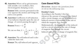
Additional questions:, 21. An electric current is passed through a circuit containing two wires of, same material, connected in parallel. If the lengths and radii of the wires, are in the ratio of 3:2 and 2:3, then the ratio of the current passing, through the wire will be, a., , 2:3, , b. 3:2, , c. 8:27, , d. 27:8, , Ans: optin 3, 8:27 as I inversely depends on R in parallel and R proportional to L/r2, 22. From the graph between current I and voltage V shown below, identify the portion, corresponding to negative resistance., I, , E, , C, B, A, , a. AB, , b. BC, , D, v, , c. CD, , d. DE, , Ans: Option C, CD this is the region where current is falling with raise in voltage, 23. Two wires of same material have length L and 2L and cross-sectional areas 4A and A, respectively. The ratio their specific resistance would be:, a. 1 : 2, b. 8 : 1, c. 1 : 8, d. 1 : 1, Ans: Option d. as both materials being same, specific resistance remains same, 24. Two cells of emf’s approximately 5V and 10V are to be accurately compared using a, potentiometer of length 400m., a. The battery that run the potentiometer should have voltage of 8 V, b. The battery of potentiometer can have a voltage of 15V and R adjusted so that, the potential drop across the wire slightly exceeds 10V, c. The first portion of 50cm of wire itself should have a potential drop of 10V, d. Potentiometer is usually used for comparing resistance and not voltages., Ans: Option B: driving battery emf should always more than the emf of secondary, cells, 25. A 220V-100W bulb is connected to a source of 180V. the power consumed by it will be, nearly :, a. 32 w, b. 67 W, c. 100 W, d. 75 W, 25
Page 26 :
Ans: Option b: 67 W, Pc = Vap2 Pactual/Vactual2 = (1802 x 100)/2202 = 66.9 = 67 W, , Chapter 4: Magnetic effect of electric current, MCQ’s, 1. Which of the following statements is correct?, (a) A charged particle can be accelerated by a magnetic field., (b) A charged particle cannot be accelerated by a magnetic field., (c) The speed of a charged particle can be increased by a uniform magnetic field., (d) The speed of a charged particle can be increased by a nonuniform magnetic field., , 2. A proton moves horizontally towards a vertical conductor carrying a current upwards. It will, be deflected, (a) to the left, (b) to the right, (c) upwards, (d), downwards, 3.A proton and an Alpha-particle with the same kinetic energy are moving in circular, trajectories in a constant magnetic field. If rp and ra denote respectively the radii of the, trajectories of these particles,, (a) rp > ra, 2, = ra, , (b) rp = ra, , (c) rp < ra, , (d) rp, , 4.A circular loop of area 1cm2, carrying a current of 10A is placed in a uniform magnetic field, of 0.1T perpendicular to the plane of the loop. The force on the loop due to magnetic field is, A) Zero, , b)10-4N, , c) 10-2N, , d) 1 N, , 5. Two long conductors separated by a distance d carry currents I 1 and I2 in the same, direction. They exert a force F on each other. Now the current in one of them is increased to, two times and its direction is reversed. The distance is also increased to 3d. The new value of, the force between them is, A) -2F, B)F/3, C)-2F/3, D)F/3, 6. A circular coil of one turn with radius R carrying a current I has a dipole moment M. Now, the coil is opened and rewound to have two turns without altering the current. The new, dipole moment of the coil is, 26
Page 27 :
A) M/2, 4M, , B) 2M, , C) M, , D), , 7. In order to float a wire carrying current I with linear mass density µ in the air , the, direction and magnitude of magnetic field to be is (Current is passing left to right), A) µg/I into the plane, B) µg/I vertically upward, B) µg/IL into the plane, D) µg/I L vertically upward, 8.A galvanometer coil has a resistance of 100Ω and the meter shows full scale deflection for a, current of 1mA. The shunt resistance required to convert the galvanometer into an ammeter, of range 0 to 5A is about, A) 0.01 Ω, , B) 0.1Ω, , C) 0.02 Ω, , D) 0.2 Ω, , 9.An infinitely long wire carries a current I from left to right direction. A circular coil of radius R, is in contact with the wire and carries the same current in clockwise direction. What is the, magnitude and direction of net magnetic field intensity at the centre of the coil?, , I, , A), , ( 1-, , ) out of the plane of the page, , B), , ( 1-, , ) in to the plane of the page, , C), , ( 1+, , ) out of the plane of the page, , D), , ( 1+, , ) out of the plane of the page, , 10. If we increase the number of turns of the coil of the moving coil galvanometer what happens, to the sensitivity?, A)Current sensitivity remains constant but voltage sensitivity changes, B)Current sensitivity increases but voltage sensitivity remains same, C)Both of them increase, D) No change in them, 27
Page 28 :
ASSERTION AND REASON TYPE QUESTIONS:, Answer: (A) : Both are correct and reason is correct explanation of assertion., Answer: (B) : Both are correct but reason is not the correct explanation of assertion., Answer: (C) : Reason is wrong., Answer: (D) : Both are wrong., , 11. Assertion: If a charged particle is moving in a perpendicular uniform magnetic field then its K, E does not change, Reason: Velocity of the charged particle is not changing in the magnetic field, 12. Assertion: A linear solenoid carrying a current is an equivalent bar magnet, Reason: The field lines of a solenoid resemble that of a bar magnet, 13. Assertion: Magnetic field of an atom is due to both, the orbital motion and spin motion of, electrons, Reason: A moving charged particle produces magnetic field, 14. Assertion: Two electrons projected in to a uniform magnetic field at right angles with two, different velocities complete their circular paths in the same time, Reason: Time period of revolution does not depend on velocity of the charged particle, 15. Assertion: The magnetic field along the axis of a thick current carrying conductor is zero, Reason: Electric current flows only on the surface of a conductor, , SOURCE BASED QUESTIONS:, 28
Page 29 :
16., ., , 29
Page 30 :
17., , 30
Page 31 :
18., , 31
Page 32 :
19., , 20., , 32
Page 33 :
Answer Key, , Chapter 5 - Magnetism and Matter, MULTIPLE CHOICE QUESTIONS, 1. What is the dimensional formula of magnetic pole strength, a)[M0L-1T0A1], , b) )[M0L1T0A1], , C) )[M2L1T0A2], , D) )[M0L2T0A1], , 2. A wire of length 2m is bent to form a circular coil of single turn. What is its magnetic, moment in Am2 if the current in the coil is 1A, a) 2/, , /, , c) 1/, , 33, , d) 1/2
Page 34 :
3. A circular coil of wire n turns has a radius r and carries a current I . Its magnetic dipole, moment is M ., Now the coil is unwound and again rewound into a circular coil of half the initial radius, and the, same current is passed through it, then the dipole moment of this new coil is, (a)M/2, , (b)M/4, , (c)M, , (d)2M, , 4. A uniform copper wire of length L is bent into a circular coil of two turns and a, current i is passed through it. The coil now behaves like a magnetic dipole of moment, (a) iL2/16 π, (b) iL2/8 π, (c) iL2/4 π, (d) iL2/2 π, 5. The primary origin of magnetism lies in, (a) atomic current and intrinsic spin of electrons., (b) polar and non polar nature of molecules., (c) pauli exclusion principle., (d) electronegatic nature of materials., 6. The expression for magnetic moment of revolving electron is, a)evr/2, , b)(eh/4πm)n, , c)(e/2m)L, , d) all the above, , 7. The orbital speed of electron orbiting around a nucleus in a circular orbit of radius 50pm is, 2.2x10⁶m/s.Then the magnetic moment of electron is, a)8.8x10⁻²⁴Am2, , b) 1.6x10⁻¹⁹Am2, , c)8.8x10⁻³⁰Am2, , d)None of these, , 8. A closely wound solenoid of 800 turns and area of cross section 2.5×10⁻⁴m2 carries a current, of 3.0A. What is its associated magnetic moment?, a)0.5Am2, b) 0.6Am, , c) 0.5Am, , 9. Magnetic moment for solenoid and corresponding bar magnet is, (a) equal for both, (b) more for solenoid, (c) more for bar magnet, (d) none of these, 10. Point out the correct direction of magnetic field in the given figures., , 34, , d) 0.6Am2
Page 35 :
11. . The earth behaves as a magnet with magnetic field pointing approximately from the, geographic, (a) North to South, (b) South to North, (c) East to West, (d) West to East, 12. Lines of force, due to earth’s horizontal magnetic field, are, (a) elliptical, (b) curved lines, (c) concentric circles, (d) parallel and straight, 13. The earth’s magnetic field at the equator is approximately 0.4 G. What is the estimated, , value of the earth’s dipole moment is (The radius of the earth is R=6.4 x1024 m), (a) 1.05 x10²³ Am, , (b) 1.05 x10²³ Am2, (c) 2.05 x10²³ Am2, (d) 3.05 x10²³ Am2, 14. If the angles of dip at two places are 300 and 450 respectively, then the ratio of horizontal, components of earth’s magnetic field at the two places will be:, (a), , (b), , (c), , (d) 1 : 2, , 15. Which of the following statement is not correct about the magnetic field?, (a) Magnetic field lines form a continuous closed curve., (b) Magnetic field line do not interest each other., (c) Direction of tangent at any point on the magnetic field line curve gives the direction, of magnetic field at that point., , 35
Page 36 :
(d) Outside the magnet, magnetic field lines go from South to North pole of the, magnet., 16.The magnetic field lines inside a bar magnet:, (a) do not exist, (b) depends on area of cross-section of bar magnet, (c) are from N-pole to S-pole of the magnet, (d) are from S-pole to N-pole of the magnet., 17. The Direction of net magnetic field at any point in the magnetic field is-------------------------a) Always South to North at all points of the field, b) Always North to South at all points of the field, c) Tangential to the field line at that point, d) Normal to the field line at that point, 18. . What is the strength of magnetic field known as ________, a) Magnetic flux, , b) Density, , c) Intensity of magnetisation., , d) Magnetic flux density, , 19.The net magnetic flux through any closed surface, kept in a magnetic field is, (a) zero, , (b) μ0/4π, , (c) 4π/μ0, , (d) 4μ0/π, , 20.At a place the angle of dip is 30°. If the horizontal component of earth's magnetic field is, HE, then the total field intensity will be given by, (a) HE /2, , (b) 2 HE /√3, , (c) HE / √2, , (d) HE /√3, , 21.The Earth always have both horizontal and vertical components everywhere., a)True, b)False, 22.When is the angle of dip at a place equal to 45 o?, a) When the vertical and horizontal components of earth’s magnetic field are equal, b) When the vertical component is twice the horizontal component of earth’s magnetic, field, c) When the vertical component is half the horizontal component of earth’s magnetic, field, d) When either the vertical component or the horizontal components of earth’s, magnetic field is equal to zero, 23.The magnetic field of Earth can be modelled by that of a point dipole placed at the centre, of the Earth. The dipole axis makes an angle of 11.3° with the axis of Earth. At Mumbai,, ‘declination is nearly zero. Then,, (a) the declination varies between 11.3° W to 11.3° E., 36
Page 37 :
(b) the least declination is 0°., (c) the plane defined by dipole axis and Earth axis passes through Greenwich., (d) declination averaged over Earth must be always negative., 24.Which of the following is responsible for the earth’s magnetic field?, (а) Convective currents in earth’s core, (б) Diversive current in earth’s core., (c) Rotational motion of earth., (d) Translational motion of earth., 25 How many quantities are required to specify the magnetic field of the earth?, a). 1, b). 2, c). 3, d). 4, 26.. Which of the following is the definition for magnetic meridian of Earth?, a) Vertical plane passing through the axis of a freely suspended or pivoted magnet, b) Horizontal plane passing through the axis of a freely suspended or pivoted magnet, c) Vertical plane passing through the geographical North Pole and South Pole at a given, place, d) Horizontal plane passing through the geographical North Pole and South Pole at a, given place, 27. Which among the following is denoted by δ?, a) Horizontal component, b) Magnetic meridian, c) Magnetic declination, d) Magnetic inclination, 28. A long magnet is cut into two parts such that the ratio of their lengths is 2:1. What is the ratio, pole strength of both the section?, a., b., c., d., , 1:2, 2:1, 4:1, Equal, , 29.Which of the following statements is true about magnetic field intensity?, a. Magnetic field intensity is the number of lines of force crossing per unit volume., b. Magnetic field intensity is the number of lines of force crossing per unit area., c. Magnetic field intensity is the magnetic induction force acting on a unit magnetic, pole., d. Magnetic field intensity is the magnetic moment per unit volume., 30.. What happens to the magnetic moment if a hole is made at the centre of a bar magnet?, , 37
Page 38 :
a. Decreases, b. Increases, c. Does Not change, d. None of the above, , e. II Assertion and Reasoning type of questions, Directions for assertion & reason questions, These questions consist of two statements each , printed as assertion and reason. while, answering these questions you have to choose any one of the following four responses., (A) if both assertion& reason are true &the reason is a correct explanation of the assertion., (B) if both assertion& reason are true but the reason is not a correct explanation of the, assertion., (C) if assertion is true but the reason is false., (D) if assertion is false but reason is true, , 31 . Assertion : When radius of a circular loop carrying current is doubled, its magnetic, moment, becomes four times., Reason : Magnetic moment depends on area of the loop., 32. Assertion :The magnetic moment (μ) of an electron revolving around the nucleus decreases with, increasing principle quantum number (n)., Reason :Magnetic moment of the revolving electron μ n, 33. Assertion : The magnetic field produced by a current carrying solenoid is independent of, its, length and cross-sectional area., Reason, : The magnetic field inside the solenoid is uniform., 34. Assertion :The ends of a magnet suspended freely point out always along north south direction., Reason, , : Earth behaves as a huge magnet., , 35. Assertion :The angle of dip is maximum at the poles of the earth., Reason, , :The magnetic field lines are parallel to the surface of the earth at the poles., KEY FOR THE QUESTIONS, , 1. b, , 2.c, , 3.a, , 4.b, , 5.a, , 6.d, , 7.a, , 8.d, , 9.a, , 10.d, , 11.b, , 12.d, , 13.b, , 14.a, , 15.d, , 38
Page 39 :
16.d, , 17. c, , 18.d, , 19.a, , 20.b, , 21.b, , 22.a, , 23.a, , 24.a, , 25.c, , 26.a, , 27.d, , 28.d, , 29.c, , 30.c, , 31.b, , 32.d, , 33.b, , 34.a, , 35.c, , Hints:, 2. Length of the wire =2m, when bent becomes circumference (c) of the loop, whose radius is given by, :, r=c/2 π=(2/2 π)=(1/ π), Thus, area of loop :A=πr2=π(1/π)2=1/π m2, So, the magnetic moment of the loop in,, M=IA=(1/π)Am2., , 3., , 39
Page 40 :
4., , 7., , 40
Page 41 :
8., Given: n=800,, A=2.5×10⁻⁴m2,, I=3.0A, A magnetic field develops along the axis of the solenoid. Therefore current-carrying solenoid acts like a, bar magnet., m=nIA=800×3×2.5×10−4, =0.6Am2 along the axis of the solenoid., 13.Bequatorial=μ0/4π×M/d3⇒, Here μ0 is the permeability of free space, M is the dipole moment of the magnet, d is the, distance of the point from the equator of the magnet, and, Bequatorials the magnetic field of the magnetic field at the equator of the magnet., for any point on the equator d=R=6400Km=6400×103m, Also, the value of the magnetic field is given as, ⇒B=0.4G=0.4×10⁻⁴,T, On calculation, Earth’s dipole moment at the equator will be 1.05×10²³Am2, , 41
Page 42 :
14, , 20A, , Chapter 6 - ELCTRO MAGNETIC INDUCTION, 1) Lenz’s law of electromagnetic induction is as per law of conservation of, (a) energy., (b) angular momentum., (c) charge., (d) electromotive force., , 42
Page 43 :
2) Which of the following statements is not correct?, (a) Whenever the amount of magnetic flux linked with a circuit changes, an emf is, induced in circuit., (b) The induced emf lasts so long as the change in magnetic flux continues., (c) The direction of induced emf is given by Lenz’s law., (d) Lenz’s law is a consequence of the law of conservation of momentum., 3) Which of the following does not use the application of eddy current?, (a) Electric power meters, (b) Induction furnace, (c) LED lights, (d) Magnetic brakes in trains, 4) A metallic rod of length ' L' is rotated with a angular frequency of ' ω ' , with one, end hinged at the centre and the other end at the circumference of circular, metallic ring of radius 'R’, about an axis passing through the centre and, perpendicular to the plane of the ring as shown in the figure. A constant and, uniform magnetic field 'B' parallel to the axis is present everywhere. What is the, emf between the centre and the metallic ring?, , a), BωR )/2, b) ( Bω2R )/2, c) ( BωR2)/2, d) ( B2ωR)/2, 5), In the given figure current from A to B in the straight wire is increasing., of the induced current in the loop is, , (a) clockwise., (b) anticlockwise., (c) straight line., (d) no induced e.m.f. produced., 6), , A rod PQ of length 'L' is moved in uniform magnetic field 'B’ as shown., 43, , The direction
Page 44 :
If the rod is moving with a velocity 'v' making an angle 'θ' with the, magnetic field. What will be the emf induced in it?, , a) BLvsinθ, b) BLvcosθ, c) BLv, d) BLvtanθ, 7), When current in a coil changes from 5 A to 2 A in 0.1 s, averagevoltage of 50, produced. The self-inductance of the coil will be., , V is, , (a) 1.67 H, (b) 6 H, (c) 3 H, (d) 0.67 H, 8), The north pole of a long bar magnet was pushed slowly into a short, solenoid, connected to a galvanometer. The magnet was heldstationary for a few seconds with, the north pole in the middle of the solenoid and then withdrawn rapidly. The maximum, deflection of the galvanometer was observed when the magnet was, (a) moving towards the solenoid, (c) at rest inside the solenoid, , (b) moving into the solenoid, (d) moving out of the solenoid, , 9), If number of turns in primary and secondary coils is increased to two times each, the, mutual inductance., (a) becomes 4 times, (b) becomes 2 times, (c) becomes 8 times, (d) remains unchanged, 10), A cylindrical bar magnet is rotated about its axis (Figure). A wire is, connected, from the axis and is made to touch the cylindrical surface through a contact. Then, , 44
Page 45 :
(a) A direct current flow in the ammeter A., (b) No current flows through the ammeter A., (c) An alternating sinusoidal current flow through the ammeter A with a time, = 2πω, (d) A time varying non-sinusoidal current flows through the ammeter., 11), , 12), , period T, , The polarity of the induced emf is given by, a) Ampere' circuital law, b) Biot- Savart Law, c) Lenz's law, d) Fleming's right-hand rule, Which of the following statements is correct?, a) The induced e.m.f is not in the direction opposing the change in magnetic flux so as, to, oppose the cause which produces it., b) The relative motion between the coil and magnet produces change in magnetic flux, c) EMF is induced only if the magnet is moved towards coil., d) EMF is induced only if the coil is mover towards magnet., , 13) SI unit of magnetic flux, a) weber, b) tesla x meter, c) tesla, d) Gauss, 14) Flux is a, a) Vector quantity, b) Scalar quantity, c) Phasor, d) negative quantity, 15) Which of the following statements is wrong for magnetic flux, a) Magnetic flux can be negative, b) Magnetic flux can be positive, c) Magnetic flux can be zero, d) Magnetic flux is always positive or negative., Assertion and Reason questions, Each question contains Assertion and Reason. Each question has 4 choices (A), (B), (C) and (D), out of which ONLY ONE is correct. Select the correct choice:, Choices are:, (A) Assertion is True, Reason is True and Reason is a correct explanation for Assertion., (B) Assertion is True, Reason is True but Reason is NOT a correct explanation for, Assertion., (C) Assertion is True, Reason is False., (D) Assertion isFalse, Reason is False., 16) Assertion: The bar magnet falling vertically along the axis of the horizontal coil, 45
Page 46 :
will be having acceleration less than 'g', , Reason: Clock wise current is induced in the coil, 17), Assertion: The presence of large magnetic flux through a coil maintains a current, the coil, if the circuit is continuous., , in, , Reason:Only a change in magnetic flux will maintain an induced current in the coil., 18), Assertion: If a coil is rotated in uniform magnetic field about an axis perpendicular to, the, field, emf induced in coil is maximum for orientation of coil in which magnetic flux, through, the coil is zero., Reason:Work done to rotate the coil will get converted into electrical energy., 19), , Assertion: Magnetic flux linked to closed surface is zero., Reason:Direction of induced current due to change of magnetic flux is given by, Faraday’s Law., , 20), , Assertion: When two coils are wound on each other, the mutual induction between, the coils is maximum., Reason:Mutual induction does not depend on the orientation of the coils., , 46
Page 47 :
Q.NO, 1), 2), , KEY, CH - 6, E M Induction, Answer, Explanation, Against to the opposing force work is done. The work, (a) energy, done by the external agency get converted in to, Electrical energy., (d) Lenz’s law is a, Conservation of Angular momentum ( I x ω =, consequence of the, constant) has nothing to do with Lenz's law, law of conservation of, momentum., , 3), , (c) LED lights, , Eddy current cannot make an LED glow., , 4), , c) (BωR2)/2, , Simple derivation, , 5), , (a) clockwise., , According to Lenz's law, , 6), , a) BLvsinθ, , 7), , a) 1.67 H, , 8), , (d) moving out of the, solenoid, , The component of velocity which contribute to the, motional emf is v sinθ, e = - L , By substituting the values of e, dI , dt the, value of L can be calculated., As the magnet is pulled out with maximum velocity, the emf generated is also proportionately more., , 9), 10), 11), , (a) becomes 4 times, (a) a direct current, flow in the ammeter A., c) Lenz's law, , Mutual Inductance is µ0 n1 n2 π r2 l, As there is no variation of θ the current generated is, DC, Lenz's law gives the polarity of induced emf, , 12), 13), , b), a) Weber, , All other statements are wrong, Wb is the unit of magnetic flux, , 14), , b) Scalar quantity, , Flux is a dot product of B and A, , 15), , d), , 16), , c) Assertion is true but, the reason is false., , 17), , d) Both Assertion and, Reason are wrong, , 18), , b) Both the statements, are individually true, c) Assertion is True,, but reason is false, , Flux can be zero even. It is neither positive nor, negative, Due to change of flux, anticlockwise current is, induced in the coil. Which opposes the motion of the, magnet of the magnet and so a < g, If there is no change in the magnetic flux linked with, the coil, there is no induced current., The current induced in a coil is directly proportional, to the rate of change of magnetic flux linked with the, coil, Reason is not relevant for Assertion, , 19), , Faraday's law doesn't explain the direction of current, 47
Page 48 :
20), , c) Assertion is True but, reason is false, , Mutual induction depends on orientation of coils., , SECTION -A, 1) Lenz's law is consequence of the law of conservation of, (a) Charge, , (b) Momentum, , (c) Mass, , (d) Energy, , 2) The magnetic flux through a circuit of resistance R changes by an amount in time t ,, Then the total quantity of electric charge Q , which passing during this time through any point, of the circuit is given, , t, , (a), , Q, , (c), , Q, , , R, t, , (b), , Q, , , R, t, , (d), , Q, , , R, , 3) A copper ring is held horizontally and a bar magnet is dropped through the ring with its, length along the axis of the ring. The acceleration of the falling magnet while it is passing, through the ring is, (a) Equal to that due to gravity, (b) Less than that due to gravity, (c) More than that due to gravity, (d) Depends on the diameter of the ring and the length of the magnet, 4) In a coil of area 10 cm 2 and 10 turns with a magnetic field directed perpendicular to the, plane and is changing at the rate of, current in the coil will be, , 10 8 gauss/second., , (a) 5 amp, , (b) 0.5 amp, , (c) 0.05 amp, , (d), , The resistance of the coil is 20 ohm. The, , 5 10 8 amp, , 5) A 10 metre wire kept in east-west falling with velocity 5 m/sec perpendicular to the field, 0.3 10 4 Wb / m 2 . The induced e.m.f. across the terminal will be, (a) 0.15 V, , (b) 1.5 mV, , (c) 1.5 V, , (d) 15.0 V, , 6) A metal rod moves at a constant velocity in a direction perpendicular to its length. A, constant uniform magnetic field exists in space in a direction perpendicular to the rod as well, as its velocity. Select the correct statement(s) from the following, (a) The entire rod is at the same electric potential, (b) There is an electric field in the rod, 48
Page 49 :
(c ) The electric potential is highest at the centre of the rod and decreases towards its end, (d)The electric potential is lowest at the centre of the rod and increases towards its end, 7) A wheel with ten metallic spokes each 0.50 m long is rotated with a speed of 120 rev/min in a, plane normal to the earth’s magnetic field at the place. If the magnitude of the field is 0.4 Gauss,, the induced e.m.f. between the axle and the rim of the wheel is equal to, (a) 1 .256 10 3 V, , (b) 6 .28 10 4 V, , (c) 1 .256 10 4 V, , (d) 6 .28 10 5 V, , 8) An e.m.f. of 5 volt is produced by a self inductance, when the current changes at a steady, rate from 3 A to 2 A in 1 millisecond. The value of self inductance is, (a) Zero, , (b) 5 H, , (c) 5000 H, , (d) 5 mH, , 9) A 50 mH coil carries a current of 2 ampere. The energy stored in joules is, (a) 1, (b) 0.1, (c) 0.05, (d) 0.5, 10) The number of turns in the coil of an ac generator is 5000 and the area of the coil is, 0 . 25 m 2 . The coil is rotated at the rate of 100 cycles/sec in a magnetic field of 0.2 W / m 2 . The, peak value of the emf generated is nearly, (a) 786 kV, (c) 220 kV, , (b) 440 kV, (d) 157.1 kV, , 11) The core of a transformer is laminated to reduce energy losses due to, (a) Eddy currents, , (b) Hysteresis, , (c) Resistance in winding (d), , None of these, , 12) The inductance of a solenoid 0.5 m long of cross-sectional area 20 cm2 and with 500 turns, is, (a) 12.5 mH, , (b) 1.25 mH, , (c) 15.0 mH, , (d) 0.12 mH, , 13) The number of turns of primary and secondary coils of a transformer are 5 and 10, respectively and the mutual inductance of the transformer is 25 henry. Now the number of, turns in the primary and secondary of the transformer are made 10 and 5 respectively. The, mutual inductance of the transformer in henry will be, (a) 6.25, , (b) 12.5, , (c) 25, , (d) 50, SECTION –B, 49
Page 50 :
DIRECTIONS FOR ASSERTION & REASON QUESTIONS, These questions consist of two statements each , printed as Assertion and Reason. While, answering these Questions you are requested to choose any one of the following four, responses., (E), , IF BOTH ASSERTION& REASON ARE TRUE &THE REASON IS A CORRECT EXPLANATION OF, THE ASSERTION., (F) IF BOTH ASSERTION& REASON ARE TRUE BUT THE REASON IS NOT A CORRECT, EXPLANATION OF THE ASSERTION., (G) IF ASSERTION IS TRUE BUT THE REASON IS FALSE., (H) IF ASSERTION IS FALSE BUT REASON IS TRUE, 14) Assertion: Whenever magnetic flux linked with the coil changes with respect to time,then, an emf is induced in it., Reason: According to Lenz’s law ,the direction of induced current in any coil in such a way that, it always opposes the cause by which it is produced., 15) Assertion: A small magnet takes longer time in falling in a hollow metallic tube with out, touching the wall., Reason: There is opposition of motion due to production of eddy currents in a metallic tube., 16) Assertion: On moving a straight wire of copper in a uniform magnetic field cutting the lines, of force, an emf is induced between the ends of the wire., Reason : The Lorentz force acts on the free electrons of copper wire when moved in magnetic, field ., 17) Assertion: The phenomenon of self induction is helpful in working of a choke coil ., Reason : A choke coil is used for reducing energy loss in the circuit ., 18) Assertion: When two coils are wound on each other ,the mutual induction between the, coils is maximum ., Reason :Mutual induction does not depend on the orientation of the coils ., , KEY AND SOLUTIONS (FOR CHAPTER 6. E.M.I ), SECTION-A, 1., , (d) The energy of the field increases with the magnitude of the field. Lenz’s law infers that there, is an opposite field created due to increase or decrease of magnetic flux around a conductor, so as to hold the law of conservation of energy., , 50
Page 51 :
2., , (b) We know that e d, dt, , But e=iR and i dq dq R d dq d , dt, , 3., , dt, , dt, , R, , (b) When the magnet is allowed to fall vertically along the axis of loop with its north pole, towards the ring. The upper face of the ring will become north pole in an attempt to oppose, the approaching north pole of the magnet. Therefore the acceleration in the magnet is less, than g., Note : If coil is broken at any point then induced emf will be generated in it but no induced, current will flow. In this condition the coil will not oppose the motion of magnet and the, magnet will fall freely with acceleration g. (i.e. a = g), S, N, , a=g, , e N d / dt 10 10 8 10 4 10 4 10, , , R, R, 20, , 4., , (a) I , , 5., , (b) Induced e.m.f., , =5A, , Blv 0 .3 10 4 10 5, , 1 . 5 10 3 V 1 . 5 mV, , 6., , (b) A motional emf e Bvl is induced in the rod, or we can say, a potential difference is induced, between the two ends of the rod , with P at higher potential and Q at lower potential. Due to this, potential difference, there is an electric field in the rod., ×, , ×, , ×, , ×, , ×, , ×, , ×, , ×, , P, , , , ×, , B, , ×, , l, , ×, , ×, , v, ×, , ×, , ×, , ×, , Q, , 7., , (d), , e Bl 2 0 .4 10 4 (0 .5)2 (3 .14 ) , , 120, 60, , 6.28 10 5 V, , e, 5, 5, , 10 3 5milli henry, di / dt (3 2) / 10 3, 1, , 8. (d), , L, , 9. (b), , Energy stored E Li 2 50 10 3 4 0.1 J, , 1, 2, , 1, 2, , 10. (d) e 0 NBA (2 ) NBA, 2 3 . 14 1000 5000 0 . 2 0 . 25 = 157 kV, , 11. (a) Circulation of eddy currents is prevented by use of laminated core., 51
Page 52 :
12. (b) S L , 13. (c), , 0 N 2 A, , M, , l, , , , 4 10 7 500 2 20 10 4, 0.5, , =1.25mH, , 0 N 1 N 2 A, l, , SECTION-B, 14. (B), , 15. (A), , 16. (A), , 17. (B), , 18. (C), , SECTION –C, CASE STUDY QUESTIONS AND ANSWERS, CH 6.EMI, 19), Lenz’s law states that ,The induced electromotive force with different polarities induces a current, whose magnetic fieldopposes the change in magnetic flux through the loop in order to ensure that, original flux is maintained through the loop when current flows in it., , To better understand Lenz‟s law, let us consider two cases:, Case 1: When a magnet is moving towards the coil., , When the north pole of the magnet is approaching towards the coil, the magnetic flux linking, tothe coil increases. According to Faraday‟s law of electromagnetic induction, when there is, a change in flux, an EMF, and hence current is induced in the coil and this current will, create its own magnetic field., Now according to Lenz‟s law, this magnetic field created will oppose its own or we can say, opposes the increase in flux through the coil and this is possible only if approaching coil side, attains north polarity, as we know similar poles repel each other. Once we know the magnetic, polarity of the coil side, we can easily determine the direction of the induced current by, applyingright hand rule. In this case, the current flows in the anticlockwise direction., Case 2: When a magnet is moving away from the coil, , 52
Page 53 :
When the north pole of the magnet is moving away from the coil, the magnetic flux linking to, the coil decreases. According to Faraday‟s law of electromagnetic induction, an EMF and hence, current is induced in the coil and this current will create its own magnetic field., Now according to Lenz‟s law, this magnetic field created will oppose its own or we can say, opposes the decrease in flux through the coil and this is possible only if approaching coil side, attains south polarity, as we know dissimilar poles attract each other. Once we know the, magnetic polarity of the coil side, we can easily determine the direction of the induced current by, applying right hand rule. In this case, the current flows in a clockwise direction., Note that for finding the directions of magnetic field or current, use the right-hand thumb, rule i.e if the fingers of the right hand are placed around the wire so that the thumb points, in the direction of current flow, then the curling of fingers will show the direction of the, magnetic field produced by the wire., , 53
Page 54 :
1. What is the direction of the induced magnetic field?, , (a) Left, (b) right, (c) up, (d) down, Ans. (a) left, 2. What is the direction of the induced magnetic field?, , (a) left, (b) right, (c) up, (d) down, Ans. (d) down, 3. In what direction is the magnet moving?, , (a) left, (b) right, 54
Page 55 :
(c) up, (d) down, Ans. (b) right, 4. In what direction is the magnet moving?, , (a) left, (b) right, (c) up, (d) down, Ans. (a) left, 5. Which of the following is NOT an application of Lenz's Law, , (a)Transformer, (b) AC Generator, (c) DC Motor, (d) A coil transversed by AC current, Ans.(c) DC Motor, 20), According to Faraday’s law of electromagnetic induction, there will be an EMF induced in the, second winding. If the circuit of this secondary winding is closed, then a current will flow, through it. This is the basic working principle of a transformer., Let us use electrical symbols to help visualize this. The winding which receives electrical power, from the source is known as the „primary winding‟. In the diagram below this is the „First Coil‟., The winding which gives the desired output voltage due to mutual induction is commonly known, as the „secondary winding‟. This is the „Second Coil‟ in the diagram above., , 55
Page 56 :
A transformer that increases voltage between the primary to secondary windings is defined as a, step-up transformer. Conversely, a transformer that decreases voltage between the primary to, secondary windings is defined as a step-down transformer., Whether the transformer increases or decreases the voltage level depends on the relative number, of turns between the primary and secondary side of the transformer., If there are more turns on the primary coil than the secondary coil than the voltage will decrease, (step down)., If there are less turns on the primary coil than the secondary coil than the voltage will increase, (step up)., While the diagram of the transformer above is theoretically possible in an ideal transformer – it, is not very practical. This is because in the open air only a very tiny portion of the flux produced, from the first coil will link with the second coil. So the current that flows through the closed, circuit connected to the secondary winding will be extremely small (and difficult to measure)., The rate of change of flux linkage depends upon the amount of linked flux with the second, winding. So ideally almost all of the flux of primary winding should link to the secondary, winding. This is effectively and efficiently done by using a core type transformer. This provides, a low reluctance path common to both of the windings., 1. The secondary winding of which of the following transformers is always kept closed?, , (a)Current transformer, (b)Voltage transformer, (c)Power transformer, (d)Step down transformer, Ans. (a) Current Transformer, 2. If the supply frequency of a transformer increases, the secondary output voltage of, thetransformer, (a) Increase, ( b)Decrease, (c)Remain the same, (d)Any of the above, Ans.(c) Remain the same, , 3. The open-circuit test in a transformer is used to, measure(a)Copper loss, (b)Winding loss, 56
Page 57 :
(c)Total loss, (d)Core loss, Ans.(d) Core loss, 4. Lamination of the transformer core is made of, (a)Cast Iron, (b)Silicon Steel, (c)Aluminum, (d)Cast Steel, Ans.(b) Silicon Steel, 5. A transformer transform, (a)Current, (b)Voltage & current, (c)Frequency, (d)Voltage, Ans.(b) Voltage & current, , 21), Definition: Mutual Inductance between the two coils is defined as the property of the coil due, to which it opposes the change of current in the other coil, or you can say in the neighbouring, coil. When the current in the neighbouring coil changes, the flux sets up in the coil and, becauseof this, changing flux emf is induced in the coil called Mutually Induced emf and the, phenomenon is known as Mutual Inductance., The value of Mutual Inductance (M) depends upon the following factors, 1. Number of turns in the secondary or neighboring coil, 2. Cross-sectional area, 3. Closeness of the two coils, , 57
Page 58 :
Mutual Coupling In the Magnetic Circuit, When on a magnetic core, two or more than two coils are wound, the coils are said to be mutually, coupled. The current, when passed in any of the coils wound around the magnetic core, produces flux, which links all the coils together and also the one in which current is passed., Hence, there will be both self-induced emf and mutual induced emf in each of the coils., The best example of the mutual inductance is the transformer, which works on the principleof, Faraday‟s Law of Electromagnetic Induction., Faraday‟s law of electromagnetic induction states that “ the magnitude of voltage is directly, proportional to the rate of change of flux.” which is explained in the topic Faraday‟s Law of, Electromagnetic Induction., 1. The phenomenon due to which there is an induced current in one coil due to current in a, neighbouring coil is?, A. Electromagnetism, B.Susceptance C.Mutual, inductance, D.Steady current, Ans. (c) Mutual Inductance, 2. Mutual inductance between two magnetically coupled coils depends on, A. Permeability of the core material, B. Number of turns of the coils, C. Cross sectional area of their common core, D. All of the aboveAns. (D), 3. Which of the following is unit of inductance?, A. Ohm, B. Henry, C. Ampere turns, D. Webers/meter, Ans. (B) Henry, 4. Which of the following circuit elements will oppose the change in circuit current?, A. Capacitance, B. Inductance, C. Resistance, D. All of the above, Ans.(B) Inductance, 5. If in an iron cored coil the iron core is removed so as to make the air cored coil, the, inductance of the coil will be, , 58
Page 59 :
A. More, B. Less, C. The same, D. None of these, Ans.(B) Less, _____________________________________________________________________________, , Chapter 7: ALTERNATING CURRENT CIRCUITS, MCQ’s, 1. In an ac circuit, V and I are given by V = 100 sin (100t) Volt,, , mA. The power, , dissipated in the circuit is, (a) 104 watt, , (b) 10 watt, , (c)2.5 watt, , (d)5 watt, , Ans: c, P = Vrms Irms Cos θ, 2. An alternating e.m.f. is applied to purely capacitive circuit. The phase relation between e.m.f. and, current flowing in the circuit is, (a) e.m.f. is ahead of current by / 2, (b) Current is ahead of e.m.f. by / 2, (c) Current lags behind e.m.f. by , (d) Current is ahead of e.m.f. by , Ans: b, 3. Voltage and current in an ac circuit are given by V = 5 sin (100πt - 300) and I = 4 sin(100πt+300), (a) Voltage leads the current by, , 30 o, , (b) Current leads the voltage by, , 30 o, , (c) Current leads the voltage by, , 60 o, , (d) Voltage leads the current by, , 60 o, , Ans: c, 4. The given figure shows the variation of V and I vs t for a circuit element connected to A.C mains., Name the circuit element, , (a) Resistance, (b) Capacitor, 59
Page 60 :
(c) Inductor, Ans: b, Capacitor, 5.In a series LCR Series circuit, the voltages across Inductor, capacitor and Resistances are 20V,20V,40V, respectively. The phase difference between the supplied voltage and current in the circuit is, (a) 300, , (b) 600, , (c) 900, , (d) 00, , Ans: d, Since voltage across Inductor and capacitor are same, circuit is in resonance. Phase difference is 0 0, 6. If an, , resistance and, , 8, , 6, , reactance are present in an ac series circuit then the impedance of the, , circuit will be, (a) 20 ohm, , (b) 5 ohm, , (c) 10 ohm, , (d), , 14 2, , ohm, , Ans: (c), Ans Z2 =R2 + X2, , X1, , Frequency, , Impedance, , Impedance, , 7. The graphs given below depict the dependence of two reactive impedances X1 and X2 on the frequency, of the alternating e.m.f. applied individually to them. We can then say that, , X2, , Frequency, , (a) X1 is an inductor and X2 is a capacitor, (b) X1 is a resistor and X2 is a capacitor, (c) X1 is a capacitor and X2 is an inductor, (d) X1 is an inductor and X2 is a resistor, Ans: (c), For capacitor, Capacitative Reactance is inversely proportional to frequency, and For Inductor, Inductive Reactance is directly proportional to frequency, 8. In the circuit given below, what will be the reading of the voltmeterV, , 100V, , 100V, , 200V, 100 Hz, , (a)200V, , (b) 100 V (c) 300V, , (d) 400V, , Ans: (a), V2 = VR2 + (VL-Vc)2, 9. A capacitor has capacitance C and reactance X, If the capacitance and frequency become double, then, reactance will be, (a) 4X (b) X/2, (c) X/4, (d) 2x, 60
Page 61 :
Ans: (c), X α (1/fC), 10. A capacitor acts as an infinite resistance for, (a) DC (b) AC (c) Both DC and as well as AC (d) Neither for AC nor DC, Ans: (a), For DC Frequency is zero, 11. High Voltage transmission line is preferred as, (a) its electric appliances are less costly, (b) Thin power cables are required, (c) Idle current is low, (d) Power losses is low, Ans: (d), Power losses is low, 12. In a series LR circuit, XL = R and power factor of the circuit is P1 . When capacitor with capacitance C is, such that is put in series, the power factor becomes P2 . The ratio of P1/P2 is, (a) 2:1, (b) 1: √2, (c) √2 : 1, (d) 1: 2, Ans: (b), Hint: Power factor P = R/Z, For LR circuit, P1 = 1/√2, For LCR Series circuit P2 = 1, Read the assertion and reason carefully to mark the correct option out of the options given below:, (a) If both assertion and reason are true, the reason is the correct explanation of the assertion, (b) If both assertion and reason are true, the reason is the not correct explanation of the assertion, (c) If assertion is true but reason is false, (d) If the assertion and reason both are false, 13. Assertion :, An inductance and a resistance are connected in series with an ac circuit. In this, circuit the current and the potential difference across the resistance lag behind potential difference across, the inductance by an angle /2., Reason : In LR circuit voltage leads the current by phase angle which depends on the value of, inductance and resistance both., Ans: b, 14. Assertion : A capacitor of suitable capacitance can be used in an ac circuit in place of the choke coil., Reason : A capacitor blocks dc and allows ac only., Ans: b, 61
Page 62 :
15. Assertion, , :, , Capacitor serves as a block for dc and offers an easy path to ac., , Reason : Capacitive reactance is inversely proportional to frequency., Ans: a, 16. Assertion : When capacitive reactance is smaller than the inductive reactance in LCR current, e.m.f., leads the current ., Reason : The phase angle is the angle between the alternating e.m.f. and alternating current of the, circuit., Ans: b, 17. Assertion: Direct current is more dangerous than Alternating current of same value., Reason: An electrocuted person sticks to direct current line. While alternating current repels the person, from the line., Ans: d, 18. Assertion: A transformer can’t work on DC supply, Reason -- DC changes neither in magnitude nor in direction, Answer - A, CASE STUDY EXPERIMENT:, According to Faraday’s law of electromagnetic induction, there will be an EMF induced in the second, winding. If the circuit of this secondary winding is closed, then a current will flow through it. This is the, basic working principle of a transformer., A transformer that increases voltage between the primary to secondary windings is defined as a step-up, transformer. Conversely, a transformer that decreases voltage between the primary to secondary windings, is defined as a step-down transformer., Ideal transformer is not very practical. This is because in the open air only a very tiny portion of the flux, produced from the first coil will link with the second coil. So the current that flows through the closed, circuit connected to the secondary winding will be extremely small (and difficult to measure)., The rate of change of flux linkage depends upon the amount of linked flux with the second winding. So, ideally almost all of the flux of primary winding should link to the secondary winding. This is effectively and, efficiently done by using a core type transformer. This provides a low reluctance path common to both of, the windings., 19. If the supply frequency of a transformer increases, the secondary output voltage of the transformer, (a) Increase (b) Decrease (c) Remains the same (d) any of the above, Ans.(c) Remain the same, 20. Which quantity is increased in step-down transformer ?, (a) resistance (b) power (c) current (d) charge, Ans: c, 21. The voltage in the secondary coil of a transformer does not depend upon, (a) Frequency of the source, (b) Voltage in Primary, (c) Ratio of no. of turns in the two coils, (d) Both (b) and (c), Ans: a, 62
Page 63 :
22. The primary winding of transformer has 500 turns whereas its secondary has 5000 turns. The primary, is connected to an ac supply of 20 V, 50 Hz. The secondary will have an output of, (a) 200 V, 50 Hz (b) 2 V, 50 Hz (c) 200 V, 500 Hz (d) 2 V, 5 Hz, Ans: (a), 23. The magnitude of the emf induced across the secondary of a transformer does not depend on, (a) the magnitude of the emf applied across the primary, (b) the number of turns in the primary, (c) the number of turns in the secondary, (d) the resistance of the primary and the secondary, Ans: d, 24. Why does stepping voltage reduce power losss?, (a) Since the resistance of the conductor decreases with increase of voltage, (b) Since current decreases with increase of the voltage, (c) Both of the above, (d) None of the above, Ans.(b), Hint: Power is directly proportional to the current., 25. The physical quantity that remains unchanged in a transformer is, (a) Voltage (b) current, , (c) Frequency (d) None of these, , 2. Electrical power transmission involves the bulk movement of electrical energy from a generating site,, such as a power station or power plant, where voltage is stepped up and distributed to electrical, substation and from electrical substation, where voltage is stepped down and, distributed to consumers or other, substations. The reason electrical power is, stepped up to these voltage levels is to make, it more efficient by reducing the I2R losses, that take place when power is transmitted., When voltage is stepped up, the current, reduces relative to the voltage so that power remains constant, thus reducing these I 2R losses., 26. Name the device which is used to transform voltage from 12kV to 400kV from power plant to, substation., A) AC generator B) Step up Transformer C) Moving coil Galvanometer D) Step down transformer, Ans: B, 27. Laminated cores are used in such devices to reduce energy loss due to:, A) Eddy currents B) Flux leakage C) Resistance of the windings, D) Hysteresis loss, Ans: A, 28. A small town with a power demand of 600 kW at 220 V is situated 20 km away from power plant, generating power at 440 V. The resistance of the two wire line carrying power is 0.4 Ω per km. If the, 63
Page 64 :
power is transmitted to the substation in the town at 12 kV which the substation steps down to 220 V, before supplying to the town, Estimate the line power loss during transmission in the form of heat., A) 400 kW, B) 40 kW, C) 600 kW D) 60 kW, Ans: B, ( I = P/V = 600000/12000 = 600/12 = 50 A,, Power loss = I2 R = 50 x 50 x R = 50 x 50 x 0.4 x 40 = 40000 W = 40 kW ), 29. High voltage transmission line is preferred as, A) Its appliances are less costly, B) Thin power cables are required, C) Idle current is very low, D) Power loss is very less, Ans: D, 30. Which of the following assumptions are used for deriving the relation:, , A) The primary resistance and current are small;, B) The same flux links both the primary and the secondary as very little flux escapes, from the core, C) The secondary current is small, D) All of the above, Ans: B, MCQ’S IN ALTERNATING CURRENTS, , Q 1., , A capacitor acts as an infinite resistance for, (a) DC, (b) AC, (c) DC as well as AC, (d) neither AC nor DC., , Q 2., , In an AC circuit current is lagging from the applied voltage then circuit can have, (a) Resistance and inductor, (b) Resistance and capacitor, (c) Both (a) and (b), (d) None of the above, , Q 3., , The peak voltage in a 220 V, AC source is, (a) 220 V, (b) about 160 V, (c) about 310 V, , Q 4., , An AC source is rated 220 V, 50 Hz. The average voltage is calculated in a time interval of 001 s. It, (a) must be zero, , Q 5., , (d) 440 V., , (b) may be zero, , (c) is never zero, , (d) is (220/2)V., , The magnetic field energy in an inductor charges form maximum value to minimum value in 50 ms, when connected to an AC source. The frequency of the source is, (a) 20 Hz, , (b) 50 Hz, , (c) 200 Hz, , 64, , (d) 500 Hz.
Page 65 :
Q 6., , In a series L, R, C, circuit which is connected to a.c. source. When resonance is obtained then net, impedance Z will be, , Q 7., , (A)Z = R, , (B), , (C)Z = L, , (D), , Z = L , Z=, , I, C, , 1, C, , A series AC circuit has resistance of 4 and a reactance of 3. The impedance of the circuit is, (a) 5, , Q 8., , (b) 7 1, , (c) 12/7, , (d) 7/12, , Transformers are used, , Q 9., , (a) in DC circuits only, , (b) in AC circuits only, , (c) in both DC and AC circuits, , (d) neither in DC nor in AC circuits, , An alternating current having peak value 14 A is used to heat a metal wire. To produce the same, heating effect, a constant current i can be used where i is, (a) 14 A, , (b) about 20 A, , (c) 7 A, , (d) about 10 A, , Q 10. A constant current of 28 A exists in a resistor. The rms current is, (a) 28 A, , (b) about 2 A, , (c) 14 A, , (d) undefined for a directed current., , CASE STUDY QUESTIONS, A series LCR circuit containing a resistance of 120 has an angular resonance frequency, 4 10 rad / sec . At resonance, voltage across resistance and inductance are 60 V and 40 V., 5, , 11., , Value of inductance is, (A) 100H, (C) 100H, , (B) 200H, (D) 200H, , 12., , The value of capacitance is, (A) 32F, (C) 1/ 32F, , (B) 16F, (D) 1/16F, , 13, , The value of XL XC , when the current lags behind the voltage by 450 is, (A) 60, (B) 120, (C) 180, (D) 240, 65
Page 66 :
, , A physics lab is designed to study the transfer of electrical energy from one circuit to another by, means of a magnetic field using simple transformers. Each transformer has two coils of wire, electrically insulated from each other but wound around a common core of ferromagnetic material., The two wires are close together but do not touch each other., , , , The primary (1°) coil is connected to a source of alternating (AC) current. The secondary (2°) coil is, connected to a resistor such as a light bulb. The AC source produces an oscillating voltage and, current in the primary coil that produces an oscillating magnetic field in the core material. This in, turn induces an oscillating voltage and AC current in the secondary coil., , , , Students collected the following data comparing the number of turns per coil (N), the voltage (V), and the current (I) in the coils of three transformers., , Primary Coil, , Transformer 1, Transformer 2, Transformer 3, 14., , V1, 10 V, , I1, 10 A, , N2, 200, , V2, 20 V, , I2, 5A, , 100, , 10 V, , 10 A, , 50, , 5V, , 20 A, , 200, , 10 V, , 10 A, , 100, , 5V, , 20 A, , (b) 50, , (c) 200, , (d) 2000, , A transformer with 40 turns in its primary coil is connected to a 120 V AC source. If 20 W of power, is supplied to the primary coil, how much power is developed in the secondary coil?, (a) 10 W, , 16., , N1, 100, , The primary coil of a transformer has 100 turns and is connected to a 120 V AC source. How many, turns are in the secondary coil if there’s a 2400 V across it?, (a) 5, , 15., , Secondary Coil, , (b) 20W, , (c) 80W, , (d) 160W, , Which of the following is a correct expression for R, the resistance of the load connected to the, secondary coil?, 66
Page 67 :
V 0, (a) 1, I0, 1, , 17., , N 20, , N 10, , , , , , V 0, (b) 1, I0, 1, , N 20, , N10, , , , , , 2, , V 0, (c) 1, I0, 1, , N 10, , N 20, , , , , , V 0, (d) 1, I0, 1, , N10, , N 20, , , , , , 2, , A 12 V battery is used to supply 2.0 mA of current to the 300 turns in the primary coil of a given, transformer. What is the current in the secondary coil if N2 = 150 turns ?, (a) zero, , (b) 1.0 mA, , (c) 2.0 mA, , (d) 4.0 mA, , SOURCE STUDY QUESTIONS, An alternating voltage (in volts) varies with time t (in seconds) as V = 200 sin (100 t) to a, series combination of resistance of 10 ohm and inductor of Inductance 5 mH . Then, , 18., , The peak value of the voltage is, (A) 200 V, (C) 141.45 V, , 19., , (B) 282.8 V, (D) 100 V, , The rms value of the voltage is, (A) 200 V, (C) 141.45 V, , 20., , (B) 282.8 V, (D) 100 V, , Inductive reactance in the circuit is, (A) 500π mΩ, , (B) 500 mΩ, , (C) 200π mΩ, , (D) 500π Ω, , Statement answers type questions:, A. Both Assertion and Reason are correct and Reason is the correct, explanation for Assertion., B. Both Assertion and Reason are correct and Reason is not the correct, , 67
Page 68 :
explanation for Assertion., C. Assertion is correct but Reason is incorrect., D. Both Reason and Assertion are incorrect., , 21., , Assertion: If the frequency of alternating current in an ac circuit consisting of an, inductance coil is increased then current gets decreased, Reason: The current is inversely proportional to frequency of alternating current., , 22., , Assertion: An alternating current does not show any magnetic effect., Reason: Alternating current does not vary with time., , 23., , Assertion: In a series LCR circuit, at resonance condition power, consumed by circuit is maximum., Reason: At resonance condition effective resistance of circuit is, maximum., , 24., , Assertion: When resistance and inductor are connected in series with AC source. Voltage lead the current in inductor., Reason: In series R, L, C circuit when connected by A-C source voltage, can lead, or lag in phase with current depends on L and C only., , 1, , (a), , 2, , (a), , 3, , (c), , 4, , (b), , 5, , (b), , 6, , (a), , 7, , (a), , 8, , (b), , 9, , (d), , 10, , (a), , 11, , D, , 12, , C, , 13, , B, , 14, , d, , 15, , b, , 16, , b, , 17, , d, , 18, , A, , 19, , C, , 20, , A, , 21, , a, , 22, , d, , 23, , d, , 24, , b, , 68
Page 69 :
69
Page 70 :
70
Page 71 :
71
Page 72 :
72
Page 73 :
73
Page 74 :
74
Page 75 :
75
Page 76 :
76
Page 77 :
77
Page 78 :
78
Page 79 :
79
Page 80 :
80
Page 81 :
81
Page 82 :
82
Page 83 :
83