Notes of 7th SEM CSE, Internet Of Things (IOT) IOT Lab Manual.pdf - Study Material
Page 1 :
INTERNET OF THINGS, LAB MANUAL, , Prepared by:, , Mrs. Farha Anjum, Assistant Professor, Department of Computer Science and Engineering, SUCET, Mukka, Mangalore, , Following lab manual of internet of things (IOT) have been written/prepared by Mrs. Farha Anjum, with grateful acknowledgement to others who made their course contents freely available. Feel free, to use this manual for your own academic purpose, For any query, the communication can be made, through my mail
[email protected], , Date: October 25,2021, , 1
Page 2 :
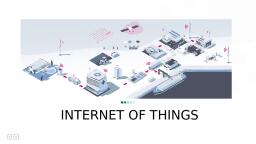
Experiment NO –1, , Title: Familiarization with the concept of IOT, Arduino / Raspberry Pi and perform necessary, software installation., Objectives: To study IOT, their characteristics of components and basic awareness of Arduino/, Raspberry Pi., Outcomes: Students will be able to understand IOT, Arduino/ Raspberry Pi, and also able to install, software setup of Arduino/ Raspberry Pi., Prerequisites: Fundamentals of Operating systems, Hardware Requirement: Arduino basic kit or Raspberry Pi starter kit, Software Requirement: Can be installed on LINUX and a stripped down IOT version of Windows, 10, Introduction:, “The Internet of Things (IOT) is the interconnection of uniquely identifiable embedded computing, devices within the existing Internet infrastructure. The Internet of Things connects devices and vehicles, using electronic sensors and the Internet”., , Figure 1: Internet of Things (IOT) basic architecture, , 2
Page 3 :
The Internet of Things (IOT) is defined as the network of physical objects, things that are embedded, with sensors, software and other technologies for the purpose of connecting and exchanging data with, other devices and systems over the internet (See Figure 1)., , The IOT is the network of physical objects, devices, vehicles, buildings and other items, embedded with electronics, software, sensors and network connectivity that enables these objects to, collect and exchange data. The IOT allows to be sensed and controlled remotely across existing network, infrastructure, creating opportunities for more direct integration of the physical world into computer, based systems, and resulting in improved efficiency, accuracy and economic benefit, when IOT is, augmented with sensors and actuators, the technology becomes an instance of the more general class of, cyber physical systems, which also encompasses technologies such as smart grids, smart homes,, intelligent transportation and smart cities. Each thing is uniquely identifiable through its embedded, computing system but is able to interoperate within the existing internet infrastructure., , So, IOT is an architecture that comprises specialized hardware boards, software systems, web, APIs, protocols which together creates a seamless environment which allows smart embedded devices, to be connected to internet such that sensory data can be accessed and control system can be triggered, over internet., , Also, devices could be connected to internet using various means like Wi-Fi, Ethernet and so, on. Furthermore, devices may not needed to be connected to the internet independently, rather than, creating a cluster of devices such as sensor network and the base station, or the cluster head could be, connected to the internet. This leads to more abstract architecture for communication protocols which, ranges from high level to low level., , Most interestingly, these devices must be uniquely discovered. For unique discovery of the, devices in a network, they need to have unique IP address. IOT devices essentially have IPv6, addressing scheme. All these devices have either fixed or subnet masked IP addresses of type v6., Unique IP addresses makes IOT devices discoverable in the internet as independent node. This is the, most important concept to have in mind to understand IOT., , Since IOT are essentially embedded systems and smart objects connected to internet with unique, IP address which can be discovered and communicated over internet. We have also seen that the IOT, devices may have external peripheral like Actuators and Sensors., , 3
Page 4 :
Embedded platform, Arduino: It is probably the best starting point for embedded based IoT. Based Arduino Boards don’t, come with Ethernet shield or Wi-Fi shield and for Arduino to be able to work as IoT device, their, need to select Arduino with Ethernet shield or Wi-Fi shield. Arduino run on the other hand is a board, that comes ported with Ethernet shield., , Raspberry Pi: It is probably one of the best things to happen in DIY (DO it Yourself) IoT. A wide, range of data driven applications like Home Automation Server to Home Multimedia server, File, Server can be developed with Pi. Pi like Arduino has general purpose IO pins. But seamless working, with sensors is bit tedious in Pi. Another efficient IoT Board is Intel Edition which has integrated, BLE, Wi-Fi among host of other features. It supports wide range of industry standard hardware (over, 30) through 70 pin interface (See Figure 2)., , Intel Galileo: It is another good offering by Intel which supports the same shielding that of Arduino, Uno. So it can be said to be first Intel powered device which is Arduino compatible. It has among, other thing a USB host controller like Raspberry Pi which makes this an attractive hardware. Galileo, also has Ethernet shield built-in., , Description of Raspberry Pi 3 Model B1. CPU: Raspberry Pi 3 uses Broadcom BCM2837 SOC 64-bit quad-core ARM Cortex A53, (ARMv8) with 512KB shared L2 cache., 2. Memory: Provided with 1GB of RAM, 3. Wi-Fi: Support 802.11n WirelessLAN, 4. Bluetooth: Supports Bluetooth 4.1 (BLE), 5. USB Ports: USB ports which allow attaching four different USB devices like keyboard,, mouse etc, , 4
Page 5 :
Figure: Raspberry Pi 3 Model B overview, , 5
Page 6 :
Figure 2: Raspberry Pi 3 Model B Block Diagram, , 6. Ethernet Port: Standard Ethernet port to quickly setup and access internet. This can be very, useful when we want to setup raspberry pi for the first time without a monitor., 7. GPIO pins: Raspberry Pi 3 supports 40 GPIO pins General Purpose Input Output. These, digital input/ output pins can be used to drive LED, Switches and Sensors etc., 8. Full HDMI Port: Support HDMI port (High-Definition Multimedia Interface) which can be, used to quickly connect raspberry pi to HDMI Monitor. With HDMI Cable and Monitor we, can add Screen to Raspberry Pi., 9. Micro SD card slot: The micro SD card will hold the operating system which will boot, while we power on Raspberry Pi 3., 10. Audio/Video: Combined 3.5mm audio jack and composite video., 6
Page 7 :
11. Display interface (DSI): Enable us to interface Display Module, 12. Camera interface (CSI): Enable us to interface Camera Module., 13. Graphics Support: VideoCore IV 3D graphics core for advance graphics capabilities., Raspberry Pi Downloads- Software for the Raspberry Pi., Raspberry Pi OS (previously called Raspian) is our official operating system for all models, of the Raspberry Pi., Use Raspberry Pi Imager for an easy way to install Raspberry Pi OS and other operating, systems to an SD card ready to use with your Raspberry Pi., •, •, •, , Raspberry Pi imager for Windows, Raspberry Pi imager for macOS, Raspberry Pi imager for Ubuntu, , Version 1.4, Install Raspberry Pi imager to Raspberry Pi OS by running, sudo apt install rpi-image in a terminal window, , Recovery, If your Raspberry Pi 4 will not boot, it is possible that the SPI EEPROM has become corrupted. To, check, remove the SD card, disconnect the device from power, then reconnect it, If the green LED, does not flash, this indicates that the EEPROM has become corrupted., , Raspberry Pi imager provides an easy way to fix this problem, by automatically preparing an SD, card that will reprogram your Raspberry Pi 4’s EEPROM., , •, •, •, •, •, •, , Find an SD card that is empty, or does not contain any data you want to keep; it will be, completely erased of all data during this process., Download Raspberry Pi imager for your operating system from the list near the top of this, page., Click “CHOOSE OS” and select “Misc utility images” then Pi 4 EEPROM boot recovery., Insert an Sd card, click “CHOOSE SD CARD”, select the card you have inserted, then click, “WRITE”., Once the SD card is ready, insert it into Raspberry Pi 4 then connect the Raspberry Pi to, power., Once complete, the green LED will blink rapidly in a steady pattern. Disconnect the device, from power. Now you can remove the recovery SD card, insert your usual SD card, and, resume using your Raspberry Pi., 7
Page 8 :
Alternatively, you can download the bootloader and create a recovery SD card manually., •, •, •, , Download the bootloader, Extract it to an empty FAT- formatted SD card and insert it into your Raspberry Pi 4., Comnect the power and wait for the green LED to flash quickly., , NOTE:, •, •, , View the full bootloader release notes., The previous bootloader remains available for download, , Raspberry Pi Desktop (for PC and Mac), Debian with Raspberry Pi Desktop is the Foundation’s operating system for PC and Mac., You can create a live disc, run it in a virtual machine, or even install it on your computer., , Connecting a Raspberry Pi to a Laptop, After purchasing a Raspberry Pi and an SD card, you might not feel like going out and buying a, display, mouse and keyboard just to create a simple project. No worries! Together, a laptop and a, internet connection are sufficient to get started on your Raspberry Pi, How?, , 1.Make Sure the OS is installed on the SD Card, Your SD might have Raspberry Pi Operating System installed. Otherwise, you can easily download, the Raspbian Operating system and install it on a blank SD card., 2. Configure the Wi-Fi Connection on your SD Card, Now you are ready to configure your SD card so that, on boot, your Raspberry Pi will connect to a, Wi-Fi network. Once the Raspberry Pi is connected to a network, you can then access its terminal via, SSH., Insert your SD card into your laptop. You should see a /boot file folder show up. First, create a file, named wpa_supplicant.conf in the /boot folder., Information like accepted networks and pre-configured network keys (such as a wi-fi password) can, be stored in the wpa_supplicant.conf text file. The file also configures wpa_supplicant the software, 8
Page 9 :
responsible for making login requests on your wireless network. So, creating the, wpa_supplicant.conf file will configure how your Raspberry Pi connects to the internet., The contents of your wpa_supplicant.conf file should look something like this:, ctrl_interface=DIR=/var/run/wpa_supplicant GROUP=netdev, update_config=1, country=US, network={, ssid=”YOURSSID”, psk=”YOURPASSWORD”, scan_ssid=1, }, The first line means “give the group ‘netdev’ permission to configure network interfaces.”, This means that any user who is part of the netdev group will be able to update the network, configuration options. The ssid should be the name of your wi-fi network, and the psk should be your, wi-fi password., After creating and updating the wpa_supplicant.conf file, add an empty SSH file in /boot. This SSH, file should not have any file extensions. When the Raspberry Pi boots up, it will look for the SSH, file. If it finds one, SSH will be enabled. Having this file essentially says, “On boot, enable SSH.”, Having SSH allow you to access the Raspberry Pi terminal over your local network., , 3. Turn on your Raspberry Pi, Put the SD card back in the Raspberry Pi, Power on., , 4. Connect to your Raspberry Pi with SSH, Make sure your laptop is on the same network as the Raspberry Pi (the network in the, wpa_supplicant.conf file). Next, you”ll want to get the IP address of the Raspberry Pi on the, network. Run arp -a to see IP address of other devices on your network. This will give you a list of, devices and the corresponding IP and MAC addresses. You should see your Raspberry Pi listed with, its IP address., Connect to the Raspberry Pi by turning ssh pi@[ the pi’s IP address]. If this is your first time logging, in, the default password should be “raspberry.” You can configure your own custom password after, the first login., You should now have access to your Raspberry Pi command line., , 9
Page 10 :
5.Install VNC Server, Now you have access to your Raspberry Pi terminal, but how do you see the Raspberry Pi desktop?, You”ll need to install a VNC Server. Running a VNC Server on your Raspberry Pi allows you to, control your Raspberry Pi desktop remotely on a laptop (the VNC viewer)., Realvnc-vnc-server worked well for me. To install, copy the following into the terminal:, sudo apt-get update, sudo apt-get install realvnc-vnc-server realvnc-vnc-viewer, After installing the VNc Server, You will need to enable it:, •, •, •, •, , Type sudo raspi-config in your terminal, A pop-up will appear; navigate to 5 “interfacing Options”, Navigate to “P3 VNC”, Select “yes”, , Raspberrypi.org also provides a step-by-step guide on how to do this., , 6. Install a VNC viewer on your laptop, Install VNC viewer from RealVNC., After installation, launch VNC viewer, and type in the IP address of your Raspberry Pi as the VNC, Server address. If you’ve forgotten its IP address, just run arp -a again. VNC Viewer will then, prompt you for the Raspberry Pi default credentials. If you have not yet configured them, the default, username is “pi” and the default password is “raspberry.”, Congratulations! You should see your Raspberry Pi desktop!, , Programming with Arduino UNO, Required Materials, To follow along with Arduino we will need the following materials. You may not need everything, though depending on what you have., •, , A computer (Windows, Mac, or Linux), , •, , An Arduino-compatible microcontroller, , 10
Page 11 :
•, , A USB A-to-B cable, or another appropriate way to connect your Arduino-compatible, microcontroller to your computer., , Figure: Basic Arduino microcontroller, , Figure: Cable for connection, , What is an Arduino?, Arduino is an open-source electronics platform based on easy-to-use hardware and software., Arduino boards are able to read inputs light on a sensor, a finger on a button., , 11
Page 12 :
Downloading the Arduino IDE, You can download the Arduino IDE from their website. They have installation instructions,, but we will also go over the installation process as well. Make sure you download the version, that matches your operating system., The installation procedure is fairly straightforward, but it does vary by OS. Here are some, tips to help you along., , Troubleshooting Tips, We recommend using a computer with a full desktop operating system like Windows 7/10, (avoid Windows 8 if you can), Mac OSX, and certain flavors Linux (check the Arduino FAQ, page for compatibility)., o If you are not a technical or computer savy individual and you have your choice of, computers, I highly recommend using a Windows 7 or 10 computer. You will usually, run into the the least issues, if any, with these operating systems., o We do NOT recommend using a Chromebook, Netbook, tablet, phone, or the Arduino, Web IDE in general. You will be responsible for troubleshooting any driver or, Arduino Web IDE issues., •, , As of the writing of this tutorial (updated 12-14-2018), the most recent and stable release of, the Arduino IDE is version 1.8.5. We recommend using that version of the Arduino IDE; you, can download the previous releases here., , •, , On Windows 10, we do NOT recommend installing the Arduino IDE from the app store. You, may run into issues because the OS will automatically update to the most recent release of the, Arduino IDE, which may have unknown bugs (like the compiler errors in versions 1.8.6 and, 1.8.7)., , •, , Raspberry Pi users with Raspbian installed should use the Linux ARM download. We do not, recommend using the command line installation. It will install the oldest release of Arduino,, which is useless when it comes to installing new boards definitions or libraries., , •, , For additional troubleshooting tips, here is a troubleshooting guide from Arduino, , Installation in Windows, How to install and test the Arduino software with a Windows operating system (Windows 10,, Windows 7, Vista, and XP)., Installer, The Windows version of Arduino is offered in two options: an installer or a zip file., The installer is the easier of the two options, just download that, and run the executable file, to begin the installation., , 12
Page 13 :
When you're prompted to install a driver during installation, select "Install". This will install drivers, for Arduino specific boards (like the Uno, Nano, etc.) that you may use in the future., , ZIP, If you choose to download the zip file version of Arduino, you'll need to extract the files yourself., Don't forget which folder you extract the files into! You will need to run the executable Arduino file, in the folder to start the Arduino IDE., When the download is finished, un-zip it and open up the Arduino folder to confirm that yes, there, are indeed some files and sub-folders inside. The file structure is important so don't be moving any, files around unless you really know what you're doing., Note: On Windows 10, there is an option to install Arduino through their app store. we do not, recommend installing the Arduino IDE from the app store. You may run into issues because the OS, , 13
Page 14 :
will automatically update to the most recent release of the Arduino IDE, which may have unknown, bugs., Connecting Your Arduino, Power up your Arduino by connecting your Arduino board to your computer with a USB cable (or, FTDI cable if you're using an Arduino Pro). You should see the an LED labeled 'ON' light up. (this, diagram shows the placement of the power LED on the UNO)., Drivers for Arduino Uno on Windows, To install the drivers for the Arduino Uno, you will need to plug in your board to your computer's, USB port. Once the board is connected, you will need to wait for Windows to begin it's driver, installation process. After a few moments, the process will probably fail, despite its best efforts., Open up a search, type in Device Manager, and hit ENTER., , Note: Searching is the easiest method to open the Device Manager. However, there is more than one, method of opening the device manager. The longer method is to click on the Start, Menu > Windows System > System and Security > System > Device Manager., Look under Ports (COM & LPT) tree. You should see an open port named "Arduino UNO, (COMxx)". If there is no COM & LPT section, look under "Other devices" for "Unknown Device., Right click on the "Arduino UNO (COMxx)" or "Unknown device" port and choose the "Update, Driver Software" option., , 14
Page 15 :
Next, choose the "Browse my computer for Driver software" option, , 15
Page 16 :
Finally, navigate to the Arduino IDE folder. This should be where you unzipped the Arduino IDE, (e.g. it should be similar to the following path with a different version number: C:\Program, Files\arduino-1.8.5\drivers). Depending on what version of Windows you have, you may be able to, select the Uno's driver file, named "Arduino.inf", located in the "Drivers" folder (not the "FTDI, USB Drivers" sub-directory). If you cannot see the *.inf file, it is probably just hidden. You can, select the "drivers" folder with the "include sub-folders" option selected instead., , 16
Page 17 :
Windows will finish up the driver installation from there! Your computer will enumerate with a, COM port. You may see a COM port number depending on what is currently saved in your, computer. Try to remember what the number is when uploading. If not, you can always navigate, back to the device manager and power cycle the Arduino to determine what number your Arduino, enumerated on., , For earlier versions of the Arduino boards (e.g. Arduino Duemilanove, Nano, or Diecimila) check, out this page for specific directions., Launch and Blink!, After following the appropriate steps for your software install, we are now ready to test your first, program with your Arduino board! Launch the Arduino application. If you disconnected your board,, plug it back in., , 17
Page 18 :
Note: Depending on your method of installing the Arduino IDE, the application may be on your, desktop or the program folder., Open the Blink example sketch by going to: File > Examples > 01.Basics > Blink., , 18
Page 19 :
Select the type of Arduino board you're using: Tools > Board > Arduino Uno, , Note: As you move to other architectures, you may need to select a different board definition, depending on your development board. For the Arduino Uno R3 and RedBoard development boards, with ATmega328P, you can simply select Arduino Uno. Certain Arduino IDE versions may have, you select Arduino/ Genuino Uno., , 19
Page 20 :
Select the serial/COM port that your Arduino is attached to: Tools > Port > COMxx. In this case it, was COM11., , Note: If you're not sure which serial device is your Arduino, take a look at the available ports, then, unplug your Arduino and look again. The one that disappeared is your Arduino., With your Arduino board connected, and the Blink sketch open, press the "Upload" button., , 20
Page 21 :
After a second, you should see some LEDs flashing on your Arduino, followed by the message, "Done Uploading" in the status bar of the Blink sketch, , If everything worked, the onboard LED on your Arduino should now be blinking! You just, programmed your first Arduino!, Note: Depending on the architecture and development board, the built-in LED may be defined on a, different pin. You may need to adjust LED_BUILTIN or pin 13 to a different value before, uploading., , 21
Page 22 :
Experiment 2, Title: Study of different operating systems for Raspberry Pi / Beagle board. Understanding the, process of Os installation on Raspberry – Pi/ Beagle board, Objectives: To study various supporting OS platforms for Raspberry-Pi /Beagle board, Outcomes: Students will be able to understand the different supporting OS platforms of RaspberryPi/ Beagle board, Pre-requisites: Fundamentals of Operating Systems, Fundamentals of Computer Organization, Hardware Requirements: Raspberry Pi starter kit, Unit of Beagle board, Software requirement: Windows 7 64 bit or higher/ Ubuntu 16.04 or higher,, Raspberry Pi desktop RASBIAN, Operating systems for single board computers, •, , Single board computers support a wide range of operating system software. The purpose of, the operating system is to allow control of and interaction with a single board computer and, to provide a framework of system services (Disk I/O, Communications, memory, management, scheduling, etc) on which to run applications., The major types of operating system software are:, 1. RTOS-Real time Operating System, 2. Embedded Linux, 3. Desktop Linux, 4. Embedded Windows, 5. Desktop Windows, 6. Roll your own or in-house, 7. UNIX, 8. Sun Solaris, 9. BSD, , •, , Desktop Operating systems, •, , Desktop operating systems (Windows and Linux) are used in products such as Kiosks and, point of sale (POS) terminals as well as for general purpose computing. Desktop Operating, systems make no guarantees about speed or responsiveness to real world events. Mission, critical systems (systems that can’t be allowed to fail) are usually not built using desktop, operating systems., , 22
Page 23 :
Soft Real Time or Non-Realtime Operating Systems, •, , •, , Embedded operating systems such as Embedded Linux or Embedded Window are often, used to power so-called “intelligent products” such as cell phones, home electronics and, flat screen TV sets., These devices do not require hard real time response to computing deadlines, Response, times are often dependent on system load and as such cannot be guaranteed. These, operating systems support other embedded features such as instant ON/ Boot to make them, more suitable for embedded devices., , Real- Time Operating Systems (RTOS), •, •, , Real time simply means that a response must be correct and must meet a timing deadline, every time or the systems has failed., Real time operating systems are used for the same types of embedded devices as Embedded, LINUX and Embedded Windows but due to their ability to meet hard timing and response, deadlines, can also be used for controlling things like industrial instruments, anti-lock braking, system etc. Real-time operating systems will guarantee a response to an interrupt or the, completion of a system call in all cases, regardless of the load on the system., , Roll your Own or in-house System Software, •, , Some Single Board Computer applications do not use an operating system. This may be, because the system must be hand optimized to meet tight real-time requirements or because it, does not require the services (and attendant overhead) that an operating system brings. In, these cases, engineers will write all the code required to run their embedded application using, an embedded compiler and assembler. These embedded systems are typically written in C,, C++ and assembler., , Operating System for Raspberry-Pi, •, , •, •, •, •, •, •, •, •, •, , The software offered are RASPIAN, PIDORA, OPENELEC, RASPBMC, RISC OS, ARCH, LINUX. All this software can be downloaded easily and for free from the official forum, under the NOOBS (new out of the box software) category., It provides support for functioning and coding in Python as the main programming language., It also provides support for BASIC C, C++, Java, Perl and Ruby., Booting Process:, Since the board has been designed with curious school children in mind. It’s easy to use. The, booting method involves the following steps:, Downloading the NOOBS operating system install manager from the official forum of, Raspberry Pi., Formatting a microSD Card., Burning the NOOBS image onto a microSD Card., Inserting the card into the microSD card slot on the RaspberryPi, Plugging in keyboard, mouse and monitor cable onto the board and to the monitor, Plugging in the USB power cable, , 23
Page 24 :
•, •, •, •, , The boot process has now begun an a configuration window appears to enable the camera, module if present and setting the date and time., The command line interface loads up asking for the username and password, upon submitting, successful information the board is fully operational., The graphical user interface can be chosen by typing startx., Default username and passwords for the first boot are: username:pi,, Password: raspberry., , After the booting process the board can be utilized for any project., , 24
Page 25 :
Experiment 3, Title: Study of Connectivity and Configuration of Raspberry-Pi/ Beagle Board circuit with, basic peripherals, LEDs, Understanding GPIO and its use in program., Objectives:, • To study the fundamentals of connectivity schemes of Raspberry-pi/ Beagle board., • To study the configuration of with basic peripherals, LEDs, • To understand the GPIO pins of Raspberry-Pi 3, • To understand the concept of Led bar, • To understand the common anode & common cathode configuration., • To interface LED bar with Raspberry Pi., • Generate various patterns on LED bar, Outcomes:, •, •, , Students will be able to use Raspberry Pi/ Beagle board circuit with external, resources, To program the GPIO pins of Raspberry Pi 3 using python., , Pre-requisites:, • Fundamentals of Operating Systems, • Fundamentals of Computer Organization, Hardware Requirement:, ▪, ▪, ▪, ▪, ▪, , Raspberry-Pi Starter kit, Unit of Beagle Black board, LEDs, Breadboard, 5V Power Supply, , Software Requirement:, •, •, •, •, •, , Windows 7 64 bit or Higher/ Ubuntu 16.04 or higher, Raspberry Pi Desktop, RASPBAIN, Beagle Board, GCC 6.0 of Higher/ Python 3.0 or Higher, , 25
Page 26 :
Introduction:, , •, •, •, •, •, •, •, •, •, •, , Raspberry Pi 3 model is the latest version of raspberry pi board, It is released on 29 February, The above figure show the Raspberry Pi 3 model B and its gPIO pins, General -purpose input/output (GPIO) is a generic pin on an integrated circuit, or computer., Board whose behavior including whether it is an input or output pin is, controllable by the user at run time., There are 40 pins available on board of Raspberry Pi model 3, The pins are arranged in a 2x20 fashion as shown in the figure above, Out of these, 26 pins are GPIO pins, As you can observe, the numbers to the pins are given in this row have odd, numbers i.e from 1 to 39., The 2nd (Top) row starts with number ‘2’, so the pins in this row have even, numbers i.e from 2 to 24., , 26
Page 27 :
•, , Out of 40 pins, 26 pins are GPIO pins, 8 pins are Ground (GND) pins., 2 pins are 5V power supply pins, 2 pins are 3.3V power supply pins, 2 pins are not used, , 27
 Learn better on this topic