Notes of VIIB CAM LAB, CNC PROGRAMMING VIVA 15MEL78_CIM Lab.pdf - Study Material
Page 1 :
Mechanical Engineering Department, , CIM & Automation Lab (10ME78), , LIST OF PROGRAMS, TURNING OPERATION, 1) Write a manual part program for Simple Facing Operation, 2) Write a manual part program for Simple Turning Operation, 3) Write a manual part program for Linear and Circular Contour Operation, 4) Write a manual part program for Box Facing Operation, 5) Write a manual part program for Taper Facing Operation, 6) Write a manual part program for Multiple Facing Operation, 7) Write a manual part program for Step Turning Operation, 8) Write a manual part program for Taper Turning Operation, 9) Write a manual part program for Multiple Turning Operation, 10) Write a manual part program for External Grooving Operation, 11) Write a manual part program for External Threading operation, 12) Write a manual part program for Peck drilling operation, 13) Write a manual part program for Step Boring operation, 14) Write a manual part program for Boring operation, 15) Write a manual part program for turning and parting off operation through subprograms, MILLING OPERATION, 16) Write a manual part program for Contouring operation, 17) Write a manual part program for contouring operation with left cutter diameter compensation, 18) Write a manual part program for contouring operation with right cutter diameter compensation, 19) Write a manual part program for contouring operation through subprogram, 20) Write a manual part program for Mirroring operation, 21) Write a manual part program for Drilling operation, , PESIT, , Page 1
Page 2 :
Mechanical Engineering Department, , CIM & Automation Lab (10ME78), , PART PROGRAMMING FUNDAMENTALS, NC PROCEDURE, The following are the basic steps in NC procedure, Process Planning, Part Programming, Part Program entry, Proving the part program, Production, A) PROCESS PLANNING, The part programmer will often carryout the task of process planning. Process planning is the procedure of, deciding what operations are to be done on the component, in what order, and with what tooling and work, holding facilities. Both the process planning and part programming aspects of manufacture occur after the, detail drawings of a component have been prepared. The following procedure may be used as a guide to, assist the programmer, by describing each step required in preparing the method of production., , , , , , , , , , , , , , PROCESS PLANNING, Receive the part drawing . from part drawing information, check suitability of part to be, machined against the machine capacity., Determine a method of driving the component (chuck type, chuck size, type of jaw) and, the method of machining., Determine the tooling required to suit the method of machining and utilize as much as, possible the tools which are permanently in the turret set upon the machine., Determine the order of machining and the tooling stations., Determine planned stops for checking dimensional sizes where required by operator, Determine cutting speeds based on, - Component material, method of driving, rigidity of component, - Tooling selected for roughing and finishing, Determine the depths of cut and feeds for roughing operations, Determine surface finish requirements, the cutter nose radius most suited for finishing, operations and determine feed rates., Allocates tool offsets as required, Complete planning sheet, , B) PART PROGRAMMING, , , , , , , After completing the planning sheet, draw the component showing the cutter paths (a, simple sketch is sufficient for simple components), Select a component datum and carryout the necessary calculations at slopes and arcs., Prepare tooling layout sheet showing tools to be used in the program and indicate the, station number for each tool., Indicate the ordering code for each tool and grade and type of inserts to be used., Write the part program according to the sequence of operations., , C) PART PROGRAM ENTRY OR TAPE PREPARATION, The part program is prepared / punched on a 25 mm wide paper tape with 8 tracks and is fed to MCU in, order to produce a component of interest on machine tool. Other forms of input media include, punched, cards, magnetic tape, 35 mm motion picture film. The input to the NC system can be in two ways :, 1. Manual data input, 2. Direct Numerical control., , PESIT, , Page 2
Page 3 :
Mechanical Engineering Department, , CIM & Automation Lab (10ME78), , 1) Direct Data Input(MDI) : Complete part programs are entered into CNC control unit via the console, keyboard. It is suited only for relatively simple jobs. The most common application for MDI is the editing, of part programs already resident in controllers memory., One variation of MDI is a concept called “Conversational Programming”. CNC machines are programmed, via a question and answer technique whereby a resident software program asks the operator a series of, questions. In response to the operators input, and by accessing a pre-programmed data file, the computer, control can, -, , Select numerical values for use within machining, calculations, Perform calculations to optimize machining conditions, Identify standard tools and coordinates, Calculate cutter paths and coordinates, Generate the part program to machine the component, , A typical dialogue from the machine would be as follows for the operator to identify such things as :, Material to be cut, Surface roughness, tolerance, Machined shape required, Size of the raw material, blank, Machining allowances,, cut directions, Tools and tool detail etc., The operator may then examine and prove the program via computer graphics simulation on the console, VDU. After this, the program is stored or punched on tape. Although there is some sacrifice in machine, utilization, actual programming time is minimal and much tedious production engineering work is, eliminated., 2) Direct Numerical Control : The process of transferring part programs into memory of a CNC machine, tool from a host computer is called Direct Numerical Control or DNC, D) PROVING PART PROGRAMS, It is safe practice to check the programmed path for any interference between the tool and the work, before using the part program for production. The proving part program is done by :, -, , Visual, inspection, , -, , Single step, execution, , -, , Dry run, Graphical, simulation., , Visual Inspection : It represents the method of checking visually the program present in the memory of, the CNC machine. In this, actual program is run and the programmed movements in all axes are to be, checked along with ensuring the tool offset and cutter compensation feature. This method represents the, least form of verification and should not be relied up on entirely., Single Step Execution : Before auto-running the part program it should be executed in a step mode i.e, block by block. During this execution, spindle speed and feed rate override facilities are to be used so that, axes movement can be easily monitored. This operation may be carried out with or without mounting the, component on the machine., PESIT, , Page 3
Page 4 :
Mechanical Engineering Department, , CIM & Automation Lab (10ME78), , Dry run : A dry run consists of running the part program in auto-mode. During this, the component is not, installed on the machine table and the cutting is done in air. The purpose of this run is to verify the, programmed path of the tool under continuous operation and to check whether adequate clearance exist, between the clamping arrangement and other projections within the set up. Feed rate override facilities are, used to slow down the speed of execution of the program., Graphical simulation : A graphical simulation package emulates the machine tool and, using computer, graphics, plots out the machine movements on a VDU screen. Machine movement often takes the form a, cutting tool shape moving around the screen according to the programmed movements. When the tool, shape passes over a shaded representation of the component, it erases that part of the component. The, resulting shape, lest after the execution represents the shape of the finished component. Any gross, deviations from the intended tool path can be observed and any potential interferences can be highlighted., PART PROGRAMMING GEOMETRY, A. COORDINATE SYSTEM FOR A CNC LATHE., Machining of a workpiece by an NC program requires a coordinate system to be applied to the machine, tool. As all machine tools have more than one slide, it is important that each slide is identified individually., There are two planes in which movements can take place, Longitudinal., Transverse., Each plane is assigned a letter and is referred to as an axis,, Axis X, Axis Z, The two axis are identified by upper case X,Z and the direction of movement along each axis (+) or (-)., The Z axis is always parallel to the main spindle of the machine. The X axis is always parallel to the work, holding surface, and always at right angles to the Z axis. The coordinate system for turning operations is, shown in figure below, , PESIT, , Page 4
Page 5 :
Mechanical Engineering Department, , CIM & Automation Lab (10ME78), , B. ZERO POINTS AND REFERENCE POINTS, All CNC machine tool traverses are controlled by coordinating systems. Their accurate position within the, machine tool is established by “ZERO POINTS”., MACHINE ZERO POINT (M) : is specified by the manufacturer of the machine. This is the zero point, for the coordinate systems and reference points in the machine. On turning lathes, the machine zero point, is generally at the center of the spindle nose face. The main spindle axis (center line) represents the Z axis,, the face determines the X axis. The directions of the positive X and Z axes point toward the working area, as shown in figure below:, , WORKPIECE ZERO POINT (W) : This point determines the workpiece coordinate system in relation, to the machine zero point. The workpiece zero pint is chosen by the programmer and input into the CNC, system when setting up the machine. The position of the workpiece zero point can be freely chosen by the, programmer within the workpiece envelope of the machine. It is however advisable to place the workpiece, zero point in such a manner that the dimensions in the workpiece drawing can be conveniently converted, into coordinate values and orientation when clamping / chucking, setting up and checking, the traverse, measuring system can be effected easily., For turned parts, the workpiece zero point should be placed along the spindle axis (center line), in line with, the right hand or left hand end face of the finished contour as shown in figure. Occasionally the workpiece, zero point is also called the “program zero point.”, REFERNCE POINT ( R) : This point serves for calibrating and for controlling the measuring system of, the slides and tool traverses. The position of the reference point as shown in figure below is accurately, predetermined in every traverse axis by the trip dogs and limit switches. Therefore, the reference point, coordinates always have the same , precisely known numerical value in relation to the machine zero point., After initiating the control system, the reference point must always be approached from all axes to, calibrate the traverse measuring system. If current slide and tool position data should be lost in the control, system as for example, through an electrical failure, the machine must again be positioned to the reference, point to re-establish the proper positioning values., , PESIT, , Page 5
Page 6 :
Mechanical Engineering Department, , CIM & Automation Lab (10ME78), , C. NC- RELATED DIMENSIONING, Dimensional information in a workpiece drawing can be stated in two ways :, , 1.Absolute Dimension System: Data in absolute dimension system always refer to a fixed reference point, in the drawing as shown in figure A above. This point has the function of a coordinate zero point as in, figure B. The dimension lines run parallel to the coordinate axes and always start at the reference point., Absolute dimensions are also called as “Reference dimensions”., 2. Incremental Dimension System: When using incremental dimension system, every measurement refers, to a previously dimensioned position as shown in figure A below. Incremental dimensions are distance, between adjacent points. These distances are converted into incremental coordinates by accepting the last, dimension point as the coordinate origin for the new point. This may be compared to a small coordinate, system, i.e. shifted consequently from point to point as shown in figurer B. Incremental dimensions are, also frequently called “Relative dimensions” or “Chain dimensions”., NC PROGRAM BUILD UP, In an NC program the machining steps (Operations) for producing a part on the machine tool are laid down, in a form that the control system can understand. A program is composed of several blocks. A block is a, collection of NC words. An NC word is a collection of address letter and a sequence of numbers. Table, shows the address letters, Address Characters, Character, A, B, C, PESIT, , Meaning, Rotation about, X-axis, Rotation about, Y-axis, Rotation about, Z-axis, Page 6
Page 7 :
Mechanical Engineering Department, , CIM & Automation Lab (10ME78), , D&E, F, G, I, J, K, M, N, P,Q,R, , Rotation about additional axis, Feed, Preparatory function, identifying the action to be executed, Interpolation parameter / Thread pitch parallel to X-axis., Thread pitch parallel to Y-axis, Thread pitch parallel to Y-axis, Auxiliary function, Block Number, Thread movement parallel to X,Y,Z axis respectively. P & Q are also, used as parameters in cycles., , S, T, U,V,W, X, Y, Z, , Spindle speed, Tool, Second movement parallel to X,Y,Z axis respectively, Movement in X-axis, Movement in Y-axis, Movement in Z-axis, , All the NC words may not be used on every CNC machine. Using these words as an example, the, composition of a block is assembled as follows:, N, G, X, Z, F, S, T, M, ;, PART PROGRAM FORMATS, The order in which these words appear in a block of instructions is called the format. Basically there are, two types of format:, Fixed Block Format, -Fixed sequential format, -Tab sequential format, Word Address Format, 1. FIXED BLOCK FORMAT :, a)Fixed Sequential Format : Every instruction contains all the words in the same sequence irrespective of, the words being the same as in the previous blocks. Hence the identifying address letter need not be, provided. For example, if some coordinate values remain constant from one block to next block these, values have to be specified in the next block also. The data must be input in a specified sequence and, characters within each word must be of the same length., Example :, , N010 G00 X10 Z0 F60 S800 EOB, N020 G01 X20 Z0 F60 S800 EOB, , b)Tab Sequential Format : The words in each instruction / block are always provided in the same, sequence but each word is preceded by the TAB character. If instructions remain unchanged in succeeding, blocks, the instructions need not be repeated but TAB character must be punched. Here also, the, identifying letter address need not be employed., Example :, , N010 G00 X10 TAB Z0 TAB F60 TAB S800 EOB, N020 G01 X20 EOB, , 2. WORD ADDRESS FORMAT: Each word is preceded and identified by its letter address. This format, enables instructions which remain unchanged from the preceding block, to be omitted from succeeding, blocks. This system speeds programming, and tape lengths are considerably reduced. This is the format, PESIT, , Page 7
Page 8 :
Mechanical Engineering Department, , CIM & Automation Lab (10ME78), , adopted by most CNC machine control units. Detailed format classification is provided by the control, system manufacturer., Example :, , N010 G00 X10 Z0 F60 S800 EOB, N020 G01 X20 EOB, , FANUC TURNING PROGRAMMING, MISCELLANEOUS FUNCTION (M Codes), M Codes are instructions describing machine functions such as calling the tool, spindle rotation, coolant, on, door close/open etc., M00, M02, M03, M04, M05, M06, M08, M09, M10, M11, M13, M14, M30, M38, M39, M98, M99, , M CODES, Program Stop, Optional Stop, Spindle Forward (CW), Spindle Reverse (CCW), Spindle Stop, Tool Change, Coolant On, Coolant Off, Vice Open, Vice Close, Spindle Forward, Coolant On, Spindle Reverse, Coolant On, Program End, Door Open, Door Close, Subprogram Call, Subprogram Exit, , M00 PROGRAM STOP : By inserting M00 in a program, the cutting cycle is stopped after the block, containing M00 code. This facility is useful if an inspection check is necessary during an operation. The, cycle is then continued by a cycle start., M01 OPTIONAL STOP : Cycle operation is stopped after a block containing M01 is executed. This code, is only effective when the optional stop switch on the machine control panel has been pressed., M02 PROGRAM END : This code is inserted at the end of the program, when encountered the cycle will, end. To produce another, the system must be reset., M03 SPINDLE FORWARD : Starts the spindle spinning forward, clockwise or negative direction at the, last specified spindle rate., M04 SPINDLE REVERSE : Starts the spindle spinning reverse, counter clockwise or positive direction, at the last specified spindle rate., M05 STOP SPINDLE : Stops the spindle without changing the spindle speed., M06 TOOL CHANGE : The M06 in conjunction with “T” word is used to call up the required tool on an, automatic indexing turret machine, and to activate its tool offsets. The left most digit of the “T” ignoring, zeros, Selects the new tool. Tool changes are normally performed with the tool post at a safe position away, from the workpiece, so the code G28 REFERENCE POINT RETURN would be used in the block prior to, M06., M08 COOLANT ON : Turns the coolant on., M09 COOLANT OFF : Turns the coolant off., PESIT, , Page 8
Page 9 :
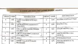
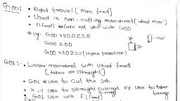
Mechanical Engineering Department, , CIM & Automation Lab (10ME78), , M10 CHUCK OPEN : Opens pneumatic or similar automatic chuck to allow for bar feed., M11 CHUCK CLOSE : Closes the chuck., M13 SPINDLE FORWARD, COOLANT ON : Sets spindle rotation forward and sets the coolant on,, both are performed by single code., M14 SPINDLE REVERSE, COOLANT ON : Sets the spindle rotation in reverse direction and sets the, coolant on., M30 PROGRAM END : Stops the spindle, turns the coolant off, terminates and resets the CNC program., M38 DOOR OPEN : Opens the door, waiting until the door is open., M39 DOOR CLOSE : Closes the door, waiting until the door is closed., PREPARATORY FUNCTION (G-Codes)., G00, , G CODES, Positioning (Rapid Tranverse), , G01, , Linear Interpolation (Feed), , G02, , Circular Interpolation (CW), , G03, G04, G20, , Circular Interpolation (CCW), Dwell, Inch Data Input, , G21, G28, G40, , Metric Data Input, Reference point return, Tool nose radius compensation cancel, , G41, , Tool nose radius compensation left, , G42, G50, G70, , Tool nose radius compensation right, Work coordinate change/ Max. Spindle speed setting, Finishing cycle, , G71, G72, , Multiple Turning Cycle in turning, Stock removal in facing, , G73, , Pattern repeating, , G74, , Peck drilling in Z axis, , G75, , Grooving in X axis, , G76, G90, , Thread cutting cycle, Cutting cycle A (Turning), , G94, G96, , Cutting cycle B (Facing), Constant surface speed control, , G97, G98, , Constant surface speed control cancel, Feed per minute, , G99, , Feed per revolution, , G00 FAST TRAVERSE, Description, PESIT, , Illustration, Page 9
Page 10 :
Mechanical Engineering Department, , CIM & Automation Lab (10ME78), , A rapid traverse instruction traverses the tool to, the target point at the maximum traverse rate. The, tool normally takes the shortest path from the, starting point to the destination point. The rapid, traverse is used for movements where no tool is in, engagement., , G01 LINEAR MOTION, Description, G01 traverses the tool along a linear path to the, given target point with the feed rate input as a, supplementary function. The feed rate determines, the speed with which the workpiece is machined., The choice of feed rate depends on the tool, the, material being machined, the required surface finish, and the drive rating and rigidity of the machine tool., , Illustration, , When giving the instructions G01, the coordinates, of the destination point can be expressed using, either absolute or incremental dimensions., Example : G01 X30 Z10 F100 S1000, Target point Feed Speed, , G04 DWELL, Description, A G04 causes the program to wait for a specified amount of time. The, time can be specified in seconds with the “X” or “U” prefixes or in, milliseconds with the “P” prefix. A G04 code can be inserted between, the two statements to make a sharp corner., , Illustration, G04 X1.5, G04 U1.5, G04 P1500, , G20 INCH DATA INPUT : A G20 causes position to be as being in imperial units. All the input values, are in inches. This can only be at the start of the main program., G21 METRIC DATA INPUT : A G21 causes positions to be interpreted as being in metric units. All the, input values are in mm. This can only be at the start of the main program., , G28 REFERENCE POINT RETURN, Description, A G28 causes a fast traverse to the specified position and then to the, machine datum., , PESIT, , Illustration, G28 X35 Z5, G28 U0 W0, , Page 10
Page 11 :
Mechanical Engineering Department, , CIM & Automation Lab (10ME78), , G40, G41, G42 TOOL NOSE RADIUS COMPENSATION, Description, On Modern CNC machines, special calculation functions or cutter radius compensation codes are, provided to allow a user to utilize part profile coordinates obtainable from the part drawing to, program a contouring motion. These are the G41 and G42 codes for tool radius compensation on, the left and right hand sides of a profile. A left or right compensation is based on the fact that the, tool is on left or right hand side when one goes along the part profile in the direction specified by, the contouring motion statements in the program. A G40 code is provided to cancel the cutter, radius compensation., G50 COORDINATE SETTING, Description, G50 enables tool nose radius compensation to the left of the programmed path. G50 has 2 uses., Coordinate setting block has “X”,”Z”,”U”, or “W” upon it. A maximum spindle speed block does, not have all these., G96 CONSTANT SURFACE SPEED, Description, The cutting speed during turning is the peripheral speed of the work. The peripheral speed is a, rotating work represents the peripheral path in a given unit time as shown in figure. The, peripheral speed or cutting speed is thus the fully stretched chip length produced in one time. The, cutting speeds vary in direct relation to the diameters, even if the number of revolutions per, minute is the same in all cases., The correct selection of the cutting speed for turning is very important,, Cutting speed too low : Time loss and low surface finish. With increasing cutting speed, the surface speed is improved., Cutting speed too high : High tool wear., G97 NORMAL SPINDLE SPEED, Description, G97 cancels constant surface speed. The spindle speed will not change until the next “S” value is, reached., G98 FEED PER MINUTE :, Description, This command coupled with the F word is used, to specify feed rate per minute. This can be in, either mm/min or inch/min. this is the default., , PESIT, , Illustration, , Page 11
Page 12 :
Mechanical Engineering Department, , CIM & Automation Lab (10ME78), , G99 FEED PER REVOLUTION, Description, This command coupled with the F word is used to, specify a feed rate per revolution. This can be in mm/rev, or inch/rev. the feed rates available in the machine, simulation are 0.01-200 mm/min. Recommended feed, rates are published by tool and cutter manufacturers,, along with recommended cutting speeds. If the feed rate, is expressed as mm/rev, a simple calculation can be used, to convert to mm/min., FEED, mm/min=FEED(mm/rev) X spindle speed(r.p.m), , Illustration, , PROGRAM BUILD-UP FOR CNC LATHE (FANUC), CNC program can be divided into 3 parts, Start-up, Body and End of the program., START-UP OF CNC PROGRAM, O1000, [BILLET X20 Z60, G21/G20 G98/G99 G40, G50 S1800, G28 U0 W0, M06 T0101, M03/M04 S1000, G00 X21 Z1, , EXPLANATION, O1000, , While writing a program on FANUC controller first line has to be started with, letter ‘O’ followed by four digit number which specifies the program name., , [BILLET X20 Z60, , This directive is used only for simulation purpose. It defines the work piece, dimensions as 60 mm long and 20 mm in diameter., G21 – code specifies that program is done in metric units., G20 - code specifies that program is done in imperial units, G98 – gives the unit of feed in mm/minute., G99 - gives the unit of feed in mm/revolution., G40 – Compensation cancel., Clamps the spindle speed at 1800 rpm., Makes the tool to go to home position. U & W are Secondary movements about, X and Z axis., Tool change, The first two digits specify the tool position in the turret and last two digits, denotes the tool offset number., M03- makes the spindle rotate in clockwise direction., M04 – makes the spindle rotate in counter-clockwise direction., S1000-Spindle rotates at 1000 rpm., G00 gives rapid position of the tool to a point X21 Z1 which is just above the, billet. This point is called as the tool entry point., , G21/G20 G98/G99 G40, , G50 S1800, G28 U0 W0, M06, T0101, M03/M04 S1000, G00 X21 Z1, , BODY OF THE PROGRAM: This is dealt operation wise in the succeeding pages., END OF THE PROGRAM:, G28 U0 W0, M05, M02/30, PESIT, , Page 12
Page 13 :
Mechanical Engineering Department, , CIM & Automation Lab (10ME78), , EXPLANATION, G28 U0 W0, , Makes the tool to go to home position. U & W are secondary, movements about X and Z axis., Stops the spindle rotation, M02 – Optional stop, M30 – Program stop and rewind., , M05, M02/30, , METAL CUTTING PARAMETERS FOR STARTURN LATHE, , BILLET MATERIAL : Aluminum, OPERATIONS, TURNING, GROOVING, THREADING, , SPEED,, rpm, 1000-1500, 600-800, 300-350, , FEED, mm/min, 45-55, 15-25, , DEPTH OF CUT,, mm, 0.5-1.0, 0.25-0.5, 0.03-0.04, , SIMPLE FACING, Write a manual part program for Simple Facing Operation for the component shown in figure, below., , DWG. NO. 1, BILLET SIZE : 22 x 60, PROGRAM NO : 1001, SL.NO, Operation, 1, , Simple, Facing, , Tool offset No., 1, , PESIT, , PLANNING AND OPERATIONS SHEET, MATERIAL : Aluminum, DWG NO : 1, Tool, Tool Tip, Tool, Tool, Spindle, Feed,, Holder, Station, Offset, Speed,, mm/min, No, No, rpm, SDJCR, DCMT, 1, 1, 1200, 45, 1212H11, 11T304, TOOL OFFSET SHEET, Compensations, mm, Toolnose, Standard Tool, Radius, mm, Number, X, Z, R, 0.4, 3, , Page 13
Page 16 :
Mechanical Engineering Department, , G01 Z-30 F45, G00 X22, G00 Z1, G01 X17, G01 Z-30 F45, G00 X22, G00 Z1, G01 X16, G01 Z-30 F45, G00 X22, G00 Z1, G01 X15, G01 Z-30 F45, G00 X22, G00 Z1, G01 X14, G01 Z-30 F45, G00 X22, G00 Z1, G28 U0 W0, M05, M30, , CIM & Automation Lab (10ME78), , -------- Going to home position, -------- Stop the spindle, -------- Program stop and rewind., , Note: Tool used External turning MTJNL 2020 K16 R0.8, , CIRCULAR INTERPOLATION – G02/G03, 1, , Data to be given, Rotation Direction, , 2, , End point position, , 3, , Distance from start, point to center, Radius of arc, , Command, G02, G03, Absolute, command, Incremental, command, , X,Z, U,W, I,K, R, , Meaning, Clockwise direction (CW), Counter clockwise direction, (CCW), End point position in the work, coordinate system, Distance from start point to end, point., Distance with direction from start, point to arc center., Radius of arc., , The end point of an arc is specified by address X,Z or U, W and is expressed as an absolute or, incremental value. For the incremental value, the coordinate of the endpoint which is viewed from the start, point of the arc is specified. The arc center is specified by addresses I and K for the X and Z axis. The, numerical value following I,J is always specified as an incremental value. I and K must be signed, according to the direction. The radius is specified with address R, if the circular path is greater than 180 0,, then R should be negative. For a lathe, because of the characteristics of the turning operation, the circular, motion can only be less than 1800., Clockwise and counter clockwise directions of rotations are distinguished on the basis of the rule, that when one looks from the positive direction of the axis perpendicular to the plane on which the circular, motion is performed, the motion is in clockwise and counter clockwise directions respectively. The, clockwise or counter clockwise direction varies in right or left hand coordinate systems as shown in figures, below :, , PESIT, , Page 16
Page 17 :
Mechanical Engineering Department, , CIM & Automation Lab (10ME78), , CONTOURING, Write a manual part program for Linear and Circular Contour Operation for the component shown, in figure below., , DWG. NO. 3, PLANNING AND OPERATIONS SHEET, MATERIAL : Aluminum, DWG NO : 3, Tool, Tool Tip, Tool, Tool, Spindle, Holder, Station, Offset, Speed,, No, No, rpm, Linear, SDJCR, DCMT, 1, 1, 1200, Interpolation 1212H11, 11T304, SDJCR, DCMT, Contouring, 1, 1, 1200, 1212H11, 11T304, , BILLET SIZE : 32 x 60, PROGRAM NO : 1003, SL.NO, Operation, , 1, 2, , Tool offset No., 1, , PESIT, , TOOL OFFSET SHEET, Compensations, mm, Toolnose, Radius, mm, X, Z, R, 0.4, , Feed,, mm/min, 45, 25, , Standard Tool, Number, 3, , Page 17
Page 18 :
Mechanical Engineering Department, , CIM & Automation Lab (10ME78), , (CNC program for Linear and circular interpolation, O1003, --------- Program Number 1003, [BILLET X32 Z60, --------- Defining Billet size dia : 32 length 60 mm, G21 G98, --------- Initial settings, G28 U0 W0, --------- Going to home position, M06 T0303, ---------- Selecting Tool No. 3 with offset No. 3, M03 S1200, ---------- Setting spindle speed at 1200 rpm, G00 X32 Z1, ---------- Tool moving to tool entry point X32 Z1 at, rapid traverse., G00 X5, G01 Z0 F30, G01 X10 Z-10 F45, G01 X10 Z-15, G02 X20 Z-25 R10 F25, ---------- Clockwise Interpolation – G02, G01 Z-30 F45, G03 X25 Z-37 R10 F25, ---------- Counter Clockwise Interpolation – G03, G01 Z-42 F45, X30 Z-47, Z-52, G28 U0 W0, -------- Going to home position, M05, -------- Stop the spindle, M30, -------- Program stop and rewind., Note: Tool used External turning MTJNL 2020 K16 R0.8, , G94 – FACING CYCLE, , Description, A G94 is a “Box Type” cutting cycle. This cycle, is used for stock removal either parallel or at an, angle to workpiece face. It is the equivalent of, rapid to Z position, feed to X position, feed to, start Z position, and rapid to start X position. If, the “R” value is specified tapering will be, performed. The sign of “R” depends on, direction of the taper. The initial rapid move will, be to the Z position plus “r” value. As canned, cycles are modal, to repeat the cycle for, removing further material only the value in the, axis to be moved needs to be changed., , PESIT, , Illustration, a)G94 X(U) Z(W) F, b) G94 X(U) Z(W) R- F, c) G94 X(U) Z(W) R+ F, Where X = diameter to which the movement is, being made., U= The incremental distance from the current tool, position to the required final diameter., Z= The Z axis coordinate to which the movement is, being made., W = The incremental distance from the current tool, position to the required position., R= The difference in incremental of the cut start, radius value and the cut finish radius value., Page 18
Page 19 :
Mechanical Engineering Department, , CIM & Automation Lab (10ME78), , BOX FACING, Write a manual part program for Box Facing Operation for the component shown in figure below., , DWG. NO. 4, PLANNING AND OPERATIONS SHEET, BILLET SIZE : 22 x 40, MATERIAL : Aluminum, PROGRAM NO : 1004, DWG NO : 4, SL.NO, Operation, Tool, Tool Tip, Tool, Tool, Spindle, Holder, Station, Offset, Speed,, No, No, rpm, 1, Box, SDJCR, DCMT, 1, 1, 1200, Facing, 1212H11, 11T304, Tool offset No., 1, , TOOL OFFSET SHEET, Compensations, mm, Toolnose, Radius, mm, X, Z, R, 0.4, , (CNC program for Facing cycle, O1004, [BILLET X22 Z40, G21 G98, G28 U0 W0, M06 T0303, M03 S1200, G00 X22 Z1, G94 X10 Z-0.5 F35, Z-1, Z-1.5, Z-2, Z-2.5, Z-3, Z-3.5, Z-4, Z-4.5, Z-5, G00 X22 Z-5, G94 X14 Z-5.5 F35, Z-6, Z-6.5, Z-7, Z-7.5, PESIT, , Feed,, mm/min, 45, , Standard Tool, Number, 3, , --------- Program Number 1004, --------- Defining Billet size dia : 22 length 40 mm, --------- Initial settings, --------- Going to home position, ---------- Selecting Tool No. 3 with offset No 3, ---------- Setting spindle speed at 1200 rpm, ---------- Tool moving to tool entry point X22 Z1, ----------- G94 Box Facing cycle, G94 code Syntax : G94 X Z F, , ----------- G94 Box Facing cycle, , Page 19
Page 21 :
Mechanical Engineering Department, , Z-1, Z-1.5, Z-2, Z-2.5, Z-3, Z-3.5, Z-4, Z-4.5, Z-5, Z-5.5, Z-6, Z-6.5, Z-7, Z-7.5, Z-8, Z-8.5, Z-9, Z-9.5, Z-10, G28 U0 W0, M06 T0101, M03 S1000, G00 X22 Z-10, G90 X22 Z-25 R0 F30, , CIM & Automation Lab (10ME78), , G94 code Syntax : G94 X Z F, , -------- Going to home position, -------- using Left Hand Tool, ------- Taper Facing Cycle – G94, , X22 R-0.5, X22 R-1, X22 R-1.5, X22 R-2, X22 R-2.5, X22 R-3, X22 R-3.5, X22 R-4, X22 R-4.5, X22 R-5, X22 R-5.5, X22 R-6, G28 U0 W0, M05, M30, , --------- Going to Home position., -------- Stop the spindle, -------- Program stop and rewind., , Note: Tool used External turning MTJNL 2020, K16 , R0.8, , G72 MULTIPLE FACING, Description, This multiple facing cycle is, used when the major direction, of cut is along the “X” axis., This cycle causes the profile to, be roughed out by facing., Control passes on to after the, last block of the profile. Two, G72 blocks are needed to, specify all the values., , PESIT, , Illustration, G72 W R, G72 P Q U W F S T, Where W – Depth of cut in Z axis, R – Escape of relief amount, P- The line number in the program marking the start of the finished, form required., Q - The line number in the program marking the end of the finished, form required., U – The amount and direction of the finishing allowance left in the X, axis, Page 21
Page 22 :
Mechanical Engineering Department, , CIM & Automation Lab (10ME78), , W – The amount and direction of the finishing allowance left in the Z, axis, F – Feed rate, S – Speed, T - Tool number, The values of F,S and T contained in the data blocks for the profiles, are ignored when G72 line is read., MULTIPLE FACING, Write a manual part program for Multiple Facing Operation for the component shown in figure, below., , DWG. NO. 6, PLANNING AND OPERATIONS SHEET, BILLET SIZE : 30 x 60, MATERIAL : Aluminum, PROGRAM NO : 1006, DWG NO : 6, SL.NO, Operation, Tool, Tool Tip, Tool, Tool, Spindle, Holder, Station, Offset, Speed,, No, No, rpm, 1, Multiple, SDJCR, DCMT, 1, 1, 1200, rough, 1212H11, 11T304, facing, 2, Finishing, SDJCR, DCMT, 2, 2, 1450, 1212H11, 11T302, Tool offset No., 1, 2, , TOOL OFFSET SHEET, Compensations, mm, Toolnose, Radius, mm, X, Z, R, 0.4, 0.2, , Feed,, mm/min, 45, 25, , Standard Tool, Number, 3, 3, , (CNC program for Multiple Facing cycle, O1006, --------- Program Number 1006, [BILLET X30 Z60, --------- Defining Billet size dia : 30 mm length 60 mm, G21 G98, --------- Initial settings, G28 U0 W0, --------- Going to home position, M06 T0303, ---------- Selecting Tool No. 3 with offset No 3, M03 S1200, ---------- Setting spindle speed at 1200 rpm, G00 X31 Z1, ---------- Tool moving to tool entry point X31 Z1, (MULTIPLE FACING CYCLE – G72, PESIT, , Page 22
Page 23 :
Mechanical Engineering Department, , CIM & Automation Lab (10ME78), , (Depth of cut for each pass W=0.5 mm, (Relief amount R = 0.5 mm, (P & Q – Beginning & end of cycles sequence Nos., (Allowances on X and Z axis = 0.1 mm respectively., (Feed rate F=35 mm/min., G72 W0.5 R0.5, G72 P10 Q20 U0.1 W0.1 F35, N10 G01 Z-52, X30, Z-47, X25 Z-42, Z-37, G02 X20 Z-30 R10 F25, G01 Z-25, G03 X10 Z-15 R10, G01 Z-10 F35, N20 X5 Z0, G20 U0 W0, M06 T0202, -------- Using Left Hand Finishing tool, M03 S1450, G00 X31 Z1, G70 P10 Q20 F25, --------- Finishing Cycle, G28 U0 W0, --------- Going to Home position., M05, -------- Stop the spindle, M30, -------- Program stop and rewind., Note: Tool 1:Tool used External turning MTJNL 2020 K16 R0.8, Tool 2: Tool used External turning MTJNL 2020 K16 R0.8, , G90 SINGLE TURNING CYCLE, This cycle can be used to produce either a parallel or tapered tool path. This cycle performs four distinct, moves with one line of information and it is equivalent of, Rapid to X position, Feed to Z position, Feed to start X position, Rapid to start Z position, Description, With the above command the cycle will execute, removing material to the required diameter and, length. To repeat this cycle to reduce the diameter, but maintain the same length, only the value to be, changed need to be programmed., , PESIT, , Illustration, G90 X(U) Z(W) F, Where X – Diameter to which the movement, is being made., U- The incremental distance from the current, tool position to the required final diameter, Z- The Z axis coordinate to which the, movement is being made., W- The incremental distance from the current, tool position to the required Z axis position, F- Feed, , Page 23
Page 25 :
Mechanical Engineering Department, , CIM & Automation Lab (10ME78), , Note: Tool used External turning MTJNL 2020 K16 R0.8, G90 TAPER TURNING, , Description, If an “R” value is specified in the command, format of G90 cycle, tapering will be performed., The sign of “R” will depend on the direction of, the taper. The initial rapid move will be to the X, position plus the “R” value., , Illustration, G90 X(U) Z(W) R F, Where X – Diameter to which the movement is, being made., U- The incremental distance from the current tool, position to the required final diameter, Z- The Z axis coordinate to which the movement is, being made., W- The incremental distance from the current tool, position to the required Z axis position, R- The difference in incremental of the cut start, radius value and the cut finish radius value., F- Feed, , TAPER TURNING, Write a manual part program for Taper Turning Operation for the component shown in figure, below., , DWG. NO. 8, , PESIT, , Page 25
Page 28 :
Mechanical Engineering Department, , CIM & Automation Lab (10ME78), , MULTIPLE TURNING, Write a manual part program for Multiple Turning Operation for the component shown in figure, below., , DWG. NO. 9, BILLET SIZE : 32 x 60, PROGRAM NO : 1009, SL.NO, Operation, 1, , Multiple, Rough, turning, Finishing, , 2, , Tool offset No., 1, 2, , PLANNING AND OPERATIONS SHEET, MATERIAL : Aluminum, DWG NO : 9, Tool, Tool Tip, Tool, Tool, Holder, Station No Offset No, SDJCR, 1212H11, , DCMT, 11T304, , 1, , 1, , Spindle, Speed,, rpm, 1200, , SDJCR, 1212H11, , DCMT, 11T302, , 2, , 2, , 1450, , TOOL OFFSET SHEET, Compensations, mm, Toolnose, Radius, mm, X, Z, R, 0.4, 0.2, , Feed,, mm/min, , 25, , 35, , Standard Tool, Number, 3, 3, , (CNC program for Multiple Turning, O1009, --------- Program Number 1009, [BILLET X32 Z60, --------- Defining Billet size dia : 32 length 60 mm, G21 G98, --------- Initial settings, G28 U0 W0, --------- Going to home position, M06 T0303, ---------- Selecting Tool No. 3 with offset No 3, M03 S1200, ---------- Setting spindle speed at 1200 rpm, G00 X32 Z1, ---------- Tool moving to tool entry point X32 Z1, (G71 MULTIPLE TURNING, (Depth of cut for each pass U=0.5 mm, (Relief amount R= 1.0 mm, (P and Q : Beginning and end of cycle sequence Nos., (Allowances on X(U) and Z(W) axis=0.1 mm respectively., (Feedrate= 35 mm/min., G71 U0.5 R1, G71 P10 Q20 U0.1 W0.1 F35, PESIT, , Page 28
Page 31 :
Mechanical Engineering Department, , CIM & Automation Lab (10ME78), , G00 X19 Z-34, G75 R1, ----------- GROOVING USING G75 CYCLE, G75 X16 W-2 P100 Q1500 F15, Z, X, (Relief amount, R=1.0 mm., (Depth of Groove, X= 2mm., (P- Peck increment along X axis 0.1 mm = 100 Microns., (Q – Stepping distance along Z axis 1.5 mm = 1500 Microns., G28 U0 W0, M05, M30, , 16, , -------- Going to home position, -------- Stop the spindle, -------- Program stop and rewind, , G76 MULTIPLE THREADING CYCLE, Description, This is a “Box type” cycle that is repeated a given, number of times. After the first pass subsequent, passes cut with one edge of the threading tool only, to reduce the load at the tool tip. This cycle, requires two distinct blocks of data. When the, cutting depth of one cycle becomes smaller than, the limit, the actual amount of cut is clamped at, the minimum cut depth., , Illustration, G76 P(m)(r)(a) Q(q1)(r1), G76 X(x) Z(z) P(p2) Q(q2) F, Where m – Repetitive count in finishing (1 to 99), r – Chamfering amount(0.01 to 9.91), a – Angle of tool tip(800,600,550,300,290 & 00), q1 – Minimum cutting depth., R1 – Finishing allowance., x – Finished depth of thread, z – End position of thread, p2 – Height of the thread as a radius value x 1000,, as the controller accepts this value in microns. Eg., 1.02 mm becomes P1020, q2 – Depth of first cut as a radius value X 1000,, value in microns, F- Lead or pitch of thread., , EXTERNAL MULTIPLE THREADING, Write a manual part program for External Threading operation for the component shown in figure, below., , DWG. NO. 11, PLANNING AND OPERATIONS SHEET, BILLET SIZE : 22 x 60, MATERIAL : Aluminum, PROGRAM NO : 1011, DWG NO : 11, SL.NO, Operation, Tool, Tool Tip, Tool, Tool, Spindle, Holder, Station, Offset, Speed,, No, No, rpm, 1, Multiple, SDJCR, DCMT, 1, 1, 1200, Rough, 1212H11, 11T304, PESIT, , Feed,, mm/min, 35, , Page 31
Page 33 :
Mechanical Engineering Department, , CIM & Automation Lab (10ME78), , G76 P031560 Q20 R0.15, ---------- MULTIPLE THREADING CYCLE., G76 X9.853 Z-19 P1073 Q30 F1.75, (03 – Number of passes for finishing operation, (15 - Chamfer amount or pull out angle, (60 – Angle of the thread, deg, (Q – Minimum cutting depth = 250 microns ( .25 mm), (R - Finishing allowances = 0.15 mm (X – Core diameter = 9.853 mm for M12, (Z – Length of thread=19 mm, (P - Height of thread = 1073 microns (1.073 mm), (Q – Depth of cut for first pass = 300 microns (0.3 mm), (F – Pitch of the thread = 1.75 mm, G28 U0 W0, -------- Going to home position, M05, -------- Stop the spindle, M30, -------- Program stop and rewind., , INTERNAL OPERATIONS, G74 END FACE PECK DRILLING, Description, This cycle is designed for deep hole drilling,, the drill entering the workpiece by a, predetermined amount then backing off by, another set amount to provide breaking and, allowing swarf to clear the drill flutes. The, cycle is commanded by two distinct lines of, data, , Illustration, G74 R(r1), G74 Z(W) Q(q) R(r2) F, Where r1 – Return amount, Z – Total depth(absolute), W – Total depth (Incremental), q – Depth of cut (incremental, unsigned), F- Feed rate, , PECK DRILLING, Write a manual part program for Peck drilling operation for the component shown in figure below., , DWG. NO. 12, BILLET SIZE : 32 x 60, PROGRAM NO : 1012, SL.NO, Operation, 1, , Center, Drill, Drilling, , 2, , Tool offset No., 6, PESIT, , PLANNING AND OPERATIONS SHEET, MATERIAL : Aluminum, DWG NO : 12, Tool, Tool Tip, Tool, Tool, Spindle, Holder, Station, Offset, Speed,, No, No, rpm, 6 mm, 6, 6, 1200, 12 mm, , 8, 8, TOOL OFFSET SHEET, Compensations, mm, Toolnose, Radius, mm, X, Z, R, -, , Feed,, mm/min, 20, , 800, , 20, , Standard Tool, Number, 6, Page 33
Page 38 :
Mechanical Engineering Department, , CIM & Automation Lab (10ME78), , PARTING OFF, Write a manual part program for turning and parting off operation through subprograms for the, component shown in figure below., , DWG. NO. 15, PLANNING AND OPERATIONS SHEET, BILLET SIZE : 22 x 60, MATERIAL : Aluminum, PROGRAM NO : 1015, DWG NO : 15, SL.NO, Operation Tool, Tool Tip Tool, Tool, Spindle, Holder, Station, Offset, Speed,, No, No, rpm, 1, Turning, SDJCR, DCMT, 1, 1, 1000, 1212H11, 11T304, 2, Grooving, HSS, 2 mm, 5, 5, 750, Tool offset No., 1, 5, , TOOL OFFSET SHEET, Compensations, mm, Toolnose, Radius, mm, X, Z, R, 0.4, -, , Feed,, mm/min, 45, 25, , Standard Tool, Number, 3, 8, , (CNC program for parting off using subprograms, O1015, --------- Program Number 1015, [BILLET X22 Z60, --------- Defining Billet size dia : 22 length 60 mm, G21, --------- Initial settings, G28 U0 W0, --------- Going to home position, M06 T0101, ---------- Using RH Roughing tool, M03 S1000, ---------- Setting spindle speed at 1200 rpm, G00 X22 Z0, ---------- Tool moving to tool entry point X22 Z0 at, PESIT, , Page 38
Page 40 :
Mechanical Engineering Department, , CIM & Automation Lab (10ME78), , COMPUTERISED NUMERICAL CONTROL MILLING, PART PROGRAMMING FUNDAMENTALS, 1. PART PROGRAMMING GEOMETRY, COORDINATE SYSTEM FOR A CNC MILL, Machining of a workpiece by an NC program requires a coordinate system to be applied to the machine, tool. As all machine tools have more than one slide, it is important that each slide is identified individually., There are three planes in which movement can take place., Longitudinal, Vertical, Transverse, Each plane is assigned a letter and is referred to as an axis, ie.,, Axis X, Axis Y, Axis Z, The three axes are identified by upper case X, Y and z and the direction of movement along each axis is, specified as either ‘+’ or ‘-‘. The Z axis is always parallel to the main spindle of the machine. The X axis is, always parallel to the work holding surface, and always at right angles to the z axis. The Y axis is at right, angles to both z and X axis. Figure shows the coordinate system for milling., , B. ZERO POINTS AND REFERENCE POINTS, MACHINE ZERO POINT (M): This is specified by the manufacturer of the machine. This is the x\zero, point for the coordinate systems and reference points in the machine. The machine zero point can be the, center of the table or a point along the edge of the traverse range as shown in figure the position of the, machine zero point generally varies from manufacture. The precise position of the machine zero point as, well as the axis direction must therefore be taken from the operating instructions provided for each, individual machine., , PESIT, , Page 40
Page 41 :
Mechanical Engineering Department, , CIM & Automation Lab (10ME78), , REFERENCE POINT (R): this point serves for calibrating and for controlling the measuring system of, the slides as tool traverses. The position of the reference point is accurately predetermined in every, traverse axis by the trip dogs and limit switches. Therefore, the reference point coordinates always have the, same, precisely known numerical value in relation to the machine zero point. After initiating the control, system, the reference point must always be approached from all axes to calibrate the traverse measuring, system. If current slide and tool position data should be lost in the control systems, for example, through an, electrical failure, the machine must again be positioned to the reference point to re-establish the proper, positioning values., WORKPIECE ZERO POINT(W) : This point determines the workpiece coordinate system in relation to, the machine zero point. The workpiece zero point is chosen by the programmer and input into the CNC, system when setting up the machine. The position of the workpiece zero point can be freely chosen by the, programmer within the workpicese envelope of the machine. It is however, advisable to place the, workpiece zero pijnt in such a manner that the dimensions in the workpice drawing can be conveniently, converted into coordinate values and orientation when clamping/ chucking, setting up and checking the, traverse measuring system can be effected easily. For milled parts, it is generally advisable to use an, extreme corner point as the “workpiece zero point”. Occasionally, the workpiece zero point is called the, “program zero point”, , CNC MILL PROGRAMMING, CNC PROGRAM BUILD-UP, Table1 shows the address letters according DIN 66025, Address Characters, Character, Meaning, A, Rotation about, X-axis, B, Rotation about, Y-axis, C, Rotation about, Z-axis, D&E, Rotation about, Additional-axis, F, Feed, G, Preparatory function, identifying the action to be executed, H, Unassigned, I, Interpolation parameter/ thread pitch parallel to x-axis, J, Thread pitch parallel to y-axis, K, Thread pitch parallel to Z-axis, L, Unassigned, M, Auxillary function, N, Block Number, O, Not used, P,Q,R, Thread movement parallel to X,Y & Z axes respectively, P&Q are also used as parameters in cycles, S, Spindle speed, T, Tool, U,V,W, Second movement parallel to X,Y,Z axes respectively, X, Movement I X-axis, Y, Movement in Y-axis, Z, Movement in Z-axis, All the NC words may not be used on every CNC machine. Using these words, as an example the, composition of a block is assembled as follows:, PESIT, , Page 41
Page 42 :
Mechanical Engineering Department, , N, , G, , X, , CIM & Automation Lab (10ME78), , Z, , F, , S, , T, , M, , ;, , PART PROGRAM FORMATS, The order in which these words appear in a block of instructions is called the format. Basically there are, two types of format:, Fixed Block Format, -Fixed sequential format, -Tab sequential format, Word Address Format, 1. FIXED BLOCK FORMAT:, a)Fixed Sequential Format : Every instruction contains all the words in the same sequence irrespective of, the words being the same as in the previous blocks. Hence the identifying address letter need not be, provided. For example, if some coordinate values(i.e., x, y and z coordinates) remain constant from one, block to next block these values have to be specified in the next block also. The data must be input in a, specified sequence and characters within each word must be of the same length., Example :, , N010 G00 X10 Y5 Z0 F60 S1200 EOB, N020 G01 X10 Y5 Z-0.5 F60 S800 EOB, , b)Tab Sequential Format : The words in each instruction / block are always provided in the same, sequence but each word is preceded by the TAB character. If instructions remain unchanged in succeeding, blocks, the instructions need not be repeated but TAB character must be punched. Here also, the, identifying letter address need not be employed., Example :, , N010 G00 X10 TAB Y5 TAB Z0 TAB F60 TAB S800 EOB, N020 G01 X20 TAB Z-0.5 EOB, , 2. WORD ADDRESS FORMAT: Each word is preceded and identified by its letter address. This format, enables instructions which remain unchanged from the preceding block, to be omitted from succeeding, blocks. This system speeds programming, and tape lengths are considerably reduced. This is the format, adopted by most CNC machine control units. Detailed format classification is provided by the control, system manufacturer., Example :, , N010 G00 X10 Y5 Z0 F60 S800 EOB, N020 G01 X20 Z-0.5 EOB, , MISCELLANEOUS AND PREPARATORY FUNCTIONS, , M Codes are instructions describing machine functions such as calling the tool, spindle rotation,, coolant on, door close/open etc., M00, M01, M02, M03, M04, M05, M06, M08, M09, M10, M11, M13, PESIT, , M CODES, Program stop, Optional stop, Program end, Spindle forward, Spindle reverse, Spindle stop, Tool change, Coolant on, Coolant off, Vice open, Vice close, Coolant, spindle fwd, Page 42
Page 43 :
Mechanical Engineering Department, , CIM & Automation Lab (10ME78), , M14, Coolant, spindle rev, M30, Program stop and rewind, M70, X mirror On, M71, Y mirror On, M80, X mirror off, M81, Y mirror off, M98, Subprogram call, M99, Subprogram exit, M00 PROGRAM STOP : By inserting M00 in a program, the cutting cycle is stopped after the block, containing M00 code. This facility is useful if an inspection check is necessary during an operation. The, cycle is then continued by a cycle start., M02 END OF PROGRAM : M02 halts program execution. The spindle is turned off and the tool moves, to the most positive position on the z-axis., M03 START SPINDLE : M03 instruction starts forward spindle motion. It requires a speed within the, range 100 to 3000rpm., Example: M03 S2200, M04 REVERSE SPINDLE : M04 instruction starts reverse spindle motion. It requires a speed within the, range 100 to 3000 rpm., Example: M04 S2200., M05 STOP SPINDLE : M05 instruction stops spindle rotation. It is good programming practice to issue, an M05 before a tool change, and at the end of program. However this will be done automatically should, you omit this instruction., M06 CHANGE TOOL : M06 instruction causes the FANUC to change to a different tool., Example: M06 t01, M08 COOLANT ON : M08 turns the coolant on, M09 COOLANT OFF : M09 turns the coolant off, M10/11 WORK CLAMP OPEN/CLOSE : M10 opens the work clamp, M11 closes the work clamp, M13 COOLANT, SPINDLE FORWARD : M13 turns the coolant on and starts reverse spindle motion., Example: M13 S1000, M14 COOLANT, SPINDLE REVERSE : M14 turns the coolant on and starts reverse spindle motion., Example: M14 S1000, M30 PROGRAM STOP AND REWIND : Stops the spindle. Turns the coolant off. Terminates and resets, the CNC program., M38/39 DOOR OPEN/CLOSE : M38 opens the door, M39 closes the door, M70 X MIRROR ON : M70 sets x axis mirroring about the current x axis position, M71 Y MIRROR ON : M71 sets Y-axis mirroring about the current Y axis position, M80 X MIRROR OFF : M80 disables X axis mirroring, M80 Y MIRROR OFF : M80 disables X-axis mirroring, , PESIT, , Page 43
Page 44 :
Mechanical Engineering Department, , CIM & Automation Lab (10ME78), , SUBPROGRAM CALL / EXIT- M98 / M99, Main program, A Program is divided into main program, and subprogram. Normally the CNC, operates according to the main program, but when a command calling a, subprogram is encountered in the main, program control is passed to the, subprogram. When a command indicting, to return to the main program is, encountered in the subprogram is, encountered in the subprogram, control, is returned to the main program. The first, block of program/subroutine must, contain a program number “o”, , Subprogram, When a program contains certain fixed sequences or, frequently repeated patterns, these sequences or patterns, may be entered into memory as a subprogram to simplify, programming. A subprogram can call a subprogram it is, regarded as a one-loop subprogram call., FORMAT:, O0001;, ………;, ………;, M98 POOOOOOO, Subprogarm Number, Number of repetitions, Subprogram call, ………., ………., M99, Subprogram exit, , Main Program, , Subprogram, , Subprogram, , O0001;, ……..;, ……..;, M98 P1000;, ……..;, ……..;, M30, , O1000;, ……..;, ……..;, M98 P2000;, ……..;, ……..;, M99, , O2000;, ……..;, ……..;, M98 P3000;, ……..;, ……..;, M99, , Ist Loop Nesting, , PESIT, , 2 nd Loop nesting, , Page 44
Page 46 :
Mechanical Engineering Department, , CIM & Automation Lab (10ME78), , G00 FAST TRAVERSE, Description, A G00 moves the tool to a certain position in the, work coordinate system with an absolute command, or to a position specified distance from the current, position with an incremental command at a rapid, traverse rate., , Illustration, Example: G00 X20 Y30 Z1, Here the tool is moved to, X20mm,, Y30mm, and, Z1mm, , G01 LINEAR MOTION, Description, This command actuates the linear interpolation mode. The, values of X,Y and z define the distance of tool travel which will, be conducted in absolute or incremental mode, according to the, current status of G90/G91. The feed rate is set to a cutting feed, speed commanded by F code and is modal data. The feed rate, commanded by the F code is measured along the tool path., , Illustration, G01 X(*x) Y(*y) Z(*z) F(*f), Example: G21, G01 X20 Y30 Z-1, , CIRCULAR INTERPOLATION (G02/G03), Sl no., 1, , Data to be given, Plane selection, , command, G17, G18, G19, , 2, , Direction of rotation, , 3, , End point G90 Mode, position, G91 Mode, Dist. From start point to, center, Arc radius, Feed rate, , 4, 5, , G02, G03, Two of the X,Y and Z axis, Twoz of the X,Y and Z axes, Two of the I,J and K axes, R, F, , Meaning, Specification of arc on XY, plane, Specification of arc on ZX, plane, Specification of arc on YZ, plane, Clockwise direction, Counter clock wise direction, End point position in the Work, Coordinate System, Distance from start point to, end point, Arc radius, Velocity along arc, , The view is from the positive direction of the z axis(Y axis or X axis) to the negative direction on XY, plane (ZX plane or YZ plane) in the right hand cartesian coordinate system. The following sketch shows, the CW and CCW directions in different planes, , G04 DWELL, Description, A G04 causes the program to wait for specified amount of time. The time can, be specified in seconds with the “X’ prefixes or in milliseconds with the “I”, prefix. One of the uses of this code is to get a sharp corner on the profile of, the workpiece in cutting feed. It is also used at the end of drilling cycle., During cutter motion, a deceleration at the end of the motion specified by, PESIT, , Illustration, G04 X1.5, G04 P1500, Page 46
Page 47 :
Mechanical Engineering Department, , CIM & Automation Lab (10ME78), , one statement and an acceleration at the start of the motion specifies by the, next statement are usually applied automatically by the controller., G20 IMPERIAL UNITS : A G20 causes position to be as being in imperial units. All the input values are, in inches. This can only be at the start of the main program., G21 METRIC UNITS : A G21 causes positions to be interpreted as being in metric units. All the input, values are in mm. This can only be at the start of the main program., , G28 GO TO REFERENCE POINT, Description, This command specifies automatic return to the reference point for the, specified axes. The co-ordinates defined in this command is an, intermediate co-ordinate and is commanded by absolute or incremental, value. The G28 block is used to position the tool at the intermediate, point of all specified axes at the rapid traverse speed, and then move to, the reference point at the rapid traverse rate. In general this command, is used for automatic tool changing. For safety reasons the cutter, radius compensation, and tool length compensation should be, cancelled before executing this command, , Illustration, G91 G28 X0 Y0Z0, makes the cutting tool to, move to datum point, directly., G91 G28 X0 Y0 Z20, makes the cutting tool to, go to datum point via the, intermediate point Z20., , G40, G41, G42 TOOL NOSE RADIUS COMPENSATION, Description, On Modern CNC machines, special calculation functions or cutter radius compensation codes are, provided to allow a user to utilize part profile coordinates obtainable from the part drawing to, program a contouring motion. These are the G41 and G42 codes for tool radius compensation on the, left and right hand sides of a profile. A left or right compensation is based on the fact that the tool is, on left or right hand side when one goes along the part profile in the direction specified by the, contouring motion statements in the program. A G40 code is provided to cancel the cutter radius, compensation., , G92 SET DATUM, Description, G92 sets the datum relative to the current, positions, , Illustration, Example: G00 X30 Y40, G90 X10 Y10, Makes the position that was X30 Y40 to become, X10 Y10, , G94 PER MINUTE FEED, Description, , PESIT, , Illustration, , Page 47
Page 48 :
Mechanical Engineering Department, , CIM & Automation Lab (10ME78), , With the per minute feed mode, tool feed rate per, minute is directly commanded by numerical value, after F. the “F” value specifies the feed rate in, millimeters, or inches per minute., , G95 PER REVOLUTION FEED, Description, This command coupled with the F word is used to, specify a federate per revolution. The feed rate is, changed whenever the spindle changes. This can be, in mm/rev to inch/rev. The feedrates available in the, DENFORD FANUC simulation are 0.01-200, mm/min., Recommended federates are published by tool and, cutter manufacturers, along with recommended, cutting speeds. If the feed rate is expressed as, mm/rev. a simple calculation can be used to convert, to mm/min., Feed, mm/min = feed(mm/rev) x spindle speed(rpm), , Illustration, , F= the displacement along the z axis per, revolution of the workpiece, Example G(% S1200, G01 X10.0 f0.3, This sets the feed rate to 360(1200*0.3), , CANNED CYCLES(G73, G74, G76, G80-89), A canned cycle simplifies the program using a single block with a G code to specify the machining, operations usually specified in several blocks. The following table give list of canned cycles., G code, , G74, G76, , Drilling, (-z direction), Intermittent, feed, Feed, Feed, , G80, G81, G82, , G73, , PESIT, , Canned cycles, Operation at the, Retraction, bottom of a hole, (+z direction), Rapid traverse, Feed, Rapid traverse, , Feed, , Dwell spindle CW, Oriented spindle, stop, -, , Feed, , Dwell, , Rapid traverse, , Rapid traverse, , Application, High speed peck, Drilling cycle, Left hand tapping cycle, Fine boring cycle, cancel, Drilling cycle spot, drilling cycle, Drilling cycle counter, drilling cycle, Page 48
Page 49 :
Mechanical Engineering Department, , G83, G84, G85, G86, G87, G88, G89, , Intermittent, feed, Feed, Feed, Feed, Feed, Feed, Feed, , CIM & Automation Lab (10ME78), , -, , Rapid traverse, , Peck drilling cycle, , Dwell spindle CCW, , Feed, Feed, Rapid traverse, Rapid traverse, Manual, Feed, , Tapping cycle, Boring cycle, Boring cycle, Back Boring cycle, Boring cycle, Boring cycle, , Spindle stop, Spindle CW, Dwell-spindle stop, -, , Generally, a canned cycle consists of a sequence of six operations as shown below, Operation, 1, 2, 3, 4, 5, 6, , Description, Positioning of axes x and Y(including also another axis), Rapid traverse up to point R, Hole machining, Operation at the bottom of a hole, Retraction to point R, Rapid traverse up to the initial point, , Positioning is performed on the XY plane and hole machining is performed on the Z axis. Positioning and, hole machining cannot be performed other than this plane and this axis combination. Canned cycle is, indifferent to the plane selection G command. These canned cycle operations, to be more strict, consists of, these three modes, each of which are specified in a particular modal G code. As shown below., Data format, , G90 absolute, , Return point level, , G91 Incremental, G98 Initial point level, , Drilling mode, , G99 R point level, G73,G74,G76, G80, G81,………..G89, , G91 INCREMENT MOVEMENT, Description, All future movement will be absolute until overridden by a G91, instruction. This is the default setting., , Illustration, Example: G90, G01 X30 Y0, The position becomes X30 Y0, , G91 INCREMENT MOVEMENT, Description, All future movement will be incremental until over-ridden by a, G90 instruction, , Illustration, Example: G90, G01 X15 Y0, G91, G01 X2 Y0, The position becomes X17 Y0, , G73 FAST PECK DRILLING CYCLE, Description, When drilling a deep hole, the drill should be retracted, occasionally to avoid congestion of chips between hole and the, drill. Since the Z-axis direction intermittent feed simplifies chip, disposal and permits a very small retraction value to be set in deep, hole drilling, efficient machining is performed. Retraction is, performed at the rapid traverse rate., Example:, PESIT, , Illustration, G73 X(*x) Y(*z) P(*p) Q(*q), R(*r) F(*f), Where, *x and *y = the next hole position, to drill at., *z= the depth of the hole, which is, the absolute distance in G90 mode, Page 49
Page 50 :
Mechanical Engineering Department, , M06 T03, M03 S1500, G90 G00 X10 Y10 Z10, G99 G73 X10 Y10 z-20 P500 Q0.5, R2 F50, G80, , CIM & Automation Lab (10ME78), , and the incremental coordinate, from R point in the G91 mode., *p= dwell time in sec., *q= the depth of cut for each peck, drill always a positive incremental, value., *r= the Z coordinates of the R, point (in G90 mode) or the, incremental Z coordinates from the, initial point to the R point(in G91, mode)., *f = feed, mm/min., , G74 LEFT HAND TAPPING CYCLE, Description, The cycle consists of a single block command. At the bottom of, the hole, the spindle rotates clockwise and left handed tapping is, performed., Note: During G74, the feed rate override is ignored and the cycle, does not stop until the end of the return operation. Even if a feed, hold is applied., Example:, M06 T01, M04 S200, G90 G00 X0 Y20 z10, G99 G74 X20 Y20 z-10 R5 F50, G80, , Illustration, G74 X(*x) Y(*y) Z(*z) R9*r), F(*f), Where,, *x *y= the next position to drill at., *z= the depth of the hole, which is, the absolute distance in G90 mode, and the incremental coordinate, from R point in the G91 mode., *r= The Z coordinates of the R, point in (g90 mode) or the, incremental Z coordinates from the, initial point to the R point in (G91, mode), *f= feed in mm/min, , G76 FINE BORING CYCLE, Description, This cycle is commanded in single block. Since a spindle oriented, stop is performed at the bottom of the hole and the spindle retracts, after shifting in the direction opposite to the cutter-direction, high, precision and efficient boring is performed without scratching the, workpiece., Example:, M06 T05, M03 S200, G90 G00 X0 Y20 Z10, G99 G76 X20 Y20 z-12 Q0.5 R-10 F50, G80, Note: the shift value is specified by Q. the Q value is always a, positive value. If a negative value is specified, the sign is ignored., The Q value is modal in the canned cycle., , Illustration, G76 X(*x) Y(*y) Z(*z) Q(*q), R(*r) F(*f), Where, *x,*y= the next position to drill at, *z= the depth of the hole, which is, the absolute distance in G90 mode, and the incremental coordinate, from R point in the G91 mode., *r= the z coordinate of the R, point(in G90 mode) or the, incremental z coordinates from, the initial point to the R point(in, G91 mode), *f= feed in mm/min, , G84 TAPPING CYCLE, PESIT, , Page 50
Page 51 :
Mechanical Engineering Department, , CIM & Automation Lab (10ME78), , Description, This cycle is commanded in single block. The spindle is reversed, at the bottom of the hole and the tapping cycle is performed., Example:, M06 T01, M03 S200, G90 G00 X0 Y20 Z10, G99 G84 X20 Y20 Z-10 R5 F200, G80, , Illustration, G84 X(*x) Y(*y) Z(*z) R(*r) F(*f), Where, *x,*y= the next position to drill at, *z= the depth of the hole, which is, the absolute distance in G90 mode, and the incremental coordinate from, R point in the G91 mode., *r= the z coordinate of the R, point(in G90 mode) or the, incremental z coordinates from the, initial point to the R point(in G91, mode), *f= feed in mm/min, , G87 BACK BORING CYCLE, Description, This cycle is commanded in single block. After the tool is, positioned along the X and Y axes, the spindle stops at the, orientation position. The spindle is then shifted in the direction, opposite to the tool and is positioned at the bottom of the, hole(point R) at the rapid traverse arte. At this position, the tool, returns only for the shift value and the spindle rotates clockwise., Machining is performed upto the point Z in the +z axis. At this, position, the spindle again stops at the orientation position and, shifts in the direction opposite to the tool and the tool is, withdrawn from the hole. After the tool returns to the initial point,, it returns only for the shift value. The spindle rotates clockwise, and the tool moves according to the command of the next block., Example:, M06 T01, M03 S1500, G00 X20 Y10 Z20, G98 X20 Y10 Z20, G98 G87 X20 Y10 Z20 Q4 R-27 F50, G80, , Illustration, G87 X9*x) Y(*y) Z(*z) Q(*q), R9*r) F(*f), Where *x *y= the next position to, drill at., *z= the depth of the hole which is, the absolute distance in G90 mode, and the incremental coordinate, from R point in the G91 mode, *q=the depth of cut for each peck, drill always a positive incremental, value, *r= the Z coordinates of the R, point(in G90 mode) or the, incremental Z coordinates from the, initial point to the R point(in G91, mode), , G170-G171 CIRCULAR POCKETING, Description, Using this cycle circular pocketing can be done. When the, tool has finished cutting, the tool retracts 1mm in Z axis., Moves to the center of the circular pocket at rapid traverse,, retracts again in the Z axis, then moves away to the datum, point. It requires two blocks., G170 R0 P0 Q3 X0 Y0 Z-6 I0 J0 K-24, G171 P75 S2000 R50 F150 B2500 J150, , PESIT, , Illustration, G170 r(*r1) P(*p1) Q(*q1) X(*x1), Y(*y1) Z(*z1) I(*i1) J(*j1) K(*k1), G171 P(*p2) S(*s2) R(*r2) F(*f2) B(*b2), J(*j2), Where, *r1= position of tool to start cycle ie., for, flat surface, *p1=0(roughing), = finishing, *q1= peck increment for each cut( always, a + value), *x1, *y1, *z1: coordinates of center of, circular pocket, *i1: finishing allowance for side, Page 51
Page 54 :
Mechanical Engineering Department, , G00 X0 Y0 Z5, , CIM & Automation Lab (10ME78), , M04- makes the spindle rotate in counter-clockwise direction, S1000-setting the spindle speed at 1000rpm, G00- gives rapid position of the tool to appoint X0 Y0 Z5 which is just above, the billet. This point is called tool entry point., , BODY OF THE PROGRAM : This is dealt operation wise in the succeeding pages., PROGRAM END, G91 G28 X0 Y0 Z0, M05, M30, , EXPLANATION, G91 G28 X0 Y0 Z0, M05, M02/M30, , Makes the tool to go to home position, Stops the spindle rotation, M02 Optional stop, M30 Program stop and rewind, PROGRAMMING EXAMPLES, LINEAR AND CIRCULAR INTERPOLATION, , Write a manual part program for Contouring operation for the component shown in figure below :, , DWG. NO. 1, PLANNING AND OPERATIONS SHEET, BILLET SIZE: 100X100X10, MATERIAL: Aluminum, PROGRAM NO:1001, DWGNO :1, SL.NO Operation, Tool type, Tool dia.,, Tool, Tool, Spindle, mm, station, length, speed, No., offset No, rpm, 1, Contouring, Slot cutter, 5, 1, 1, 2000, , Feed, mm/min, 30-50, , (Drawing No .1, O1001, (G01-Linear interpolation, (G02-Circular interpolation, (G03-circular interpolation anti-clockwise, [BILLET X100 Y100 Z10, ---- it defines the billet dimensions, [EDGEMOVE X-50 Y-50, ---- this directive sets up the required offset from the, program zero position to the middle of the billet. This, PESIT, , Page 54
Page 65 :
Mechanical Engineering Department, , 4., 5., 6., 7., 8., 9., 10., 11., 12., 13., 14., 15., 16., 17., 18., 19., 20., 21., 22., 23., 24., 25., 26., 27., 28., 29., 30., 31., 32., 33., 34., 35., 36., 37., 38., 39., 40., 41., 42., 43., 44., 45., 46., 47., 48., 49., 50., 51., 52., 53., 54., 55., PESIT, , CIM & Automation Lab (10ME78), , What is CAE?, What are different product activities?, What is a product cycle?, Block Diagram a conventional product cycle?, Block diagram of a product cycle with CAD/CAM?, What is Automation?, What are the benefits of CAD?, What is design process?, Block diagram for general design process?, Block diagram of a design process with CAD?, What is geometric modeling?, What is the basic classification of modeling?, What is engineering analysis?, What is design review and its evaluation?, What is automated drafting?, What is the use of database?, Block diagram of a database with CAD/CAM?, Advantages of CAD/CAM?, What are the basic computer hardware units?, What is the hardware configuration for a CAD system?, Block diagram of main frame based CAD hardware?, Block diagram of HOST satellite CAD system?, What is the design workstation?, What is a Graphics terminal?, What are the techniques to generate image on CRT?, Block diagram of CRT screen?, Classifications of a Graphics terminal?, Block diagram of DBRT?, Block diagram of DVST?, Block diagram Raster Scan terminal?, What are the different types of memory?, What is the input device? Identify the various input devices?, What is the output devices? Identify various output devices?, What is CPU? Explain its function?, What is a secondary storage devices?, What is a graphics software?, Ground rules for designing a graphics software?, Software configuration of a graphics system?, Basic modules and their functions in graphics software?, What is a primitive?, What is wire frame modeling?, Limitations of wire frame modeling, What is surface modeling?, Limitations of surface modeling?, What is solid modeling?, Limitations of solid modeling?, What is CSG or CREP in solid modeling, What are BREP, SREP, and PPI?, How does the data store in CSG, BREP?, Comparison between BREP & CSG, What is Transformation?, What is concatenation?, Page 65
Page 66 :
Mechanical Engineering Department, , CIM & Automation Lab (10ME78), , 56. What are the basic transformations available?, 57. What is clipping?, 58. Explain line-clipping algorithm?, 59. Explain Mid point subdivision algorithm?, 60. What is Viewing transformations?, 61. What is Windowing transformation?, 62. Define NC?, 63. What are the basic components of NC system?, 64. What is NC procedure?, 65. Discuss NC coordinate system?, 66. What is work piece Zero point?, 67. What is Machine zero point?, 68. What Home zero point?, 69. What is absolute positioning and incremental positioning/, 70. Discuss NC motion control systems?, 71. Applications of NC systems?, 72. Advantages and disadvantages of NC machine?, 73. What is NC part programming?, 74. What is manual part programming?, 75. What is computer assisted part programming?, 76. What are the various input mediums of an NC system?, 77. What does N Word stands for?, 78. What does G word stands for?, 79. What does M Word stands for?, 80. What does T word stands for?, 81. What is fixed sequential format?, 82. What is tab sequential format?, 83. What is word address format?, 84. What are part programmers job?, 85. Steps in computer assisted part programming?, 86. What is cutter offset computations?, 87. Functions of a Post Processor?, 88. What are the various NC part Programming languages?, 89. What are the various kinds of statements used in APT languages?, 90. What is geometric statement?, 91. What is a motion statement?, 92. What is PTP Statement?, 93. What is contouring motions?, 94. Define drive surface, part surface, chuck surface?, 95. Specify modifier words?, 96. What are post processor statements?, 97. What are auxiliary statements?, 98. What is Macro statement in APT?, 99. What is a plotter?, 100. Give some examples of High Level Language?, , PESIT, , Page 66
 Learn better on this topic