Notes of Second Year Civil, Civil & Highway Engineering Highway Engineering-2.pdf - Study Material
Page 1 :
Geometric Design of Highway, , , , , , , , , , , , Syllabus :, ‘C — recommendations,, 2.1 Various terms used in Highway : Camber : Definition, purpose, types as per IR, 2.2 Kerbs : Road margin road formation, right of way. :, — recommendations., , 2.3 Design speed and various factors affecting design speed as per IRC, 2.4 — Gradient : Definition, types as per IRC - Recommendations., , 2.5 — Sight distance (SSD) : Definition, types IRC - recommendations, simple numerical., 2.6 Curves : Necessity, types : Horizontal, vertical curves.., , 2.7 Widening of roads : types and problems, , 2.8 Super elevation : Definition, formula for calculating minimu, providing super elevation., 2.9 Standards cross sections of national highway in embankment and cutting., , im and maximum super elevation and method of, , , , 2.1 Geometrical Design of Highways, , It deals with the dimensions and layout of visible features of highway such as alignment, sight distance and, intersections. Geometric design of highways deal with following elements:, , 1. Cross section elements, , Sight distance considerations, Horizontal alignment details, Vertical alignment details, , yop wn, , Intersection elements, , 2.2 Important Highway Terms, , , , Set back, as s Set back, pos Road margin Road way Road margin distance, { i ——>, , ey, , , , Control line, , Building line, Building line, , Road land, Road land boundary, Control fines, , , , :, a8, i, E, i, ;, , |, |
Page 2 :
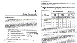
Highway Engineering (MSBTE) 2-2 Geometric Design of Highwa’, , Set back, distanc® Road margin Road way Road margin , Set back, Spoll bank) ieimence, , Berm, , , , , , , , , , Shoulder, —, , , , , Shoulder, —d, , , , , , , Side drain Side drain, , , , , , +¢—__________—_—— Over all width between control lines ——————*, , Fig. 2.2.2 C/S of Road in Cutting, , Important highway terms are as follow 2.2.1 Right of way, , important Highway Terms, , (a) Right of way {land is know i Y, , (MSBTE — W-12, S-13,, , , , , , , , , , , , , , , , , , , The land width is governed by the following factors, , , , Category of highway, , Topography and Vertical alignment, , Height of embankment or depth of cutting, Side slopes of embankment or depth of cutting, Drainage system and their size, , , , Sight distance consideration on curves, Reserve land for future widening is to be planned in, advance on future development and increase in the, traffic., , Table 2.2.1: Recommended land width for different class, of roads (metre), , NES Soe eeeN
Page 3 :
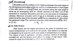
Major district, 2. 20 25| 18 15, 2 15., Oth tri, 3. coe 1S /15-25| 15 }15-20) 15 12, roads, 4.| Village roads | 12 |12-18] 10 |10-15] 9 9, , , , 2.2.2 Road Margin, (MSBTE - W-12, S-13), , , , The minimum shoulder width recommended by the, IRC is 2.5m., , 2.2.3 Road Way Width, , (MSBTE — S-13, W-10), , , , Table 2.2.2 Road way width of classes of road, , Geometric Design of, , (b) Two lane, , , , Other District Road, , , , , , , , , , , , (a) Single lane, , 3. | (a) Single lane TS 4.75, (b) Two lane 9.0 woken, , id, : Village roa ae “ah, , , , , , , , , , , , 2.2.4 Carriage Way, , Table 2.2.3 Width of Carriage way, , , , , , , , , , , , , , , , , , , , , , , , , , , , , , 1, | Single lane 3.75m, 2. _| Two lanes, without raised kerbs 7.0m, 3. | Two lanes, with raised kerbs 7.5m, 4, | Intermediate carriageway 5.5m, (except on important roads)., 5. | Multi-Lane Pavements 3.5m Per lane, 22.5 Shoulder —, , , , to, (MSBTE — W-10, W-11, S-13), , (eae;, , TO serve as an emergency lan for vehicle compelled, , , , , ‘tobe taken out of roadway or pavement., , as service lanes for, , ae
Page 4 :
Embankment, , (a) The height of the, embankment is over, 0.8m, , , , (b) The filling material subsoil, strata consists of heavy, , clay, , a, , , , (c) The height of the, embankment is more than, 3m and subject to, weathering, , Zz, , , , , , , , Cutting, Ordinary soil, , 1:1 to a4, 2, , , , (b, , Disintegrated rock or, clonglomerate, , tine, 2 4, , , , (c) Soft rock and shale, , ote a, 4 8, , , , {d) Medium rock, , io S, —i1to—1, 12 : 16, , , , , , (e) Hard rock, , , , , , Nearly vertical, , , , 2.2.7 Berms, , , , , , (MSBTE , W-10), , , , , , , , , , , 2.2.9 Borrow Pit, (MSBTE — S-12, S-13, S-15), , , , , , Q. Define : Borrow pit., , , , , , , , Maximum, 15, , , , , , , embankm, kneot Deadman, , Minimum 5m ”, , Borrow pit, , Fig : 2.2.3 Borrow pit., , , , , , , , , [Definition : eee eee er, material in, , , , , , pit is known as dead man,, , , , 2.2.10 Kerbs, (MSBTE -W-10, SH, $-12, W-12, $-13), , , , , , Fig. 2.2.4 Kerb, , Kerbs may be divided into following category based, on their functions., , (1) Low or mountable type kerb, , = This type of kerb encourage traffic to remain in, the through traffic lanes, yet allow the driver to, enter the shoulder area with little difficulty., , = The height of mountable type Kerb is 10cm above, the pavement edge., , )_Semi-barrier type kerb, , = Semi- barrier type Kerb is provided on periphery, of roadway where pedestrian traffic is high., , , , , , , , TechKnowledge
Page 5 :
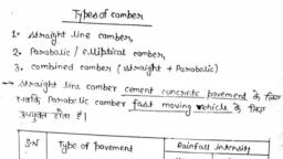
— This type of Kerb has 2 height of about 15 cm, above the pavement edge with a batter of 1:1 on, , the top 7.5 cm., This Kerb prevents encroachment of, , parking, , vehicles, , - But at emergency it is po:, Kerb with some difficulty., , ssible to drive over this, , (3) Barrier type kerb, , — Barrier type Kerb is provided in built-up areas, adjacent to foot paths with considerable, , pedestrain traffic., , The height of kerb stone is about 20 cm above the, pavement edge with a steep batter of 1.0 vertical, 0.25 horizontal., , 2.2.11 Formation Level, , , , Camber or Cross-slope, , 2.3, (MSBTE ~ W-18), , Geometric Desig, , , , R of High,, , layer, Subgrade soil thus avoig, is, , , , , , , pavement, the pavement., , t of the vehicles totravel along th, e, ber regulate the vehicles to the, , into the, deterioration of, 2. Tendency of mos', , center line, thus cam), , proper lanes, 3. To improve the architectural appearance of the my, , way., , 2.3.2 Types of Camber, (MSBTE - W-12, S-13, W-13, S-14, Sp), , , , , , , , , , Following are the types of cambers generally provided, , on road surface, 1, Straight or sloped camber, 2. Twostraight line camber, 3. Barrel camber, , (a) Parabolic barrel camber, , (b) Elliptical barrel camber, , 4, Composite camber, , 1. Straight line camber, , , , Fig. 2.3.1, , 2.3.1 Purpose of Camber, (MSBTE - S-10, W-10), , we To remove the rain water from the pavement surface, , , , re sleidy as possible to prevent the entry of water, , aia walt a, se, , , , Fig. 2.3.2, , WI, , ‘aac flat cross slope is provided as in cement, Pavements, straight line camber may be, , Provided as shown in Fig, 2.3.2
 Learn better on this topic