Notes of 3rd Year (6th SEM)Diploma, Structual Design & Soil Mechanics & Highway Engineering RCC CHAPTER 1.pdf - Study Material
Page 1 :
1, CHAPTER, , Introduction, -INSIDE THIS CHAPTER, 1.1. Plain Cement Concrete 1.2. Reinforced Cement, Concrete 1.3. Materials Used in R.C.C., , 1.4. Reinforcing Material 1.5. Types of Steel Reinforcement.1.6.Charaocteristic Strength of Steel 1.7. Types, , of Loads on R.C.C. Structures 1.8. Design Philosophies, , 1.1., , PLAIN CEMENT CONCRETE, , Plain Cement Concerete is a hardened mass obtained from a mixture of cement, sand, gravel and, , water in definite proportions. These ingredients are mixed together to form a plastic mass which is, , poured into desired shape moulds called as forms. This plastic mass hardens on setting and we get plain, cement concrete. The hardening of this mixture is caused by a chemical reaction between cement, and water., , Plain cement concrete has good compressive strength but very little tensile strength, thus limiting, its use in construction. Plain concrete is used where good compressive strength and weight are the main, , requirements and tensile stresses are very low., , 1.2. REINFORCED CEMENT CONCRETE, Plain cement concrete has very low tensile strength. To improve the tensile strength of concrete, some sort of reinforcement is needed which can take up the tensile stresses developed in the structure., most common type of reinforcement is in the form of steel bars which are quite strong in tension., The reinforcing steel is placed in the forms and fresh concrete is poured around it. This solidified, , composite mass is called as Reinforced cement concrete and is abbreviated as R.C.C. Thus, Reinforced, cement concrete is a composite material which is made up of concrete and steel reinforcement. The steel, reinforcement, generallyinthe form of steel bars, are placed in the tensile zone of the structure and, , take up the tensile stresses. R.C.C. is a versatile constYuction material which is strong in compression as
Page 2 :
Relnforced Cement Concrete Design, well as tension., , The, , use, , not only, , concrete, of reinforcement in, , imcreases its, , strength but also, , stresses., , preventing the temperature and shrinkage, and concrete in, The composite action of steel, , a, , reinforced, , conerete section is, , helDs, , n, , Reinforced, , in constriction, , some, , R.C.C. consists, , of which are listed below, , 1. Buildings, 3. Water Tanks, 4. Road and Rail Bridges, 5. Chimneys and Towers, , 12.2. Acvantages and Disadvantages of R.C.C., , Advantages, , (vii), , Reinforced cement concrete has following, 1. Strength: R.C.C. has very good, , advantages over, strength in tension as, , 6., , 7., 8., 9., , other construction materials:, well as compression., , Durability: R.C.C. structures are durable if designed and laid properly. They, 100years, Mouldability: R.C.C. sections can be given any shape easily by properly, formwork. Thus, it is, , 5., , The steel, , more, , suitable for architectural, , reinforcement imparts ductility, , requirements., , designing, , material. The, used., , strength, , of, , an, , R.C.C. section, , depends, , The water used for, , mixing should be free from all harmful organic substances., The aggregate should be hard, durable and, properly graded. For most R.C.C. works., 12e of aggregate is suitable., The cement used for, and not by volume., , mentioned advantages, R.C.C., R.CC. structures are heavier than structures ofhas, , 2. R.C.C. needs lot, of, space and skilled, , formwork, centering, , labour., , following disadvantages:, other, , materials like steel, wood and, glass, and, shuttering to be fixed, thus require lot or c, , s, , work, , should, , be of, , good quality, , TABLE 1.1. Grades of Concrete, , Group, , Designation, , Ordinary, , M10, , Concrete, , M15, , M20, , and, , measured by weight only., , (TCT bit 2 Pn -16), , Characteristie Compressive Strength, Sa Nham), , 20, , M25, , 25, , M30, , 50, , Standard, , M35, , 35, , Concrete, , M40, M45, , 5, , earthquakes, , the above, , R.C.C., , 20 mm, , Concrete is graded or designated on the basis of its compressive strength. As per IS456:2000., concrete is graded into fifteen types as given in the Table 1.1. (Table 2. IS456:2000), , the, , to the, , Disadvantages:, 1., , can last up to, , RC.C. structures., Economy: RC.C.is cheaper as compared to steel, concrete. There is an overall, andprestressed, economy by using R.C.C. because its maintenance cost is, low., Transportation: The raw materials which are required for R.C.C., water and steel are, easily available and can be transported i.e., cement, sand aggregate,, easily. Nowadays Ready MIX, Concrete (RMC) is used for faster and, better construction. (RMC is the, concrete which 1s, manufactured in the factory and, transported to the site in green or plastic, Fire Resistance:, R.C.C., structures are more fire resistant than otherstate)., construction materials like steel, commonly useu, and wood., Permeability: R.C.C. is almost, impermeable to moisture., Seismic Resistance:, Properly designed RC.C. structures are, extremely resistant to, , Despite, , reinforcing, , reinforcement, , The properties of concrete, depends upon the proportions and type of its ingredients. A, properly, designed concrete mix is very durable. A good concrete, mix should satisfy the, following requirements, (i) The concrete should be mixed, thoroughly to from a homogeneous mix., (ii) Concrete should be, compacted properly to prevent it from being porous., (ii) Sufficient curing of concrete is required for, developing full strength., iv) The water cement ratio should be apropriate,, considering the strength and workability criteria., (v) The concrete mix should be designed, properly and should have all the ingredients in right, , (vi), (vi), , 7. Bunkers and Silos, , 4. Ductility:, , of concrete and, , proportions., , 6. Retaining Walls, , 3., , immediately, , 1.3.1. Concrete, , 2. Flyoverss, , 2., , strength. Thus, R.C.C. structures can't be used, , MATERIALS USED IN R.C.C., , upon the kind of concrete and, , 1.2.1. Uses of Reinforced Concrete, uses, , Concrete takes time to attain its, after construction unlike steel full, , structures., , 1.3., , concrete., )The bond betweensteel and, bars embedded in the concrete., steel, of, () Prevention of corrosion, of both concrete and steel., (ii) Practically equal thermal expansion, , concrete has innumerable, , 3., , dependent on the, , following important factors:, , cement, , Introduction, , M50, M55, , 0, , M60, , 60, , M65, , 65, , High, Strength, , M70, , Concrete, , M75, , M80, , 0, 75, 80
Page 3 :
19h AlamA, , Reintorced Cement Concrete Design, number. The letter "M' refers to the, of concrete in N/mm*., , Introduction, mix, , M followed by, expressed by letter, strength, characteristic compressive, the, and the number represents, 150 mm size cube at 28 days., for, is determined, The specitied characteristic strength, re, is defined as that strength below which not moro, The characteristic compressive strength ofconcrete, use are, their, The various grades of concrete, per, as, than 5 perent of the testresults are expected to fall., Not tae, MI, Fr, Nomin Min - MSS, Tisted beloW: P e c, M20, l . For R.C.C. work not lower than, above, V2. For post tensioning works M35 and, M40 and above, cne, concrete, a, , Concrete grades, , are, , -, , OTdinn e, Stodnl, , -, , For pretensioned prestressed, , $., , M20, vjs MS, , Concrete of grades lower than M20 may be used for plain concrete works, lean concrete, simple, foundations, masonry walls and other, , works., , simple constructions, , 1.3.1.1. Concrete Making Materials, , Conr' K setiCon, , (i) Rapid Hardening Portland, Cement, , Rapid hardening cement is finely ground, and has more percentage of tricalcium silicate and, aluroihgte, which results in rapid hardening, and quick, development of the strengun. This type of aicaledum, used in places, cement is, construction works, where, to be done,, faster, that the, fom_work, can, be removed, early. For example, in road works etc. Rapid hardening portland cement should, confirm to IS, are, , so, , 8041:1990., , (iii), , Low Heat Portland Cement, i, Low heat portland cement has, lower, silicate and dicalcium aluminate,, which results in slow hydration of cementpercentage of tricalcium, and, Iow heat of hydration is evolved. This type of, cement is used in mass concrete works, such, as gravity dams, retaining wall. bridge abutments etc.., where large amount of concrete may result in very high heat of hydration. High heat of hydration can, lead to severe cracking of the concrete. This cement should confirm to IS, 12600:1989., , hence, , (iv) Portland Slag Cement, , (1) Cement, , concrete which, shows binding, properties after, which, hardened mass, , Cement is the only chemically active ingredient of, reacting with water. It consist of silicates and aluminates of, , after, calcium, form a, mixing with water. This type of cement is also known as hydraulic cement. There are many types of, , Blast furnace slag is the waste product of Pig Iron industry. This slag is mixed with the cement, clinker amd ground properly to obtain portland slag cement. The slag imparts high resistance against, Sulphate attack to the cement. Therefore, it is widely used in places where chances of sulphate attack, , cements available in market. some of which are explained beiow:, , are there, such as under soil construction works (subjected to ground water exposure) and near the, industries emitting waste containing sulphates. It should confim to IS 455:1989., , (i) Ordinary Portland Cement, , (v) Sulphate Resisting Cement, , Ordinary portland cement (OPC) is commonly used in construction. The Bureau of Indian standard, OPC in three grades. This ciassification is based, on the compressive strength of, cubes. The face area of these cubes shall be 50, The cube is made of I part of cement, mortar, to 3, sand by weight. with a specified water cement ratio. The grades of OPC cement, as per this classification are, following:, has, , classified, sand, parts of standard, , cement, , cm., , i ) 33 grade, ii) 43 grade, , Hii) 53 grade., , Here the grade number indicates the minimum compressive strength of cement-sand mortar cubes in, N/mm at 28 days., It, , is, , preferable, , to, , measure cement in terms of its, , changes, , with the environment conditions. In, volume is equal to 34.5 litres. The maximum, , as per IS 4S6: 2000, 28, , In addition to above,, , day copressive, Type, B, C, D, F, , our, , weight,, country, cement, , not volume, , is, , because volume of cement, , supplied, , in, , bags of 50 kg and s, , cement content used for R.C.C. construction is 450 kg/m, ISCl-82 u2 P4, BIS has further classified cement into following types depending on, , tne, , strength., , Compressive Strength (N/mm or MPa), 32.5 37.5, , 37.5 42.5, 42.5, 47.5, 52.5, 57.5, 62.5, , 47.5, 52.5, 57.5, 62.5, 67.5, , ISLTbe S, (Hae 26), , Sulphate resisting cement has very low percentage of tricalcium aluminate and is ground much, , finer, than ordinary portuland cement. Thiscement has very highsulphate resistance and is widely used, for under soil/ground water construction works., (vi) Portland Pozzolana Cement, , Porland Pozzolana cement contain pozzolanic material, clay or flyash. This cement is, obtained by grinding pozzolana and cement clinker together. The pozzolana have no cementitious, free lime they producea compound having cemertitious, properues themselves but when they combine with, as, cement is cheaper and has a lower rate of development of strength, Pozzolana, Porland, properties., all general construction, for, now, used, is, cement, Pozzolana, widely, being, compared to OPC. Portland, , like burmt, , works., (vi) White Cement, while manufacturing cement,, is obtained by controlling the percentage of iron oxide, This cement is manufactured by heatingon, materials., raw, by using China clay, chalk and lime stone as coal so that there are no chances of contamination with, oil fuel in place of, a very low flame by using, of desired colour., cement inorder to obtain cement, Coloured, pigments a r e added to the white, coal ash., This, , cement, , This cement is used for all aestheticworks., (2) Aggregate, , material or chemically inactive, of aggregates. Aggregates are inert, are, The bulk of concrete is made up, less than 4.75 mm size, broken bricks, gravel ete. Aggregate,, Coarse, material like crushed rock, sand,, coarse aggregate., as, known, 4.75 m m size are, and which are more than, known as fine aggregate, the coarseaggregate and, acts as a filler between, concrete and fine aggregate, to, durable and well, aggregate gives strength, should be hard, strong,, The, mix., aggregate, c, o, n, c, r, e, t, e, to the, read from any, be, provides workability, More about aggregate can, and dense mass of concrete., to form a compact, graded, book on "Conrete Technology"., , h a l isAih, , Setti, , a Com
Page 4 :
Reinforced Cement Concrete Desion, , Introduction, The, , workability to c o s, also for provid1ng, cement and, of, amount, reaction, and tree trom injurious, of, for chemical, should be clean, Water is rquired, oi., concrete, 0, gives, or steel. BIS 456:2000, of, concrete, curing, and, harm, I w a e r used for miving, which can, , following, , (3) Water, , or oxher, a a k a i e s , saits, , permixsible kimits, , of, , chemical, , Permissible, , gives the workability requirements for various types, Workability Requirements for Different Works, , TABLE 12., , Placing Conditions, , substance., , in, impurities present, , Table 1.2, , Degree of Workability, , Binding concrete, shallow, , water., , in Water, Limits of impurities, , Very, , 1SC:, , 2., , Lightly reinforced beams. slabs. walls, , PaS, , s000 mg, , Chiorndes (C, , plain, , 400 and 50, , Salphanes (S0, , coacrete, , mgl, , works, , for RCC works, , The fodiow i, , concrete, , depend, , properties, , and, , proportions of, , its, , ingredients., , 1) Compressive Strength, The coressive sengh of coree is dtermined by the cube test. The characteristic, s t aesive strength of 15 cm cubes at 28 days in N/mm', below, ngh cf comcree, , compressive, , isfned, , wic a ore han 3t o f * N u s ar expected to fall. It is represented asf. Cube samples are, k n a he banhing pianm a i r i t I iays The compressive and tensile strnegth in bending, , animaásins d eliastiiy of onee an becoerelated th the characteristic compressive strength. So, Te c se Sen of conreseis mprt ication of its overall strength., The seng d ccuree s y, faai by e waaer cemeni ratio. Higher the water cement, As pr Ams ka,, S, S, eocompressive strength of concrete is inversely, E, a-emen o . proviied e i s d workable consistency. K - T2o, The waner comEm n 2 i, iso ñecs e, worizblity of the mix. Therefore, an optimu, w CEI, uirei v ge 2 mi of desirei sorizbility and marimum, strength. The reduced, w ETeT, S E i s I enitamcemet of density and impermeability of concrete and reducio, , 2ariaility, The warkairg, sf cancee s dineds e ease by wtich it can be mixed,, Smsted A varkacie cmcee siaouid, placed, compacted anu, sor bieed or, segepae., , Woriability depends upon the fouo, , 3 Stape od ggregne, , e, , 4, , mesued y, , snssmeer tes, , 3Compacion facr es, , te, , 75 mm, , Raio of fise, , folowing tests, , to coarse, , aggrege, , 5 0 mm - 100 mm, , Medium, , walls., , 100 mm, , High, Pa- 20., , I50 mm, , Workability to be determined by Je Bu, determinant of flow, , Very high, , (3) Durability b e 5 ISC, upon the, , rtmoran properties of coacrete which are used in the design:, , Tte orkaiit a e, , Heavily reinforced slabs, beams,, columns pumped concrete, , 5. Tremite concrete, , 13.12 Properties of Concrete, The properties of, , 3., , 4 . Trench fill, in situ piling, , 2000 mgl, , Suspended solis, , 25 mm, , Low, , footing. mass concreting, , 200 mg, 2000 for, , Workability to be determined b y S -?, compaction factor (0.75-0.80), , columns floors. lining of canal, strip, , Orgamic, laorganic, , ISC-Cl*, , Stump, , low, , Seeuons. pavements using paveers, , Permissible Limits, , of works., , (Ta bl3 -Paru ? Fot, 7, , The concrete should be durable to the environment it is exposed to. during its life. The various types of, 456:2000 which specifies the maimum water cement, exposure conditions are listed in Table 5 of IS, conditions of exposures and is given in Table 1.3., different, under, content, cement, minimum, ratio and, Minimum Grade, TABLE 1.3. Minimum Cement Content, Maximum Water Cement Ratio and, mm Aggregates, 20, Normal, with, Different, Weight, Exposures, of Concrete for, Reinforced Cement Concrete, Minimum Cement, , Maximum free, , Minimum grade, , Content kg/m, , water cement ratio, , of concrete, , Mild, , 300, , 0.55, , M20, , Moderate, , 300, , 0.50, , M25, , 320, , M30, , Severe, , 0.45, , 0.45, , M35, , Very severe, , 340, 360, , 0.40, , M40, , Extreme, , Exposure, , NO., , 5., , is its permeability, The main characteristic of durability, carbondioxide, chloride, sulphate etc., , (4), , Tensile Strength, , S, , C-12, , to, , the, , ingress of, , water,, , oxygen., , 1, , the characteristic compressive, of concrete can be correlated with, As writen earlier, the tensile strength, used in the design., be, can, which, the following correlation, concrete. IS 456 gives, , strength of, , S =0.7 fa, (S) Modulus ofElasticity I5 Cl 6 2-3 1 also be, expressed in, static modulus of elasticíty can, written as follows:, strength and may be, , The short, , compressive, , terms, , of the, , characteristic, , term, , E S00Fa, , Ec510Ce, , Per 2S, , ***
Page 5 :
Reinforced Cement oncrete Design, , Introduction, , TABLE 1.4. Various Types of Environment Exposure Conditions, strain., , (6) Poisson's Ratio, the ratio, , ratio, , Poisson's, varies, , from, , is defined as, t, for c o n c r e t e ., , the longitudinal, strain to, all design, , of lateral, taken, , can, , The, , be, , calculation, , Creep is, , caused under, , is, loading. It, , Environment, Mild, , seen, , when, , that, , keeps increasing with time dependent,, loading. strain, stress and is, caused dueto sustained, factors, , sustained, , subjected, concrete is, This strain, , increase.in the load., lt aepenas upon, as creep., called, is, , any., time, even without, , Exposure conditions, , the, , 2., , Moderate, , which iis, following, ng, , No SvenRoio, , at, , NO Coh, , The surface of, , of loading, (c) Duration, values of creep, of actual data. following, absence, In the, , coefficient, , for design, may bbe taken, , TSC, , considerations, , Creep Coefficient, , Age at Loading, , 8, , CL 6-25, , 1.6, , days, , 1.1, , year, , ISC Pe -16, (:2.4., , (8) Shrinkage, , concrete., Inthe absence of any data, IS code 456 recommends a value of 0.003 mm/m as the ultimate shrinkage, strainand it can be used for all design calculations., , Entraard Air), per 456. if freezing and thawing conditions exists, then durability of concrete, should be, enhanced by adding suitable air entraining admixtures. IS 456:2000 recommends the percentage or, (9), , Frezing ISand Thawing (, As, , entrained air for nominal maximum size, , of aggregate as follows:, , Nominal maximum, , Entrained, , size of aggregate, , das, c h n k, , 28ays, , is, , yèer, , The air entrainment results, , taken care while, , designing mix., , in, , hwwmdhn SO Ia,, , Fo, , ISC, , air (%), , 20 mm, , 40mm, reduction in the, , (1), , exposed to sulphate attack such as in coastal, , resisting cement. Table 4 of IS 456 (Table, , maximum, , free, sulphate attack., , environment, should be made from, required, , concrete., , Nominal Mix Concrete, , and water are adopted is called as, A concrete mix in which the proportions of cement, aggregate, desired, the, will, strength and properties. For example,, give, nominal mix. It is not necessary that such a mix, not used for grades higher than M20. It is, is, mix, Nominal, 1:2:4., is, MI5, of, nominal mix proportions, used for ordinary concrete works only., for nominal mix concrete shall, As per IS 456:2000 (Clause 9.3.1). The proportional of materials, 1.5., Table, the, be in accordance with, following, , TABLE 1.5. Proportions for Nominal Mix Concrete, Total, , quantity of dry ggregates, , to, by mass per 50 kgof cement, individual, , be taken as the sum of the, masses of fine and coarse aggregates, , recommendations regarding the type ofsuipia, water/cement ratio and minimumgives, cement content, ceme, etc.,, 14), , (1), , Grade, , D, , at, , places subjecic, , 20., , Nominal mix concrete, , of concrete, , (10) Sulphate Attack, Concrete, , aggressive chemicals., , massesO, , of the concrete mix and, hence it 1s to, , in, , Concrete surfaces in tidal zone. Concrete in direct contact with, , (2) Design mix, , 4t1, strength, , and, , attain the desired strength, The determination of the proportions of cement, aggregates and water to, mix, concrete, as, is, called, proportioning., and properties such as workability, durability etc.,, IS 456:2000 (Clause 9):, The design of concrete mix is classified into following two types by, , c2-82-23, , - 18, , 5t1, , wetting, , 1.3.1.3. Concrete Mix Proportioning, , causes, , by, , ), , Tid, , strain in, Concrete shows shrinkage, of moisture evaporation. Shrinkage also, to, The shrinkage strain depends mainly upon the amount of water present at the time of casting, , due loss, , exposed to severe rain., , alternate, , Concrete exposed to coastal environment, s e a water spray.,, wateer. Concrete, fumes, s e v e r e freezing. Concrete immersed in s e a, contact or under aggressive soil or groundwater., , Extreme, , 2$, , Pant-16, , 2.2, , 7 days, , Coa, , .e, , concrete, , drying, sometimes freezing whilst wet or severe condensation., corroSive, , Very Severe, , 4., , the concrete aheltered from saturated salt air i n c o a t, , coastal areas., , A, , 3., , loading, , (not coastal areas), whilst |, The surface of concrete, sheltered from severe rain o r freezing, and condensation) concrete, wety The concrete surface (exposed to rain, or groundShu, water, concrete in contact or under soil, , environment, , (continuously_under, water.The surface of, , (a) Stress level, , (b) Age, , Tab3, , The surface of the concrete is protected against weather or aggressive, , No s e l, , No Sev na, to, , sustained, , S. No., , purposes., , as 0.2 for, , 0.1 to 0.3, , (7) Creep, , T, , at, Poisson's, s rratio, , Proportion of fine, aggregate to, , coarse aggregate, , TSC PaL 23c1-, , Maximum quantity, of water per 50 kg, of cement (), , (by massS), 60, 45, , M5, , 800, , Generally 1:2 but, , M7.5, , 625, , may very from, , M10, , 480, , 34, , M, , 330, , 32, , M20, , 250, , 30
Page 6 :
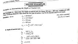
Reinforced, , Cement Concrete, , Design, , TABLE 1.7. Minimum Cement Coment, Maximum Water-Cement Ratio and Minimum, Grade of Concrete for Different Exposures with Normal Weight, Aggregates of 20 mm Nominal Maximum Size, , ofc o n c r e t e to, is s c e n that 'miv, , pet, , (2) Design, , Concrete, , Mix, , obtained, concete, , The, , by poperty, , strength, , the, of desired, produce, design' not only, concree, , is preferred, , IS, , over a, , 10262-2009, , concrete, , nominal, , is, , the, , determining, , and pmperties, , mix, , of desired, , mixes., , called, , as, , f, , Design, , the, , Mix, , It, , one., , A, , design mix, , concrete, , SI. Exposure, , but also an, recommendations, , 'concrete mix design', , which, , gives, , for the design, is required, , of a, , concrete, , for, , design, , Cement, , of, , Following, , (ir), , Maximum, , (, , water cement, , ratio by weight, , () Type of aggregate, , Minimum, , cement, , Mild, , (i) Moderate, , 1., , Type, , of, step wIse procedure for design, Caiculate the mean target strength, , (i), , concrete, , f), , mix is, , as, , follows:, , from the desired characteristic, , strength G, 2., , I f a +165%, where, , is the standard deviation which depends upon the quality control. In the absence of any, , specific data. Table 8, , of code IS 456:2000, , or, , Grade o concrete, , L, , Table, , Assumed standard deviation, , M10, , (7), , (8), , Grade of, , Concrete, , kg/m, (6), , (5), , 300, , 0.55, , M 20, , M15, , 300, , M 25, , M20, M20, , 320, 340, , 50, 0.45, , 0.45, , M 35, , M25, , 360, , 0.40, , M 40, , M 30, , such, Cement content prescribed in this table is irrespective of the grades of cement. The additions, into account in the concrete, as fly ash o r ground granulated blast furnace slag may be taken, the suitability is established, composition with respect to the cement conent and water-cement ratio if, the limit of pozzolona and, do, not, exceed, account, into, amounts, taken, the, maximum, as, and as long, slag specified in IS 1489 (Part ) and IS 455 respectively., , Minimum grade for, , -23, , this cement, given here., , content, , TABLE 1.8. Maximum, , S. No., , M20, , concrete under mild exposure condition is, , not specified., Table 1.7, , Water, Content Per Cubic Metre of Concrete for Nominal, Maximum Size of Aggregate, , Nominal Maximum Size of Aggregate, , Maximum Water Content, , 20, , 208, 186, , 40, , 165, , (), , M30, , (ii), (ii), , M35, M40, , or, , mm, , 4.00 N/mm, , M25, , plain, , should not be less than cement content specified in (IS code Table 5), , 3.50 N/mm, , MI5, , 5.00 N/mm, , M45, , (v) Determine the volume of coarse aggregate and fine aggregate., , M50, , (vi) Determine the proportions i.e., volume of cement, water and mass of coarse and fine aggregate., , (i) Determine the water cement, ratio using, This ratio should not, exceed the values, , appropriate charts, , given, , from IS, in the Table 5 of, IS 456., , workability, and nominal, 10262) and selectrequirements, maximu, the ratio of fine, of, grading aggregate from Table 3 aggregate to coarse, IS, , on, , the type and, , sOLVED EXAMPLES, , 10262:2009., , (ii) Determine the water content, (V) based on, size of aggregate from, Table 1.8 (Table 2 of, mass). based, , 0.60, 0.60, 0.50, 0.45, 0.40, , Minimu, , iv) Calculate cement content in kg/m' by dividing the water content with water cement ratio and, , Table 1.6 may be used for values of o., , TABLE 1.6. Assumed Standard Deviation, , aggregate (by, , 220, , Content, , Maximum, Free Water, Cement Ratio, , Notes:, , (kg/m), , condition, (vii) Degree of workability and exposure, used, to, be, admixture, of, (ix), The, , (4), , 280, , | ()|Extreme, content, , (3), , 240, 250, 260, , (ii) Severe, (iv) Very severe, , (vi) Size of aggregate, (vi), , (2), , (1), , (i) Standard deviation, , Type of cement, , Concrete, , kg/m, , (Grade of concrete, (ii), , Minimum| nnUm, Grade of, Cement, , Free Water-, , Content Cement Ratio|, , mix., , Reinforced Conerete, , Plain Concrete, , Minimum Maximum, , No., , concrete., , code for, , ingredienis, , Concrete., , economical, , strength, , information/data, , concrete, , is, , the p r p o r t i o n s, , 11, , Introduction, , of IS 10262., , IExample 1.1. Determine the mix proportions for a conerete mix with following specification, whose 28 day characteristic strength is expected to be 35 N/mm'., , Data, Type of cement, , Grade, , M 35, , 43 Grade OPC, Sp. Gravity -3.15, , Type of aggregate - Crushed angular aggregate, Maximum norminal size of aggregate -, , 20 mm
Page 7 :
Reinforced Cement Concrete Design, , Introduction, , 13, , 12, , Mass of water, , Volume of water =, Sand, Sp.gravity-1.6, , Sp. gravity of water, , 0.18 m, , Zone- I1, Water absorption- 1%, , Workability- Medium,, Exposure condition, , -, , Total, Slump (50-75 mm), , =, , Total mass of coarse aggregate, , =, , 0.69, , =, , 0.69, , =, , 0.69, , x, , Sp. gravity of fine aggregate, , =, , 0.69, , x, , 1.6x 0.42, , 1 -(0.13 +0.18), x, , Sp. gravity, , Total, , Not used, , mass, , of fine aggregate, , x, , 1.7, , x, , 9, (), , on, , above data:, , For severe exposure, , minimum cement, , Maximum water cement, , (ii) Maximum, , content, , from Table 1.7, , =, , 320, , kg, , Water content, Coarse, , [o=5.0 from table 8 IS 456], , 35+ 165 x 5.0, , Assuming water cement ratio = 0.45, , 1.4, , =, , 0.45, , Proportioning of coarse, , size, Zone II sand., For, , Vol, , Density of water = 1 kg/], , =, , 0.445, , =, , =, , Volume of cement =, , 1 -0.58, 1, , kg/m, , 680 kg/m, , kg/m, , REINFORCING MATERIAL, , To increase the strength of concrete sections., , aggregate, , 1. The reinforcing material should develop a perfect bond with concrete to transfer stresses from, one material to other., 2. It should have high tensile strength., , =, , =, , aggregate, , 3. It should be cheap, easily available and durable., =, , Volume of concrete, , 186, , To fulfil above criteria the reinforcing material should satisfy the following requirements:, , aggregate/fine aggregate 0.64 +0.01 0.65, [For every 0.05 decrease in WIC ratio,, proportion of coarse aggregate is to be increased, For pumpable concrete, the, by 0.01], ratio of coarse to fine, aggregate is to be reduced by 10%, Volume of coarse aggregate, 0.9x0.65 0.58, , Calculation of proportions, , 463 kg, , T o make the sections thinner as compare to plain concrete section., , 0.64, , =, , Applying correction for WIC ratio, water-cement ratio, , Ratio of coarse, , =, , =, , T o prevent the propagation of cracks developed due to temperature and shrinkage stresses., , 413, , 415 kg > 320 kg (minimum cement, content), < 450, kg (maximum cement content), and fine aggregate: As, per Table 3 of IS 10262:2009, for 20 mm, , of fine aggregate, , 1000, , T o take up all the tensile stresses developed in the structure., , =186 kg [From Table 1.8], , water-cement ratio =0el, Retie-of-coase aggregateofme aggregate, , Volume, , x, , Concrete is weak in tension and it is to be reinforced properly with suitable material. The purpose, of providing reinforcement in R.C.c. is:, , WC ratio = 0.45, Volume of water = 186 litres, , Cement content, , 680 kg, , Water-cement ratio =0.45, , Calculation of cement content, , 86, , -, , Fine aggregate 463, , S = 43.25 Nhmm, Water cement ratio (max)) = 0.45, , =, , =, , Cement OPC 43 Grade, k= 1.65 (Clause 9.2.2)1, , fa+ko, , of water, , 1000, , Cement content 415 kg/m*, , Target mean strength G), , Mass, , x, , Grade M35, , =, , kg, , =, , 0.58, , Summary of Mix Design:, , Table 1.7., 045 from IS 10262:2009 or, 456:2000., IS, of, 8.2.4.2, clause, as per, 450, , ratio, , cement content, , m, , of coarse aggregate, , x Ratio of fine aggregate to coarse aggretate x 1000, , Degree ofsupervision-Good, Solution. Based, , 0.69, , =, , X Ratio of coarse aggregate to fine aggregate x 1000, , Method of placing- Pumping, Chemical, , of aggregate, , mass, , Severe, , admixture-, , 1000, , =042, , m, , Mass of cement, Special gravity of cement, , 4. The coefficient of thermal expansion of the reinforcing material should be nearly same as that, of concrete, for obtaining a good composite action., 5. It should be workable ie, easy to cut, bend and join., 6. It should not react with other ingredients of R.C.C., 7. It should be free from loose mill scales, loose rust and coats of, substances which may destroy or reduce bond., 1.4.1., , 1000, , 415, 3.15, , 1000, , 0.13, , m', , Suitability of Steel, , as, , Reinforcing, , paints, oil, , mud, , or, , any other, , Material, , Many traditional materials such as bamboo and natural fibres have been tried as reinforcement in, times. But steel is found to be the most apropriate form of reinforcement., , earlier
Page 8 :
Reinforced Cement Concrete Design, , Introductlon, , 15, 14, suitable, Tt is the most, , reinforcing, , material, , in, , R.C.C., , tension,, , because, , shear and, , of, , following, , reasons:, , torsion., , Fe 500, , in compression., Steel is very strong, steel., before failure., good bond with, very, elongation of steel, 2. Concrete develops, means more, ductility, More, behaviour., in, ductile, 3. Steel is, time before failure., sufficient warning, available tools and, This results in, with commonly, lifted and welded easily, can be cut, bent,, bars, steel, 4. The, ., , 500, 400, , Fe 250, , 300, , machines., , 5. Steel has longer life., 6. Steel is easily available., , Fe 415, , 200, make it, listed above, which, , a, , suitable, , as, Steel reinforcement has various advantages, which are listed below., few, disadvantages, material. However, steel has a, reinforcement is rusting. If concrete is porous, 1. The biggest disadvantage, rusted and loses strength., the reinforcement is not sufficient, steel gets, , ofsteel, , reinforcing, , E, =2x 10 Nmm for all steels, , 100, or, , if, , cover, , to, , 0.00, , 0.02, , 0.04, , 0.08, , 2. Steel loses its strength at high temperatures, , 1.5., , are, , available, conforming, , to the relevant Indian, , Sub-Type, , Mild steel plain bar, , compared, , 2., , High yield strength, deformed bars (Tor steel), , (a) Cold worked deformed bars, () Grade Fe 415, (i) Grade Fe 500, (b) Hot rolled deformed bars, , Hard drawn steel wire fabric, , Wire mesh, , Rolled steel members, , Angles, T-sections Joists,, Channels etc., , (i), , Latest in, , Thermo-mechanically, treated bars (TMT), , Relevant Indian Standard, , (a) Cold worked mild steel bars| IS 432-1996 (Part-ID, (b) Hot rolled mild steel bars, , 1.5.2. High Yield Strength Deformed Bars, These are also known as HYSD bars. They have higher percentage of carbon as, to mild, steel. Their strength is higher than that of mild steel, but the yield point is not clearly defined as shown, , TABLE 1.9., Type of Reinforcement, , 0.20, , 0.16, , Fig. 1.1. Typical stress strain curves for various types of steel., , TYPES OF STEEL REINFORCEMENT, , In India, following types of steel reinforcement, standards as mentioned in the Table 1.9., , S. No., , 0.12, Strain (mm/mm), , IS 1139-1966 (Part-11), , 1S 1786-1979, IS 1139-1966 (Part-I), , in Fig. 1.1., These bars are available as two types:, , () Hot rolled high yield strength bars., (ii) Cold worked high yield strength bars., The (i) type of steel is also called as CTD (Cold, , Twisted Deformed) bars, , or, , Tor steel and, , are, , available in two grades. Deformed bars are represented by symbol Ror #., i), (ii), , Fe 415, , or, , Tor 40, , Fe 500, , or, , Tor 50, , IS 1566-1967, , use, , IS 226: 1975, , deformed bars, , (i) Corrosion resistant steel, , (CRS) bars, , (b) Deformed bar, (a) Plain bar, , 1.5.1. Mild Steel, , Fig. 12., , Reinforcement, , Mild steel bars are also known as Fe 250, because the yield, strain curve for mild steel is given in, strength of this, Fig. 1.1. It shows a clear, definite steel is 250 N/mm. The stress, yield point., Although mild steel bars are very ductile, they are not, bars because of their, preferred, over high, and, strength, weak bond., yield strength deformea, less, equal to 2 x 10° N/mm. However, they are used The modulus of elasticity of mild steel is taken as, as lateral ties, in, columns and at places where nominal, reinforcement is required. Mild steel plain bars are, , represented by symbol, , )., , bars. A deformed bar has, about 50% higher yield stress than plain, A twisted deformed bar has, the bond and prevent, increase, to, 1.2,, in, shown, Fig., surface of the bar, as, the yield point is, corrugation or ribs on the, So,, bars do not show a definite yield point., concrete. These, stress-strain c u r v e as follows:, slipping of the bar in, the, from, which is determined, taken as 0.2 percent proof stress,, to a strain value of 0.002, initial stress-strain curve, corresponding, the, to, line, a, Draw, parallel, , (i), , (0.2 percent).
Page 9 :
Reinforced, , 16, ()The, , point, , line, , where this, , cuts the, , stres-strain, , curve, , is, , proof stress., reinforcement, , HYSD, , bars, , are, , preferred, , reasons:, 1. Higher Strength:, , over, , plain, , HYSD, , bars, , have, , yicld, , stress or, , bar, due, mild steel, , as, , higher, yield strength., , 0.2, , Design, , percent, , to following, , mild steel, than that of plain, , concrete, bond with, strength of, 2000. the bond, , have better, , or, to corrugations, HYSD, , bars is 60, , ribs, , ofsteel, , Steel Bars, , Treated), 1.5.3. TMT (Thermomechanically, , on, , steel, , to, , common, , more, , HYSD bars., cold water., , hot rolled steel bars through, are manufactured by passing, while the inner core is still softer., harder, becomes, bar, the, of, surface, outer, and RINL (Rashtriya Ispat Nigam, In India. SAL (Steel Authority of India Lid), TMT bars, , grades of steel and their minimum percentage elongation., for Different Types of Steel., Grade, , Types of, Steel, , Yield Stress/0.2%, , Elongatus, , Proof Stress, , (minimum), , or Characteristie, Strength (N/mm), Fe 250, , 250, , 23%, , Fe 415 (Tor 40), , 415, , 14.5%, , Deformed Steel, , Fe 500 (Tor 50), , 500, , 12%, , (HYSD), , Fe 550 (Tor 55), , 550, , 8%, , Fe 500, , 500, , 12%, , Mild Steel, , High Strength, , TMT or CRS bars, , By doing this, the, , 480, , Steel Wire Fabric, , 1.7., , 1. High yield strength, 2. Better weldability, , 75 overa gauge, , length, , Ltd.) are producing, , TMT bars. The TMT bars have foliowing advantages:, , of 8 diameter, , TYPES OF LOADs ON R.C.C. STRUCTURES, , Structures, , are, , designed to, , of loads, withstand various types of loads. The various types, , expected on, , a structure are as follows:, , 3. Excellent ductility, , () Dead loads, , 4. Superior corrosion resistance., , (i) Live loads, , 1.5.4. CRS (Corrosion Resistant Steel) Bars, , (ii), , The latest development in seel bars is the production of CRS or corrosion resistant steel bars. The, is, CRS, of, compared to 0.2% of HYSD bars. The, , carbon content in the, , bars O.18% as, coosion, resisting, elements, such, as chromium is, corrosion resistant while, its other, keeping, , percentage, high as 1.5%. Thus making the steel bars more, properties unchanged. In India, SAIL and TISCO (Tata Iron, as, , and Steel Company) are producing CRS bars., , Sometimes for very heavily loaded elements such as, foundations, angles are embedded, , imposed loads, , Wind loads, , (iv) Snow loads, (v), , Earthquake loads., , are, are the permanent loads which, due to self weight of the structure. These, the, includes,, Dead, load, material., the, of, load depends upon the unit weight, always present. Dead, fixtures present in the, the, also, and, permanent, etc., columns, self weight of walls, floors beams,, , Dead loads, , Wire fabric is a fabric made by welding or, weaving steel wire in the form of a mesh which is also, called as steel wire mesh. This mesh is used as reinforcement, in slabs, shells,, pavements and roads etc., 1.5.6. Structural Steel, , or, , or, , 1.7.1. Dead Loads, , 1.5.5. Steel Wire Fabric, , rolled steel joists, channels, , strength of, , expected to fall., , make it, , been, costliest, so focus has, of RC.C. steel is the, as compared, Among the constituents, steel having superior properties, strength, new generaion. high, beter and betier. TMT steel is, to, , than 5% of thetestresulis, is equal to the minimum, , The term characteristic strength means that value below which, nat more, steel, As per IS 456: 2000. the characteristic, for different, yield stress or 0.2 percent proof stress. Table 1.10 give the values of characteristic strength, , are, , percent, , surface, , 3., , 1.6. CHARACTERISTIC STRENGTH OFSTEEL, , on, , hars, Bond: The HYSD, 456:, hars. As per IS, the, of, the, bars., steel, mild, the u s e of HYSD, the plain, mild steel but, greater than, s a m e as, bars is approximate, HYSD, its, higher strength., to, due, of, cost, bconomy: The, required is less,, the a m o u n t of steel, because of replacement, overall economy as, 1967,, to, since, leads, bars, India,, has been saved in, (abour 40 million toanes), 50,000 c r o r e !!!, Lot, amounts to Rs., the, saving, and, steel., Tor, the, steel, by, of mikd, Better, , 17, , Introduction, , TABLE 1.10. Characteristic Strength and Minimum Percentage Elongation, due, , bas, 2., , R.C.C., , in, , the, taken as, , Cement Concrete, , and columns rolled sections like, , in concrete and used, as, , reinforcement., , structure., , are, , materials are given in the code IS 875 (part-I- 1987., The unit weights of commonly used building, are given in Table 1.11., materials, The unit weights of important building
Page 10 :
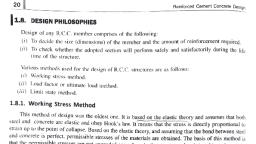
Reinforced cementoncrete Desiar, , Introductlon, 20, 1.8., , margins, , DESIGN PHILOSOPHIES, , Design of any, (i) To, , decide, , R.C.C., , member, , comprises, , (dimensions), , the size, , the adopted, , of the, , of the, , the, member and, , amount, , safely, section will perform, , of R.C.C., used for the design, , structures a r e, , and, , of reinforcement, , quired,, , reaiui, , satistactorily during, , Load factor, , (iii) Limit, 1.8.1., , or, , ultimate, , as follows:, , Working load, , (), , The method is more realistic as compared to working stress method because ultimate load, method takes into account the non-linear behaviour of the, , (ii), , This method gives exact margin of safety in terms of load unlike, is based on the permissible stresses which do not give any idea about the failure/collapse load., , (it), , Working Stress Method, , and assumes that both, oldest one. It is based on the elastic theory, This method of design was the, is, stress, the, directly proportional to, Hook's law. It means that, steel and concrete are elastic and obey, the bond between steel, that, and, assuming, the elastic theory,, strain up to the point of collapse. Based on, The, basis, of this method is, obtained., are, materials, the, of, and concrete is periect. permissible stresses, where in the structure when it is subjected to worst, are not exceeded, , any, , combination of working loads., , In this method, the ultimate strength of concrete and yield strength or 0.2% proof stress of steel are, divided by factors of safety to obtain pemissible stresses. These factors of safety take into account, the uncertainties in manufacturing of these materials. As per IS456, a factor of safety of 3 is to be, Used for bending compressive, in concrete and 1.78 for yield/proof strength of steel., , stresses, , The main drawbacks of the, , working, , stress method of, , design, , are as, , follows:, , i) It assumes that concrete is elastic which is not true as the concrete behaves inelastically even on, low level of stresses., , (i) It, , factors of safety for stresses, only and not for loads. Hence, this method does not give, of safety with respect to loads, because we do not know the failure load., (iii) It does not use any factor of safety with, respect to loads. It means, there is no, for tne, uncertainties associated with the estimation of, loads., (iv) It does not account for, shrinkage and, uses, , true, , margin, , provision, , concrete, working stress method which, , following, , The main limitations of the ultimate load method are, )This method gives very thin sections which leads to excessive deformations and cracking, thus, making the structure unserviceable., , (i), , No factors of safety, , are, , used for material stresses., , in, , 1.8.3. Limit State Method, This is the most rational method which takes into account the ultimate strength of the structure and, also the serviceability requirements. It is a judicious combination of working stress and ultimate load, , methods of design. 7he acceptable limits ofsafery and serviceability requirements before failure occus, load, a limit state. This method is based on the concept of safety at ultimate loads (ultimate, rwo important limit states to, The, stress, method)., and, Joads, (working, at, working, method), serviceability, is called, , be considered in design are:, , () Limit state of collapse., , (i) Limit state of serviceability., , 1.8.2. Load Factor Method, , (2) Limit State of Serviceability, , Ultimate Load Method, In this method,, ultimate collapse load is, used as, increasing the working/service loads, design load. The ultimate, the, suitably by, , o, , or, , ulumate loads, , loads are obla, factors., called as load These factors which are, mulup, factors. These load, factors give un, some, , are, , This limit state corresponds to the strength of the structure and categorized into following types:, Limit state of collapse: Flexure., state of collapse: Shear and bond., Limit, (b), Limit, state of coBlapse: Torsion., (c), , (a), , (d) Limit state of collapse: Compression., , This limit state corresponds to the, categorized into following types:, , or, , ed y, , hy, , exact, , method, the code replaced this, , this, As the serviceability requirements are not satisficd at all, as well as serviceability requirements., the, account, takes, into, which, method, state, limit, strength, method by, , (1) Limit State of Collapse, , understanding concepts design., , thinner and require less reinforcement., , method, , The sections designed by ultimate load, are, Hence the method is economical as compared to WSM., , creep which are time, dependent and plastic in nature, (v) This method gives uneconomical, sections., (vi) It pays no attention to the, conditions that arise at the, time of collapse., The working stress method is, method is to be used only if it is notvery simple and relíable but as per IS 456: 2000, the working su, possible to use limit state method of, is the basic method and its, design. Working stress, knowledge is essential for, is given in detail in, the, Chapter 2., thod, This, of, , working loads to obtain, , Collapseload, , clear margin of safety and one can easily tell the, load at which the structure fails, which is not clear from the working stress concept of permissible, stresses. This method was given in detail in IS 456-1964, the advantages of this method are listed below:, , load method., , stresses, , of concrete and steel, , Many designers feel that the load factor provides a, , state method., , that the pemissible, , =, , thelife, , stress method., , (i) Working, (ii) Load factor, , curve, , following:, , whether, (i') To check, structure., time of the, Various methods, , 21, , of safety in terms of load. This method uses the real stress-strain, and takes into account the plastic behaviour of these materials., , (a) Limit state of deflection., (b) Limit state of cracking, (c) Limit state of vibration., , serviceability requirements i.e., deformation, cracking etc., , It is
Page 11 :
Reinforced Cement Concrete, 22, , in, , varnalion, , This, , method, , is, , based upon, account, , the probabilistic, , associated, , the 10ads, with, , uncertainties, , the, , and, , loads, , material, , and material, , thus, , stresses., , loads and, , design, , takes into, which is d e t e r ., design, state method, s t r e s s method, to obtain, unlike working, factors of safety, accuratal, known, Uses partial, predictions, s t r e s s e s are, based on, material, method is, and, and are, statistics, safety, of, The limit state, and, factors, probability, the loads,, a s s u m e s that, derived using, procedtir, in nature,, factors are, scientific, rational and, the partial safety, a more, limit state method,, hence giving, combinations., load, for different, , c, , design, , method, , Deslgn, , oronerties., Limit, pror, , pronerti., , 3., detail in Chapter, is explained in, , tic, , the, nt, , This, , 3. The minimum compressive strength of 43 grade OPC cementis, (b) 43 N/mm, (a) 43 N/m, (d) 43 kg/mm*, (c) 43 kg/m, 4. IS 456:2000 recommends, (d) None of the above, (c) Limit state method of design, 5. The yield stress divided by the factor of safety is called as, , 1., , Concrete is, Concrete, , in, , is graded, , on, , the basis of, , prefered, , stresses., 8., , strain for concrete, , steel., , 8. HYSD bars are also known as, , 9., , theory., , 9. Working stress method is based upon, , 10. The modulus of elasticity of steel is taken as, , . N/mm., , 11. Concrete exposed to sulphate attack should be made from, , 12. Shrinkage of concrete is caused due to, , cement., , M10, , (b) M15, (d) M25, , The IS code for "mix design" of concrete is, (a), , IS 456:2000, , (b) IS 800:2007, , (), , IS 875:1987, , ( ) IS, , are, , 5. R.C.C. sections are, thicker as compared to, 6. TMT bars have, ex.cellent ductility., 7. Dead loads are, temporary loads., 8. Tensile, strength of concrete is equal to, 9. Working stress, method gives, collapse load., 10. Creep is a time, dependent, , plain, , () All of the above., , LANSWERS, (A) Fill in the Blanks:, , concrete sections., , 0.7 S, , (C) Multiple Choice Questions:, 1. The, reinforcement in R.C.C., (a) Tensile stresses, , phenomenon., , expansion, , 1. Tension, , 2. 25000 N/m, , 3. Compressive strength, , 4., , 5. Tensile, , 6. M20, , 7., , 50, , 9., , Elastic, , High yield strength deformed (HYSD), , 8. Tor, 10. 2 x 10, 12. Loss, , 11. Sulphate resisting, (B) State True/False:, , takes, , (c) Shear stresses, of thermal, , 10262:2009, , (b) Age at loading, , Stress level, , compression., compressive strength., , ductile than mild steel., heavier than steel, structures., more, , as, , (b) 350 kg/m, (d) 280 kg/m*, , (c) Duration of loading, , 3. High strength steel is, , be taken, , Minimum cement content for M20 mix in RCC is, , (a), , 4. R.C.C. structures, , can, , (b) 0.003 mm/m, , 10. Creep strain depends upon, , of moisture., , (B) State True/False:, 1. Concrete is strong in tension and, 2. Cement is, graded on the basis of, , per IS 456, , as, , (a) 300 kg/m, (c) 375 kg/m', , kg, , 7. One bag of cement in India weighs, , (c) Steel, , shrinkage, , (c) M20, , (a), , should not be used for R.C.C. work., , 6. Concrete grades lower than, , coefficient, , (d) Permissible stress, , ., , over mild steel bars., , 5. In R.C.C.. steel reinforcement takes up, , 2. The, (a) Wood, , c) Elastic stress, , (d) 0.002 mm/m, (c) 0.004 mm/m, 7. Nominal mix is not used for grades higher than, , of R.C.C. is, , bars are, , 4., , (b) Limit stress, , (a) 0.005 mm/m, weak, , very, , 2. The unit weight, 3., , (a) Ultimate stress, 6. The ultimate, , Fill in the Blanks:, , (b) Ultimate load method of design, , (a) Working stress method of design, , OBJECTIVE TYPE QUESTIONS, , (A), , 23, , Introduction, , (b) Compressive stresses, (d) Torsional stresses, of, , concrete, , is, , nearly equal, , (b) Aluminium, d) Copper, , to, , 1. False, 6., , True, , 5. False, , 2. True, , 3. False, , . True, , 7. False, , 8. True, , 9. False, , 10. True, , 3. 6), (a), , 4. (c), , 5. (), 10. (, , (C) Multiple Choice Questions:, , (a), 6. (b), , 2. 6, 7. (c), , 9. (d)
 Learn better on this topic