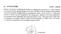
Page 1 :
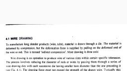
3.1. INTRODUCTION, , ect ving, Forging can be defined as a method of shaping heated metal by compression. a ek, goes back to 8000 B.C. and evolved trom the manual art of simple blacksmithing. Ne Spe oe, that a blacksmith use, are various kinds of dies. swages and fullers. Modern forging —, driven impact hammers or presses which deform the workpiece by controlled pressure. rging, , process ~ . . ae jy defined, Process is superior to casting in that the parts formed have dense microstructy es, more de, gram patterns, i rts st v casting., , n pa ns. and less porosity, making such parts much stronger than a casting., , , , , , Forgings usually have great strength. as compared with other methods of producing products., Vhe process of kneading the metal produces a very beneficial grain flow. When a part is machined,, the grains are cut. resulting in short. broken grain lines. However. in forging the grains remain unbroken, and w it assume the contour of the part (see Fig. 3.1). Here, it is easy to see that the grains. not only, remain unbroken. but have formed a tough. fibrous structure conforming to the outline of the part., , , , , , , , , , , , Fig. 3.1. Grain flow., , Forging involves, basically. three different operations. The first is drawing. This is increasing the, Jength of the metal while decreasing the cross-sectional area. The second o, involves reducir, , , , peration is upsetting. This, al area. The third operation, , metal. but will not increase the cross-sectional area. In fact, the, , cross sectional area ts usually decreased as the metal changes shapes. These three c:, when the flow stress is reached., , he length of the metal while increasing the cross-section:, S squeezing. This will lengthen the, , ‘an only be achieved, As seen in stress-strain diagrams. the viel, , y. Durin, , , , d point is the point where the material changes from, stress builds up when the hot m, , etal is squeezed between dies, etormation. When the yield Point is reached, plastic deformation, less of the strain., , , , c, occurs under the same stress regard
Page 2 :
Forging 21, , dra i ’ : . : : : s ‘ ig |, I ft sg and squeezing are not major considerations in forging, however, upsetting is. This is, because the metal is being forced back on itself and the metal really doesn’t want to do this. There, , are several guidelines that have to be considered when upsetting metal. The method being used-hand, forging. drop forging, ete. does not effect the upsetting., , 3.2 TYPES OF FORGING PROCESSES, , Forging is classified into three categories :, Open-die,, Impression-die and, Closed-die forging., , 3.2.1 Open Die Forging [UPTU: 2006-07], , Open-die forging is a hot forging process is which metal is shaped by hammering or pressing between, “at or simple contoured dies (see Fig. 3.2). In open die forging, the dies do not completely cover the, svorkpiece. Tistead, there are open spaces thatattow various aspects of the workpiece to move from, direct hot die contact, and to cooler open areas. In this type of forging, metals are worked above, their recrystallization temperatures. Because the process requires repeated changes in workpiece, positioning. the workpiece cools during open die forging below its hot-working or recrystaliization, , temperature. It must be reheated before forging can continue., , Die |, Friction, forces, Workpiece, Barreling, , Fig. 3.2. Open die forging., , , , , , , , , , , , Operations performed on open die presses include :, , 1. Drawing out or reducing the cross-section of an ingot or billet to lengthen it., , 2. Upsetting or reducing the length of an ingot or billet to a larger diameter., , 3. Upsetting. drawing out, and piercing-processes sometimes combined with forging over a mandrel, , for forging rough-contoured rings., , Advantages, Practically all forgeable ferrous and non-ferrous alloys can be open-die forged, including some exotic, materials like age-hardening superalloys and corrosion-resistant refractory alloys., , Applications, Open-die shape capability is indeed wide in latitude. In addition to round, square, rectangular, hexagonal, , bars and other basic shapes, open-die processes can produce :
Page 3 :
22 Manufacturing Science 1, , © Step shatts, satid shafts (spindles or rotors) whose diameter increases or decreases (steps down), SUMUTIpTe looations along the longitudinal axis, , * Hottow cevtindrical shapes, usually with length much greater than the diameter of the part, Length,, Wall thickness, internal and outer diameter can be varied as needed, , © Ring-like parts can resemble Washers or approach hollow cylinders in shape, depending on the, hemehuwall thickness ratio, , ., , ate ¢ r, Comourtormed metal shells like pressure vessels, which may incorporate extruded nozzles, and other design features, , Open die forging is further classified as hand forging and power forging., () Nand forging : Sometimes called smithy, or blacksmithing, hand forging is the simplest form, © fSeaiNE and it ty one of the methods by which metal was first worked, The metal to be forged is, heated to red heat in the tire of a forge, and then is beaten into shape on a metal anvil with, Sledges or hammers. The torge consists of an open hearth, made of some durable, refractory substance, firebrick, whieh is provided with a number of air openings, or tuyeres, through which air is, forced by a bellow or blower fan Charcoal, coke, and coal are used as fuels in the forge, , , , , , , , such as, , Hand Forging Tools and Equipment [UPTU; 2001-02, 2002-03], Besides a furnace hand forging needs anvil, swage block. blacksmith hammers. tongs. swages, fullers, and Matters for the various forging operations, These are discussed below., , 1. Anvil (see Fig, 3.3) : An anvil acts as a supporting device which is capable of withstanding, , heavy blows rendered to the job. It is made of cast steel, wrought iron or mild steel provided, with a hardened top. The horn or beak is used in bending the metal or forming curved shapes., , \tthe top of the anvil, is a square and a round hole. The square hole (also known as hardie hole), ts used for holding square shank. s, , , , haped tools like bottom fullers, swages etc. The round hole, is used for admitting the ends of the punches or drifts. This hole is also used for bending round, , bars of different curvatures. The anvil is supported either on an iron base or on a wooden block., , , , Hardie hole, , , , , Face, Cutting face, , Punching, - hole, , Body
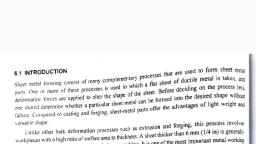
Page 4 :
Forging 23, , 2. Swage block (see Fig. 3.4) : It is generally made of cast iron and has round, square, rectangular, and half round grooves. These grooves are used either for holding bars while bending or providing, support in punching holes. The swage block is supported on a cast iron stand., , , , , , , , , , , , , , , , , , , , , , Fig. 3.4. Swage block., 3. Hammers (see Fig. 3.5) : These are basically of two types—, , (i) Hand hammer, and, , (ii) Sledge hammer., CROSS PEIN, , BALL PEIN STRAIGHT PEIN, , , , , , Fig. 3.5. Various types of hammers., , The hand hammers are generally ball peen hammers. These have a slightly convex striking face, , and generally weigh from | to 1.5 kg.
Page 5 :
2 A ee ee SP et, , Manufacturing Science,, , 24, , 1 than the hand hammers. These are useq, , The sledge hammers are usually 3 to 4 times heavie further classified as cross peen, straight, when heavy blows are needed in forging. Sledge hammers are Tu, peen and © fi ., t d double faced type. position during forging. Tongs are, , 4. Tongs (see Fig. 3.6) : These are used for holding the pete inner shape of the jaws., made of mild steel and are usually named according to the, , , , ee ee, SS, , Flat bit tongs, , , , Pick up tongs, Fig. 3.6. Various types of tongs., 5. Swages (see Fig. 3.7) : These are used in Pairs i.., top and bottom parts. Swages are used to, , reduce and finish the job to the exact size and shape. During swaging the workpiece is rotated, between swages. which is hammered to produce smooth round surface.