Page 1 :
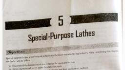
Considering the versatility, a large number of variants of lathes are used in manufacturing shops. The, ( 4, Centre Lathe, Objectives, Centre lathe is the most common and versatile machine found in practically all machine shops. After completing, the chapter, the reader will be able to, • Understand the importance of lathe and its many varieties, • Understand the basic structure of a centre lathe, • Choose various aids used to locate and support workpieces in a lathe, • Select the large variety of cutting tools used in a lathe, • Practice a variety of common operations performed in a lathe, • Understand the various methods used to carry out the taper-turning operations in a lathe, • Understand the requirements and the methods to be used to cut precision threads in a lathe, Estimate the machining time and power required for any given operation in a lathe, • Plan typical set-ups that can be done in a lathe, 4.1, INTRODUCTION, Lathe is the oldest machine tool invented, starting with the Egyptian tree-lathes. In the Egyptian tree-lathe,, one end of the rope wound round the workpiece is attached to a flexible branch of a tree while the other end, is pulled by the operator, thus giving rotary motion to the workpiece. This primitive device has evolved over, the last two centuries to be one of the most fundamental and versatile machine tool with large variants to be, used in practically all manufacturing shops., The principal form of surface produced in a lathe is the cylindrical surface. This is achieved by rotating, the workpiece while the single-point cutting tool removes the material by traversing in a direction parallel to, he aris of rotation as shown in Fig. 4.1, and it is termed hurning. The popularity of lathe is in view of the fact, that a large variety of surfaces could be produced., variations are, 1. Centre lathe, Bench lathe, 2. Tool-room lathe, 3. Special-purpose lathes, Copying lathe, Scanned with Camscanner
Page 2 :
Centre Lathe, 107, Dog plate, Dog, Rotation of the, workpiece, -Depth of cut, Dead centre, Feed, Live centre, Fig. 4.1 Cylindrical turning operation in a lathe, • Gap-bed lathe, • Hollow spindle lathes, 4. Capstan and turret lathes, 5. Automatic lathes, The centre lathe is the most common of the lathes, which derives its name from the way a workpiece is, clamped by centres in a lathe, though this is not the only way in which the job is mounted. This is sometimes, also called engine lathe in view of the fact that early lathes were driven by steam engines. This is generally, used for more general applications and thus the construction of the machine tool is more rigid. This is discussed, in greater detail in this chapter., The tool-room lathe is generally meant for applications of toolmaking, where the accuracy desired is much, higher than normally required for general production work. Also, the range of sizes and materials handled, would normally be large. Thus, the machine would have a higher range of speeds and feeds along with greater, rigidity. Also, the range of accessories and attachments would generally be larger., The special-purpose lathes are developed from the centre lathe to cater to special forms of application,, which cannot be handled by the conventional centre lathe., Capstan and turret lathes and automatic lathes are the form of lathes to cater for high-rate production and thus, would be used for very special applications. These have special features to help in improving the production, rate and also work unattended if necessary. These are discussed in the next chapter., 4.2, CONSTRUCTIONAL FEATURES OF A CENTRE LATHE, The typical centre lathe is shown in Fig. 4.2. The major elements present in the lathe are explained below., The headstock houses the power source, all the power transmission, gear box and the spindle. The headstock, is fixed at the leftmost end on the bed. The spindle is hollow, should be sufficiently rigid to provide accurate, rotary motion and maintains perfect alignment with the lathe axis. A live centre fits into the Morse taper in, the spindle hole for the purpose of locating the workpiece axis., Scanned with Camscanner
Page 3 :
The third major element in the lathe mechanism is the carriage, which provides the necessary longitudinal, The motion from the spindle motor is communicated to the carriage through a lead screw. Engagement of the, on the bed to accommodate the different lengths of workpieces. It also serves the purpose of holding tools such, locating the long components by the use of centres. The tailstock is movable on the inner guideways provided, as centre drill, twist drill, reamer, etc., for making and finishing holes in the components, which are located, motion to the cutting tool, to generate the necessary surfaces. This also houses the cross-slide for giving, motion (cross-feed) to the cutting tool in a direction perpendicular to the axis of rotation; the compound slide, which provides an auxiliary slide to get the necessary special motion for specific surface generations; and the, lead screw with the carriage is through the use of a half nut. Though the lead screw could be used for feeding, 108, Manufacturing TechnalagY, Headstock, Adjustment, Feed, Spindle, revolves, Spindle speed, Toolpost, Carriage (saddle), Cross-slide, Spindle does, not revolve, Tailstock, Feed change, gear box, Compound, rest and, slide (swivels), Feed rod, Bed, Lead screw, Fig. 4.2 General view of a centre lathe showing various mechanisms and features, The main gear box provides the necessary spindle speeds considering the range of materials to be turned, in the lathe, The headstock also houses the feed gear box to provide the various feed rates and thread-cutting, ranges., The tailstock is towards the rightmost end on the bed, and houses the tailstock spindle for the, purpose, of, in-line with the axis of rotation., toolpost which allows for the mounting of the cutting tool., Scanned with CamScanner
Page 4 :
Centre Lathe, 109, the cutting tool in a direction parallel to the axis of rotation, many a times a separate feed rod is provided for, this function. The main reason is that the lead screw would be more accurate and would be sparingly used, only for thread cutting, such that it would maintain its accuracy. For routine feeding, the feed rod is used., Lathe Specifications, In order to specify a lathe, a number of parameters, could be used based on the specific application., However, the major elements used for specification, should invariably be based on the components, that would be manufactured in the lathe. Thus, the, following are the basic elements generally specified, for the capability of the lathe machine (Fig. 4.3)., • Distance between centres-This would be, specifying the maximum length of the job that, can be turned in the lathe., Fig. 4.3 Capacity specifications for a lathe, • Swing over the bed-This specifies the maximum diameter of the job that can be turned in the lathe, machine, generally restricted to small-length jobs., • Swing over the cross slide-This specifies the maximum diameter of the job that can be turned in the, lathe machine with the job across the cross slide, which is often the more general case., Though the above gives the basic capacity of the machine as shown in Fig. 4.3, there are a number of other, factors that should also be specified to fully describe the lathe machine. They are, • Horsepower of the motor, • Cutting-speed range, • Feed range, • Screw cutting capacity, Accuracy achievable, • Spindle nose diameter, • Hole size, Typical specifications of some centre lathes are given in Table 4.1., Table 4.1 Specifications of centre lathes, Centre height, mm, 250,300, 375,450, 525,600, 750,900, Bed width, mm, 325,375, 450,550, 650,750, 900,1050, Sizes available, mm, 1650 to 4200, 2400 to 9600, 2400 to 9600, 2400 to 9600, Distance between centres (mm), 500 to 3100, 1000 to 8200, 800 to 8000, 3, 7.5/10, 10/15, Power capacity, HP, Spindle-speed range, 30 to 550, 30 to 350, 15 to 200, 15 to 200, Further specifications would be based on the accessories used with the machine tool and their respective, capabilities., Scanned with Camscanner
Page 5 :
110, Manufacturing Terhnolagy, 4.3, AIDS FOR SUPPORT AND LOCATION, The work-holding devices normally used should have the following provisions:, itable location,, offective clamping, and, upport when required., The most common form of a work-holding device used in a lathe is the chuck. Chucks come in various, forms with varying number of jaws. Of these, the three-jaw chuck or the self-centering chuck, as shown in, Fig. 4.4, is the most common one. The main advantage of this chuck is the quick way in which the typical, round job is centred. All the three jaws would be meshing with the flat scroll plate. Rotating the scroll plate, through a bevel pinion would move all the three jaws radially inward or outward by the same amount. Thus,, the jaws would be able to centre any job whose external locating surface is cylindrical or symmetrical like, hexagonal. Though it is good for quick centering, it has limitations in terms of the gripping force and also the, accuracy is gradually lost due to wear of the mating parts., Bevel teeth, on scroll plate, Jaw, Scroll, plate, Bevel, pinion, Fig. 4.4, Three-jaw chuck and principle of operation, The independent jaw chuck has four jaws, which can be moved in their slots independent of each other, (Fig. 4.5), thus clamping any type-of configuration. Since each of these jaws could move independently, any, irregular surface could be effectively centred. Better accuracy-in location could be maintained because of the, independent movement. However, more time is spent in fixturing a component in a 4-jaw chuck compared to, the 3-jaw chuck. This is generally used for heavy workpieces and for any configuration., The jaws in a 4-jaw chuck could be reversed for clamping large-diameter workpieces as shown in Fig. 4.6., The soft jaws are sometimes used in these chucks for clamping surfaces of a component, whose surface is, already finished and which is likely to be disfigured by the hard surface of the normal jaws used in them., The 3-jaw and 4-jaw chucks would normally be suitable for short components. However, in the case of, long components, supporting at only one end, as is done in the case of chucks, would make it deflect under, the influence of the cutting force. In such cases, the long workpieces are held between centres. The workpiece, ends are provided with a centre hole as shown in Fig. 4.7. Through these centre holes, the centres mounted in, the spindle and the tailstock would rigidly locate the axis of the workpiece., Scanned with Camscanner