Page 1 :
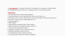
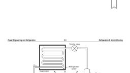
Ideal vapour refrigeration cycle:, A schematic of an ideal vapour compression refrigeration cycle and its T–s diagram are shown in Fig., , The vapour compression refrigeration cycle consists of four processes discussed below:, Process 1–2 isentropic compression of saturated vapour in the compressor,, Process 2–3 Constant pressure heat rejection in the condenser,, Process 3–4 Throttling of refrigerant in an expansion device, and, Process 4–1 Constant pressure heat absorption in evaporator.
Page 2 :
Working:, In an ideal vapour compression cycle, the refrigerant enters the compressor at the state 1, as dry and, saturated vapour, where it is compressed to a relatively high pressure and temperature, the state 2. The, refrigerant in the superheated state 2, enters the condenser and leaves as saturated liquid at the state 3,, as a result of heat rejection to the surroundings. The saturate liquid refrigerant at the state 3 is throttled to, the evaporator pressure by passing through an expansion valve or a capillary tube. The temperature of, refrigerant at the state 4 drops below the temperature of the refrigerated space. At the state 4, the, refrigerant as wet mixture passes through an evaporator at constant pressure. The refrigerant is now, completely evaporated by absorbing its latent heat from cold temperature (refrigerated) space. The heat, absorbed during evaporation of refrigerant is the latent heat and its magnitude is higher at low pressures., The only throttling process 3– 4 is an irreversible process and hence it is shown by dotted lines. The, remaining three processes are considered reversible. Therefore, the vapour compression cycle is not a, reversible cycle., , Analysis of Vapour Compression Cycle:, All four components in a vapour compression cycle are steady flow devices., 1., 2., 3., 4., , Evaporator (w = 0) ,qL = h1 – h4, Compressor (q = 0) win = h2 – h1, Condenser (w = 0) qH = h2 – h3, Expansion valve (q = 0, w = 0) h4 = h3, , The coefficient of performance of refrigerator and heat pump can be expressed as
Page 3 :
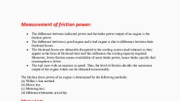
Effect of operating conditions on the performance of the vapour compression cycle:, 1. Effect of Evaporator pressure:, , , , , , , , , Refrigeration effect= (h1’ – h4’), decreases., Compressor Work= (h2’– h1’), increases., COP decreases., The specific volume of vapour at low, pressure is large, thus the volumetric, efficiency will also decrease., Therefore, it is not desirable to, decrease the evaporator pressure., , 2. Effect of Condensor pressure:, , , , , , , , The work input to the compressor, increases from 1–2 to 1–2’, Refrigerant effect decreases from 4–, 1 to 4’–1., The condenser temperature, increases, thereby increasing heat, rejection., The COP of the system decreases.
Page 4 :
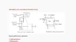
3. Effect of superheating at Suction Side, , 4. Effect of Liquid Sub cooling(or Under cooling):, , Refrigeration effect increases., Compression work is constant., COP increases.
Page 5 :
ICE PLANT:, , The main cycle used for this plant is Vapour Compression Cycle with Ammonia as a primary refrigerant, circuit and Brine as a secondary refrigerant circuit. The function of an ice plant or ice factory is to make or, form ice in large quantity and in large size. The ice making process is quite similar to the one we observe, in a domestic refrigerator. The only difference lies in the ice making the stage. In the freezer, compartment, the tray with water when it comes in contact with very low-temperature environment,, becomes ice but in an ice plant which is a huge commercial factory, it uses separate ice making or ice, freezing circuit. The cold is produced in one circuit and it is transferred to the water cans by another, circuit., , , , Ammonia: It is the primary refrigerant which takes heat from brine. This ammonia changes phase, while moving in the circuit, Brine: It is the secondary refrigerant which takes heat from the water and produces ice., , Construction, , , Compressor: Its function is to increase the temperature and pressure of Ammonia vapor coming, out from evaporator.
Page 6 :
, , , , , , Condenser: It liquefies the high-pressure and high-temperature Ammonia to high-pressure and, high-temperature Ammonia. Here chilled water comes in contact with the high-pressure and hightemperature ammonia and provides the temperature for condensation. The heated water is, pumped and again taken to circuit after it has been cooled at natural cooling tower, Receiver: It is used to collect the liquid Ammonia from the condenser., Throttle Valve: It expands Ammonia coming out from receiver to low pressure., Evaporator: It vaporize the liquid Ammonia from throttle valve by extracting heat from 'brine' and, hence brine gets cooled and this brine solution is recirculated to water tank containing 'ice cans, filled with water' to absorb the heat of water to freeze it and make ice., , Working, , , Low pressure and low-temperature Ammonia coming out from the throttle valve is vaporized by, taking the latent heat from the brine. Hence brine gets cooled which is circulated in the brine, circuit to freeze the water and forming an ice from water., , , , , This cooled brine further absorbs the heat from water and converts water to ice., Vaporized Ammonia is compressed to high pressure and temperature and passes from, condenser., In condenser Ammonia is condensed by water circulated in cooling water circuit having a natural, cooling tower. The condenser condenses the Ammonia by water coming from natural cooling, tower., , , , Cold Storage Plant:, , Cold storage basically works on the 'vapour compression refrigeration cycle' to produce cooling., , Construction of cold storage plant, , , Compressor:, Compressor is the heart of the cold storage plant and only power-consuming device. It raises the, temperature and pressure of refrigerant ( Ammonia) vapour coming out from an evaporator.
Page 7 :
, , Condenser:, It is a heat exchanger device which exchanges the heat from vapour refrigerant and water being, circulated. The condenser is not powered consuming device. It condenses the high-pressure and, high-temperature refrigerant to the high-pressure and high-temperature liquid., , , , Receiver:, It receives the high-pressure liquid condensate from the condenser and collects it., , , , Expansion Valve:, It reduces the pressure and temperature of refrigerant from receiver pressure and temperature to, evaporator pressure and temperature. The throttling process makes pressure and temperature, reduction., , , , Evaporator:, The heat exchanger where actual cooling takes place. It evaporates (vaporize) the low-pressure,, low-temperature liquid refrigerant (with a low boiling point) by taking/utilizing heat from, atmosphere/storage compartment to be cooled, thus heat content of fruits or vegetable decrease, and it cool due to this cyclic process (Chilled air is produced due to convection current), , , , Blowers: It circulates chilled air in the refrigerated space to cool the fruits and vegetables by, convection process., , Working of cold storage plant, , , , , , , , The compressor compresses vaporized refrigerant (Ammonia) to high pressure and high, temperature to raise the boiling point of refrigerant., The condenser then liquefies the vaporized refrigerant to high-pressure and high-temperature, state. Thus, heat rejection takes place., The condensate from the condenser is collected in a reservoir and allows passing through an, expansion valve where its pressure and temperature decrease from an earlier state., The the low-pressure liquid refrigerant then allows passing through refrigerated space whereby, the heat of hot air of refrigerated space starts evaporating the liquid refrigerant hence, heat in the, atmosphere decrease and cooling is produced., Blowers circulate the chilled air to stored fruits and vegetables.