Page 2 :
Experiment No. - 01, TITLE – TO FIND UNKNOWN ANGLE OF COMPONENT USING SINE BAR AND SLIP GAUGES., INTRODUCTION- A sine bar is used in conjunction with slip gauge blocks for precise angular, measurement. A sine bar is used either to measure an angle very accurately or face locate any, work to a given angle. Sine bars are made from a high chromium corrosion resistant steel, and, is hardened, precision ground, and stabilized., , APPARATUS – The experiments requires following equipments, 1. sine bar , height gauge, 2. surface plate , set of standard slip gauges , dial indcator, 3. component whose angle is to be measured, , DIAGRAM –, , PRINCIPLES, , , , , , , The application of trigonometry applies to sine bar usage., A surface plate, sine bar, and slip gauges are used for the precise formation of an angle., It is possible to set up any angle ϴ by using the standard length of side AB, and calculating, the height of side BC using BC = AB * sin(ϴ)., The angle ϴ is given by ϴ = asin(BC/AB)., Figure 1 shows a typical sine bar set up on a surface plate with slip gauge blocks of the, required height BC to form a desired angle ϴ
Page 3 :
PROCEDURE, 1. To set an angle on any sine bar, you must first determine the center distance of the sine bar, (C), the angle you wish to set (A) and whether the angle is in degrees-minutes-seconds or, decimal degrees., 2. Next, enter that information in the appropriate input areas below. Use a decimal point for the, separator, whether the angle is in degrees-minutes-seconds or decimal degrees., 3. Hit the ‘Calculate’ button and then assemble a stack of gauge blocks (G) to equal the size that, is returned. The units of the stack will match the units of the center distance (i.e., If you enter, the center distance as 5 for a 5 inch sine plate, the gage block stack will also be in inches.)., 4. Place these slip gauges blocks under the gauge block roll of the sine device and the desired, angle is set., 5. Tighten the locking mechanism on those devices that have one and you’re ready to go.
Page 4 :
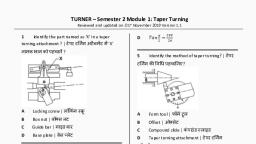
6. Study the bevel protractor and identify its main parts., 7. Introduce the adjustable blade in the slot of body and clamp it with the help of knob In the, convenient position., 8. Place the working edge of the stock on one surface of the job and rotate the turret holding the blade, so that the working edge of the blade coincides with another surface of the job. Fix the turret and read, the angle. And now measure the angles of the sample pieces with the bevel protractor and record the, reading., , SINE BAR SET-UP CALCULATION, To calculate the gauge block’s height needed to set-up a sine bar to a specific angle all you have, to do is take the SIN of the angle and multiply it by the sine bar length. The length of the sine, bar is the distance between the centers of the sine bar gauge pins., , OBSERVATION:, 1. Length of sine bar=L=200 mm, 2. size , h=68.6, 3. specimen angle with vernier bevel protractor=68.6 4. centre distance=200 mm, 5. ø=sin-1(h/L)= 20.097, 6. angle of specimen=20.1, 7. least count of dial indicator=0.001 mm, , SINE BAR USAGE, To measure a known angle or locate any work to a given angle:, 1. Always use a perfectly flat and clean surface plate., 2. Place one roller on the surface plate and the other roller on the slip gauge block stack of, height H., 3. Let the sine bar be set to an angle ϴ., 4. Then sin(ϴ) = H/L, where L is the distance between the center., 5. Thus knowing ϴ, H can be found and any work can be set out at this angle as the top face of, the sine bar is inclined at angle ϴ to the surface plate.
Page 5 :
6. For better result both rollers must placed on slip gauge block of height H1 and H2, respectively. See above figure,, CONCLUSION: Hence we have studied various angle measuring instruments, , Experiment No. – 02, TITLE: Measurement of gear tooth thickness by gear tooth Vernier Calliper/Constant Chord/Spam, micrometer., , APPARATUS: Gear tooth vernier caliper, vernier caliper 12’’ 300 mm, bench vice., THEORY: Brief description of different characteristics of measuring of tooth thickness by gear truth, vernier is given. It consists of a horizontal and a vertical vernier scale. It is based on the principle of, vernier scale. The thickness of a tooth at pitch line and the addendum is measured by an independent, tongue each of which is adjusted independently by adjusting the slide screws on graduated beams., , TERMINOLOGY OF GEAR TOOTH, , GEAR TOOTH, , VERNIER CALIPER
Page 6 :
(i) Pitch circle diameter (PCD) : It is the diameter of a circle which by pure rolling action would produce, the same motion on the toothed gear wheel. It is equal to D = (T X OD)/(T+2)OD = outside diameter T =, number of teeth, (ii) MODULE: It is defined as the length of the pitch circle diameter per truth. Module m=D/T and is, expressed ih mm, (iii) CIRCULAR PITCH (CP) : It is the arc distance measured around the pitch circle from the flank of one, truth to a similar flank in the next 1.00th CP==ΠD/T=Πm., (iv) ADDENDUM: This is the radial distance from the pitch circle to the tip of the truth. It is equal to one, module., (v)Clearance: This is the radial distance from the tip of a tooth to the bottom of the mating tooth space, when the teeth are symmetrically engaged. Its standard value is 0.157m or 0.25m., (vi) DEDENDUM: This is the radial distance from the pitch circle to the bottom of tooth space.Dedendum, = Addendum +Clearance = m +0.157m =1 .157m.=1.25m (metric gearing system), (vii) TOOTH THICKNESS: This is the arc distance measured along the pitch from the intercepts with one, flank to the intercepts with the other flank of the same tooth., , VERNIER TOOTH CALIPER GEAR TOOTH DETAILS PROCEDURE:, For finding PCD, module, addendum, dedendum and clearance:, 1. First find the blank diameter, OD by a vernier caliper and also count the number of teeth T of the spur, gear., 2. Next calculate pitch circle diameter D=(TxOD)/(T+2), 3. Find addendum, clearance, pitch, module and dedendum as per the formulae given in the theory., FOR CHORDAL TOOTH THICKNESS (using gear tooth calliper):, 1. Set the chordal depth (addendum) on the vertical slide of the gear tooth vernier and then insert the, jaws of the instrument on the tooth to be measured., 2. Adjust the horizontal vernier slide by the fine adjusting screw so that the jaws just touch the tooth., 3. Read the horizontal vernier slide and note the reading. It gives the chordal thickness of tooth., 4. Repeat the observations for the different teeth., 5. Compare the values of different characteristics with the standard value and set the percentage error., , OBSERVATION:, 1. Least count of caliper= 0.02mm, 2. Number of teeth= 40, TABLE FOR SETTING GEAR TOOTH CALLIPER FOR SPUR GEAR
Page 7 :
CALCULATIONS:, 1. Pitch circle diameter, D=(TxOD)/(T+2)=, 2. module, m=D/T mm=, 3. Addendum=m=, 4. Dedendum=m+0.157m=, , CONCLUSION: Hence we have various gear parameters of gear using vernier gear caliper., , Experiment No. – 03, TITLE: Study of circularity/ Roundedness using mechanical comparator., APPARATUS:, Mechanical comparator-with Dial indicator and Work piece-Any 10 jobs of size within the range of, comparator and master jobs., , THEORY: The comparator is a device which takes a dimension of standard job as reference dimension,, and gives a reading to a pointer on a scale, the variation In such dimension of the job to be compared., upper end of the vertical beam, an adjusting screw is provided for final zero setting of the scale. A new, patented feature is shown at K. This js a magnetic counter balance which serves to neutralism the, positive 'rate' of spring reaching on the measuring tip. In this way a constant pressure over the whole, scale range is achieved. The instrument is available with vertical capacities of 6’, 12', and 24,' and, magnification of 500, 1000, 500, 3000 and 5000. The scales are graduated both in English and Metric, systems. The least count is of order of 10R Inch. A work table on the base of this comparator stand is, used to keep the job on. Special attachments are used for typical jobs like screw thread, effective/outside diameter. Dial indicator type of mechanical comparator consists of a sensitive dial, indicator mounted on a horizontal arm on a stand. The arm is capable of coarse and fine adjustment, movements in the vertical direction for initial setting of the Instrument. The base is heavy so that
Page 8 :
stability and rigidity of the instrument is ensured. Different attachments are available depending upon, the type or job., , PROCEDURE:, (i) Clean the comparator with a flannel cloth or chastise leather., (ii) Wipe the standard job clean of dust etc., (iii) After lifting anvil by pressing the trigger, mount the standard jobs/slip gauges on the work table., (iv) Adjust the screw at the top of vertical beam to zero pointer reading., (v) Replace the standard job with sample job and record the reading on scale., (vi) Repeat the comparisons for -eat of sample jobs. Classify the jobs into acceptable/not acceptable, and give code number for selective assembly., , OBSERVATION TABLE:, ROUNDNESS, , CONCLUSION:, , Hence we have measured the roundness using the mechanical comparator., , Experiment No. – 04, , TITLE: Determination of Linear\Angular dimensions of a part using Precision\non-precision measuring, instruments.
Page 9 :
APPARATUS, , : Steel Rule, Vernier Caliper, Vernier Height Gauge, Micrometer, Digital Vernier, , Caliper, Digital Micrometer., , THEORY:, STEEL RULE: It is also known as scale. It is the line measuring device. It is the simplest and common, measuring instrument used for inspection. It works on the basic measuring technique of company on, unknown length to the one previously calibrated. It consists of a strip of hundred steel having line, graduation etched engraved on internal of fraction of standard unit of length, depending upon the internal, at which graduations are made. The scale can be manufactured in different sizes and styles. It may be 150, mm, 300 mm, 600 mm or 1000 mm long., , VERNIER CALLIPER: The principle of vernier is that when two scales or divisions slightly different, in size are used, the difference between them can be utilized to enhance the accuracy of measurement., The Vernier Calliper essentially consists of two steel rules and these can slide along each other. The, details are shown in fig. below, 1. Outside jaws: used to measure external diameter or width of an object, 2. Inside jaws: used to measure internal diameter of an object, 3. Depth probe: used to measure depths of an object or a hole, 4. Main scale: gives measurements of up to one decimal place (in cm)., 5. Main scale: gives measurements in fraction(in inch), 6. Vernier gives measurements up to two decimal places(in cm), 7. Vernier gives measurements in fraction(in inch), Least count, Least count = value of 1msd/total no. Of vsd, 1 msd = 0.1mm, total no. Vsd = 5 therefore LC = 0.02mm t, Suppose 50 vernier scale I division coincide with 49 divisions on main scale, and 1 msd=1 mm.Then 1, VSD = 49/50 of MSD = 49/50MM.and LC = 1-49/50= 0.02 mm.Alternatively, it is just as easy to read the, 13 on the main scale and 42 on the hundredths scale. The correct measurement being 13.42mm., 1 cm = 10mm, , VERNIER HEIGHT GUAGE: This is also a sort of a vernier caliper equipped with a special base back, and other attachments which make the instrument suitable for height measurement. Along with the sliding, jaw assembly arrangement is provided to carry a removable clamp. The upper and the lower surface of the
Page 10 :
measuring jaw are parallel to the base so that it can be used for measurement over or under the surface., The vernier height guage is merely used to scribe lines of certain distance above surface. However, dial, indicator can be attached in the clamp and many useful measurements can be exactly made as it exactly, gives the indication when dial tip just touches the surfaces. For all these measurements, use of surface, plates as datum surface is very essential., , MICROMETER: The micrometer essentially consists of U shaped frame. The component to be, measured is held between fixed anvil and movable spindle. The spindle can be moved with the help of, thimble. There are two scales on micrometer, a main scale and a circular scale. The barrel is graduated in, unit of 0.5 mm whereas thimble has got 50 divisions around its periphery. One revo-lution of thimble, moves 0.5 mm which is the lead of the screw and also the pitch. 2.5 mm+ (46*0.01) = 2.96 mm, DIGITAL MICROMETER:, 1) It is used where high accuracy is required., 2) It is based on electronic technology., 3) It can be zeroed at any position, which greatly speeds the process of inspection., , V BLOCK: The Vee-block is essentially tool steel blocks that are very precisely 100mm square., Standard Veeblocks come as 45 degree block, i.e. the vee-sides slope 45 degree from horizontal or, vertical, the included angle of the vee being of course, 90 degrees. But blocks with different angles and, shapes are also available. For special purpose such as checking triangle effects or for taps and other, threefluted tools, 60 degree Vee-blocks are also available. The included angle of the vee then is 120, degrees. The major purpose of the Vee-blocks is to hold cylindrical pieces, or move to the point, to, establish precisely the centre line or axis of a cylindrical piece. In using a vee-block, it is very essential, that the cylindrical piece should rest on firmly on the sides of the vee and not on the edges of the vee. H &, G Magnetic V Block, All sides are hardened and ground,Used for grinding, light Milling, Drilling and inspection of round, and square jobs, Accuracy for Flatness, squareness and parallelism within 0.005 mm upto 150 L and 0.010 mm for 200 L, Hardness above 60 Rc, Supplied in matched pair Uniform and Strong magnetic pull to all three magnetic surface Top, Bottom, and V Faces, Easy ON - OFF facility, , VERNIER DEPTH GAUGE, 1) This is similar to vernier height gauge., 2) It consists of main scale, vernier scale, jaws, and lock nut fine adjustment screw like vernier caliper as, shown in fig.
Page 11 :
3) In vernier depth gauge, graduated scale can slide through the base and vernier scale remains fixed., 4) The vernier scale is fixed to the main body of the depth gauge and is read in the same way as vernier, caliper., 5) In vernier depth gauge, graduated scale can slide through the base and vernier scale remains fixed., 6) The main scale provides the datum surface from which the measurements are taken.Vernier depth, gauge is used to measure depth of holes, distance from a plane surface to a projection and recess., , SURFACE PLATE, For majority of dimension measurement and establishment of geometric accuracies, a reference datum, plane and flat surface is required. The instrument and jobs are kept on this surface for measurement and, also the surface is used for direct comparison and acts a master for checking of flatness and other, characteristics of work surface. This perfectly flat plane of reference is available on important methodical, device known as surface plate., Types of surface Plate:- 1) Cast Iron Surface Plate. 2) Granite Surface Plate. 3) Glass Surface Plates, PROCEDURE:, For Vernier Calliper/Micrometer/Height gauge :, 1. Check the zero of main and vernier scale to be coinciding., 2. Read the instrument for at least three random vernier positions., 3. Measure the samples at indicated places and record as per the format, , OBSERVATION TABLE:, , CONCLUSION: Hence we have studied various measuring instruments.