Page 1 :
COURSE CODE : 5021, , DESIGN OF MACHINE ELEMENTS, MODULE-3, Class 15, , 28-12-2020, 1
Page 2 :
EXPECTED OUTCOMES, 3.1.0 Justify the basic design procedure of bearings, 3.1.1 State the functions of bearings, 3.1.2 Classify the bearings, 3.1.3 Explain generally as to what is meant by sliding contact and rolling contact, bearings, 3.1.4 Estimate the proportions of solid journal bearing empirically based on, journal diameter and sketch, 3.1.5 Explain the bearing characteristic number and the significance of bearing, modulus, 3.1.6 Determine the proportions of a foot step bearing empirically based on shaft, diameter and sketch, 3.1.7 Design of journal bearing given the load allowable bearing pressure and l/d, ratio, 3.1.8 Solve simple problems involving the design of solid journal bearings and foot, step bearings, 3.1.9 Calculate the Heat generated in journal bearings, , 2
Page 3 :
EXPECTED OUTCOMES, 3.2.0 Recognize different types of Cams and Followers, 3.2.1 Define various terms of cam terminology, 3.2.2 Explain the various displacement diagrams, 3.2.3 Draw the cam profiles of a disc cam with offset and without off set for knife, edge and roller follower, 3.3.0 Appreciate the purpose and uses of Governors and Flywheels, 3.3.1 Explain the function of governors, 3.3.2 list the types of governors, 3.3.3 Illustrate the principle of working of simple watt governor and porter, governor, 3.3.4 Identify the terms used in governors – height of governors, equilibrium, speed, mean equilibrium speed, maximum and minimum equilibrium speed,, sleeve lift, sensitiveness, stability and hunting of governors, 3.3.5 Explain the functions of fly wheel, 3.3.6 Compare the functions of flywheel with governor, 3.3.7 Explain fluctuation of speed, fluctuation of energy, coefficient of fluctuation, speed, coefficient of fluctuation of energy, energy stored in fly wheels, turning, moment diagrams, 3
Page 4 :
TEXT BOOKS AS PER SYLLABUS, TEXT BOOKS, 1. A text book of Machine Design - R.S. Khurmi and J.K. Gupta, 2. A text book of Theory of Machines - R.S. Khurmi and J.K. Gupta, 3. A text book of Strength of Materials - Dr. R.K. Bansal, REFERENCE, 1. A Text book of Automobile Engineering - T.R. Banger and Nathu Singh, 2. Machine Design - Dr. Sadhu Singh., 3. Design of Machine elements M.R.Thomas., , 4
Page 5 :
INTRODUCTION, A bearing is a machine element which support another moving machine element, while carrying the load., , It permits a relative motion between the contact surfaces of the members., The moving member is known as journal and the stationary member is known as, bearing., Due to the relative motion between the contact surfaces of journal and bearing, a, certain amount of power is wasted in overcoming frictional resistance., , 5
Page 6 :
CLASSIFICATION OF BEARINGS, The following are important classifications of bearings:, Depending upon the direction of load to be supported, These are further classified into, (a) Radial bearings, (b) Thrust bearings, (c) Guide bearings, Depending upon the nature of contact, These are further classified into, (a) Sliding contact bearings, (b) Rolling contact bearings, , 6
Page 7 :
Classification of bearings – Depending the direction of load supported, Radial Bearings, In radial bearings, the load acts perpendicular to the direction of motion of the moving, element, These are also known as journal bearings, When the angle of contact of the bearing with the journal is 360°, then the bearing is, called a full journal bearing, When the angle of contact of the bearing with the journal is 120°, then the bearing is, called partial journal bearing, The full and partial journal bearings is called as clearance bearings because the, diameter of the journal is less than that of bearing, A partial journal bearing has no clearance i.e. the diameters of the journal and bearing, are equal, then the bearing is called a fitted bearing, , 7
Page 8 :
Classification of bearings – Depending the direction of load supported, Thrust Bearings, In thrust bearings, the load acts along the axis of rotation, If the shaft is vertical and the end of the shaft rests within the bearing, such types of, bearings are known as foot step or pivot bearing, If the shaft continues through the bearing, such types of bearings are known as collar, bearing, , 8
Page 9 :
Classification of bearings – Depending the direction of load supported, Guide Bearings, A guide bearing guides the translation motion of the machine member without, considering the direction of application of load., In this bearing contact surfaces are flat, , 9
Page 10 :
Classification of bearings – Depending upon the nature of contact, Sliding Contact Bearings, In sliding contact bearings, the sliding takes place along the surfaces of contact between, the moving element and the fixed element, The sliding contact bearings are also known as plain bearings, The sliding contact bearings in which the sliding action is along the circumference of a, circle or an arc of a circle and carrying radial loads are known as journal or sleeve bearings, The sliding contact bearings in which the sliding action is guided in a straight line and, carrying radial loads is called as slipper or guide bearings., , 10
Page 11 :
Classification of bearings – Depending upon the nature of contact, Sliding Contact Bearings, Advantages, 1. It can carry heavy loads at high rotational speeds., 2. It can absorb shock and vibration., 3. In running condition there is no metal to metal contact., 4. Almost noise less operation., 5. Service life of the bearing does not depend on speed of operation., Disadvantages, 1. There is metal to metal contact in starting and results in high starting torque., 2. It requires accessories for lubricant, which increases the cost., 3. Difficult to maintain precise alignment., 4. Maintenance cost is higher., , 11
Page 12 :
Classification of bearings – Depending upon the nature of contact, Rolling Contact Bearings, In rolling contact bearings the steel balls or rollers are inserted between the moving and, fixed elements, In rolling contact bearings, the contact between the bearing surfaces is rolling instead of, sliding as in sliding contact bearings., The balls offer rolling friction at two points for each ball or roller, These bearings are also known as antifriction bearings, , 12
Page 13 :
Classification of bearings – Depending upon the nature of contact, Rolling Contact Bearings, Advantages, 1. Low starting and running friction except at very high speeds., 2. Accuracy of shaft alignment., 3. Low cost of maintenance, as no lubrication is required while in service., 4. Small overall dimensions., 5. Reliability of service., 6. Easy to mount and erect., 7. Cleanliness, Disadvantages, 1. More noisy at very high speeds., 2. Low resistance to shock loading., 3. More initial cost., 4. Design of bearing housing complicated., , 13
Page 14 :
Properties of Bearing Materials, Compressive strength - The bearing material should have high compressive strength., Fatigue strength - The bearing material should have sufficient fatigue strength., , Comformability - It is the ability of the bearing material to accommodate shaft, deflections and bearing inaccuracies by plastic deformation (or creep) without excessive, wear and heating., Embeddability - It is the ability of bearing material to accommodate (or embed) small, particles of dust, grit etc., without scoring the material of the journal., Corrosion resistance -The bearing material should not corrode away under the action of, lubricating oil., Thermal conductivity - The bearing material should be of high thermal conductivity., , 14
Page 15 :
Types of Journal Bearing – Solid Journal Bearing, Solid bearing is the simplest form of journal bearing. It is simply a block of cast iron with, a hole for a shaft., The lower portion of the block is shaped as a base plate with two holes for bolts which, fasten it to the frame., An oil hole is drilled at the top for lubrication, , The main disadvantage of this type of bearing is, there is no provision for adjustment in, case of wear., Dimensions of solid bearing, • Length of rectangular base = 3.5d+40, • Width of rectangular base = d to 2d, • Thickness of base = 0.5d+6, • Distance between the centers of bolt hole = 2.5d+30, Where, d = diameter of the shaft in mm, , 15
Page 16 :
Types of Journal Bearing – Bushed Bearing, A bushed bearing is an improved version of solid bearing in which a bush is provided., The outside of the bush is a driving fit in the hole of the casting whereas the inside is a, running fit for the shaft., Generally the bush is made of brass (Alloy of copper with zinc each 50%) or gun metal, (an alloy of copper, tin and zinc having 88% copper, 10% tin and 2% zinc), When the bush gets worn out, it can be easily replaced., In small bearings, the frictional force itself holds the bush in position, In shafts transmitting high power, grub screws are used for the prevention of rotation, and sliding of the bush., , grub screw, 16
Page 17 :
Types of Journal Bearing – Split Bearing or Plummer Block, A split bearing is used for shafts running at high speeds and carrying heavy loads., A split bearing consists of a cast iron base (also called block or pedestal), gunmetal or, phosphor bronze bushes or steps made in two-halves and a cast iron cap., The two halves of the bush are held together by a cap or cover by means of mild steel, bolts and nuts., Thin shims are introduced between the cap and the base to provide an adjustment for, wear., When the bottom wears out, shims are replaced and then the cap is tightened by, means of bolts, , 17
Page 18 :
Design of Solid Journal Bearing, Design of the journal bearing depends on bearing pressure and sliding velocity., , Where,, Pb = Bearing pressure in MPa, W = Load acting on the bearing in N, l = Bearing length or length of journal in mm, d = diameter of journal in mm, The frictional force induced at the circumference of the journal due to the contacting parts, having relative motion., , 18
Page 19 :
Design of Solid Journal Bearing, The frictional force induced at the circumference of the journal due to the contacting, parts having relative motion., Let,, = coefficient of friction, W = Load acting on the bearing, d = bearing diameter in meter, Frictional Torque,, Power lost in friction,, , Power lost in friction,, Where ,, Sliding velocity ,, 19
Page 20 :
Design of Solid Journal Bearing, The heat generated in journal bearing is due to friction is equal to the power lost in, friction., Heat generated in journal bearing,, After thermal equilibrium, the heat dissipated will be equal to heat generated., Heat dissipated by the bearing,, Where,, C = Heat dissipation coefficient in W/m2/C, A = Projected area of the bearing in m2, tb = Temperature of the bearing surface, ta = Ambient temperature or temperature of the surrounding air in C, By experiments the temperature of the bearing is approximately midway between, temperature of the oil film to and the temperature of the surrounding air ta ., , 20
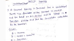
Page 21 :
PROBLEMS, M3.P1) A journal bearing whose diameter is 200 mm is subjected to a load of 50 kN, and, the shaft makes 100 RPM. Find the work lost in friction, if the coefficient of friction is 0.02., (2017 OCTOBER 6 marks), , 21
Page 23 :
PROBLEMS, M3.P2) The load on journal bearing due to the turbine shaft of 300 mm diameter is 150 kN., The shaft rotates at 1800 rpm. Determine (i) Length of bearing if allowable bearing, pressure is 1.6 MPa and (ii) Amount of heat to be removed by the lubricant, if coefficient of, friction is 0.011. (2018 APRIL 8 marks), , 23
Page 25 :
PROBLEMS cont…, M3.P3) A journal bearing whose diameter is 60 mm is subjected to a load of 4.5 kN while, rotating at 180 RPM. If coefficient of friction is 0.02 and L/D ratio is 3, Find :, (i) Beating pressure (ii) Power lost in friction (iii)Heat generated (2018 OCTOBER 8 marks), , 25
Page 27 :
PROBLEMS cont…, M3.P4) A journal bearing of diameter is 50 mm and length 100 mm is subjected to a load of, 5 kN while rotating at 800 RPM. If coefficient of friction is 0.004 , temperature of the, lubricating oil is 75C and room temperature is 35C. Find the artificial cooling required?, Assume coefficient of heat dissipated as 0.00167 kJ/min/cm2/C., , 27
Page 29 :
Coefficient of friction and Bearing Characteristic Number, for Journal Bearings, It has been shown by experiments that the coefficient of friction for a full lubricated, journal bearing is a function of the following three variables, i), , ii), , iii), , The coefficient of friction,, Where,, , 29
Page 30 :
Bearing Characteristic Number and Bearing Modulus, for Journal Bearings, The factor, number., , is known as bearing characteristic number. It is a dimensionless, , The variation of coefficient of friction with the values of bearing characteristic, number is shown below, The part of the curve PQ represents the region, of thick film lubrication. Between Q and R, the, Ratio ZN / p will reduce the film thickness so, that partial metal to metal contact will, result. The thin film or boundary lubrication or, imperfect lubrication exists between R and S., Bearing modulus is the value of ZN / p at, which minimum amount of friction occurs. In, the given figure it is denoted by the point A., The bearing modulus is denoted by letter K., , 30
Page 31 :
Coefficient of friction from Bearing Characteristic Number, for Journal Bearings, The coefficient of friction,, , 31
Page 32 :
PROBLEMS cont…, M3.P5) The load on the journal bearing is 150kN due to turbine shaft of 300 mm diameter, running at 1800 rpm. Determine the following: (i) Length of the bearing if the allowable, bearing pressure is 1.6 N/mm2, and (ii) Amount of heat to be removed by lubricant per, minute. The bearing temperature can be taken as 60°C and viscosity of the oil at 60°C is, 0.02 kg/m s and the bearing clearance is 0.25 mm.(2019 OCTOBER 8 marks), , 32
Page 34 :
Design of Thrust Bearings, Foot Step bearing, , Length of rectangular base = 3.75d, Thickness of base = 0.25d + 3, Distance between the centre of bolt holes = 2.75d, Overall height of cast iron block = 1.75d, Out side diameter of cast iron block =1.8d, Inside diameter of cast iron block or outside diameter of bush =1.3d, Out side diameter of collar =1.5d, Thickness of collar = 0.25d, 34
Page 35 :
Design of Thrust Bearings, , 35
Page 36 :
Design of Thrust Bearings, , 36
Page 37 :
Design of Thrust Bearings, , 37
Page 38 :
PROBLEMS cont…, M3.P5) A flat foot step bearing supports a shaft of 300 mm diameter, running at 150 rpm, and carrying a load of 25kN. Calculate the power lost in friction at bearing, if the coefficient, of friction is 0.05., , 38
Page 39 :
PROBLEMS cont…, M3.P6) A foot step bearing supports a shaft of 120mm diameter, running at 100 rpm. The, shaft is bored with a shallow hole of 40mm at the end. If the bearing pressure is 0.75 MPa,, 1.Find the load to be supported 2. The power lost in friction 3. the heat generated at the, bearing if the coefficient of friction is 0.015., , 39
Page 40 :
CAMS, INTRODUCTION, A cam is a rotating machine element which gives reciprocating or oscillating, motion to another element known as follower., The cams are widely used for operating the inlet and exhaust valves of internal, combustion engines, automatic attachment of machineries, paper cutting machines,, spinning and weaving textile machineries, feed mechanism of automatic lathes etc., , 40
Page 41 :
Classification of Followers, The followers are classified as given below, 1. According to the surface in contact, 2. According to the motion of the follower, 3. According to the path of motion of the follower, , According to the surface in contact, (a) Knife edge follower : When the contacting end of the follower has a sharp, knife edge, it is called a knife edge follower. The sliding motion takes place, between the contacting knife edge surface and the cam surface. It is rarely, used in practice because the small area of contacting surface results in, excessive wear. In knife edge followers, a considerable side thrust exists, between the follower and the guide., (b) Roller follower : When the contacting end of the follower is a roller, it is, called a roller follower. Since the rolling motion takes place between the, contacting roller surfaces and the cam surfaces , the rate of wear is reduced., The roller followers are extensively used in stationary gas and oil engines and, aircraft engines., 41
Page 42 :
Classification of Followers, (c) Flat faced or mushroom follower : When the contacting end of the follower, is a perfectly flat face, it is called a flat-faced follower. When the flat faced, follower is circular, it is then called a mushroom follower. The relative motion, between the contacting surfaces is largely of sliding nature but wear may be, reduced by off-setting the axis of the follower to the axis of rotation the cam., The flat faced followers are generally used where space is limited such as in, cams which operate the valves of automobile engines., (d) Spherical faced follower : When the contacting end of the follower is of, spherical shape, it is called a spherical faced follower. It may be noted that, when a flat-faced follower is used in automobile engines, high surface, stresses are produced. In order to minimize these stresses, the flat end of the, follower is machined to a spherical shape., , 42
Page 43 :
Classification of Followers, , 43
Page 44 :
Classification of Followers, According to the motion of the follower, (a) Reciprocating or translating follower : When the follower reciprocates in, guides as the cam rotates uniformly, it is known as reciprocating or translating, follower., (b) Oscillating or rotating follower : When the uniform rotary motion of the cam, is converted into predetermined oscillatory motion of the follower, it is called, oscillating or rotating follower., , 44
Page 45 :
Classification of Followers, According to the path of motion of the follower, (a) Radial follower : When the motion of the follower is along an axis passing, through the centre of the cam, it is known as radial follower., (b) Off-set follower : When the motion of the follower is along an axis away from, the axis of the cam centre, it is called off-set follower. ., , 45
Page 46 :
Classification of Cams, According to the path of motion of the follower, (a) Radial or disc cam: In radial cams, the follower reciprocates or oscillates in a, direction perpendicular to the cam axis., (b) Cylindrical cam : In cylindrical cams, the follower reciprocates or oscillates in, a direction parallel to the cam axis. The follower rides in a groove at its, cylindrical surface., , 46
Page 47 :
Terms Used in Radial Cams, 1. Base circle, , : It is the smallest circle that can be drawn to the cam profile., , 2. Trace point, , : It is a reference point on the follower and is used to generate the, pitch curve. In case of knife edge follower, the knife edge, represents the trace point and the pitch curve corresponds to the, cam profile. In a roller follower, the centre of the roller represents, the trace point., , 3. Pitch curve, , : It is the curve generated by the trace point as the follower moves, relative to the cam. For a knife edge follower, the pitch curve and, the cam profile are same whereas for a roller follower, they are, separated by the radius of the roller., , 4. Pressure angle : It is the angle between the direction of the follower motion and a, normal to the pitch curve. This angle is very important in, designing a cam profile. If the pressure angle is too large, a, reciprocating follower will jam in its bearings., 47
Page 48 :
Terms Used in Radial Cams, 5. Pitch point, , : It is a point on the pitch curve having the maximum pressure, angle., , 6. Pitch circle, , : It is a circle drawn from the centre of the cam through the pitch, points., , 7. Prime circle, , : It is the smallest circle that can be drawn from the centre of the, cam and tangent to the pitch curve. For a knife edge and a flat, face follower, the prime circle and the base circle are identical., For a roller follower, the prime circle is larger than the base circle, by the radius of the roller., , 8. Lift or stroke, , : It is the maximum travel of the follower from its lowest position, to the topmost position., , ., , 48
Page 49 :
Terms Used in Radial Cams, , 49
Page 50 :
Motion of the Follower, The cam is usually assumed to rotate with uniform speed and the motion of the, follower during a complete revolution of the cam is described by a diagram known as, displacement diagram, The maximum follower displacement from its lowest position to the topmost, position is known as the stroke or lift of the follower., When the follower is moving away from the cam shaft axis during the rotation of, cam is said to be an outstroke, and when moving in the reverse direction it is said to be, in stroke or return stroke., The angle through which the cam turns during the time of out stroke is known as, angle of ascent., In outstroke the follower rises away from the cam shaft axis and the movement of, follower marked on the displacement diagram is known as the rise part of the, displacement diagram., The angle through which the cam turns during the time of return stroke is known as, angle of descent., 50
Page 51 :
Motion of the Follower, In the return stroke the follower returns to the initial position and the movement of, the follower marked on displacement diagram is known as the return part or fall part, of the displacement diagram., The period when the follower is at rest is known as dwell period, The angle through which the cam turns while it is at rest is known as angle of dwell, or simply dwell. This part on the displacement diagram is marked as dwell., , 51
Page 52 :
Motion of the Follower, The follower, during its travel, may have one of the following motions., 1. Uniform velocity, 2. Simple harmonic motion, 3. Uniform acceleration and retardation, 4. Cycloidal motion, , 52
Page 53 :
Displacement Diagram - Follower Moves with Uniform Velocity, Since the follower moves with uniform velocity during its rise and return stroke, the, slope of the displacement curves must be constant. The curves AB1 and C1D must be, straight lines., , 53
Page 54 :
Displacement Diagram - Follower Moves with Simple Harmonic Motion, The displacement diagram is drawn as follows:, 1. Draw a semi-circle on the follower stroke as diameter., 2. Divide the semi-circle into any number of even equal parts (say eight)., 3. Divide the angular displacements of the cam during out stroke and return stroke, into the same number of equal parts., 4. The displacement diagram is obtained by projecting the points as shown in following, figure., , 54
Page 55 :
Displacement Diagram –, Follower Moves Uniform Acceleration and Retardation, Displacement diagram consists of a parabolic curve and is drawn as given below :, 1. Divide the angular displacement of the cam during outstroke ( θO ) into any even, number of equal parts (say eight) and draw vertical lines through these points as, shown in following figure., 2. Divide the stroke of the follower (S) into the same number of equal even parts., 3. Join Aa to intersect the vertical line through point 1 at B. Similarly, obtain the other, points C, D etc. as shown in figure. Now join these points to obtain the parabolic curve, for the out stroke of the follower., 4. In the similar way as discussed above, the displacement diagram for the follower, during return stroke may be drawn., , 55
Page 56 :
Construction of Cam Profile for a Radial Cam, In order to draw the cam profile for a radial cam, first of all the displacement diagram, for the given motion of the follower is drawn., Then by constructing the follower in its proper position at each angular position, the, profile of the working surface of the cam is drawn., In constructing the cam profile, the principle of kinematic inversion is used, i.e. the, cam is imagined to be stationary and the follower is allowed to rotate in the opposite, direction to the cam rotation., , 56
Page 57 :
Construction of Cam Profile for a Radial Cam, D1. A cam is to give the following motion to a knife-edged follower:, 1. Outstroke during 60° of cam rotation., 2. Dwell for the next 30° of cam rotation., 3. Return stroke during next 60° of cam rotation., 4. Dwell for the remaining 210° of cam rotation., The stroke of the follower is 40 mm and the minimum radius of the cam is 50 mm. The, follower moves with uniform velocity during both the outstroke and return strokes., Draw the profile of the cam when the axis of the follower passes through the axis of, the cam shaft., , 57
Page 58 :
Construction of Cam Profile for a Radial Cam – Displacement Diagram, First the displacement diagram is created., 1. Draw a horizontal line AX = 360° to some suitable scale. On this line, mark AS = 60°, to represent outstroke of the follower, ST = 30° to represent dwell, TP = 60° to, represent return stroke and PX = 210° to represent dwell., 2. Draw vertical line AY equal to the stroke of the follower (40 mm) and complete the, rectangle., 3. Divide the angular displacement during outstroke and return stroke into any equal, number of even parts and draw vertical lines through each point., 4. Since the follower moves with uniform velocity during outstroke and return stroke,, the displacement diagram consists of straight lines., , 58
Page 59 :
Construction of Cam Profile for a Radial Cam – Cam Profile, 1. Draw a base circle with radius equal to the minimum radius of the cam (50 mm), with O as centre., 2. Since the axis of the follower passes through the axis of the cam shaft, mark trace, point A., 3. From OA, mark angle AOS = 60° to represent outstroke, angle SOT = 30° to represent, dwell and angle TOP = 60° to represent return stroke., 4. Divide the angular displacements during outstroke and return stroke (angle AOS and, angle TOP) into the same number of equal even parts as in displacement diagram., 5. Join the points 1, 2, 3 ...etc. and 0′ ,1′ , 2′ , 3′ , ... etc. with centre O and produce, beyond the base circle ., 6. Now set off 1B, 2C, 3D ... etc. and 0′ H,1′ J ... etc. from the displacement diagram., 7. Join the points A, B, C,... M, N, P with a smooth curve. The curve AGHPA is the, complete profile of the cam., , 59
Page 60 :
Construction of Cam Profile for a Radial Cam – Cam Profile, , 60
Page 61 :
Construction of Cam Profile for a Radial Cam, D2.A cam is to give the following motion to a knife-edged follower:, 1. Outstroke during 60° of cam rotation., 2. Dwell for the next 30° of cam rotation., 3. Return stroke during next 60° of cam rotation., 4. Dwell for the remaining 210° of cam rotation., The stroke of the follower is 40 mm and the minimum radius of the cam is 50 mm. The, follower moves with uniform velocity during both the outstroke and return strokes., Draw the profile of the cam when the axis of the follower is offset by 20 mm from the, axis of the cam shaft., , 61
Page 62 :
Construction of Cam Profile for a Radial Cam – Displacement Diagram, First the displacement diagram is created., , 62
Page 63 :
Construction of Cam Profile for a Radial Cam – Cam Profile, 1. Draw a base circle with radius equal to the minimum radius of the cam ( 50 mm), with O as centre., 2. Draw the axis of the follower at a distance of 20 mm from the axis of the cam, which, intersects the base circle at A., 3. Join AO and draw an offset circle of radius 20 mm with centre O., 4. From OA, mark angle AOS = 60° to represent outstroke, angle SOT = 30° to represent, dwell and angle TOP = 60° to represent return stroke., 5. Divide the angular displacement during outstroke and return stroke (angle AOS and, angle TOP) into the same number of equal even parts as in displacement diagram., 6. Now from the points 1, 2, 3 ... etc. and 0′,1′, 2′,3′ ... etc. on the base circle, draw, tangents to the offset circle and produce these tangents beyond the base circle., 7. Now set off 1B, 2C, 3D ... etc. and 0′ H,1′ J ... etc. from the displacement diagram., 8. Join the points A, B, C ...M, N, P with a smooth curve. The curve AGHPA is the, complete profile of the cam., , 63
Page 64 :
Construction of Cam Profile for a Radial Cam – Cam Profile, , 64
Page 65 :
Construction of Cam Profile for a Radial Cam – Cam Profile, D3., , 65
Page 66 :
Construction of Cam Profile for a Radial Cam – Cam Profile, , 66
Page 67 :
Construction of Cam Profile for a Radial Cam – Cam Profile, , 67
Page 68 :
Construction of Cam Profile for a Radial Cam – Cam Profile, D4., , 68
Page 69 :
Construction of Cam Profile for a Radial Cam – Cam Profile, , 69
Page 70 :
Construction of Cam Profile for a Radial Cam – Cam Profile, , 70
Page 71 :
Construction of Cam Profile for a Radial Cam – Cam Profile, , 71
Page 72 :
72
Page 73 :
73
Page 74 :
GOVERNERS, The function of a governor is to regulate the mean speed of an engine, when there, are variations in the load., , When the load on an engine increases, its speed decreases, therefore it becomes, necessary to increase the supply of working fluid., When the load on the engine decreases, its speed increases and thus less working, fluid is required., The governor automatically controls the supply of working fluid to the engine with, the varying load conditions and keeps the mean speed within certain limits., , 74
Page 75 :
TYPES OF GOVERNORS, The governors are classified as, 1. Centrifugal governors, , 2. Inertia governors, , The centrifugal governors are further classified as follows, , 75
Page 76 :
WATT GOVERNOR, The simplest form of a centrifugal governor is a Watt governor. It is basically a, conical pendulum with links attached to a sleeve of negligible mass., The function of a governor is to regulate the mean speed of an engine, when there, are variations in the load., , 76
Page 77 :
WATT GOVERNOR, It consists of two balls of equal mass, which are attached to the arms as shown in Fig. The, balls revolve with a spindle. The upper ends of the arms are pivoted to the spindle, so that, the balls may rise up or fall down as they revolve about the vertical axis. The arms are, connected by the links to a sleeve, which is keyed to the spindle. This sleeve revolves with, the spindle, but can slide up and down. The balls and the sleeve rise when the spindle, speed increases, and falls when the speed decreases., The sleeve is connected by a bell crank lever to a throttle valve. The supply of the working, fluid decreases when the sleeve rises and increases when it falls. When the load on the, engine increases, the engine and the governor speed decreases. This results in the, decrease of centrifugal force on the balls. Hence the balls move inwards and the sleeve, moves downwards. The downward movement of the sleeve operates a throttle valve at the, other end of the bell crank lever to increase the supply of working fluid and thus the, engine speed is increased and extra power output is increased ., When the load on the engine decreases, the engine and the governor speed increases,, which results in the increase of centrifugal force on the balls. Thus the balls move, outwards and the sleeve rises upwards. This upward movement of the sleeve reduces the, supply of the working fluid and hence the speed is decreased and the power output is, reduced., 77
Page 78 :
WATT GOVERNOR, The arms of the governor may be connected to the spindle in the following three, ways,, 1. The pivot P, may be on the spindle axis as shown in Fig. (a)., 2. The pivot P, may be offset from the spindle axis and the arms when produced, intersect at O, as shown in Fig. (b)., 3. The pivot P, may be offset, but the arms cross the axis at O, as shown in Fig. (c)., , 78
Page 79 :
PORTER GOVERNOR, The function of a governor is to regulate the mean speed of an engine, when there, are variations in the load., Simple watt governor is unsuitable for high speeds and this drawback has been, overcome by loading the governor with a dead weight., The Porter governor is a modification of a Watt’s governor, with central load, attached to the sleeve as shown in Fig., , 79
Page 80 :
PORTER GOVERNOR, Porter governor is a dead weight type of centrifugal governor. It consists of two, masses called the governor balls attached to the spindle with the help of four links or, arms. The lower arms are attached to the sleeve which acts as a central weight., Governor balls are rotate at different speeds depends upon the load on the engine, about the axis of the governor shaft which is driven through suitable gearing from the, engine crankshaft., The speed of the rotation of balls increases as the load on the engine decreases., Due to the increase of speed the governor balls fly outwards and the sleeve moves, upwards thus closing the working fluid passage till the engine speed comes back to its, designed speed., On the other hand the speed of rotation of balls decreases as the load on the engine, increases and the governor balls move near to the governor axis due to reduction in the, centrifugal force on the fly balls. At that time the sleeve moves downwards thus opening, the working fluid passage more till the engine speed comes back to its designed speed ., , 80
Page 81 :
TERMS USED IN GOVERNORS, Height of a governor: It is the vertical distance from the centre of the ball to a point, where the arms (or axes of the arms) intersect on the spindle axis. It is usually denoted, by h., , Equilibrium speed: It is the speed at which the governor balls, arms etc., are in, complete equilibrium and the sleeve does not tend to move upwards or downwards., Mean equilibrium speed: It is the speed at the mean position of the balls or the, sleeve., Maximum equilibrium speed: The speed at the maximum radius of rotation of the, balls, without tending to move either way are known as maximum equilibrium speed., Minimum equilibrium speed: The speed at the minimum radius of rotation of the, balls, without tending to move either way are known as minimum equilibrium speed., Sleeve lift: It is the vertical distance which the sleeve travels due to change in, equilibrium speed., , 81
Page 82 :
TERMS USED IN GOVERNORS, Sensitiveness : For a given governor, greater the lift of the sleeve corresponding to a, given fractional change in speed, the greater is the sensitiveness of the governor., Consider two governors A and B running at the same speed. When the speed increases, or decreases by a certain amount, the lift of the sleeve of governor A is greater than the, lift of the sleeve of governor B. It is then said that the governor A is more sensitive than, the governor B., The sensitiveness is defined as the ratio of the difference between the maximum and, minimum equilibrium speeds to the mean equilibrium speed., , 82
Page 83 :
TERMS USED IN GOVERNORS, Stability: A governor is said to be stable when for every speed within the working, range there is only one radius of rotation of the governor balls at which the governor is, in equilibrium. For a stable governor, if the equilibrium speed increases, the radius of, governor balls must also increase., Hunting: A governor is said to be hunt if the speed of the engine fluctuates, continuously above and below the mean speed. This is caused by a too sensitive, governor which changes the fuel supply by a large amount when a small change in the, speed of rotation takes place. For example, when the load on the engine increases, the, engine speed decreases and, if the governor is very sensitive, the governor sleeve, immediately falls to its lowest position. This will result in the opening of the control, valve wide which will supply the fuel to the engine in excess of its requirement so that, the engine speed rapidly increases again and the governor sleeve rises to its highest, position. Due to this movement of the sleeve, the control valve will cut off the fuel, supply to the engine and thus the engine speed begins to fall once again. This cycle is, repeated indefinitely., , 83
Page 84 :
FLYWHEEL, A flywheel used in machines serves as a reservoir, which stores energy during the, period when the supply of energy is more than the requirement, and releases it during, the period when the requirement of energy is more than the supply., , When the flywheel absorbs energy, its speed increases and when it releases energy,, the speed decreases., A flywheel does not maintain a constant speed, it simply reduces the fluctuation of, speed. In other words, a flywheel controls the speed variations caused by the fluctuation, of the engine turning moment during each cycle of operation., , 84
Page 85 :
DIFFERENCES BETWEEN FLYWHEEL & GOVERNOR, , 85
Page 86 :
TURNING MOMENT DIAGRAM, The turning moment diagram is the graphical representation of the turning moment, or crank-effort for various positions of the crank., The turning moment diagram is also known as crank effort diagram., It is plotted on cartesian co-ordinates, in which the turning moment is taken as the, ordinate and crank angle as abscissa., , The area of the turning moment diagram represents the work done per revolution., , 86
Page 87 :
TURNING MOMENT DIAGRAM FOR A SINGLE CYLINDER, DOUBLE ACTING STEAM ENGINE, A turning moment diagram for a single cylinder double acting steam engine is shown, in Fig., The vertical ordinate represents the turning moment and the horizontal ordinate, represents the crank angle., , 87
Page 88 :
TURNING MOMENT DIAGRAM FOR A SINGLE CYLINDER, DOUBLE ACTING STEAM ENGINE, The turning moment (T ) is zero, when the crank angle (θ) is zero. It is maximum, when the crank angle is 90° and it is again zero when crank angle is 180°., Since the work done is the product of the turning moment and the angle turned,, therefore the area of the turning moment diagram represents the work done per, revolution., The engine is assumed to work against the mean resisting torque, as shown by a, horizontal line AF. The height of the ordinate aA represents the mean height of the, turning moment diagram., It is assumed that the work done by the turning moment per revolution is equal to, the work done against the mean resisting torque, therefore the area of the rectangle, aAFe is proportional to the work done against the mean resisting torque., When the turning moment is positive (i.e. when the engine torque is more than the, mean resisting torque) as shown between points B and C (or D and E) in Fig, the, crankshaft accelerates and the work is done by the steam., When the turning moment is negative (i.e. when the engine torque is less than the, mean resisting torque) as shown between points C and D in Fig, the crankshaft retards, and the work is done on the steam., , 88
Page 89 :
TURNING MOMENT DIAGRAM FOR A FOUR STROKE CYCLE, INTERNAL COMBUSTION ENGINE, A turning moment diagram for a four stroke cycle internal combustion engine is, shown in Fig., The vertical ordinate represents the turning moment and the horizontal ordinate, represents the crank angle., In a four stroke cycle internal combustion engine, there is one working stroke after, the crank has turned through two revolutions, i.e. 720° (or 4 π radians)., , 89
Page 90 :
TURNING MOMENT DIAGRAM FOR A FOUR STROKE CYCLE, INTERNAL COMBUSTION ENGINE, The engine is assumed to work against the mean resisting torque., It is assumed that the work done by the turning moment per revolution is equal to, the work done against the mean resisting torque, therefore the area under the mean, resistance line is proportional to the work done against the mean resisting torque., Since the pressure inside the engine cylinder is less than the atmospheric pressure, during the suction stroke, therefore a negative loop is formed as shown in Fig., , During the compression stroke, the work is done on the gases, therefore a higher, negative loop is obtained., During the expansion or working stroke, the fuel burns and the gases expand,, therefore a large positive loop is obtained. In this stroke, the work is done by the gases., During exhaust stroke, the work is done on the gases, therefore a negative loop is, formed., 90
Page 91 :
TURNING MOMENT DIAGRAM FOR A MULTI-CYLINDER ENGINE, Turning moment diagram for a compound steam engine having three cylinders and, the resultant turning moment diagram is shown in Fig., The resultant turning moment diagram is the sum of the turning moment diagrams, for the three cylinders., The vertical ordinate represents the turning moment and the horizontal ordinate, represents the crank angle., The first cylinder is the high pressure cylinder, second cylinder is the intermediate, cylinder and the third cylinder is the low pressure cylinder., The cranks, in case of three cylinders, are placed at 120° to each other., , 91
Page 92 :
FLUCTUATION OF ENERGY, The variations of energy above and below the mean resisting torque line are called, fluctuations of energy., The fluctuation of energy is determined by the turning moment diagram for one, complete cycle of operation., Consider the turning moment diagram for a single cylinder double acting steam, engine as shown in Fig., , The mean resisting torque line AF cuts the turning moment diagram at points B, C, D, and E., 92
Page 93 :
FLUCTUATION OF ENERGY, When the crank moves from a to p, the work done by the engine is equal to the area, aBp, whereas the energy required is represented by the area aABp., The engine has done less work than the requirement. This amount of energy is taken, from the flywheel and the speed of the flywheel decreases., When the crank moves from p to q, the work done by the engine is equal to the area, pBbCq, whereas the requirement of energy is represented by the area pBCq., The engine has done more work than the requirement. This excess work is stored in, the flywheel and the speed of the flywheel increases, Similarly, when the crank moves from q to r, developed work is less than required, and it is taken from flywheel and speed of the flywheel decreases., As the crank moves from r to s, excess energy is again developed and the speed of, flywheel again increases., As the crank moves from s to e, again there is a loss of work and the speed of, flywheel decreases., The variations of energy above and below the mean resisting torque line are called, fluctuations of energy., , 93
Page 94 :
FLUCTUATION OF ENERGY, The engine has a maximum speed either at q or at s. This is due to the fact that the, flywheel absorbs energy while the crank moves from p to q and from r to s., On the other hand, the engine has a minimum speed either at p or at r. The reason is, that the flywheel gives out some of its energy when the crank moves from a to p and q, to r., The difference between the maximum and the minimum energies is known as, maximum fluctuation of energy., , 94
Page 95 :
MAXIMUM FLUCTUATION OF ENERGY, The difference between the maximum and the minimum energies is known as, maximum fluctuation of energy., A turning moment diagram for a multi-cylinder engine is shown in following Fig. The, horizontal line AG represents the mean torque line. Let a1, a3, a5 be the areas above the, mean torque line and a2, a4 and a6 be the areas below the mean torque line. These, areas represent some quantity of energy which is either added or subtracted from the, energy of the moving parts of the engine., Let the energy in the flywheel at A = E, Energy at B = E + a1, Energy at C = E + a1– a2, Energy at D = E + a1 – a2 + a3, Energy at E = E + a1 – a2 + a3 – a4, Energy at F = E + a1 – a2 + a3 – a4 + a5, Energy at G = E + a1 – a2 + a3 – a4 + a5 – a6, = Energy at A, , 95
Page 97 :
COEFFICIENT OF FLUCTUATION OF ENERGY, It is defined as the ratio of the maximum fluctuation of energy to the work done per, cycle., , Work done per cycle = Tmean × θ, where, Tmean = Mean torque, θ = Angle turned (in radians), in one revolution., = 2π, in case of steam engine and two stroke internal combustion engines, = 4π, in case of four stroke internal combustion engines., , 97
Page 98 :
COEFFICIENT OF FLUCTUATION OF SPEED, The difference between the maximum and minimum speeds during a cycle is called, the maximum fluctuation of speed., The ratio of the maximum fluctuation of speed to the mean speed is called the, coefficient of fluctuation of speed., Let N1 and N2 = Maximum and minimum speeds in r.p.m. during the cycle, , Coefficient of fluctuation of speed,, , The reciprocal of the coefficient of fluctuation of speed is known as coefficient of, steadiness, 98
Page 99 :
ENERGY STORED IN A FLYWHEEL, Let, m = Mass of the flywheel in kg, k = Radius of gyration of the flywheel in m, I = Mass moment of inertia of the flywheel about its axis of rotation in kg-m2, = m.k2, N1 and N2 = Maximum and minimum speeds during the cycle in r.p.m.,, ω1 and ω2 = Maximum and minimum angular speeds during the cycle in rad/s, , Mean kinetic energy of the flywheel,, , 99