Notes of Mechanical 5th Sem, Automobile Engineering TRANSMISSION SYSTEM 1.pdf - Study Material
Page 2 :
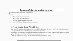
SUB-AUTOMOBILE ENGG., , TOPIC-TRANSMISSION SYSTEM, , BY ROUSHAN SIR, , INTRODUCTION TO TRANSMISSION SYSTEM :, TYPES OF TRANSMISSION SYSTEM, CLUTCH, GEAR BOX, PROPEELER SHAFT, UNIVERSAL JOINTS, Final drive and differential, REAR AXLE, , Defination of Automoble Transmission- The mechanism that transmits the power developed by the, engine of automobile to the engine to the driving wheels is called the TRANSMISSION SYSTEM (or, POWER TRAIN)., It is composed of –, 1. Clutch, 2. The gear box, 3. Propeller shaft, 4. Universal joints, 5. Rear axle, 6. Wheel, 7. Tyres, Diagram of automobile transmission system, , [Date], , 1
Page 3 :
SUB-AUTOMOBILE ENGG., , TOPIC-TRANSMISSION SYSTEM, , BY ROUSHAN SIR, , Requirements Of Transmission System : Provide means of connection and disconnection of engine with rest of power train without shock and, smoothly., Provide a varied leverage between the engine and the drive wheels Provide means to transfer, power in opposite direction., Enable power transmission at varied angles and varied lengths., Enable speed reduction between engine and the drive wheels in the ratio of 5:1., Enable diversion of power flow at right angles, . Provide means to drive the driving wheels at different speeds when required., Bear the effect of torque reaction , driving thrust and braking effort, , CLUTCH, A clutch is a mechanism which enables the rotary motion of one shaft to be transmitted at will to second, shaft ,whose axis is coincident with that of first., Clutch is located between engine and gear box. When the clutch is engaged, the power flows from the, engine to the rear wheels through the transmission system and the vehicle moves . when the clutch is, disengaged ,the power is not transmitted to the rear wheels and the vehicle stops, while the engine is, still running., , Clutch is disengaged when, a) Starting the engine,, b) Shifting the gears,, c) Idling the engine, , Function Of a Clutch :, a) To permit engagement or disengagement of a gear when the vehicle is stationary and the engine is, running, b) To transmit the engine power to the road wheels smoothly without shock to the transmission system, while setting the wheel in motion., c) To permit the engaging of gears when the vehicle is in motion without damaging the gear wheels., , [Date], , 2
Page 4 :
SUB-AUTOMOBILE ENGG., , TOPIC-TRANSMISSION SYSTEM, , BY ROUSHAN SIR, , Principle Of Operation Of a Clutch, , The clutch principle is based on friction . when two friction surface are brought in contact with each, other and pressed they are united due to friction between them. If one is revolved the other will also, revolve . The friction between the two surfaces depends upon, i., ii., iii., , Area of the surface,, Pressure applied upon them,, Coefficient of friction of the surface materials, , Here , One surface is considered as driving member and the other as driven member., The driving member of a clutch is the flywheel mounted on the crankshaft, the driven member is, the pressure plate mounted on the transmission shaft . Friction surfaces (clutch plates ) are between, the two members (driving and driven). On the engagement of the clutch, the engine is connected to, the transmission (gear box) and the power flows from the engine to the rear wheels through the, transmission system . when the clutch is disengaged by pressing a clutch pedal, the engine is, disconnected from the transmission and consequently the power does not flow to the rear wheels, while the engine is still running., , [Date], , 3
Page 5 :
SUB-AUTOMOBILE ENGG., , TOPIC-TRANSMISSION SYSTEM, , BY ROUSHAN SIR, , Diaphragm Spring Clutch, , [Date], , 4
Page 6 :
SUB-AUTOMOBILE ENGG., , TOPIC-TRANSMISSION SYSTEM, , BY ROUSHAN SIR, , A diaphragm spring type clutch is shown in fig. where shows the clutch in the engaged, position and in the disengaged position. It is seen from the above figures that the diaphragm, spring is supported on a fulcrum retaining ring so that any section through the spring can be, regarded as a simple lever. The pressure plate E is movable axially, but it is fixed radically, with respect to the cover. This is done by providing a series of equally spaced lugs cast upon, the back surface of the pressure plate. The drive from the engine flywheel is transmitted, through the cover, pressure plate and the friction plate to the gear box input shaft. The, clutch is disengaged by pressing the clutch pedal which actuates the release fingers by means, of a release ring. This pivots the spring about its fulcrum, relieving the spring load on the, outside diameter, thereby disconnecting the drive., , When the pedal is depressed the linkage moves release bearing towards the, flywheel to disengage the clutch. As the bearing contacts with inner position of the, conical springs it moves that position forward which cause the link to move, backward. This removes the pressure on the pressure plate and release the clutch, plate from contact with other driving members., , Advantages Of Diaphragm Clutch :, , It is more compact by means of storing energy. Thus compact design results in smaller, clutch housing., , , , Diaphragm spring is less affected by centrifugal forces., , , , In Diaphragm spring the load deflection curve is not linear, therefore in this case the clutch, facing wears the pressure by diaphragm spring gradually increases., , , , The diaphragm spring acts as both, the clamping spring as well as the release lever. So, many parts like struts, eye bolts, levers etc., , Disadvantages Of Diaphragm Clutch :, , To get more co-efficient of friction, the size and diameter of Diaphragm is increased., , , , Compare to Diaphragm spring, Coil springs have tendency to distort in the transverse, direction at higher speeds., , [Date], , 5
Page 7 :
SUB-AUTOMOBILE ENGG., , TOPIC-TRANSMISSION SYSTEM, , BY ROUSHAN SIR, , Introduction to Single Plate Clutch, Clutch lies in between the flywheel the gearbox, allows the engine power to be, disconnected from the transmission to free it from the torque (turning effort) when, gears are engaged or changed., , Single plate Clutch is the most common type of clutch used in motor, vehicles. It consists of only one clutch plate, mounted on the splines of the, clutch shaft., The flywheel is mounted on the engine crankshaft and rotates with it. The, pressure plate is bolted to the flywheel through clutch springs and is free to, slide on the clutch shaft when the clutch pedal is operated., When the clutch is engaged the clutch plate is gripped between the flywheel and, the pressure plate. The friction linings are on both sides of the clutch plate., Due to the friction between the flywheel, clutch plate and pressure plate, the clutch, plate revolves with the flywheel. As the clutch plate revolves, the clutch shaft also, revolves., [Date], , 6
Page 8 :
SUB-AUTOMOBILE ENGG., , TOPIC-TRANSMISSION SYSTEM, , BY ROUSHAN SIR, , Single plate Clutch Working :, A single disc or plate clutch as shown in figure, consist of a clutch plate, whose both sides are faced with the friction material (usually ferrodo). It is, mounted on the hub which is free to move axially along the splines of the, driven shaft. The pressure plate is mounted inside the clutch body which is, bolted to the flywheel. Both the pressure plate and the flywheel rotate with, the engine crankshaft or the driving shaft. The pressure plate pushes the, clutch plate towards the flywheel by a set of strong spring which are, arranged radially inside the body. The three levers (also known as release, levers or fingers) are carried on the pivots suspended from the case of the, body. These are arranged in such a manner so that the pressure plate, moves away from the flywheel by the inward movement of a thrust bearing., The bearing is mounted upon the forked shaft and moves forward when the, clutch pedal is pressed., , Disengaging the clutch:, When the clutch pedal is pressed down, it’s linkage forces the thrust bearing, to move towards the flywheels and pressing the pressure plate away from, the flywheel thereby the compression springs are compressed. This action, removes the pressure from the clutch plate and the driving shaft comes to a, stationary position., , Engaging the clutch:, On the other hand, when the foot is taken off from the clutch pedal, the, thrust bearing moves back by levers this action allows the springs to extend,, and thus the pressure plate pushes the clutch plate back towards the, flywheel. The clutch is, engaged and power is transmitted from engine to gearbox., , Difference Between Single Plate Clutch and Multi -Plate Clutch :, Sr., no., , Single Plate clutch, , Multi-plate clutch, , 1., , It consists of only one clutch plate., , It consists of two or more number of clutch plates., , 2., , The number of pairs of friction surfaces in, contact are two., , The number of pairs of friction surfaces in contact are, than two., , [Date], , 7
Page 9 :
SUB-AUTOMOBILE ENGG., , TOPIC-TRANSMISSION SYSTEM, , BY ROUSHAN SIR, , Sr., no., , Single Plate clutch, , Multi-plate clutch, , 3., , It does not ensure smooth engagement., , It ensures a smooth and gradual engagement., , 4., , It requires more space., , It requires less space., , 5., , For the same power transmission, larger in, size., , For the same power transmission, smaller in size., , 6., , For the same size, torque transmission, capacity is less., , For same size, torque transmission capacity is, more., , 7., , Frictional power loss is less., , Since it has number of friction plates instead of single,, frictional power loss is more., , 8., , Application- Trucks, Jeeps, cars etc., , Application- Two-wheelers, racing cars, some heavy-d, trucks., , Advantages of Single Plate Clutch :, Single plate clutch advantages are as follows :, 1. Single plate clutch is smooth in operation i.e engagement and disengagement of, clutch is smooth., 2. Very less slip occurs in its operation. Slip only occurs during the engagement of, clutch and after that no slipping occurs and functioning becomes very smooth., 3. Very less heat is generated as only one clutch plate is used., 4. The operation in this type of clutch is very fast., 5. It makes easy to change gears than a cone type., 6. It is reliable than a cone clutch., , Disadvantages of Single Plate Clutch :, Single plate clutch disadvantages are as follows :, 1. It requires more force to release., 2. The space required to accommodate the clutch is more as compared to the, multi-plate clutch., , [Date], , 8
Page 10 :
SUB-AUTOMOBILE ENGG., , TOPIC-TRANSMISSION SYSTEM, , BY ROUSHAN SIR, , 3. The capacity of torque transmission is less., 4. The size of this clutch is big even for less torque transmission., 5. Chance of tear wear is high in single plate clutches., , Applications Of Single Plate Clutch :, Single plate clutch applications are as follows :, 1. Single plate clutches are used in Buses, Trucks, and cars, etc. ( Ashok Leyland. ,, Flat – 1100, Truck ), 2. Single plate clutches used where large radial space is available., 3. As sufficient surface area is available for the heat dissipation in Single plate, clutches, no cooling oil is required. Therefore, single plate clutches are dry type., , Clutch Parts :, In general, a Clutch consists of three members, and those are:, , , Driving Members, , , , Driven Members, , , , Operating Members, , Driving members:, It is consists of a flywheel mounted on the engine crankshaft. The flywheel is, bolted to a cover that carries a pressure plate or driving disc, pressure, springs, and release levers. Thus the entire assembly of the flywheel and the, cover rotate all the time. The clutch housing and the cover provided with, openings dissipate the heat generated by the friction during the clutch, operation., , (i) Flywheel:, The flywheel is the mounting surface for the clutch. The flywheel rotates as, the engine crankshaft rotates. The friction or pressure plate bolts to the, flywheel face. The clutch disc is clamped and held against the flywheel by, the spring action of the pressure plate. The face of the flywheel is precision, machined to a smooth surface. The face of the flywheel that touches the, clutch disc is made of iron. Even if the flywheel were aluminum, the face is, [Date], , 9
Page 11 :
SUB-AUTOMOBILE ENGG., , TOPIC-TRANSMISSION SYSTEM, , BY ROUSHAN SIR, , iron because it wears well and dissipates heat better. A pilot bearing or bush, bearing supports the spigot end of the clutch shaft which is also housed in, the flywheel. It is also the second driving member., , (ii) Pilot Bearing:, The pilot bearing or bushing is pressed into the end of the crankshaft to, support the end of the transmission input shaft. The pilot bearing is a solid, bronze bushing, but it also may be a roller or ball bearing. The end of the, transmission input shaft has a small journal machined on its end. This, journal slides inside the pilot bearing. The pilot bearing prevents the, transmission shaft and clutch disc from wobbling up and down when the, clutch is released. It also assists the input shaft center of the disc on the, flywheel., , Driven members:, It is consists of a disc or plate, called the clutch plate. It is free to slide, lengthwise on the splines of the clutch shaft. It carries friction materials on, both of its surfaces. When it gripes between the flywheel and the pressure, plate, it rotates the clutch shaft through the splines., , Pressure clutch plate :, Constructional details, , clutch plate, It consists of a steel plate with a splined central hub. Annular friction facing, , [Date], , 10
Page 12 :
SUB-AUTOMOBILE ENGG., , TOPIC-TRANSMISSION SYSTEM, , BY ROUSHAN SIR, , is attached to the steel plates by rivets. Special resins are also used to bind, the friction facing. The curved cushioning spring segments are attached, rigidly to the center plate and friction facings are riveted to these springs., Centre hub-assembly consists of a splined hub with radially placed slots in, the flange of the hub. There are similar types of slots in each of the two, plates situated on either side of the hub flange., Different materials used for clutch lining:, Material:1. Leather, 2. Cork, 3. Fabric, 4. Asbestos, 5. Reybestos and Ferodo, 6. Non- asbestos clutch lining material, Necessity:1. It should, 2. It should, 3. It should, 4. It should, , have a good anti-fading characteristic, have a longer life., be nonpolluting., have a lesser cost, , Types of Single Plate Clutch:, , , Coil Spring Type Single Plate Clutch, , , , Diaphragm Spring Type Single Plate Clutch, , GEAR BOX, Necessity of Gear Box, 1. The gear box is necessary in the transmission system to maintain engine speed at the most, economical value under all conditions of vehicle movement. An ideal gear box would provide an infinite, range of gear ratios, so that the engine speed should be kept at or near that the maximum power is, developed what ever the speed of the vehicle, , [Date], , 11
Page 13 :
SUB-AUTOMOBILE ENGG., , TOPIC-TRANSMISSION SYSTEM, , BY ROUSHAN SIR, , 2. The purpose of gear box is to provide high torque at the time of starting, hill climbing, accelerating, and pulling a load. The vehicle will have to face the resistances like wind resistance, gradient resistance, and rolling resistance., , Function of Gear Box, • Torque ratio between engine and wheel to be varied for rapid acceleration and for climbing gradient., • The transmission also provides a neutral position so that the engine & the road wheels are, disconnected even with the clutch in the engaged position., • A means to back the car by reversing the direction of rotation of the drive is also provided by the, transmission., , Resistance to Motion of Vehicle, Total resistance to the vehicle motion consists of:, (i) Resistance due to wind: this is taken to be proportional to the square of the vehicle speed., (ii) Resistance due to gradient: this remains constant at all speeds. This is the component of the vehicle, weight parallel to the plane of the road., (iii) Miscellaneous: apart from the above two types various other factors also contribute towards the, vehicles resistance. These are: type of the road, tyre friction etc, , [Date], , 12
Page 14 :
SUB-AUTOMOBILE ENGG., , TOPIC-TRANSMISSION SYSTEM, , BY ROUSHAN SIR, , [Date], , 13
Page 15 :
SUB-AUTOMOBILE ENGG., , TOPIC-TRANSMISSION SYSTEM, , BY ROUSHAN SIR, , [Date], , 14
Page 16 :
SUB-AUTOMOBILE ENGG., , TOPIC-TRANSMISSION SYSTEM, , BY ROUSHAN SIR, , [Date], , 15
Page 17 :
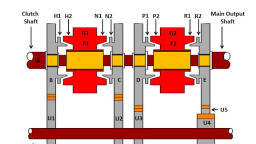
SUB-AUTOMOBILE ENGG., , TOPIC-TRANSMISSION SYSTEM, , BY ROUSHAN SIR, , Constant Mesh Gearbox, , Working:, Forward gear selection:, From the input shaft, the power starts flowing and is divided into four parts. Each part goes to one of the, output gears, namely first, second, third and fourth. Gear ratios can be obtained for each of them. This, can be done by the proper sliding of dog clutch over the teeth of the selected gearwheel. After this the, path of the energy flow completes. This happens due to the locking movement of the output shaft., , Reverse gear selection:, The power will flow from the input shaft to the reverse gears. The power is then transmitted from, the reverse gear to the reverse idler. The idler wheel will change the direction of the rotation. In, the case of forwarding direction gear selection, the output gears will rotate in a direction opposite, to the input gears. But in the case of reverse gear selection, the rotation is in the same direction as, the input shaft., , [Date], , 16
Page 18 :
SUB-AUTOMOBILE ENGG., , TOPIC-TRANSMISSION SYSTEM, , BY ROUSHAN SIR, , The steps are taken to change any gear in the constant mesh gearbox system:, 1. The first step when one wants to modify the gear would be the pressing of the clutch. After this, comes the neutral state of the vehicle to be achieved. Proper optimization of the engine’s speed is, required., 2. After the neutral gear, one moves forward to the first gear. The first gear. This process is known, as double clutching. Inefficiency in performing the above steps might lead to a harsh., , , , , , , , , , Advantages:, The first and foremost benefit of the constant gear mesh is the utilization of helical gears. The, double helical gears and the helical gears are extremely beneficial owing to their quieter, operating capabilities, There are various conditions which might cause harm. In the case of constant mesh gearbox, any, harm is suffered entirely by the dog clutch teeth. The teeth belonging to the gear wheels remain, intact. This is not the case for sliding mesh gear box., The other gear boxes are noisy and create an unwanted noice., Disadvantages:, It is less efficient than the others due to higher mesh teeth. Skill is required for it., The double clutch mesh is required. This is required to have the spinning movements of the, shaft., , Synchromesh Gear Box, This type of gearbox is similar to the constant mesh type in that all the gears on, the main shaft are in constant mesh with the corresponding gears on the layshaft., The gears on the layshaft are fixed to it while those on the main shaft are free to, rotate on the same. Its working is also similar to the constant mesh type, but in the, former, there is one definite improvement over the latter. This is the provision of a, synchromesh device which avoids the necessity of double-declutching. The parts, which ultimately are to be engaged are first brought into frictional contact which, equalizes their speed, after which these may be engaged smoothly., , [Date], , 17
Page 19 :
SUB-AUTOMOBILE ENGG., , TOPIC-TRANSMISSION SYSTEM, , BY ROUSHAN SIR, , Working of Synchromesh Gearbox :, To obtain low gear, member F2 moves towards the left which causes the friction, contact between the cone-shaped surface of gear D and member F2. The friction or, rubbing makes the speed equal then member G2 override to the left to engage with, teeth K2 and low gear is obtained. Similarly, when member F2 slides toward the, right, mesh with gear E, a reverse gear is obtained. Similarly for second gear the, member F1 and G1 are slides to the right so that finally the internal teeth on G1, have engaged with L1 then the drive to the main shaft from gear B – U1 – U2 –, gear C – G1 – F1 to spline. A direct gear is obtained by sliding member F1 toward, left., , Advantages Of Synchromesh Gearbox :, 1) No need of double-declutching as in case of constant mesh gearbox., 2) Smooth engagement of higher gears due to the synchromesh device., 3) Less noisy as helical gears are used., 4) Less vibration., , Disadvantages of Synchromesh Gearbox :, Demerits of synchromesh gearbox:, 1) Synchromesh is a finely machined element and hence is costly., , [Date], , 18
Page 20 :
SUB-AUTOMOBILE ENGG., , TOPIC-TRANSMISSION SYSTEM, , BY ROUSHAN SIR, , 2) The service of gears and synchromesh device is difficult., 3) More space is required., 4) Use of synchromesh device for low-speed gears is uneconomical., , Application of synchromesh gearbox, Modern cars, Sport utility vehicles, for Higher gears in the gearbox, , , , Difference Between Constant mesh gearbox and synchromesh gearbox, Sr., no., , Constant mesh gear box, , Synchromesh gear box, , 1., , It has need of double-declutching., , No need of double-declutching as in case of co, mesh gearbox., , 2., , The problem in the engagement of higher gears due to, constant mesh devices., , Smooth engagement of higher gears due to, synchromesh device., , 3., , It is more noisy., , It is less noisy as helical gears are used., , 4., , It has more vibration., , It has less vibration., , Epicyclic Gearbox, An Epicyclic gearbox is an automatic type gearbox in which parallel shafts and, gears arrangement from manual gear box are replaced with more compact and, more reliable sun and planetary type of gears arrangement and also the manual, clutch from manual power train is replaced with hydro coupled clutch or torque, convertor which in turn made the transmission automatic., , [Date], , 19
Page 21 :
SUB-AUTOMOBILE ENGG., , TOPIC-TRANSMISSION SYSTEM, , BY ROUSHAN SIR, , Epicyclic Gearbox Parts :, The three basic components of the epicyclic gear are:, 1. Sun: The central gear, 2. Planet carrier: Holds one or more peripheral planet gears, of the same, size, meshed with the sun gear, 3. Annulus or Ring Gear: An outer ring with inward-facing teeth that mesh, with the planet gear or gears, In many epicyclic gearing systems, among the three basic components, one, component is held stationary; one component is input, provide power to the system, and last component is output, receive the power from the system. The ratio of input, rotation to output rotation is dependent upon the number of teeth in each gear, and, upon which component is held stationary., , Construction of epicyclic Gearbox:, In the epicyclic gearbox, the epicyclic gear train is a very general term. Basically, it, involves 3 gears: a sun gear, a planet gear and a ring gear, the underlying concept, being many gear ratios can be obtained from a small volume as compared to other, types of gear trains which take up more space. Unlike simple gear trains, an, epicyclic gear train requires defining more than one input to obtain a specific, output, hence making the analysis a little difficult and non-intuitive., , [Date], , 20
Page 22 :
SUB-AUTOMOBILE ENGG., , TOPIC-TRANSMISSION SYSTEM, , BY ROUSHAN SIR, , Working of epicyclic gearbox :, The working principle of the epicyclic gearbox is based on the fact the fixing any of, the gears i.e. sun gear, planetary gears, and annular gear is done to obtain the, required torque or speed output. As fixing any of the above causes the variation in, gear ratios from high torque to high speed. So let’s see how these ratios are, obtained, , First gear ratio:, This provide high torque ratios to the vehicle which helps the vehicle to move from, its initial state and is obtained by fixing the annular gear which in turn causes the, planet carrier to rotate with the power supplied to the sun gear., , Second gear ratio:, This provides high-speed ratios to the vehicle which helps the vehicle to attain, higher speed during a drive, these ratios are obtained by fixing the sun gear which, in turn makes the planet carrier the driven member and annular the driving, member in order to achieve high-speed ratios., , Reverse gear ratio:, This gear reverses the direction of the output shaft which in turn reverses the, direction of the vehicle, this gear is achieved by fixing the planet gear carrier which, in turn makes the annular gear the driven member and the sun gear the driver, member., , One situation is when the planetary carrier is held stationary, and the sun gear is, used as input. In this case, the planetary gears simply rotate about their own axes, at a rate determined by the number of teeth in each gear. If the sun gear has S, teeth, and each planet gear has P teeth, then the ratio is equal to -S/P. This, rotation of the planet gears can inturn drive the annulus, in a corresponding ratio., If the annulus has P teeth, then the annulus will rotate by P/A turns for each turn of, the planet gears., , Advantages of Epicyclic Gearbox :, The planetary gearbox offers a set of distinct advantages which makes it an, interesting alternative to traditional gear types such as helical and parallel shaft, gearboxes in applications requiring:, , , High reduction ratios, , , , Compact and lightweight with high torque transmission, , , , High radial loads on the output shaft, , , , It is quieter in operation, [Date], , 21
Page 23 :
SUB-AUTOMOBILE ENGG., , TOPIC-TRANSMISSION SYSTEM, , BY ROUSHAN SIR, , , , Uniform distribution of load over all gears having greater tooth contact., , , , All gears are constantly in mesh, so a change of one gear to another is possible, without any loss., , Disadvantages of planetary gear systems, • Complexity, • Assembly of gears is limited to specific teeth per gear ratios, • Efficiency calculations are difficult, • Driver and driven equipment must be in line to avoid additional gearing, , Application of Epicyclic Gear train :, , , A good example of the everyday application of a planetary gear system is the, automatic transmission, of, a, car., , , , The epicyclic gear trains are used in the back gear of lathe, differential gears of, the automobiles, hoists, pulley blocks, wrist watches, etc., , , , The epicyclic gear trains are useful for transmitting high-velocity ratios with, gears of moderate size in a comparatively lesser space., , Final drive:, Final drive is a gear reduction unit in the power trains between the differential and the, drive wheels. Final drive transmits the power finally to the rear axle and the wheels., , [Date], , 22
Page 24 :
SUB-AUTOMOBILE ENGG., , TOPIC-TRANSMISSION SYSTEM, , BY ROUSHAN SIR, , [Date], , 23
Page 25 :
SUB-AUTOMOBILE ENGG., , TOPIC-TRANSMISSION SYSTEM, , BY ROUSHAN SIR, , [Date], , 24
Page 26 :
SUB-AUTOMOBILE ENGG., , TOPIC-TRANSMISSION SYSTEM, , BY ROUSHAN SIR, , [Date], , 25
Page 27 :
SUB-AUTOMOBILE ENGG., , TOPIC-TRANSMISSION SYSTEM, , BY ROUSHAN SIR, , [Date], , 26
Page 28 :
SUB-AUTOMOBILE ENGG., , TOPIC-TRANSMISSION SYSTEM, , BY ROUSHAN SIR, , [Date], , 27
Page 29 :
SUB-AUTOMOBILE ENGG., , TOPIC-TRANSMISSION SYSTEM, , BY ROUSHAN SIR, , [Date], , 28
Page 30 :
SUB-AUTOMOBILE ENGG., , TOPIC-TRANSMISSION SYSTEM, , BY ROUSHAN SIR, , [Date], , 29
Page 31 :
SUB-AUTOMOBILE ENGG., , TOPIC-TRANSMISSION SYSTEM, , BY ROUSHAN SIR, , [Date], , 30
Page 32 :
SUB-AUTOMOBILE ENGG., , TOPIC-TRANSMISSION SYSTEM, , BY ROUSHAN SIR, , [Date], , 31
Page 33 :
SUB-AUTOMOBILE ENGG., , TOPIC-TRANSMISSION SYSTEM, , BY ROUSHAN SIR, , WHAT IS DIFFERENTIAL?, The differential allows each rear wheel to turn at different speeds. During cornering but, at the same time, it gives equal torque to each wheel when both wheels have the same, traction. A system of gears in the differential arrange in such a way that it connects the, propeller shaft to the rear axle. The difference in a word intends to provide relative, movement to rear wheels., NEED OF DIFFERENTIAL, The differential allows the non-steering wheels to rotate at different speeds so the car, can corner without putting undue wear on the tires. The wheel on the inside of a turn, moves a shorter distance compared to the outer wheel. If the axle does not allow the, wheels to turn independently of each other, the tire of one wheel will be pulled across, the ground., COMPONENTS OF DIFFERENTIAL, 1. Drive pinion or Bevel pinion, , [Date], , 32
Page 34 :
SUB-AUTOMOBILE ENGG., 2., 3., 4., 5., 6., 7., , TOPIC-TRANSMISSION SYSTEM, , BY ROUSHAN SIR, , Ring gear or Crown wheel, Differential case, Differential side gear or Sun gears, Differential pinions or Planet gears, Axle shafts or Half shafts, Pinion shaft or Cross pin or spider, , CONSTRUCTION OF DIFFERENTIAL, , The figure shows the basic parts of the differential used in rear-wheel-drive cars. A, small bevel gear called differential side gear is mounted on the inner ends of each axle., Two bevel gears are placed together to connect both driving and driven shafts at an, [Date], , 33
Page 35 :
SUB-AUTOMOBILE ENGG., , TOPIC-TRANSMISSION SYSTEM, , BY ROUSHAN SIR, , angle of 90°. The differential case is connected with two-wheel axles and differential, side gears., The differential case has bearings that rotate two axle shafts. Then, two pinion gears, and their supporting shaft called pinion shaft, fit to the differential case. Then, the pinion, shaft meshes with two differential side gears connected to the inner ends of the axle, shafts., The ring gear moves to a flange on the differential case. The ring gear rotates the, differential case. Finally, the drive pinion mounts. The drive pinion assembles with, the differential housing called differential case or carrier. The driver shaft connects to, the drive pinion by a universal joint and it meshes with a ring gear. Therefore, the drive, pinion rotates when the driver turns the shaft. Thus, the ring gear rotates., , Working of differential gearbox :, 1. When Running Straight:, When the vehicle moves in a straight line, the power comes from the propeller shaft, to the bevel pinion which drives the crown wheel. Then it is carried to the, differential cage in which a set of planet pinions and sun gears are located. From, the sun gear it is transmitted to the road wheels through-axle half shafts. In this, case, the crown wheel, differential cage, planet pinions, and sun gears all turn as a, single unit and there is no relative motion between the sun gear and planet pinion., The planet pinions do not rotate about their own axis. The road wheels, half shafts,, and sun wheels offer the same resistance to being turned and the differential, gearing does not therefore operate. Both the road wheels turn at the same speed., , 2. When taking a turn:, When the vehicle takes a turn, the inner wheel experiences resistance and tends to, rotate in the opposite direction. Due to this the planet pinions start rotating about, their own axis and around the sun gear and transmit more rotary motion to the, outer side sun gear. So that outer sun gear rotates faster than the inner sun gear., Therefore the outer road wheel runs faster than the inner road wheel and covers a, more distance., , Advantages of Differential Gearbox :, 1), 2), 3), 4), , Both, Both, Both, Both, , driving, driving, driving, driving, , wheels, wheels, wheels, wheels, , can, can, can, can, , rotate, rotate, rotate, rotate, , in, in, in, in, , the, the, the, the, , same direction at the same speed., same direction at different speeds., opposite direction at the same speed., opposite direction at a different speed, , [Date], , 34
Page 36 :
SUB-AUTOMOBILE ENGG., , TOPIC-TRANSMISSION SYSTEM, , BY ROUSHAN SIR, , Propeller Shaft, The component which is used to transfer torque from the gearbox to the rear axle or, differential is called a propeller shaft. It is not only used in cars but is also used in boats and, aeroplanes. It is also known as the Cardan shaft or drive shaft., The propeller shaft is a hollow tube-like structure with a combination of universal and slip spline, joints. In most cars except the modern-day cars, the engine is situated at the front end and it is, used to drive the rear wheels., , Construction or Parts of Propeller Shaft:, A propeller shaft consists of three main components:, 1. Universal joints, 2. Split spline joints and, 3. Tubular shafts, , Universal joint:, A universal joint is the most important component of a propeller shaft there are two, universal joints in a single-piece propeller shaft. The number of universal joints can be, up to three or four depending on the type of propeller shaft., A universal joint is that component that allows rotation of the propeller shaft on various, axis. It is a flexible joint that compensates for the elevation difference between the, gearbox output shaft and the differential., , Slip spline joint:, A slip spline joint is generally used at the output side of the propeller shaft. It helps in, torque transmission at various lengths of the propeller shaft. It comes in action during, the obstacles faced by the automobile., For example, when a car approaches a speed breaker the rear wheels will be pushed, up this results in compression of the propeller shaft as soon as the car passes the, breaker the dampers push back the rear wheel which results in the normal length of the, shaft., To transmit power during such conditions a slip spline joint is used. It also protects the, shaft from compressive and tensile stresses., , Tubular shaft:, The tubular shafts are used to compensate for the distance factor between the gearbox, and the rear axle. There can be two or more tubular shafts depending on the type of, propeller shaft., , [Date], , 35
Page 37 :
SUB-AUTOMOBILE ENGG., , TOPIC-TRANSMISSION SYSTEM, , BY ROUSHAN SIR, , The tubular shafts can be short as well as long depending on the distance from the, gearbox to the axle. In the case of a rear-wheel drive, long tubular shafts are used and, in the case of a front-wheel drive, short tubular shafts are used., https://youtu.be/y8QaD8NJLxM - video, https://youtu.be/OezhCX4WBLs- video, , Advantages of Propeller shafts:, Following advantages of Propeller shaft:, , , Low or no power losses., , , , The weight of the shaft is less due to the tubular structure., , , , Construction is not very complex., , , , Ensures safe power transmission., , , , Low noise at high torques., , , , It is durable., , Disadvantages of Propeller shaft:, Following disadvantages of Propeller shaft:, , , May damage if the RPM is too high., , , , Hollow propeller shafts are costly., , , , They are not very strong, , , , Not suitable to counter bending forces., , , , There may be an oil leakage problem at the spline., , Applications of Propeller shafts:, Following application of Propeller shaft:, , , Propeller shafts are used in constructional motor vehicles., , , , They are also used in various heavy-duty machines., , , , Propeller shafts are widely used in commercial automobiles., , , , It is also used in ships for providing power to the propeller., , , , It was also used in old airplanes., , AXLE, [Date], , 36
Page 38 :
SUB-AUTOMOBILE ENGG., , TOPIC-TRANSMISSION SYSTEM, , BY ROUSHAN SIR, , An axle or axletree is a central shaft that rotates the wheels and, supports the weight of your vehicle. Axles are essential components of, any vehicle and come in three main types: front, rear, and stub., On wheeled vehicles, the axle may be fixed to the wheels, rotating, with them, or fixed to the vehicle, with the wheels rotating around the, axle. In the former case, bearings or bushings are provided at the, mounting points where the axle is supported., , Types Of Axle, Axles come in three standard types:, 1. Rear axle: This axle is responsible for the power supply to the, drive wheels. It comes in two halves, called half-waves, which are, connected by the differential. In most cases, the rear axles are, under tension, meaning that they rotate with the vehicle’s wheels., 2. Front axle: This axle is located in the front of the vehicle and is, responsible for assisting in steering and processing bumps on, uneven road surfaces. They consist of four main parts: the beam,, the swivel pin, the tie rod and the stub axle. The front axles must, be as robust as possible. That is why they are usually made of, carbon steel or nickel steel., 3. Stub Axle: Stub axles are attached to the vehicle’s front wheels,, with kingpins connecting these axles to the front axle, , Types of Rear axles, Depending upon the methods of supporting the rear axles and mounting the rear, wheels, the three types of rear axles are as follows:, 1. Semi-floating axle, 2. Full-floating axle, 3. Three quarter floating axle, , [Date], , 37
Page 39 :
SUB-AUTOMOBILE ENGG., , TOPIC-TRANSMISSION SYSTEM, , BY ROUSHAN SIR, , Semi-Floating Axle, , A semi-floating axle has a bearing located on the axle and inside the axle casing., It has to support all the loads as listed above. Therefore, it needs to be of a larger, size, for the same torque output, than any other type. The inner end of the axle is, supported by the differential side gear., , It is thus relieved of the job of carrying the weight of the car by the axle housing., The outer end has to support the weight of the car and take end thrust. The inner, end of the axle is splined to the differential side gear., The outer end is flanged so that the wheel can be bolted directly to it. In some, design, the hub of the wheel is keyed to the outer end of the axle. The vehicle load, is transmitted to the axle through the casing and the bearing, which causes the, bending or shearing of the axle. The semi-floating axle is the simplest and, cheapest of all other types and widely used on cars., , Full-Floating Axle, A full floating axle has two deep groove ball or taper roller bearings, located, between the axle casing and wheel hub. The outer of an axle is made flanged to, which the wheel hub is bolted. The axle is not supported by bearing at either end,, and its position is maintained by the way that it is supported at both ends., , [Date], , 38
Page 40 :
SUB-AUTOMOBILE ENGG., , TOPIC-TRANSMISSION SYSTEM, , BY ROUSHAN SIR, , Thus the axle is relieved of all strain caused by the weight of the vehicle on the, end thrust. It transmits only the driving torque. For this reason, it is called full, floating. The axle may be removed from the housing without distributing the wheel, by removing the nuts., An additional advantage of this design is the ability to the vehicle even if it has a, broken axle. This type of axle is more, expensive and heavier than the other axle., It is usually fitted on commercial vehicles, , Three-Quarter Floating Axle, This type of axle has a bearing placed between the hub and the axle casing. Thus,, the weight of the vehicle is transferred to the axle casing, and only the side thrust, and driving torque are taken by the axle., , [Date], , 39
Page 41 :
SUB-AUTOMOBILE ENGG., , TOPIC-TRANSMISSION SYSTEM, , BY ROUSHAN SIR, , The axle is keyed rigidly to the hub, thus proving the driving connection and, maintaining the alignment of the wheel. The inner end of this axle has the same, construction as that of the semi-floating axle. Although the three-quarter floating, axle is more reliable it is not as simple as the semi-floating axle., , Front Axle, The front axle is used to carry the weight of the front part of the vehicle as well as, to facilitate steering and absorb shocks due to road surface variations. It must be, right and robust in construction., , Types of Front Axles, Usually, there are two main types of the front axle:, 1. Live front axle., 2. Dead front axle., The front axles are usually dead axles because they do not rotate, in contrast, to the live axles that they are used in the rear axle to transmit power to the, rear wheels, , [Date], , 40
Page 42 :
SUB-AUTOMOBILE ENGG., , TOPIC-TRANSMISSION SYSTEM, , BY ROUSHAN SIR, , The live front axles although resembling the gear axles have some difference, at the axle half shafts end where the wheels are mounted. A dead front axle, has enough rigidity and strength to carry the weight of the vehicle from the, springs to the front wheels., Functions of Front Axle, 1., 2., 3., 4., S., 6., 7., , It turns the front wheel easily., It provides a cushioning effect though a spring., It takes the weight of front vehicle., It provides steering action., The spring transmits cushion effect to the vehicle., It controls the ride through shock absorber., It takes the braking system., , [Date], , 41
Page 43 :
SUB-AUTOMOBILE ENGG., , TOPIC-TRANSMISSION SYSTEM, , BY ROUSHAN SIR, , [Date], , 42
Page 44 :
SUB-AUTOMOBILE ENGG., , TOPIC-TRANSMISSION SYSTEM, , BY ROUSHAN SIR, , [Date], , 43
Page 45 :
SUB-AUTOMOBILE ENGG., , TOPIC-TRANSMISSION SYSTEM, , BY ROUSHAN SIR, , [Date], , 44
 Learn better on this topic