Notes of MOS 3rd Sem Mining GEC, MOS Shear force bending moment diagram.pdf - Study Material
Page 1 :
Chapter, , Bending, Moment, and Shearing Forces, , 4, 4.1. Introduction, 4.2. Some basic, , definitions, , 4.3., , Classification of beams., SF, , 4.4., and BM., 4.5. Sign conventions., 4.6. Cantilever with, , an, , end, , load., 4.7. Cantilever with UDL., 4.8. Cantilever with a UDL and, a concentrated load., , 4.10., , Cantilever carrying, , a load, whose intensity varies uni-, , formly from zero at the free, end to, , w, , per unit, , run at, , the, , fixed end., 4.12., , Simnply supported beam car, , rying a concentrated load at, mid spa., , 4.14., , Sinply supported beanm car-, , rying a UDL., 4.15. General relation between the, , load, the shearing force and, the bending moment., 4.17. Simply supported beam car, rying a load whose intensiry, varies uniformly fronm zero at, one end to w per unit run at, , the other end., 4.18. Simplysupported beam with, , equal overhangs and carrying a uniformly distributed, load of w per unit run over, the whole length., 4.19. The points of, contraflexure., 4.20. Loading and B.M. diagrams, , from S.F diagrams-Typical, , Examples (for competitive, examinations). Highlights-, , Objective type questionsUnsolved examples., , 4.1. INTRODUCTION, When any structure is loaded, stresses are, induced n, the various parts of the structure, and in, order to calculate the, stresses, where the structure is, supported at a number of poins,, the bending moments and, shearing forces, must also ", , calculated., sist of, , In, , general,, , acting, , a, , structure may be, , considered to cot, , series of beams, linked, together in some way, anu, the, further,, complete structure may be treated as a beam wn, an elaborate cross-section., Calculations can be made pro, first, on, the, gressively, structure as a whole and then on t, a, , individual parts., , 4.2. SOME BASIC DEFINITIONS, , Beam. Beam is a structural member, which is ac, upon by a system of extenal loads at right, angles to the an, , Bending. Bending implies deformation of a bar pr, , duced, , by loads perpendicular, , to, , its axis, , well as for, the axis of the D, as, , couples acting, plane passing through, Plane bending. If the, plane of loading passes throuugh, in, , one, , the, , of the, , a, , principal centroidal axes of the cross-section, beam,, bending is said to be plane (or direct)., the
Page 2 :
napter : 4 :, , 207, , Bending Moments and Shearing ForCes, , through one of the principal, Oblhque bending., axes of the cross-section of the beam, the bending is said to be oblique., If the plane of loading does, , centro1dal, , not pass, , at, , In, , poin., considered to act, point load or concentrated load is one which is, Font load., small knife-edge contactS, actual practice, the load has to be distributed over a small area because such, are generally neither possible nor desirable., a, , A, , Distributed load. A distributed load is one which is distributed or spread in some maner over e, , it is said to, length of the beam. If the spread is uniform (ie. at the uniform rate, say w kN/metre run), it is said to, uniformly distr+buted load and is abbreviated as UD.L. If the spread is not at uniform rate,, , be, De, , non-uniformly distributed load. Triangular and Trapeziun distributed loads fall under this category, , 4.3., , CLASsIFICATION OF BEAMS, B, , Depending upon the type of supports beams are, classified as follows:, 1., , Cantilever. A cantilever is a beam whose one, , end is fixed and the other end free. Fig. 4.1, shows a cantilever with end A rigidly fixed, into its support and the other end B free. The, length between A andB is known as the length, of cantilever., 2., , Length of cantilever, , Simply (or freely) supported beam. A, simply supported beam is one whose ends, freely rest on walls or columns or knife edges, (Fig. 4.2). In all such cases, the reactions are, , Fig. 4.1. Cantiliver., , W, , B, Fig., , 4.2., , Simply supported, , beam., , W,, , W, , always upwards., 3., , W, , W, , W, , AD, Over-, , Overhanging beam. An overhanging beam, , Over, , Supported, , is one in which the supports are not situated, , hang, , span, , at the ends i.e. one or both the ends project, beyond the supports. In Fig. 4.3. C and D, A and B, are two supports and both the ends, of the beam are overhanging beyond the, , Fig. 4.3. Overhanging beam., , W, , hang, , W, , supports C and D respectively., 4., , Fixed beam. A fixed beam is one whose both, ends are rigidly fixed or built in into its, , supporting, 5., , walls, , or, , columns, , (Fig. 4.4)., , Continuous beam. A continuous beam is, , one, , Fig. 4.4. Fixed beam., , W, , W2, , W3, , which has more than nvo supports (Fig. 4.5)., The supports at the extreme left and right are, , called the end supports and all the other, the extreme, are called, supports, except, , B, , Fig. 4.5. Continuous beam, , intermediate supports., , beams, It may be noted that the first three types of beams (i.e., cantilevers, simply supported, reactions of these beams, and overhanging beams) are known as Statically Determinate Beams as the, at their supports can be determined by the use of equations of static equilibrium and the reactions, are independent of the deformation of beams. The last two types of beams (i.e. fixed beams and, , continuous beams) are known as Statically Indeterminate Beams as their reactions at supports, cannot be determined by the use of equations of static equilibrium.
Page 3 :
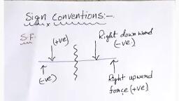
208, , Strength of Materials, , 44 SHEARING, , FORCE, , S.F.) AND, , 4BENDING MOMENT (B.MJ, When a beam, which is in equilih, under a series of forces, is cut in some, sectio, and the beam to the left to the section, , dbrium, ct, ion k, remain, , equilibrium (Fig. 4.6), then some force m, , ust a, the section. Prior to cutting, this, force WOuld, be provided by the adjacent material,, and W, act tangentially to the section. Hence, there, be a shearing force at the section., Numenica, this shearing force will be given by the, algeb, sum of the forces to the left or to the, right of, section. As a convention, an upwad force to, t, left of a section is counted as, producing negatio, shearing force. Similarly an upward force tot, right of the section will produce positive, at, , woud, , K 4, , sheanie, , force, , Non-magnetic multipurpose, , crane for, , minehunters., , Considering further the equilibrium ofte, material to the left of the section X (Fig., 4.6, follows that there can be no resultant, momenth, the left of the section. Hence,, any moment po, duced by the forces acting on the beam must k, balanced by an equal and opposite moment, pm, duced by the internal forces, acting in the beam, at the section. This is the, bending moment at te, section., , W, , W, , )Hogging, , R, , R, Sagging, , R, Fig. 4.6, , Fig. 4.7, , The, , bending moment is the algebraic sum of, moments to the left or right of the section. In, case, by considering, equiibrium, either for forces or, moments, the, forces to one side of the section is, balanced by the bending moment resultant, caused by the ap, and shearing force, section. The "sign coventions" for, actinga, moments is that a beam in, bending, "hogging" condition 15, ject to negative bending moment, and one in a, "sagging" condition to positive bending moment, 4.7)., , 45. SIGN CONVENTIONS, For writing the general expressions for, bending moment, and shearing force, the following sign conventions:, , Shearing Force. A shearing force having an upward direction, section or downwards to the left of the section will be taken "positive'., , to, , we, , shall be adop, , the right hand side, , Similarly, a 'negative' shea
Page 4 :
Chapter: 4 Bending Moments and Shearing Forces, force will be one that has a dowmwand direction, right of the section or upwand direction to the lefi, , Section., , 209, W, , the, of the, , to, , Bending Moment. A bending moment, causing, cocaviry uwands Will be taken as "positive' and called, , -X-A, , sagging bendng moment, a bending moment causing, comeiny upwands will be taken as 'negative' and called, , as, , (a) Beam, , hogging bending moment., , 4.6. CANTILEVER WITH AN END LOAD, Refer, , Fig. 4.8. A cantilever is supported at one, end only, being built-in at its, support, giving it a fixed, to, , (b) S.F. diagram, , slope at that point., , Consider, , a, , section XX, , at a, , distance x from the free, , end A., , W, S.F. at, , X = S, = - W, , B.M. at, , X= M, = - Wx, , (c) B.M. diagram, , Thus we find that S.F. is constant at all sections of, the member between A and B. But B.M. at, any section is, proportional to the distance of the section from the free end., At, , Fig. 4.8, , w/unit run, , x = 0,, , X, , B.M. = 0D, , i.e at A,, , At, , B, , X=l,, B.M. = W, , i.e. at B,, , (a) Beamn, , S.F. and B.M. diagrams are shown in Fig. 4.8., 7, , 4.7., , CANTILEVER WITH UNIFORMLY, DISTRIBUTED LOAD, , Wl, Wr, , (b) S.F. diagram, , Let the load be distributed over the whole length, of the beam, the loading being w per unit run (Fig. 4.9)., Consider the section XX at a distance x from the w/2, free end A., S.F. at X = S , = -, , B.M., , at, , X=, , 2, , wr/2, , (c) B.M. diagram, , wx, , Fig. 4.9, , M, =- WX5, 2, , Thus we find that the variation of the shear-force is according to a linear law, while the variation of bending moment is according to parubolic law, X= 0, S, = 0 and M, = 0, At, At, , and,, , x =l, S,, M, , =-, , wl, 2, , wl
Page 5 :
210, , Strength of, , Materials, w/unit run, , 4.8. CANTILEVER WITH UNIFORMLY, DISTRIBUTED LOAD AND, , A, , B, , CONCENTRATED LOAD AT THE, FREE END, , x, (a) Beam, , Fig. 4.10 shows a cantilever AB of length, (fixed at B and free at A) carrying a uniformly distributed load of w per unit run over the whole length and, , w+wl, , a concentrated load W at the free end., , Wwx, , Consider any section XX at a distance x from, the free end A. The S.F. and B.M. at section X, are, , (6) S.F. diagram, , respectively given by, , S,-(W+wx), and M, = - | Wx+, We find that the S.F varies, law while B.M. varies, following a, , W+w /2|, , Wxtwx 2, , following a linear, , (c) B.M. diagram, Fig. 4.10, , parabolic law., , 4.9. CANTILEVER CARRYING UNIFORMLY DISTRIBUTED LOAD, PART OF ITS LENGTH FROM THE FREE END, Fig. 4.11 shows a cantilever AB of, length I carrying a uniformly distributed, load of w per unit run for a distnace a from, the free end., , w/unit run, , B, , Consider any section between Cand, , A distant, , from the free end A., S.F. and B.M. at this section, , Ch-, , x, , are, , by, , given, , (a) Beam, , S=-WX, wa, , Wa, , and, M,=-Wr, 2, , The above relations hold, good for all, values of x between x =0 and x =a, (i.e. be, tween Cand A). Thus, for this range S.F. varies following a linear law while the, B.M. wa (-a/2), varies following a parabolic law., At x = 0, , and,, , (b) S.F. diagram, , Wa 2, , S, = 0, , (c) B.M. diagram, , M, = 0, , At x= a S, =- wwa, , Fig. 4.11, , and, M, =- wa, 2, , Now, , consider any section between, , The S.F. and B.M., , at, , the section, , S=-Wx, and, M,= -wa, , (), , B and C at a, , are, , given by, , distance, , x, , from the end A., , a, , FOR A
Page 6 :
2 4 2-l-2), Chapter, , :4:, , Bending Moments and Shearing Forces, , Thus between B and C, S.F. is constant, hut B.M. varies according to linear law., , at, , -, , RN, , wa, , 211, , 2 kN/m, , kN, , At x= a,, , B, Im, , M, = - wa (a> al2)=- w a, , D, , E, , lm, , -, , 2, Atx = l,, , m1m, , A, , m, , (a) Beam, , M, =- wa (l - al2), , Example 4.1., , Draw the S.F. and B.M., diagrams, for cantilever loaded as shown in Fig. 4.12 (a)., , ikN, , ikN, , Solution. S.F. calculations:, S.F. between A and C, i.e, , S.F., , SALC, at D ie., , S.F. will, to 5, , kN, , S,=-1-2x2, , 6kN, , =, , 6kN, , =-5 kN, , change uniformly from 1, , S.F. at E ie., S=-5-1, S.F. between E and B, Le., , 5kN, , 1 kN, , (b) S.F. diagram, , kN, , -6 kN, , IkNm, 3 kNm, , E-B-6 kN, , S.F. diagram is shown in Fig. 4.12 (b), 7 kNm, , B.M. calculations:, B.M. at A, , i.e., , M, , B.M. at C, , i.e., , M=-, , B.M. at D, , 1.e., , M=- 1 x (1 +2)-2x2, , = 0, , I xl, , =-, , 12 kNm, , I kNm, , x 2/2 =-3-4, , 18 kNm, , (c) B.M. diagram, , =-7 kNm, , Fig. 4.12, The B.M. diagram is a parabolic curve for the, portion CD on which there is U.D.L. Since it is not possible to draw a smooth curve with only two, points, so it is necessary to find out the bending moment at least at one more point between C and D., Let us consider point F in the middle of C and D., , Thames Bridge, London. Shear, bending and compressive stresses are important considerations while, , building bridges.
Page 7 :
212, , Strength of Materials, B.M. at F, , ie., , M=-1x(1+1)-2x1x=-2-1=-3 kNm, , B.M. at E, , i.e., , M-1x4-2x2, , B.M. at B, , i.e., , -4-8=- 12 kNm, , Mg-1x5-2x2+1+1 |-1x1= -5- 12-1l =-18tN, , B.M. diagram is shown in Fig, 4.12 (c)., , Example 4.2. Draw the S.F. and B.M. diagrams fora cantilever loaded as shown in Fig., Solution. S.F. calculations:, , S-2 kN, , 3kN, 2 kN/m, , 1 kN, , 4.13 (a, , 2kN, , 2kN, , S-2-2=-4 kN, From Cto DS.F. will change, uniformly from, -4kN to-6 kN and total value of S.F. at D i.e. S,, -6-3 -9 kN. From D to ES.F. will, =, , =, , B, , F, , E, , Im ImIm>Flm, m>Im>, , change, , uniformly from - 9 kN to - 11 kN., , D, , lm>, , (a) Beam, , S-11-1 =- 12 kN, S.F., , 2kN, , S-12kN, , 4kN, , diagram is shown in Fig. 4.13 (b), , 6kN, 9kN, , B.M. calculations:, , MA 0 , Mc = -2x1 = - 2 kNm, , Mp =-2 (1+1), =, , 4 2, , -, , -2x1-2x1x, , -1, , =, , (b) S.F. diagram, , 7 kNm, , -, , ME =- 2(1+1+ 1), , 1IkN, , 12kN, , 12kN, , -2, , x, , (1+ 1), , 2 kNm, , 2, , -3x1-2x2X,, , =-, , 7 kNm, , 6-4-3- 4 =-17 kNm, , M =-2 (1+1+1+ 1) -2, , 17 kNm, , x (1+1+ 1) - 3 (1+ 1) - 2x2, 28 kNm, , - 8-6 -6-8 =- 28 kNm, 40 kNm, M=-2(1+1+1+1+1), -2 (1+1+1+ 1)-3 (1+1+1), , =, , B.M., , (c) B.M. diagram, , Fig. 4.13, , -2x1-1x, 8-9-12-1, -10-, , diagram, , =, , is shown in, , 4.10. CANTILEVER, , Fig., , -40 kNmn, , 4.13 (c), , CARRYING LOAD WHOSE, INTENSITY VARIES, THE FREE, , FORMLY FROM ZERO AT, , THE FIXED END, Fig, 4.14 shows, from zero at the free, , a, , end, , cantilever, to, , w, , END TO, , w, , Aß of lengthl, carrying a load whose, unit, run at the fixed end. Let, per, the, , distance x from the free end A be w, per unit run., , UN, , PER UNIT RUN, , A, , intensity varies uniformly, intensity of loading at XX, at a
Page 8 :
213, , Chapter: 4 : Bending Moments and Shearing Forces, W, , W / u n i t run, , w , 7 X Since the intensity of load in-, , x/unit run, , ereases uniformly form zero at the free end to w at the, , fixed., Load acting for an elemental distance dxfrom, W,dx, thus the total load acting for any distance, , betweenx = a and, , x, , X-x-, , B, , =b, (a) Beam, x=b, , w, dx, , wx/2/, , wlI2, , X=a, , Parabolic curve, , Area of load diagram between, , (b) S.F. diagram, , and x =b., , =a, , Hence we arrive at an important conclusion that, the total distributed load acting on any segment equals, the area of the load diagram on that segment., S.F. and B.M. at distance x from the end A are, , given by,, , S, , =, , Area of the load, , diagram, , be-, , wx /61, , w/6, Cubic curve, , tween X and A, , (c) B.M. diagram, , -, , -i.*, , Fig. 4.14, , 2, F-, , WX, , 2, , and,, , M,, , =, , =, , Moment of the load, , and,, , At x=l,, , about X, , Area of load diagram between X and A x, distance of centroid of this diagram from X, , 6, , 21, , Atx= 0,, , acting on XA, , S=0, , M, =0, wl, , S,, , 2, wl, , and,, , M,-6, 6, , while the B.M. changes following, following a parabolic law, the cantilever loaded, Draw the B.M. and S.F. diagrams for, , a, , The S.F. changes, , Example, , 4.3., , Fig. 4.15 (a)., , section at a distance, btained by similarit of As ABC and ADE, , Solution. Consider, , a, , DE_BC, AD, , or,, , DE =, , or, , AB, , DE, , 2, , KN/m, , S.F. at the section,, l.e., , S=- Triangular, , load ADE, , x, , from A. Rate, , or, , 0ading DE, , at, , cubic law., as, , shown in, , the section is
Page 9 :
214, , Strength of Materials, 2 kN/m, , = - x AD x DE, , S.F. at the end B (where x = 4 m),, , 4, , =-4, , Spis, , a, , TIIn, , B, , D-x, , 4m, , kN, , (a) Beam, , The general equation for shear force at any section, second degree equation, the S.FE. diagram is a, , parabolic curve (Fig. 4.15), B.M. at the section DE,, , M,, , i.e., , =-, , Triangular, , load ADE, , x, , AD/3, , (b) S.F. diagram, , 4 kN, , B.M. atB (where x = 4m) i.e., M, , 12, , - 5.33 kNm, , The general equation for B.M. at any section is a, , third degree equation. B.M., bolic (Fig. 4.15 (c)., , diagram, , is a, , cubic para-, , ()B.M. diagram, 5.33 kNm, Fig. 4.15, , 4.11. CANTILEVER CARRYING LOAD WHOSE INTENSITY VARIES UN, FORMLY FROM ZERO AT THE FIXED POINT END TO, RUN AT THE FREE END, , Fig., , 4.16 shows, , w, , PER UN, , cantilever AB of length / (fixed at B and free at A), carrying a load wh, intensity, uniformly from zero at the fived end to w per unit run at the free end. It is convenie, to find S.F. and B.M.at, any section by considering the left part of the section. Consider any, seco, a, , varies, , XX at the distancer from the fixed end B., , Mechanisms are very sensitive to bending stresses.
Page 10 :
Ghapter: 4: Bending Moments and Shearing Forces, , 213, , Tet M be the reacting moment or fixing moment at B., S.F. at, , X = Algebraic sum of forces on BX, , w, wx, S 2+2T-2+, 21, WX, , B.M. at, , X = Algebraic sum of moment of forces and reactions on BX about X., , M,, , wl, , where, MR = moment of total load about B|, , wx, , X, , 21 3M, , wl, , = " - wx - W, w/unit run, , M, , A, , x, R, , (a) Beamn, , wl/2, , wl2, , Parabolic curve, (b) S.F. diagram, , wlr, wxw, 2, 6, , wi/3, , Cubic curve, (c) B.M. diagram, Fig. 4.16, , At x=0, , wl, , i.e. at B, Sp =, , 2, , At, , x =l i.e. at, , and,, , A,, , MA, MA, , Sa, , =-, , w, , 1, , and M =-, , 3, , wlwl_o, , t2, -, , w, , - 61, , wlw, , 3, , 2, , Example 4.4. Draw the shearforce and bending, Shown in Fig. 4.17, (a)., , wl, 6, , moment, , wl, , = 0, , diagrams for, , a, , cantilever loaded as, , Solution. It is convenient to find the S.F and 5.M. at any section by considering the left part of, , the section.
Page 11 :
216, , Strength of Materials, Let M be the reacting or fixing moment at B, , M, , = Moment oftotal load about B =|xlx, , Consider any section XX distant x from the fixed end B., -, , 6 kN/m, Wl, , of,, , s, =2, , Or,, , s,, S, , or,, , wx, 21, , 6x 4, , 6xx, , 2, , 2x4, , = - 12 +, , x, , 3x, 4, , RBwl/3, , S.F at B (when x = 0),, , -1= 4mn(a)Beam, , S - 12 +0= - 12 kN, S.F. at, , mid-point (when, mid-point, , S.F. at A, , (when, , x, , =, , x, , 2m, , 2m), , =, , - 12 +, , 7T, , 3 x 22, -, , =, , 4, , 9kN, , 9 kN, , 4m), , 12 kN, , (b) S.F. diagram, , SA - 1 2 + 3x42, =, , S.F., , diagram, , B.M., , M,, , at, =, , the, , Rg, , is shown in, , 10, kNm, , Xx-|, wr, , (c) B.M. diagram, , 3, , wl, , 6, , 6x4Xx, , 6xr, , 2, , 6x 4, , at, , 4, B (when x, , at, , mid span, , 32 kNm, , 3, , 12xB.M., B.M., , Fig. 4.17 (b), , section,, , wxx, =, , B.M., , at A, , (when x, , Fig. 4.17, , 6x 4, 3, , 32, =, , 0), , (when x, , =, , M-32 kNm, 2m), , Mmid span, B.M., , 0, , 4, , =, , 4m), , =, , 12, , x, , 2, , MA =12 x 4., , diagram is shown in Fig., , 32, , -, , 43, -, , 4, , 32, , =, , 24 -2-32 =-10 kNm, 48, , -, , 16-32, , =, , 0, , 4.17 (c)., , CANTILEVERS WITH COUPLES, Example 4.5., , Find the reaction, , Draw also the S.F. and B.M., , at, , diagrams., , the fixed end of the cantilever loaded as shown in, , Fig.* 180
Page 12 :
Chapter, , :4, , 217, , Bending Moments and Shearing Forces, , Solution. Total vertical load on the can30 50 kN, tilever =20+, =, , Vertical reaction at B =50 kN (up-, , 20kN, , 30 kN, , 290 kNm, , 30 kNm, , 20 kNm, , B, , D, , wards), , 2 m, , Taking moments about B:, , - 2 m>-2 m > - 2 m, , Sum of moments, , (a) Beam, , = - 20 x 8-30 (couple at C) - 30x 4+, , 50 k, , 20 (couple at E), , = - 160 -30 120+ 20 = - 290 kNm, (i.e. clockwise), Hence at B the support will provide a, , 20 kN, , balancing or reactingg moment of 290 kNm, 50 k, , 50 k, , anticlockwise., Hence the reaction at B will consist of an, , (b) S.F. diagram, , upward reacting force 50 kN and an anticlockwise, reacting moment of 290 kNm., , S.F. calculations:, 40 kNm, , A-C-D-20 kN, , D-E-B- 20- 30, , 50 kN, , =-, , 70 kNm, , S.F. diagram is shown in Fig. 4.18 (h), B.M. calculations:, , 110 kNm, 190 kNm,, , M =0, B.M. just on the right hand side of C, = - 20 x 2 = - 40 kNm, , B.M. just on the left hand side of C, = - 40 3 0 = - 70 kNm, , M =- 20x 4- 30, , =, , -, , 110 kNm, , 210 kNmn, 290 kNm, , (c) B.M. diagram, , Fig. 4.18B, , A machine part is being processed on a lathe.
Page 13 :
218, , Strength of Materials, B.M. just on right hand side of E, , 20 x 6 3 0 - 30 x 2 =-210 kNm, B.M. just on the let hand side of E, -210+ 20=-, , 190 kNmn, 30, , M=-20 x 8-30, , x, , 4 +20, , 160- 30- 120 + 20, = -290 kNm = reacting moment at B, , B.M. diagram is shown in Fig. 4.18 ()., , 4.12. SIMPLY SUPPORTED BEAM CARRYING A CONCENTRATED LO, |AT MID SPAN, Fig. 4.19 shows a beam AB simply supported at the ends A and B. Let its span be I and carr, point or concentrated load W at the mid span. As the load is, placed on the span, re, tion at each support is W/2., W, , symmetrically, , RA =, , RB =, , For any section between B and, S.F. = + W/2, , C,, , C, , /2-, , For any section between C and A,, W, , S.F=", *, to-, , (a) Beamn, , 2, , W, , W =-, , At the section C the S.F., W, W, , /2-, , 2, , changes, , from, , 2, , B.M., , distance, , at a, , x, , from B in BC,, , WI2, , Wx, , B.M., , at B, , M, = 2, (wherex =0),, , (b) S.F. diagram, , M =0, B.M., , at C, , (where, , at, , Mc, 4, distancex from, , x, , l/2),, , =, , WI, , WI, , =, , B.M., , a, , M,, B.M., , at C, , "4 - W, , x, , =|/2,, , B.M. atA where x =l,, , Note., , B.M. at, , CA,, , Wx, , =, , where, , B in, , supports, , in, , (x, , Mc, MA=, , case, , (c) B.M. diagram, , -1/2), +, , Fig. 4.19, , WI, 4, , W, , W, , 2, , 2, , of simply supported, , 0, beams is, , always, , zero., , 4.13 SIMPLY SUPPORTED BEAM CARRYING A, CONCENTRATED10, 'NOT AT MID SPAN, Let the, , beam Aß of span / (ig. 4.20) carry a concentrated, , distance b from B., , load W au, , a, , dist:nee, , a, , fronA
Page 14 :
Ghapter :4: Bending Moments and Shearing Forces, Taking moments about A to determine the, support reactions, we have:, R, , B, , Xl = W xa, C, , Wa, , R, But,, , R, , T, , Wb, , RAT, , + Rg = W, , RA, , (a) Beamn, , R, , Wa, , T, , W(l -a) Wb, , =W- Wa, , S.F just to the left of B is +, , Wall, , Wa, Wb/l, , It remains constant upto C., , L, , S.Fjust to the left of Cis, , Wa, , (b) S.F. diagram, , Wh, , It remains constant upto A., , B.M. at the supports A and B =0, , Wab, , B.M.at C, Mc ="xb ="Wab, (c)B.M.diagram, , Thus B.M. is naxinum at C where, , Fig. 4.20, , S.F. changes sign., , 4.14. SIMPLY SUPPORTED BEAM CARRYING A UNIFORMLY DISTRIBUTED, LOAD OF w, Fig. 4-21, , shows, , a, , PER UNIT RUN OVER THE WHOLE SPAN, , simply supported, , beam AB, , carying a uniformly distributed load (U.D.L.) of, , W per unit over the whole span., w/unit run, , 00000000000B, , X-x, R, , wl/2, , (a) Beam, , Rgwl/2, , wl/2, , wl/2, , (b) S.F. diagram, , Parabolic, curve, , wT/8, , (c) B.M. diagram, Fig. 4.21
Page 15 :
220, , Strength of Materials, By symmetry each support reaction is equal, i.e.,, , RA R, , wl, , F, , S.F. at the section X at the distance x from B,, , S =+, , wl, , WX, , Sg+, , S.F. at B (where x =0), S.F. at mid span C, wherex, , = 0, , S.F. at A (where x = ),, , S =+, , B.M. at the section X., , M, =+, , B.M. at B (where x = 0)., , M, , B.M., , MA, , at A(where x, , For the B.M., , )., , =, , -, , = 0, =, , be maximum put, , to, , w, , dM, dx, , for eqn. (i), , 0, , equal, , to zero., , dM, dx, , i.e,, , X, , Ifor, , =, , the B.M. to be maximmum,, , it, , may be noted that, S.F. at, , this point is zero, , Max, 8, , 4.15., , GENERAL RELATION BETWEEN THE LOAD, THE, SHEARING FOR, AND THE BENDING MOMENT, , Refer to ig. 4:22. Consider a short, length ôr of a beam at a distance x from some origin. Lel, over this short, be, w, length, per unit length acting vertical downwards; then the, shearing 10, over this short, length will increase from Sto (S + öS) while the, moment, bending, increases, (M +dM). This short length is in, from M, equilibrium under both vertical forces and couples., load, , Vertical forces:, , S+, , (S+dS) - S= w dSr, , SS = w.&r, or,, , 1, , M, or, , dS, , wox, , Couples:, -, , (M +SM), , or,, , Since, , SM, , -, , =-Sor + wôr, =-, , is a small quantity of, order, it may be taken as zero., -, , SM, , =, , a/2, ox, , 2, , S+8S, , S.or +(&x), , (åx), , -S ôr, , or, , M+8M| M+8M, , W, , dr, , M, , M, , the second, S =, , M, , Fig. 4.22
Page 16 :
221, , Chapter: 4 : Bending Moments and Shearing Forces, , Unlike land automobile,, , Putting, , dx, these relations into, , form, , integral, , ...(iii), , M sdr, , (i), that the, , rate, , the, , rate, , equation (i) it is concluded, of change of S.F. at any section represents, of loading at the section., From equation (i) it is, , dM, dx, , or, , =, , 0. Thus, , or, , 2 kN +, , mini-, , 2 kN, , at the sec-, , changes sign (because, , 4 kN, 4 kN, , (b) S.F. diagram, 6 kNm, 4, , 4 kNm, , kNm, , T, , (a)., , Solution. To determine the support, taking moments about A, we get, , 4 2x 1 +4 (1 + 1) +2(1, , reactions, , +1+, , (c) B.M. diagram, , 1), , Fig. 4.23, , = 2+8+6 =16, , Rg, But,, , E, -Im, -Im>-Im, R 4 kN, (a) Beam, D, , 2 kN, , and B.M. dia-, , X, , 2 kN, , 4 kN, , Example 4.6. Draw the S.F., shown, beam loaded as, ams for simply supported, 4.23, , RA, , be fatal., , B, , C, , mum or minimum., , Fig., , 4 kN, , 2 kN, , -Im, R 4 kN, , then it passes through zero) the B.M. is eithermax, , in, , can, , have., , at any section represenis, , 0 i.e., S, , tions where S.F. is zero, , shaft, , concluded that the, , the S.F. at that section., maximum, The B.M. at M shal be, , mum when, , we, , S= wds, , of change of B.M., , or, , ...(i), , From, , rate, , popeller blades, , dM, , L, , and in the, , in the air. Failure of, , helicopter flies, , +, , Rg, R, , 4 kN, 2, , =2+4 +, =, , 8-, , Rg, , =, , =, , 8, , 8 kN, , -4, , =, , 4 kN
Page 17 :
222, , Strength of Materials, S.F. calculations:, , SB-E +4 kN, E-D 4-2 2 kN, Sp-c 2-4=- 2 kN, , S.F. diagram, , Sc-A, is shown in, , B.M. calculations:, , 2-2= - 4 kN, , Fig. 4.23 (b), Mg = 0, , ME =4xl =4 kNm, Mp, , =4(1+1) - 2xl =8 - 2 =6kNm, , Mc =4 (1+1+1)-21+1) -4x1, 12 4 4, 4 kNm, MA =4 (1+1+1+1) -2(1+1+1) -4 (1 + 1) - 2x1, 16 6 - 8 2 0, =, , -, , =, , B.M., 4.24, , diagram, , is shown in, , -, , -, , Fig. 4.23 (c)., , Example 4.7. Draw the shear force and bending diagrams for the beam shown, loaded in Fig, (a). Clearly mark the position of the maximum, bending moment and, determine its value., , 2kN/m, , ikN, A, , 4kN, , 000000000, B, F, 2mIm}<lm>, , Ima.D, , R 3.5 kN, , Rg 5.5 kN, , (a) Beamn, , 5.5 kN, , 1.5 kN, e, , 12.5kN b, , 0.75m, , -2.75 mn-, , 3.5kN, , (b) S.F. diagram, , 6kNm, , 7.56kNmn, , 7kNm, , 3.3kNm, T, , 5.5kNm, , (c) B.M. diagram, Fig. 4.24, , Solution. Let R,, A, we have:, , Ra X6, , and, , R, be the respective support reactions at A and B., , 1x1+2x2+1+1 |+ 4x5 =1+ 12 +20, , Taking moments abo, 33
Page 18 :
Chapter :4, , 223, , Bending Moments and Shearing Forces, , Rg, 5.5 kN, RA+R =1+2x2+4 9, , But,, , R 9 - R , =9 - 5.5, 3.5 kN, S.F. calculations:, , Sg-, , 5.5 kN, , Sp-E 5.5 -4 = 1.5 kN, From E to D S.F. changes from +1.5, , to 2.5 kN, , kN, , D-C-2.5 kN, , ScA-2.5 - 1, 430, , = - 3.5 kN, , S.F. diagram is shown in Fig. 4.24 (b), To locate the point between D and E, where S.F is zero we have from the two similar As abc and cde:, , ab, , 2.5, , 1.5, , ac, , 2-cd, , cd, , Industrial gas turbine., , 2.5 cd = 1.5 (2- cd), 2.5 cd 3 -1.5 cd, , or,, , cd = 0.75 m, , B.M. calculations:, , M =0, , M= 5.5, , M =5.5, B.M., , at, , the, , x1, x, , =, , 5.5 kNm, , 2-4x 1, , point, , where S.F is, , Mmax, , =5.5 x 2.75, , zero, , 7 kNm, , =, , is the maximum and is, , 0.75, , -, , 4x (2.75, , - 1)- 2x 0.75 x.19, 2, , = 15.125- 7.0- 0.5625 = 7.56 kNm, , Mp, , =, , 5.5 x4- 4x3-2x2x, , =, , 5.5, , Mc, , x, , 22- 12, , 5-4x4-2x2+1, , -, , 27.5, , 4 =6, , kNm, , -16 -8, , 3.5 kNm, , MA = 0, , B.M., B.M., , diagram, diagram, , Example, , portion DE which carries, shown in Fig. 4.24 (c), , for the, is, , R, , X, , 2, , and, , 1x0.5 x0.5/2, , = 0.125 +, R, , R, , a, , parabolic, , diagramsfor the beam shown in Fig., we, Rp, taking moments above A, get, , 4.8. Draw the B.M.and S.F., , Solution. To find reactions, , of,, , U.D.L. shall be, , 2x0.5 + 5x1.5, , +, , 1+7.5, , 5.06 say 5.1 kNN, , +, , 1.5, , =10.125, , +1x1x|, , curve., , 4.25, , (a)
Page 19 :
224, , Strengthof Materialss, 5 kN, , 2 kN, , But,, , R+R=1, , x0.5, , +2 +5 +, , = 0.5+2+5 + 1, , A 000, , 8.5 kN, , =, , 0.5m, , S.F calculations:, 5.1-1x 0.5 -5, , Sp-c-0.4-, , 0.5m>+0.5m>0.5m>, Rg 5.1k, (a) Beam, , RA3.4 kN, , Sg5.1 kNN, 1, , x, , 0.5, , 4.6 kN, , -0.4 kN, , =, , =, , B, , E, , D, , C, , R = 3.4 kN, S, , 1 kN/m, , I kN/m, , 1x 1, , . 1 ky, , 0.9 kN, , -, , S - 0 . 9 - 2 = - 2.9 kN, S = - 2 . 9 - 1 x 0.5 = -, , 3.4 kN, , S.F.diagram is shown in Fig. 4.25 (b)., , 0.9kN, , B.M. calculations:, , M=0, M, , 3.4 kN, , = 5.1 x 0.5 - 1 x 0.5 x 0.5/2, , kN, , 2.9 kN, (b) S.F. diagram, , 2.425 kNm, M, , 0.4, , 1.65 kNm2.I, , kNm, , 2.425 kNm, , = 5.lx1-5x 0.5 - 1x1x, =, , Mc, , 5.1, , -, , 2.5, , -, , 0.5, , TT, , 2.1 kNm, , =, , =5.1x1.5 - 5 x 1 - 1x1 (0.5 + 0.5), , = 7.65 -5, , (c) B.M. diagram, , 1 = 1.65 kNm, , Maximum S.F. is 5.1 kN at B and the, , Fig. 4.25, , maximum B.M. is 2.425 kNm at E., B.M., , 4.16., , diagram is shown, , in, , Figure 4.25 (c)., , SIMPLY SUPPORTED BEAM CARRYING A LOAD, WHOSE INTENSITY, VARIES UNIFORMLY FROM ZERO AT EACH END TO, UNI, w, , RUN AT THE MID SPAN, , For 4.26 shows, , a, , simply supported beam AB of span l carrying, , Total load on beam, , =, , the load, , PER, , mentioned above., , WX, , 2, , Rate of, , loading at a, , RA R= 4, , section, EF, , at, , distance, CD, a, , BE, , BC, , EF, , CDx BE, , =, , S,, S.F. at B(where x = 0), Sp =+ w, , from B, , (By similarity of As BCD and BE, BC, , S.F. at the section is, , x, , wX*_2wx, , x xx, , S.F. at C (where x = /2), , Se+, , 70/2P =o, , -
Page 20 :
Zz5, , Chapter : 4 : Bending Moments, , and Shearing, , Forces, , D, , 2wx/l, , S.F. at A., , S+, , wx =., , B, , wl, , 4, equation from S.F. is, , E-I, , A, , The general, aa, equation representing, second degree, parabolic., the S.:. diagram is, parabola, so, section under considerB.M. at the, , RB w l 4, , - !1/2-, , a, , RAwl/4, (a) Beamm, , wl4, , ation is, , M,, , 4, x, , xl3 =, , wia, , wx, , wl, , (b) S.F. diagram, , X3I, , both the supports A, B.M. is zero at, the beam is simply supported., , and B since, be maximum, For the B.M. to, , we, , wl/2, , have, , w, , dM, dx, , Wx, , =, , 0, , 4, , (c) B.M. diagram, , l/2 (here the S.F. is zero), i.e.,, is,, thus at the mid span and, The maximum B.M. is, =, , x, , wl, M, , 4.17., , 8, , max, , Fig. 4.26, , wl, , wl, , 12, , 24, , WHOSE INTENSITY, CARRYING A LOAD, BEAM, PER UNIT, SIMPLY SUPPORTED, w, AT ONE END TO, ZERO, FROM, VARIES UNIFORMLY, END, AT THE OTHER, , RUN, , Fig., , 4.27 shows, , a, , simply supported, , load whose inbeam AB of span I carrying, from zero at the right, tensity varies uniformly, the left end A., end B to w per unit run at, vertical reactions, Let R, and R, be the, of the beam, at A and B. For the equilibrium, , wxll, , a, , taking moments, , about, , A,, , Rgwl/6, R, , Wl/3, , (a) Beamm, , have:, , we, , B, , D, , A, , wl/6, Wl, , a6, But,, , RA + Rp =, , wl/3, , (b) S.F. diagram, , wl, wl, , R, Rate of loading, tance of x from B:, , (from, , 6, at a, , section at, , a, , dis-, , r, , w, , 9/3, , DE, , AC, , DB, , ABB, , similar As BAC and, , (c) B.M. diagram, , BDE), , Fig. 4.27
Page 21 :
226, , Strength of Materials, , S.F. at A (where x = ),, , B.M. at the section is, B.M. is naximum when, , Thus,, , -xxx=, , wx, , 2, , 6, , S+6, wl W, , SA62 x(0 =- = -, , Wl, , 6, , DE = ", , Wl, , S.F. at B (where x = 0),, , S.F. is zero when, , WX, , S, = Ra-load, , S.F. at the section,, , Or,, , AC x DB, AB, , DE, , or,, , = 0 or X=, , 2, , M,, dM, dx, , -, , 6, x, , wx, , xx - x x, wx, 2, , 0, , (here S.F.is zero), , =, , 3, M max, Mmax6, , 61, , w, , w, , 63, , w, , 183, , wl, , 93, , B.M. at both the supports A and B is zero since the beam is simply supported., , GLBELD, , A horizontal, , boring, , machine.
Page 22 :
227, , Chapter :4: Bending Momets and Shearing Forces, , wkN/m run, , Example 4.9. Calculate the values of, numand ainimum bending moments and, , X, 15kN, , simply supported beam, , hearingforcesfor th, , in Fig. 4.28 (a).Draw the, ting moment and shearing force diagrams, , OkN, , loadeda s shown, , nding, indicatingthe, , 1oscale, , Cxx, , significant value: along, RA, , Solution. To find reactions R and R, moments above A, we get, , Rg x6=30, , t15x5, , Im, , Im, , 17.5 kN, , B, , I, , 3 m-, , Im, , the beam., , taking, , D, , R27.5kN, 27.5kN, , (a) Beam, , 12.5kN, , -2.29m, , T, , = 90+ 75 = 165, , (b) S.F. diagram, , 165, , R,, kN, RB ==27.5, 6, But,R, , +, , Rg, , 30, , =, , +, , RA =45, , 15, , 17.5kN, 44.23 kNm, , 45, , 40 kNm, , 27.5 =17.5 kN, , 27.5 kNm, , 17.5kNmM, , If the rate of loading at D is w, then, , x3x w = 30, 30x 2, W=, , (b) B.M. diagram, , = 20kN/m, , Fig. 4.28, , S.F. calculations:, Starting from left side:, , SA, , 17.5 kN, , S= - 17.5 +X x x (rate of loading, 20x, , at, , XX), , S =-17.5+XIx, , i.e.,, , S-17.5+ 10, , Or,, , .), , 3, , S, , When,, i.e.,, , =-, , -17.5 +, , 10 x, 10, , or,, , p-E (putting x, Eqn. (i) giving S.F, , =0, =0, 52.5, , or, , =3 m) = - 17.5+, , for CD is second, , SE-, , x=, , 2.29, , m, , 10x3 12.5 kN, , degree equation representing a parabola.), , 12.5 + 15, , =, , 27.5 kN, , S.F. diagram is shown in Figure 4.28 (b), , B.M. calculations:, MA = 0, , Mc =17.5x1, , M,, , =, , 17.5 kNm, , =175 -xxx, (1+, , =, , 17.5 (1, , +, , x)-, , 10x, 9
Page 23 :
228, -, , Strength, , Mmax when x, , =, , of Materials, , 2.29, , m,, , where S.F. is zero), 10x (2.29), 9, , = 17.5 x (1 + 2.29) -, , 57.57- 13.34 =44.23 kNm, , Mp, ME, , =17.5, , (1+3)- 10x3*, , =, , 9, 27.5 x 1 = 27.5 kNm, , 70, , 30, , =40 kNm, , MB = 0, , B.M., , diagram is shown in Figure 4.28 (c)., Example 4.10. The intensity of loading on, , simply, , suported, of 4 m span incre, gradually from 30 kN/m run at one end to 130 kN/m run at the other., Draw the S.F. and, a, , beam, , B.M. diaen, , Solution. Refer Fig. 4.29 (a). The load, may be divided into:, X, E, , 130kN/m, 30 kN/mn, , A4, , rBA, , 4m, , R, , 193.33 kN, , R, , (a) Beam, , 126.67 kN, , 126.67 kN, 2.2 m, , (b) S.F. diagram, , 193.33 kNN, , (c) B.M. diagram, Fig. 4.29, , ()A uniformly distributed load (U.DL.), of 30 kN/m run throughout the span., (ii) A uniformly increasing triangular load which, is zero at the, right end B and im, unifornly to 100 kN/m run at the left end A., To find reactions R and, R, taking moments about A, we get, , Rx 4, , 30x, , 4x, , +5x 4x 100 x=, , 240+ 266.67, , Rg = 126.67 kN, , But,, , R+Rg 30 x 4 + x4x100, =, , RA, , =, , 120, , 320-126.67 =193.33 A, , +, , 200, , 320 kN
Page 24 :
Moments and Shearing, , Chapter: 4: Bending, S.F. calculations:, , the, , Consider any, (FG +, line FH=, , section, , XX at, , distance, , a, , 229, , Forces, , at the section is indicated by, from B. Rate of loading, , x, , GH)., , similar As CDE and, From the two, , GH, , DE, , GC, , DC, , CGH,, , DEx GC, Of,, , have, , we, , 100xX25 x, 4, , DC, , Rate of loading atx, S.F. at the section,, , =, , 30, , 25, , +, , x, , BCGF +load CGH), , Sy =126.67 (load, , =126.67- (30x +xxx25 x), = 126.67 - 30x - 12.5 x, TABLE 4.1, Xmetre, , 126.67, , S, kN), , M, (kNm), , 108.54, , 84.17, , 53.54, , 59.06, , 107.51, , 142.19, , -, , - 26.45, , 16.6, , 132.5, , 157.82, , 160, , 75.83, , 4.0, , 3.5, , 3.0, , 2.012e 2.5, , 1.5, , 1, , 0.5, , -, , 131.45, , -, , 193.33, , 80.95, , B.M. calculations:, , M,, , B.M. at the section,, , 126.67x, , =, , 126.67x, , 30, , -, , x x12.5 x x, , 15 2, , -, , 30x 12.5 r= 00, 2+2.4 r- 10.13 =0, , 126.67, , Mmax, , =126.67 x, , 278.67, , =, , m, , intervals, , S., , plot the S.F., , and BM. diagrams, , Example, , 4.11., , Fig., , 2.2, , are, , 4.30, , shown in, shows, , (a), , a, , 15 x, , -, , 72.6, , -, , and B.M. diagrams, , (Table 4.1)., , +4 x 10.13 2 . 2 m (neglecting - ve value), , 2, , X, , 0.5, , lL.3, , -, , -, , -2.4 + (2.4), , In order to, , 3, , S=0, , For maximum B.M., , i.e.,, , =, , -, , 2.22, , 44.37, , =, , X, , -, , 2.23, , 161.7 kNm, , tabulated at, been calculated and, their values have, , and (c) respectively., Fig. 4.29 (b), beam AB, , 4, of length, , acted upon, , m, , by, , the forces and, , moments. Draw the B.M. and S.E diagramsS., we get, moments about A,, taking, and, R,, reactions, R,, 22.5 + 30+ 60, Solution. To determine, 1.5/2+30+20 x 3, x, 1.5, x, 20, =, , Rx4, , R, But,, , R+R, , R, , =, , 28.12 kN, , =, , 20, , x, , 1.5, , +, , 20 50 kN, , 50-28.12, =, , =, , 21.88 kN
 Learn better on this topic