Notes of MOS 3rd Sem Mining GEC, MOS moment area method.pdf - Study Material
Page 1 :
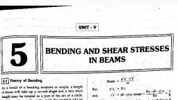
15.41, , X10 mm, 200 x 10°x 13.5 x 10⁻⁶, Hence. maximum deflection 5.7 mm, (downward) (Ans.), , =, , - 5.7 mm, , =, , 8.8., , MOMENT AREA METHOD, , The moment area method is, partially convenient is case of beams acted upon with poir, loads in which case bending moment area consists, of triangles and reactangles. In the case ot, distributed load the determination of the position of centroid itself involves, integration and as such, it no longer remains, simpler than Macaulay's method. However, this method may be conveniently, used in certain standard cases of distributed load where the, position of the centroid of the bending, moment area is known., beam AB Fig. 8.40 (a) carrying such load that it has bending diagram, Consider, Fig. 8.40 (b). Let the beam bend into AC'D'B as shown in Fig. 8.40 (c), a, , Fig., , a, , an element of small length CD of the beam at, Now, consider, 8.40 (a, b)., , a, , distanee x trom, , B, , as, , as, , shown, , in, , shown, , in
Page 2 :
Chapter: 8 : Deflection ofBeams, , C, , D, , 445, , B, , (a), , B.M.D, , G, , M, , (b), , B, , R, D, , Q, (c), , Reference line, , Fig. 8.40, , Let,, , Bending moment between, ox = Length of the CD, , M, , Radius, , R, , 80, =, , A, , =, , =, , C and D,, , of the bent up beam,, , at C" and D', facing the reference line or it, Angle included between the tangents, the elementary portion dx,, is the change of slope over, also angle between the two normals,, over entire span,, Area of bending moment diagram (B.M.D.), G of the entire B.M.D area from the, Horizontal distance of centre of gravity, , reference line, and, =, , between the tangents drawn, The angle in radians, included, the reference line., the beam, i.e. at A and B and facing, , at the extremities of
Page 3 :
446, , Strength of Materials, From the geometry of the bent up beam, we lind that C, år = R .80 (substituting C'D' = ör*), , or, , We knowv that for, , R, a, , loaded beam,, M, , E, R, EI, , R, , Or, , Putting, , = R 80, , this value of R in, , M, , equation (i),, , The total, , change of slope, between the limits zero andl., , EI, from A, , =, , 0, , may be found out, , by integrating, , the, , above equation, , =EI M8x, , El, M ox, , get, , EI, to B, , =, , But, , we, , Area of the B.M.D., , over, , the entire span., , EI, , .8.26), , Now draw tangents at C and, D. Let these two, tangents meet at P and Q on the verücal, (reference) line through B as shown in Fig. 8.40, From, (c)., the geometry of the, tangents at C andD'also meet at angle d9,, figure, we find that the, PQ = x.86 = AMoX_M, , and,, The total, , intercept may be found out by integrating theEIabove, , y= Mox x1, But, , ôx x, , EI, , 0, , M ox, , x, , This kit is used in hoists for, , =, , EI, , Moment of area of, , lifting weights, using, , equation between the limits zero anu, , M ox x, , B.M.D. over portion &r, about the reference, , metal ropes. The kit is, called 'hoist rescue, , kit, , .
Page 4 :
Chapter: 8: Deflection of Beams, M, , dr, , x, , =, , 0, , Moment, , of area of B.M.D., y==4AX, , The product El is known as flexural rigidity, and (8.27) are known as Mohr's theorems., area, , the entire span ör, about the, , reference line, AT, , Note. The, , over, , of the bending moment, , ..(8.27), , EI, , of the beam. The results given in equations (8.26), , diagram (B.M.D.) above the, , line will be taken, , zero, , and vice versa., , Expressions for A (area of B.M. diagram) and, 1. Rectangle, , A, , bh, , b/2, b, , 2. Triangle, C, , A -, , h A=(1/2) bh, , h, , G, , b/3, , (1/2) bh, , TT-T, , G, , 1/3(b+¢)>, b, , b-, , 3. Curves, () y = k2, , A, , G, , TTTTH, , -, , = (2/3)bh, , A= (1/3)bh, , -(3/4) b, b-, , (iii) Sine curve, , (i) y = kr, , TT TTTT, G, , TT, , L, , 2, , b, , T, , G, , 3/8 b KE, -b-, , A n+h, , TA=(2/7)bh, G, , -(2/1)b-, , b-, , Fig. 8.41, , as, , positive, , (horizontal distance of c.g. of B.M., , diagram) for some familiar B.M. diagrams:, , h, , 447
Page 5 :
448, 8.8.1., , Strength of Materials, Determination of Maximum Slope and Deflection in Important Ca, Case I. Cantilever beam with a concentrated load at the free end:, Fig. 8.42 (a, b, c) shows a cantilever with a concentrated load W acting at free end, the ek, , ekasti,, , curve and B.M. diagram respectively., The slope and deflection will be maximum at the free end. We known that,, A, , max, , EI, , WI2, , A=)WI) ="2, , From Fig. 8.42 (c), , (a) Loaded cantilever, , max, max, , (b) Elastic curve, , (2/3), G, WI, (c) B.M. diagram, , Fig. 8.42, , W, .(8.20), , 2EI, Ax, , Also,, , max, , 3W3, , El, , 3, , 3 EI, , ET, , WI, Thus,, , mar, , ..8.29), , 3EI, , Case II. Cantilever beam with, , a, , concentrated load, , Refer to Fig. 8.43 (a, b, c), , at any, , point:, , The slope and deflection will be maximum at the free end as usual., , max, But,, , A, , E1, , a2, , A=;(a)(Wa) =Wa2, Wa, 2EI, , and,, , Ymax, , Ar Wa, El 2EI, =, , -at
Page 6 :
Chapter : 8: Deflection of Beams, max, , Or,, , Ya, , Also,, , Wa-, , 449, .(8.31), , AxWa(2, EI, , Wa, , ya 3EI, , ..(8.32), , W, , (a) Loaded cantilever, , mar, , (b) Elastic curve, , Ya, , --a)|, V, , G, -x =(-a +a, (c) B.M. diagram, Fig. 8.43, , The, e, above part of hoist, , rescue equipment holds and locks the metal rope as and when required. This, , is also used in heavy cranes and pile drivers.
Page 7 :
450, , Strength of Materials, Case 1ll. Cantilever beam with uniformly distributed load:, Refer to Fig. 8.44, w/unit run, , (a) Loaded cantilever, , max, Ymar, , (b) Elastic curve, T- (3/4) -, , Wi/2, , (c) B.M. diagram, Fig. 8.44, , The total load, , on, , the, , cantilever, , =, , wl, , =, , W, A, , Now,, , ElEI, , But, , A, , W, 6 El, , 8.33), , W, , 6El4, , Ax, , and,, mar, , Or,, , EI, , W, , mar, , 8 EI, , Case IV. Simply supported beanm with, concentrated load, Refer to Fig. 8.45. In this case as the load is, , mum, , at the mid span and, , But,, , slope, , shall be, , .8.34), , at the centre:, , symmetrically placed the deflection will be maxr, , maximum at the ends., , A, , area, , of shaded triangle [Fig., , 8.45 (c), , 16, , W, , 8mar, and,, , Ymax, , 16 EI, =, , EI, , (8.35)
Page 8 :
Chapter : 8 : Deflection of Beams, , 451, , 48 EI, Hence, , mar, , W, 48 EI, , ..(8.36), , W, I/2-, , /2, , (a) Loaded beam, , max, , max, , (b) Elastic curve, , Wl/4, , G, , (c) B.M. diagram, Fig. 8.45, , Case V. Simply supported beam with uniformly distributed load:, Refer to Fig. 8.46. In this case also the deflection will be maximum at the mid, span and, will be maximum at the ends., w/unit run, , (a) Loaded beam, , mar, , Aax, (b) Elastic curve, , WI/8, , G, T 5/8 (l/2), I/2(c) B.M. diagram, Fig. 8.46, , slope
Page 9 :
452, , Strength of Materlals, Now,, But., , A= Area, , of shaded part [Fig. 8.46 (c), , ), W2, 24, , (where, W= wl), , WI2, , ax, , 24 EI, , .3.35, , Ax, , and, , max, , EI, , W2, , 24E, 5WIS, , or,, , max, , ....3, , 384 EI, , WORKED EXAMPLES (Cantilevers), Example 8.24. A steel cantilever of span 2.5 m, , caries a point load of W kN at its, free end. T, of inertia of the section of the cantilever is 9900 cm'. the, at, lf, the, deflection, free end is na, exceed 0.75 cm, what must be the value, of W? Take E 210 GN/m?., , moment, to, , =, , Solution. Refer to Fig. 8.42, Given: Span of cantilever,, M.O.IL of the section,, Deflection of the free end,, , l2.5 m, I=9900 cm = 9900 x 10-3 m, , y,a=0.75 cm 0.75, Young's modulus of elasticity, E 210 GN/m2, =, , x, , 102, , m, , =, , Value of W:, , The deflection, , at, , the free end of, , by the relation:, , a, , cantilever, , Ymax, , 3x, , (Eqn.8., , W(2.5, 210x 10 x 9900 x 10*, , 0.75x I10*x 3x, 29.94, , Hence the value of point load, , load W (at its free end) 1s, , WI', 3 EL, , 0.75x 10², , O, , carrying a point, , x, , 10* N, , 210 x 10 x 9900 x 10, (2.5), or 29.94 kN, , W 29.94 kN (Ans.), , Example 8.25. A cantilever with a span of tm carries a point load, maximum slope is I.5 degrees, calculate the deflection at the free end., , at, , its, , free enl.
Page 10 :
Chapter, , 8: Deflectlon of Beams, , 453, , Solution. Refer to Fig. 8.42., , I=4m, , Gien: Span of the cantilever., , "ma.5, Maximum slope,, Defleetion at the free end yua, , We know that, in this case,, , WI2, Maxium slope,, , 2 El, ), , Ws, , Ymax, , and, maximum deflection,, , 3 EI, , The picture shows splined shaft, gears and bearing of, a machine part., , ..(ii), , WI, , But, , = 1.5°=1.5 x, , 10, , 180, , 2EI, , WI, =, , Or,, , = 0.02618radian (given), , 2x0.02618 = 0.05236, , EI, , Substituting this value of, , W2, , in equation (i), we get, , EI, max, , W, , =0.05236 x =0.06981m, , 3, EI, Hence, deflection at the free end =69.81 mm (Ans.), load 30 kN at a distance, Example 8.26. A cantilever beam with a span of 3m carries a point, at the free end and at the point where, of 2m from the fixed end. Determine the stope and deflection, , load is applied., Take:, , M.O.1., , ofthe section =11924 cm',, , and E, , 200 GN/m., , Solution. Refer to Fig. 8.47., , 30 kN, , - a =2 mm, , (a) Loaded cantilever, , max, , (b) Elastic curve, Fig. 8.47, , Given: Span of cantilever beam,, l, , 3m, , Distance of point load from the fixed end,, a = 2 m
Page 11 :
Strength of Materlals, , 454, , Magnitude of, , the, , point load,, W, , 30 kN, , I= 11924 cn = 11924 x 10-* m, , M.O..., , We know that in this case: Slope,, , Wa, , max, , 2 EI, , (30 x 1000) x, , 22, =, , 2x 200 x 10 x11924 x 10-, , 0.002516 radian. (Ans, , Deflection at the free end,, , (30x 1000) x 22, ymax, , 2x 200x 10x11924x 105 L, = 0.00587 m = 5.87 mm, , Deflection at a distance, i.e. where the load acts,, , (Ans.), , a = 2m, , ya=, , Wa, 3 EI, , (30x1000) x(2), 3x 200x 10x 11924 x 108, =, , 0.00335, , =3.35, , m, , (Ans.), , mm, , Example 8.27. A cantilever 150 mm wide and 200 mm deep projects 2m out of a wall, and is, carrying a point load of 40 kN at the free end. Determine the slope and deflection of the cantilever a, , the free end., , Take, , 2.1 x 10³ MN/n2, Solution. Given: Width of the section,, E, , Depth of the section,, , =, , b, , 150 mm =0.15 m, , d, , 200 mm = 0.2 m, , 0.15, , M.O.I,, , Length, Young's modulus,, , x, , 0.2 =, , 10, 12, 12, I= 2m; Load, W = 40 kN, , m, , E= 2.I x 10 MN/m2, , Slope at the free end, O, max, Using the relation,, , =, , WI, 2 E, , we get, , 40x 22, (2x 2.1 x 10°x 10')x 10-4, , Deflection, , at the free, , Using the relation:, , 0.003809 radian, , end, y,uus, , ymax, , WI, 3 EI, , we get, , 40 x 2, max, =, , 3x (2.1x, , 0.005079, , m, , 10x 10'), =, , 5,079, , x, , 10, , mm, , (Ans.), , (Ans.)
Page 12 :
Chapter: 8 Deflectlon of Beams, , 455, , Example 8.28. A steel cantilever projecting 3 metres from a wall is loaded with a uniformly, , Hiributed load of20 kNm n. Find the slope and defleetionof the beam f the moment of inertiaof, the beam, , section is 7SS0, , c', , Take: E = 210 GNÁn, , Solution. Gien: Length,, , =3 metres, , U.D.L., w = 20 kN/m, Total load = wl = 20 x 3 = 60 kN, , I= 7550 cm' = 7550x 10* m, , Moment of inertia,, , Slope. ax, Using the relation:, , WI, , (60x 1000) x (3)<, , 6 El, , 6x 210 x 10x 7550 x 10-8, , 0.005676 radian, , (Ans.), , Maximum deflection, ymax, (60 x 1000) x (3)*, , WIS, , Ymax, , Using the relation:, , 8EI, , 8x 210x 10'x 7550 x 10, , = 0.01277 m =12.77 mm (Ans.), , Example 8.29. Acantilever 3m long is loaded with a niformly distributed load of 15kN/mover, a length of 2m from the fixed end. Determine the slope and deflection at the free end of the cantilever, , Take:, Solution. Refer to Fig. 8.48, , E, , 2.1 x 10* kN/m?, and I = 0.000095 mt, , 1 5 kN/m, , max, mar, - a = 2 m-, , 31mFig. 8.48, , Given:, I=3 m, , Length,, , U.D.L, , W = 15 kN/m, , Loaded length,, , a = 2m, , 2=30 kN, I= 0,000095 m, 15a= 15, , Total load,, , W, , Moment of inertia, Young's modulus, , E= 2.1 x 10* kN/m2, , x, , Slope at the free end, 6,nax, Wa, , Using the relation,, , 6 El, , we get, , 30x 2, , max, Deflection, , =, , 6x 2.1x 108x 0.000095, , 0.001 radian, , (Ans.), , at the free end, ymax, , Using the relation:, , Ynax, , Wa, 8E, , Wa, 6E, , ( - a),, , with usual notations,, , we, , have
Page 13 :
458, , Strength of Materlals, , 35x1.3, 2x2x 10x 1.5x1044-13, (0.00434, , (0.000854 + 0.001183), = (0.006377 m= 6.377 mm (Ans.), ENample S.32. A cantilever 2m long is loaded with a point load of 1.4 kN at froe e, end u, distributed load of 3.4 kN per metre run over 1.2 metre from the fixed end. 1f the, section is roe, =, , +, , ectomy, , lar O mm x 160 mm, caleulate the deflection at the free end., , E =Ix 107 kN/?., , Take, , Soution. Refer to Fig. 8.51, , 3.4 kN/m, , BYY, , 1.4 kN, , NNYYNC, a= 1.2 m -, , -l= 2 m, Fig. 8.51, , Given: Length,, , I= 2m, , Distance,, , a = 1.2 m, , Point load,, , W = 1.4 kN, , U.D.L., , W= 3.4 kN/m, , Total U.D.L.,, , W=wl =3.4 x 1.2 = 4.08 kN, , Rectangular section dimensions, 80, , mm x, , Moment of inertia,, , 0.08, I=, Deflection, , 160 mm, , x 0.163, , =, , 12, at the free, , =0.08 m, , 2.73, , x, , x, , 0.16, , m, , 10 m*, , end, y,ax, Deflection due, , Ymux, , to load W+, , [waWa a )a, 8E+, , -, , deflection due, , to, , load, , W, , 3EI, , 6 EI, , 4.08 x 1.2, , 4.08 x1.2 (2.0 1.2, 6x 10x 2.73, x10, , 8x 10x2.73 x 10, , I.4x2, , 3x 10x2.73 x 10, =, , or,, , y, , max, , Hence, 1otal deflection, , at, , Take, , =, , 0.003228 +0.002869, , +, , 0.013675, , 0.01977 m = 19.77 mm, , the free end =19,77 mm (Ans.), Example 8.33. A cuntilever 100 mm wicde and 200 mm deep is louded as shown in tis, Find the slope and deflection at the free end A., 2.I x 10 KNhn'., , Solution. Refer to Fig. 8.52.
Page 14 :
Chapter: 8 : Deflection of Beams, , 459, , 4 kN/m, , Y, , -(-a)-, , a, , I m-, , I=2m, Fig. 8.52, , Given: Length,, , 2m, , Loaded length,, , a = l m, , Width,, , b, , 100 mm = 0.1 m, , Depth,, , d, , 200 mm = 0.2 m, , Moment of inertia,, , I=, , 0.1x 0.23, 12, , =, , 12, , 6.666 x, , 10 m, , W=4kN/m., U.D.L.,, Young's modulus,, E= 2.1, , x, , 108 kN/m, , Slope at the free end A, 0, , Using the relation,, , (w), , (1, |wl-a)), 6 EI, , 6ET, , a)*| we, we get, get, , -, , A E w ) x - (wl - o)d - a*], , 6 EI, 6x 2.1, , x, , x, , 10'x 6.666 x10, 1, , [(4x 2), , (32 -, , x, , 2, , 4(2, , -, , -, , 1), , x, , (2, , -, , 1)1, , 4), , 6x 2.1x 10*x 6.666x 10³, , 0.000333 radian (Ans.), , or, , Deflection at the free end B, yp, Using the relation:, , (w/), , w-a)) (-a, , yp8El, , w-a)}- a)*xa, , 8 EI, , 6 EI, , (4x 2) x 23, 8, , x, , 2.1x, , 14(2- 1)}(2 -1), , 10®x 6.666 x 10, , 8x 2.1 x, , 10*x, 4(2, , 6, =, , or,, , 0.0005714, , (0.00003571, , 0.000488 m = 0.488 mm, , Example, , election, , -, , at, , Take, , 8.34. A cantilever 2 metres, the free end if the section is, , long, , Solution. Refer to Fig. 8.53., , 2.1, , 0.00004762), , x, , x, , 105, , 1)}(2 - 1)x 1, , 10°x 6.666, , x, , 10|, , (Ans.), , is loaded a shown in, l00 mm x 200 mm., , rectangular,, , E= 1.05 x 10' kN /m?, , +, , x, , 6.666, , Fig. 8.53. Calculate, , the
Page 15 :
460, , Materials, , Strength of, , 1 kN/m, , 0.5 kN, , -a = 1 m, , - ( 1 - a) -, , 1=2m, , Fig.8.53, I= 2m, , Given: Length., Length AC., , a, , Width., , b, , 100 mm = 0.1 m, , Depth., , d, , 200, , =Im, mm, , =, , 0.2, , m, , Moment of inertia., , bd 0.1x0.=6.666 x10 m*, 12, , 12, , U.D.L, Point load., , Young's modulus., , w= 1 kN/m, , W=0.5 kN, E = 1.05 x 10 kN/m, , Deflection at the free end A. y,:, Dcflcction duc to U D L, , +detlection due to point load, , SEL, , 8EI, d2, , 8x10⁵ 10, , 6.666 « 10, , -1)', 6x105x 106.666 x 10, I2- D2, , wl-a)-axa W, 6 EI, , 1(2 1)x (2 - 1)", 8x 1.05 x 10x 6.666 x10, 0.5x 2, , 3x1.05 x10' x 6.666 x10, , = 0.002857 - (0.0001785 +0.0002381) + 0.0019049, , =0.00-4345 m =4.345 mm (Ans.), , Output shaft and gears., , 3 El
Page 16 :
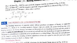
Chapter:8 : Deflection of Beams, , 461, , Example 8.35. A cantilever beam of4m span carries a U.D.L of 3 kNm over its entire span, a noint load of 3 kN at free end. If the same beam is simply supported at two ends, what point, at the centre should it carry to have same deflection as the cantilever ?, , ande, , load, , Solution. Given:, , l=4m, , Length,, , U.D.L., , W= 3 kN/m, , Total U.D.L.,, , W=w xl=3 x4 = 12 kN, , W =3 kN, , Point load,, , Ist case: Cantilever:, , Maximum deflection at the free end,, Deflection, , yM, , due to W+ deflection due to W,, , W, , WP, , 8EI, , 3EI, , .), 2nd Case : Simply supported beam:, Let W be the central point load on the simply supported beam which produces same deflection, as in the case of cantilever., , max, , Then,, , w, 48EI, , Equating (i) and (i), we get, maxy max (given), , 2.5, Of,, , w3, 48 EI, , EI, , W 2.5 x 48 120 kN, , From which, , Thus point load at the centre W =120 kN, , (Ans.), , Example 8.36. A steel tube cantilever 4m long has outside diameter 120 mm and thickness, 0mm. It carries a uniformly distributed load wkN/mfor 3mfrom the fixed end. Find w and deflection, the free end if the maximum stress due to bending is, , 7, , x, , 10* kN/m>., , Take: E = 2.1 x 10* kN/hm2., Solution. Refer Fig. 8.54., , Given: Length,, Loaded length,, , a = 3m, , Outside diameter,, , D = 120 mm =0.12 m, , Thickness,, , t, , l= 4 m, , 10 mm = 0.01 m, , d =D- 21 = 120-2x10 100 mm 0.1 m, Moment of inertia,, (D"-d") = [(0.12) - (0.11'] =5.27 x10 m, =, , Inside diameter, , 64, U.D.L. = w kN/m, , Total U.D.L.,, , Bending stress,, , W=w x 3 =3 wkN, , o=7x 10*kN/m2, , 64, , =
Page 17 :
462, , Strength of, , Materials, w kN/m, , B, 3 m4 m(a) Loaded cantilever, , T =(3 x 3/4+1) mn, , 4.5, , W, , (b) B.M. diagram, , Reference, line, mar, mar, , (c) Elastic curve, Fig. 8.54, , U.D.L., w:, Bending moment at the fixed end, , Wx33w X =4.5 wkNm, 2, MOp We get., M, , Using equation,, , M =, , Op.1, 7x10*x 5.27 x 10⁶, 0.06, , =, , 6.148 kNm, , Equating (i) and (ii), we get, , y = 0.12 0.06m, , 4.5 w = 6.148, , From which., , W, , =, , 6.148, or, 4.5, , w = 1.36 kN/m, , (Ans.), , SIMPLY SUPPORTED BEAMS, Example, , 8.37. A wooden beam 150 mm wide and, 250 mm deep has a span, f 4metne, . Take, Determine the load, that can be placed at its centre to cause the, beama deflection of 12 m, E = 6 x 10 kN/m2., Also find the maximum, , slope., , Solution. Given: Span, l = 4m, Y m a r 2 mm = 0.012 m, Deflection,, Width of the section, b= 150 mm =0.15 m
Page 18 :
Chapter: 8 Deflection of Beams, d= 250, , Deoth ofthe section,, Moment, , of inertia,, , =0.25, , mm, , 463, , m, , _Dd0.15, , x 0.25, , 12, , 12, , = 1.953 x 10- m, , Central load, W:, , Using the, , W, , ymax, , relation,, , with usual notations,, , 48EI, , we, , get,, , Wx4, , 0.012, , 48 x 6x 10° x 1.953x 10⁴, , 0.012x 48 x 6 x 10"x 1.953 x 10⁴, , Or, , W=, , or,, , W=10.55 kN (Ans.), , 4, , Maximum slope, pax, Using the relation:, , 8max, , 16EI, , 0.009, , Or,, , 10.55 x 42, , wI, , 16 x6 x 10°x1.953 x 10, , radian (Ans.), , max, , Example 8.38. A timber beam of rectangular section 10 cm wide and 25 cm deep is simpl, , supported over a span of 4m. What uniformly distributed load in, produce a central deflection of 0.6 cm? Calculate the slope also., , kN/m should the beam carry to, , Take: E = 11 GN/m?, Solution. Given: Length of span,, l= 4 m, , Central deflection, yy0.6 cm =0.6 x 10, Width of section,, , b 10 cm, , Depth of the section,, , d=25 cm, , Moment of inertia,, , I =, , m, , bd3 10x25, 12, , 12, , = 13020.8 cm* = 13020.8 x 10, , Young's modulus,, , m, , E= 11 GN/m2, , U.D.L., w in kN/m:, 5W, , Using the relation: Ymax 384 EI, , get,, , where, W= wl (=w x 4) kN]], , 0.6x 102=., , 5(w x4x 1000) x (4)*, , 384 x 11x 10x 13020.8 x 10*, , Or,, OX,, , W=, , 0.6 x 102x 384 x11x 10"x 13020.8 x 103, 5x 4x 1000 x (4)*, , w = 2.578 kN/m (Ans.)
Page 19 :
464, , Strength of Materials, , Maximum slope, 6,max, , W, , Using the relation:, , we get,, , 24E, , -(2.578 x 100 x 4)x4, , ma, , 24x11x 10'x13020.8 x 10, , Or,, , PTax0.004799 radian (Ans.), 4m long, carries total, of, 40 kN anda concentrated, load of 70 kN at mid I-section,, uniform lon, span., (i) Find the maximum, deflection of the beam., (ii) Ifpermissible, deflection is limited toc0 of the span, is this beam, 360, acceptable baseda, deflection?, Example 8.39. A simply supported beam, , (ii) Find slope, , Take, , at, , E, , =, , I, , =, , the ends., 2.1 x 10, 8.98, , Length, , 70 kN, 40 kN, , kN/r:, , 10- m, , x, , Solution. Refer Fig. 8.55., Given., , a, , 2 m-, , 2 m, 4 m, , of span,, , =, , 4m, , Total uniform load, Mid span load., , Young's modulus,, , W, , = 70 kN, , =2.1, , E, , Moment of inertia,, I, () Maximum deflection, We know that,, , m, , W 40 kN, , yas, , =, , 8.98, of the, , Fig. 8.55, 10* KN/m, , x, x, , 10 m, , beam, y,ar, , Deflection due, _ 5W, 384 EI, , load W+, WPP, to, , 48 EI EI 384, , deflection due to W, 48, , Shaft as shown above behaves like a beam with different loads acting at different pulley
Page 20 :
465, , Chapter: 8 : Deflection of Beams, , b43, 2.1x, , The, , X40, , +48, , = 0.006717 m =6.717 mm (Ans.), , max, the, ci) Is, , 108x 8.98 x 10-5384, , beam acceptable?, , deflection is, maximum permissible, 4, , y==, 360, , Since, , the beam is, , actual yax6.T17mm,, , at, (ii) Slope, , the, , 360, , end, ma, , 0.01111m =11.l1mm, , acceptable, based on deflection. (Ans.), , Slope due to W+slope due to W, , We know that, , W, , W, 16E, , 24 EI, , EI, , 24, , 42, 2.1x 108x 8.98 x10}, , 16, 70, , (24* 16, , 0.005126 radian (Ans.), or,, , Example 8.40. A, , beam, , the, the left end. Calculate, maximum deflection., , 40 kNat a, of 4m span is carrying a point load of under the, , slope, , the, , wo, , supports and deflection, , El = 2.6 x 10' N-m., , Take:, Solution. Refer to, , at, , Fig., , 8-56., , 40 kN, B, a, , b=lm-, , = 3 m1-, , 4 mFig. 8.56, , Given: Length of span,, , Magnitude of point load,, , I= 4 m, W, , 40 kN, , Distance between load and left end,, a = 3 m, , Distance, , b=4-3, , Value of El = 2-6 x 10' N-m, , Slope at A, 0, Using the relation:, , 1m, , =, , Wb, , -b), with usual notations, we get,, , 6A, 40, , x, , 1000 x1_ (42-12, , 6x 2-6x10'x 4, , or,, , 0-0009615 radian, , (Ans.), , Slope at B, 0g:, Using the relation, , B, , EI, , -a),, , weget,, , (40x1000)x (4-3), , 6x2.6xK10, , 4, , of, , distance, 3mfrom, load. Also calculate
Page 21 :
466, , Strength of Materials, or,, , 0-001346 radian (Ans.), , Deflection under the load, y, , Using, , the, , Yc, , Wab, (40x1000)x3x1x, , y, , 0-001154, , c 6 ELL ?-a- b), we get, , relation,, , ycm, , or,, , Maximum deflection, mar, Using the relation,, , 6x 2-6x 10'x 4, m, , =, , (4-3-1), , 1-154 mm (Ans.), , Wa, , max, , 93 EIT-ay"i, we get,, (40 x 1000) x3, , Ymax, , x2-6x, , or,, , =, , mar, , 0-00137, , m, , 10'x 4 (4*-3 3/2, =1:37 mm (Ans.), (wide) x 240 mm (deep), , Example 8-41. A rectangular beam 150 mm, the ends on a span, is simply, supponed a, of 4 m and carries a uniformly distributed load, kN/m, on whole, of 4, point load at the centre should it carry so that, span. What, maximum deflection is doubled ?, Solution. Given: Length,, l=4 m, , U.D.L, , W= 4 kN/m, , Total U.D.L.,, , W=wx l=4 x4 = 16 kN, =, 150 mm x 250, , Cross-section of the beam, Let,, , W =Point, , load, , mm =0-15 mx0-25 m, , at, , deflection., , Deflection due to U.D.L.,, , But,, , 384 EI, the centre,, , at, , ymax, , produce doublete, , 5W, , ymax, , Deflection due to point load, , the centre which will, , 48 EI, , ym a x 2 y, , ..(Give), , 5W, 2x, , 48 EI, , 384 EI, , =2, 48 EI, , y x16x, 384 EI, , W 2xX16x48, 384, 20 kN, , = 20 kN, , Hence, the point load at the centre, (Ans.), Example 8:42. A simply supported beam 5 m, widt, of, span has, and 250 mm deep. The beam carries a point load, section 150 nthe, rectangular, f 10 kN at its centre and the deflection, centre is 12-5 mm. Neglecting the self-weight of the beam, calculate:, (i) Young's modulus;, =, , (i), , Slope at supports., , Solution. Given: Length,, , =5 m
Page 22 :
Chapter: 8 : Deflection of Beams, Width,, , Depth,, Moment, , b, , 150 mm =0:15 m, , d, , 250 mm = 025 m, , 467, , bd, , of inerti /, , 12, , 0-15x0-25, , 1.953, , =, , 12, , x, , 10 m, , W10 kN, , Point load,, , Deflection at the centre,, ymax= 125 mm = 0-0125 m, , Young's modulus, E, , ), , W, Using the relatio Jmar, , 4R EI we get, , 10x5, , 0-0125 =, , 48 x Ex1.953 x10, E, , or,, , 10x 5, , =, , 0-0125 x 48 x1-953 x 104, , E = 1-06 x 10* kN/m2 (Ans.), , OI,, , () Slope at each support, 6, Using the relation,, W2, , 16 EIWe get, , STO, , 10x5, 16x 1-06 x 10*x 1.953 x 10, , 0-000754 radian (Ans.), , Of,, , Example 8-43. A simply supported beam 5 m long carries concentrated loads of 10 kN each, at points I m, from the ends., , Calculate:, (i) Maximum slope and deflection of the beam, and, , (i) Slope and deflection under each load., Take: El = 12 x 10* kNm?., , Solution. Refer to Fig. 8-57., Given: Length,, , =5m, , wo concentrated loads: 10 kN,each, , El = 1-2 x 10* kNm2, , i) Maximum slope,, 6,na, , Using the relation,, , AWe, , nax, , axEl, , (where, A = area of B.M.D. between E and B), , get, , (area klm, , + area, , lpnm), , = 0-001666 radian (Ans.), , max, , =, , xix 10+10x1-5, , 1:2x10|2
 Learn better on this topic