Page 1 :
Chapter, , Deflection of, , 8, , BeamsS, 8.1. Introduction., , 8.2. Beam deflection., 8.3. Relation between slope,, deflection and radius of, curvature., , 8.4. Sign conventions., 8.5. Slope and deflection at a, section., , 8.6. Double integration method., 8.7. Macaulay's method, 8.8. Moment, , area, , method-, , Determination of maximum, slope and deflection in, important cases., , 8.1 INTRODUCTION, , 8.9. Conjugate beam method., , It is observed that when a beam or a cantilever is, subjected to some type of loading it deflects from its initial, , original position. The amount of deflection depends upon, , s cross-section and bending moment. These days strength, and sriffness are the two main design criteria for a beam or a, , cantilever., criterion of the beam design,, the beam should be adequately strong to resist shear force, bending moment. In other words the beam should be, nd, 40Ie to resist shear stresses and bending stresses. But accord-, , According, , to, , strength, , ng to stiffness (being mathematically calculated as, , W, , where, , 15 the applied load and 8 is the maximum deflection or, , design, which is equally imporant, the beam should be adequately stiff to resist deflection., , S49) criterion of the, , Other words,, , beam, , the beam should be, , stiff enough not, , to de, , Jlect more than the permissible limit., , 8.2. BEAM DEFLECTION, When, , a, , load is, , placed, , on a, , beam the bcam tends to, , 8.10. Propped cantilevers and, beams. Typical Examples-, , Highlights-Objectives Type, Questions-Unsolved, , Examples.
Page 2 :
400, defect, , Strength, , of Materials, , sag as shown in Fig. 8.1. Deflection plays a significant role in the design of, structue, tures e, machines, If floor beams, or joists deflect too far, the plaster on the ceiling under them, mav, Although no damage to the structure may result, the apppearance on the ceiling may be, ruined, a floor, supported by such beams may be so out of level that its usefulness for machinery, or, , may, , impaired., , Under load the neutral axis becomes a curved line and is called the elastic curve., The detles, yis vertical distance between a point on the elastic curve and the unloaded neutral aris, jlechon, (a) Beam without load, , Unloaded neutral, axis, , W, mar, , (b) Beam with load, , Elastic curve, , Fig. 8.1, , Fig. 8.2, , 8.3. RELATION BETWEEN SLOPE, DEFLECTION AND RADIUS CURVATUR, Fig. 8.3 shows a small portion AB of a beam bent into an arc., , Let,, , ds = Length of beam AB., , C, , Centre of the are (into which the, beam has been bent),, , a = Angle which the tangent at A makes, , with XX-axis, and, a+, , da, , =, , Angle which the tangent at B makes, , Fdr, , with XX-axis., We find, from the geometry of the figure, that, LACB = da and ds = R da., , or,, , A, , dr, , (assuming ds =dx), , R, , O, ..(i), , dx, , + da, , Fig.8.3, , If the co-ordinates of point A are, x and y, then, , dy or a=, , tan, , dx, , dx, , (taking tan a = a since, , o is very small), , Differentiating the above equation w.r.t. x, we get, , dody, dx, , d, , d, daas, dx, , Also we know that,, , at, , ), lC engine., Connecting rod and crankshaft of an
Page 3 :
Chapter:8 Deflection of Beams, , Nowsubstituting, , 401, , or M= Ex, i n the above equation we gct,, , d, M =EI dy, , ...(8.1), d2, The above equation is based only on bending moment (effect of shear force, being very small,, has been neglected), , 8.4., , SIGN CONVENTIONS, , To find out the slope and deflection of a centre line of a beam at any point proper sign conventions, will have to be taken into account, the following sign conventions will be used:, , 8.5., , 1., , x is positive when measured towards right., , 2., , y is negative when measured downwards., , 3., , M, , 4, , Slope is negative when the rotation is clockwise., , (bending moment) is negative when hogging, , SLOPE AND DEFLECTION AT A SECTION, , The important methods used for finding out the slope and deflection at a section in a loaded, , beam are discussed as follows, 1. Double integration method., 2., 3., , Moment area method., Macaulay's method., The first two methods are suitable for a single load, whereas the last one is suitable for, , several loads., "Moment area method" is more useful as compared to double integral method because, many problems which do not have a simple mathematical solution can be simplified by the bending, , moment area method., , 8.6. DOUBLE, , INTEGRATION METHOD, , Cantilevers:, Case I. Cantilever beamConcentrated load at free end:, , Fig. 8.4 shows cantilever with, a concentrated load W acting at free, , ma, X, , end., Let the moment of inertia of, the section of the cantilever about the, neutral axis be I. Consider a section, AX at a distance x from the fixed end, , -, , =, , -W(, , -, , x), , EI 4= -W - x), dx, , -, , -(), , Fig.8.4, , A., , M,, , x
Page 4 :
402, , Strength of Materials, Integrating, we get, , El-w, dx, , (where, C = constant of integration), At A (fixed end):, , =, , 0 and = 0, , C =0, , -w x, , El, , -, , . ) Slope equation, Slope at B: Putting x =l, we have, , dy, , dx, , Open, , WI, , view of an IC engine crankcase., , 2 EI, , i.e, , ..8.2), , 2 El, , To get deflection, integrating eqn. (i) above, we get, , Ely =-W, , (where, C, = constant ofintegratio, , AtA (fixed end):, x= 0 and y = 0, C, , = 0, , Ely=-W, , .(ii) Deflection equaton, , Deflection at B: Putting x = l, we get, , -E, , W, EI, , Downward deflection of B = W, 3 EI, , The eqns. (8.2) and (8.3) give, , W, , X, , maximum values of slope and deflection, at the free end., , -, , ), , -, , A, , c, , Case II. Cantilever of length, carryinga concentrated load, , Wat dis-, , ance a from the lixed end:, Refer Fig. 8.5. Consider a section, XX at a distance x from the fixed end A., , M,, Eld, , W(a -x), -W(a - x), =-, , -(a-x)X, Fig. 8.5, , dx, ation, , Integrating, we get, , EI, , (where,, , C,, , =, , constant of integr
Page 5 :
Chapter: 8 :Deflection of Beams, , 403, , At fixed end A: x = 0, = 0, C =0, , .i) Stope equation, Slope at C: Putting r =a, we get, , .a, , -, , 2 EI, , Wa, .E, , i.e., , As there is no load on the portion BCthere will, e no B.M. in that portion and the portion will not, bend: it shall be straight., , c 2WaEI, , .(8.4), , To get deflection, integrating eqn. (i), we get, , El y= -Ww, (where, C, = constant of integration), , Atfixed end A:, , x, , =, , 0,, , y =0, , C 0, Levers, , El y=-Wa, Deflection at C: Putting x = a, we get, , Wa, 3 El, , Wa, , .(8.5), , Downward deflection at C = :, , 3 EI, , But, y,, , =, , BD, , (Fig. 8.5) and B'D, , BD, But,, , =, , -, , tan, , ec, , =, , BC, , ec, , Since, , is small, therefore tan =, , 0l, , Wa2, , BD +BD'=-Wa, 3EI, B, , =, , Wa, a, , 3 EI, , +, , Va, 2 EI, , Wa, 2EI, , (1- d, , Case III. Cantilever of length I carrying unilormly, , whole length, , x, , a) *2 El, , Yn= BB, , Downward deflection of, , DC', , =, , ..(8.6), distributed load, , Refer Fig. 8.6. Consider a section XX at a distance r from fixed end A., , w, , per unit, , run over
Page 6 :
404, , Strength of Materials, w/unit length, , X, , B, max, , X, , - (-x), , -x, , Fig. 8.6, , M,, or, , =, , w -x, 2, , dx, , Integrating, we get El=+-+, dx, , (where, C = constant of integraion, , G, , r=0, =0, dx, , At fixed end A:, , wl, , C, , ..i) Slope equaton, X=l, we have, , Slope at B: Putting, , El.0 = - 1 ) - " 6 =W, , w, e6E, , i.e., , 6EI, , 6, (where W=w.)..(8., , To get deflection, integrating eqn. (i), we get, , Ely =-, , - W+, , -, , (where, C, = constant ofintegrdu, X=0, y =0, , At the fixed end A:, , 0-24+C, C=, , Hence,, Deflection at B:, , Ely=-d x- 6wr+ w, 24, -, , Puting x = l, we get, , 0-1* "xl+, 6, 24, , Ely, , -, , W, , wl", , 24, , 8, , ...(ii) Deflection eqa
Page 7 :
Chapter : 8, , Deflection of Beams, , W, , 8EI, , 405, , (where, W= wl), , 8E, , Dowmward deflection of B, , W, , ..8.8), , 8 El8 EI, , The eqns. (8.7 and 8.8) give slope and deflection at B which are maximum., , a, , Case IV. Cantilever of length I carrying uniformly distributed load of w per unit run for, distance a trom the fixed end., , X, , at, , Refer Fig.(8.7). Consider a section, a distance x fronm fixed end A., wa -, , M,, , X, w/unit run, B, , x), , 2, , D, , 2, , E4=- W{a-2, d, , Integrating for slope,, , E, , have, , B, dx, , (where, C, , When,, , we, , Fig. 8.7, , constant of integration), y, , x=0.=0, dx, wa, , Hence,, , Wa, , El x, , ...() Slope equation, , 6, , dx, , Slope at C: Putting x=a, we get, , wa, 6 EJ, dx, Since portion BC is not loaded it does not bend and remains straight, therefore,, , (where, W=wa)...(8.9), , El, To get deflection integrating eqn. (i), we get, , w, EI y 2, , When,, , (a-12x)", , xwa, , + C, (where, C, = constant of integration), , 6, , X =0, y =0, 4, , Wa, 24, , Hence,, , EIy, , w (a, , -, , 2 12, , x)", , Wa, , 4, , 24, , 6, , Deflection at C: Putting x = 4, we gel, , E Iy. =, , Wa, , w, , 24, , Wa, , 8, , .i) Deflection equation
Page 8 :
406, , Strength of Materials, , 8E), , (where,, , W=, , W.a)..8, , 4, , CC'= BD = - Wa, , 8 EI, But,, , B'D, , =, , CTD, , = (l, , -, , tan, , 6, , BC, , =, , a))x, , x, , (, , 6c, , tan, , ec, , when, , =, , E, , B D + B'D =, , Bçis sngl, 6E, , -, , El, , +( -a)x-waEl, , 3, , E - a)|, ET6, 8waNaDownward deflection of B, , wa, , 8, , E, , 6, , a), a_(1, E, T -- a), , Wa' Wd o, 2, , -, , Or,, , ..8.l), , 8 EI, , Case V. Cantileverof length l carrying a uniformly distributed load of w per unit run on, a part of span from the free end.:, , It is obvious from the Fig. 8.8 (a. b. c) that to get result in case (a) take the differences ofesut, in case (b) and case (c), thus:, , -(l- a), -, , w/unit run, , c000000000, , B, , (a), w/unit run, , (b), , -(1- a), , w/unit run, , 000 0 0 0O, yB2, , (c), E and I = constant, , Fig. 8.8
Page 10 :
408, , Strength of Materials, C =0, , ., , El, , Hence,, , -M.x, , dx, , ) Slope equi, , Slope at B: Putting x = l, we get, , 4, , Ely=-M.+C, , (where, C,, , constant of, , =, , integrati, , X = 0, y = 0, , When,, , C = 0, , Ely= -MM., , Hence,, , ...(i) Deflection equati, , Deflection at B: Putting x = 1, we get, , Ely =-M, 2, i.e. Downward deflection of B, , =, , B, , MI, 2 El, , MI, , ..8.1, , 2EI, w/unit run, , Case VII. Cantilever of length l carrying a distributed load when intensity varies uniformly from zero at the free end to w, , per unit run at the fixed ends., , Refer Fig. 8.10. Consider a section XX, at a distance x from the fixed end., , Intensity, , -, , of, , loading, , at, , X, , the section XX, , -()-, , ) per unit run, Fig. 8.10, , The B.M. at the section XX,, , M,, , -0-x)x¥(-x)x, , EIdy_ w, , E, , -, , w -), , =-, , 3, , 61, , x*, , 61, , Integrating for slope, we get, ation, , El=4-», 241, , +C, , x =0,=0, , When,, , Hence,, , (where, C, = constant of integr, , El, , =+w, dx, , C,, , )" w, 24!, , =-, , .(1), , Slope, , quan, , 24, , Slope at B: Putting x =l, we get, , w, -dx4, 24 El, dy, , . . ( 8 1 0
Page 11 :
Deflection, , Chapter:8, To, , get deflection, integrating, , Hence., , =, , 0, y, Ely, , have, , Wx+C2, , 1207, =, , we, , 3, , w - x), , Ely, When, , again,, , 0, , C,, , (where,, , 0=-, , ., , +C2 or, , 24, , =, , constant of, , integration), , C2 120, , w3, , =-PU1201, , 409, , of Beams, , ..ii) Deflection equation, , 120, , Deflection at B: Putting r = 1, we get, , ElYB, , 24, , wl, , 120, , -, , wl, or,, , YB, , 30 EI, , of B, ie. Dowmward deflection, , w, , 30 EI, , intensity varies, , a distributed load whose, 1, Case VII. Cantilever of length carrying, the free end:, from zero at the fixed end to w per unit run at, , uni-, , formly, , deflection at, Refer Fig. 8.11. It is obvious that the, , distributed load where, free end, intensity varies uniformly from zero at, end to w per unit run at the fixed end., , |deflection at B, , due to uniformload of w per unit, , Deflection at B, B, , =lydistributed, , run over the whole., , due to, , a, , w/unit run, , Fig. 8.11, , Deflection downward at B,, , Ya, , wl", , YB8EI, , 30 EI, w, , 1120 wl, EI, , WORKED EXAMPLES (Cantilevers), W / u n i t urn, , Example8.1. Acantilever 1.5m long caruniformly distributed load over the entire, , M, , 0 00, , 0 0ONO, , gth. Find the deflection at the free end if the, ope at the, free end is, , 1.5, , Solution. Length of the cantilever,, I= 1.5 m, Slope at the free end,, , =1.5° = 180, , -, , 1.5 radian, , Deflection at B, y, , Slope at the free end, w =180 1.5, 6E, , 1= 1.5 m -, , Fig. 8.12
Page 12 :
410, , Strength of Materials, TtX1.5 x 6, , w, EI, , 180, , 20, , wl, , Deflection at the free end,, , 8EI, =, , 0.02945, , m or, , 29.45, , mm, , 29.45, , mm (Ans.), Example 8.2. A 2 meters long cantilever made of steel tube of section 150 mm, extenala, nal dia, eter and 10 mm thick is loaded as shown in, the fig. 8.13 (a). IfE 200 GN/m2 calculate:, i.e., , =, , i), (ii), , The value of W so that the maximum bending stress is 150 MN/m?, The maximum deflection for the loading., , Steel tube, 2W, , W, 41= 10 mm, , YB, -, , (-a) = 1.5, , TT, , a=0.Sm+, , m-, , d = 130 mm, , - 1 =2 m-, , FD=150mm>, , (a) Cantilever, , (6) Cross-section of the cantilever, , Fig. 8.13, , Solution., Length of the cantilever., , I2 m, External diameter of the steel tube, D = 150 mm = 0.15, Thickness of the tube, , = 10 mm, , Internal diameter of the tube., Maximum bending stress,, , d=D-21= 150 -2 x, , 10, , 130 mm, , =, , 0.13, , o = 150 MN/m2; E = 200 GN/m2, , (i)Load. W (M:, Maximum B.M., , M, , =, , =, , WI, , + 2W (, , -, , a), , W, , =, , (3, , -, , 2a), , W(3x 2-2x0.5) =5W Nm, , I2Dd), , Moment of inertia,, , O.15), , - (0.13), , = 10.8 x 10 m, , Using the bending equation, we have, , o r G, =MXy, I50 x10=Wx (D/2), 10.8 x 10w, , Hence,, , =150x 10° x, , 5W x 0.075, , 10.8 x 10O, , 10.8, 5x 0.075, , W= 43200 N (Ans.), , x, , 10-6, , = 4320 N, , m
Page 13 :
Chapter : 8, The maximum dellection, 8:, ), Total deflection at the free end Deflection at, =, , 411, , Deflection of Beams, , the free end due to the load W alone, , + deflection, , free end due to the load 2 w, at the, , 3 EI, , W3, W, , 3E, , 2W-a, , 2W-aa, 2, , 3EI, , EI, , EI, , 2W-a) W-a).a, EI, , 3 EI, , 3PP+2(1-a, +3 -a.a, 3 EI L, +, 3EI 2, , 612a, , -, , +, , 6la?, , -2a, , +, , 3/'a, , 3 - a ta or 5-, , -6la +3a, , - a ) +a', , 3 EI, , 4320, 10 x 10.8x, , 3x 200x, , 105[3x2"(2-0.5) +0.5°x, , 10, , mm, , = 12.08 mm, Hence, maximum, , deflection, , =, , 12.08, , mm, , (Ans.), , Example 8.3. A cantilever of 3 metres, cross section, length and of uniform rectangular, witha, I50 mm wide and 300 mm deep is loaded, it, 30 kN load at its free end. In addition to this, kN, 20, carries a uniformly distributed load of, Calculate:, per metre run over its entire length,, maximum, (i) The maximum slope and, , deflection., (ii), , The slope and deflection at 2, , metres, , for the fixed end., Take, E = 210 GNIm2, , Steel bars used in, , l, , Length of the cantilever,, , Cross section: width, b, , 150, , =, , mm, , 3, , =, , depth, d= 300 mm =0.3, , 0.15 x 0.3-337.5 x 10, ()Maximum, , Consider, , slope ( , ) , maximum, , a section, , XX at, , a distance x, , (y,nar, fixed end (Fig. 8.14), , deflection, , from the, , 30 kN, X, , 20 kN/m, , AX6O0000000000.00.00.0006.00000.00B, , -2 m-, , -3 m -, , Fig. 8.14, , M,, , =-30(3, , x), , -, , 20(3 x), 2, , m, , m*; E = 210 GN/m, , 12, , 12, , drilling, , m, , 0.15 m;, , =, , hole, , petroleum wells., , (Bombay University), Solution., , deep, , like
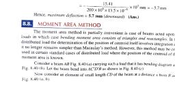
Page 15 :
413, , Chapter: 8 Deflection of Beams, c, , 253.3x10, , 3.3, , 210x10x337.5x10, , EI, , y, , i.e.., , Example 8.4. A 250 mm, , 3.57 mm (downard) (Ans.), 30 mm deep, long cantilever of rectangular section 40 mm wide and, , distributed load., carries a uniformly, , rilever is, , not to exceed, , Take,, , -x10 mm=-3.57 mm, , E, , =, , 0.5, , Calculate the value, , of w if the maximum deflection, , in the, , can-, , mm., , 70 GNin?., , Solution. Length, , of the, , Width., , Depth., , cantilever, l 250 mm 0.25, b 40 mm =0.04 m, d 30 mm =0.03 m, =, , =, , m, , bd0.04x, 0.03=9x10, 12, 12, , Moment of inertia,, , E= 70 GN/m2, , Young's Modulus,, , 0.5, Maximum deflection, yma=, max, Value of w (Nlm run):, , mm, , =, , 0.0005, , m, , w/unit run, , AXOO000000000000000000000B, max, , =0.5 mm, , ]= 250 mm, Fig. 8.15, , Maximum deflection,, , Ymax, , w = 0.0005, , wx (0.25)", or,, , 8x 70x, , 10 x9x10-8, W, , 0:0005, , 0.0005 x 8x 70 x10, , x9x, , 10, , 0.25), 6451 N/m or 6.451 kN/m, w = 6.451 kN/m (Ans)., , Hence,, , and 200 mm, 8.5. A cantilever 2 metres long is of rectangular section 100 mm wide, 1.25 metres, It carries a unifomly distributed load of 2 kN per unit metre length for a length of, Jrom the fixed end a point load of 0.8 kN at the free end. Find the deflection at the free end., , Example, , eep., , Take, E = 10 GN/m., , Solution. Refer to Fig. 8.16., 0.8 kN, ,2 kN/m, , VB, , - a = 1.25 m, , - ( - a ) =0.75 m->, Fig. 8.16
Page 16 :
414, , Strength of Materials, l=2 m, , Length of cantilever,, , b= 100 mm = 0.1 m, , Cross section: width,, , d= 200 mm = 0.2 m, , depth,, , bd0.1x0.2 -66.66 x10 m, , =, , Moment of inertia,, , 12, 12, w=2 kN/m: E = 10 GN/m*, , Deflection at the free end, yp:, , Deflection at the free end B. y, (downward), = Deflection at B due to uniformly distributed load, +deflection at B due to point load atR, , wa8EI, , -, , 10x 10 x 66.66 x 102x 1000x, , 75, 0.8+1000x2|, 3, , 1.25" ,, , [1098.63 + 2133.33], 666.6 x 10, , 4.848 x 10 m = 4.848 mm, , 4.848, , Hence, Example, , 8.6. A 2 metres, , mm (Ans.), , long cantilever of rectangular section 150 mm wide and 300 nn, , deep is loaded as shown in the fig. 8.17. Calculate the deflection at the free end., Take. E = 10.5 GNm?, 1.5 kN, 3 kN/m, , C, , A, , 00d, , B, , a =Im-, , a l m--, , -l=2 m Fig. 8.17, , Solution. Length of the cantilever,, 2m, , Cross section: width,, , depth,, Moment of inertia,, , b= 150 mm = 0.15 m, , d, , 300 mm = 0.3 m, , 0.3, .bd0.15x, I, 12, , 12, , =, , 337.5, , E= 10.5 GN/m2, Young's Modulus,, Deflection at the free end. y, Deflection due to uniformly distributed load at the free end, , x 10 m
Page 17 :
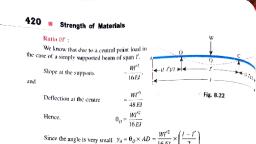
Chapter: 8: Deflection of Beams, , 415, , Piston, piston rings and connecting rod., W, , (3/-4la' + at), 24 E, , (Eqn. 8.13), , 3x 1000, , 24 x10.5x 10x 337.5 x 10-6, , 3x2"-4, , x, , 2x 13+, , 13] x 103 mm, , 35.2 x 106x41 x 1000 =1.443 mm, Deflection at the free end due to point load 1.5 kN, , 1.5x 1000x 2, x, , 3 EI, , 3x 10.5 x 10x 337.5 x 100, , 10 mm=1.128mm, , Total deflection (dowmward) at the free end, a, = Deflection due to uniformly distributed load, +deflection due to the point load, = 1.443 + 1.128 2.57 mm, , 2.57, , Hence,, , mm (Ans.), , SIMPLY SUPPORTED BEAMS, Case I. Simply supported beam of span I carrying a pointload at mid span:, mid span C., Fig. 8.18 shows a simply supported beam AB of span l carrying a point load Wat the, , Since the load is symmetrically applied the, maximum deflection ya) will occur at mid span., , x, , /2, , 2, , W, equals, , Each vertical reaction, , W, , B, , Consider the left half AC of the span., The B.M. at any section XX in AC distant, W/2, from A is given by,, , max, , W/2, X, Fig. 8.18, , d2, Integrating, we get, , E 4yW, dx, , (where,, , C,, , =, , constant, , +C, , of integration)
Page 18 :
416, , Strength of Materials, when,, , 0-012+G, 4, WI, , C, Hence,, , EEl, , 16, , w2, 16, , dr, , .) Slope equation, , Stope at A:Putting x =0, we get, , 6-, , W, 16E, , e, , i.e., , WI, -16 16EI, E, , 8.19), , Integrating the slope equation, we get, , Ely, , Deflection at C:, , W3, , 12, , 16, , x +C2, , C, , X = 0, y =0, , When,, Hence,, , Wr, , 0, , WI2, , W, El y12, , ..(i) Deflection equation, , 16, , Puttingx = /2, we get, , Elyc, , Wx(1/2), , 16, , 12, , W, , W, 96, , W, (1/2), , 9, , Wl, , 48, , W, 48 El, Hence, (downward) deflection of C, , W, , .8.20), , 48 EI, , Simply supported beam of, carrying a uniformly distributed, , Case II., span I, , load of w per unit run over the whole span: A, , X, , w/unit run, , mmmimm, , Fig.8.19 shows a simply supported, beam AB of span carrying a uniformly, distributed load w per unit run over the whole, X, reaction equals, span. Each vertical, Consider a section XX at a distance x, from the end A., , M,, , -, , Fig. 8.19
Page 19 :
Chapter : 8 : Deflection of Beams, , E, , 417, , x-, , Integrating, we get, , El, , W2W, , (where, C = constant of integration), , dx, , The loading being symmetrical, the maximum deflection will occur at mid span and hence the, , slope at, , mid span, , equals, , zero., , ie.,, , -J-G, C, , Or,, , +C, , w, 16, , wl, 48, , 24, , (i) slope equation, , Hence,, Slope at A: Puttingx =0, we get, , EIO, , 24, , ..(8.21), , 24 El, Integrating the slope equation, we get, , Ely=, When,, , x+C (where, C =constant ofintegration), C0, , X= 0, y =0, , w, , wl3, , Ely+1224 24, , Hence,, , (i) Deflection equation, , x, , Deflection at mid span, ymar : Putting x = /2, we get, , Ely+u2)-0/2-/2, 24, 24, wl, 96, , wl, , 5wl, , 384, , 48, , 384, , 5wl", , Ymax, , Hence,, , w, , 384 EI, maximum downward deflection, , Sw, , (8.22), , 384 EI, , WORKED EXAMPLES (Simply Supported Beams), a, supported, Example 8.7. A girder ofuniform section and constant depth isfreely, 15.614 x 100 m*, calculate:, and, of metres., 3, If the point load at the mid span is 30 kN Ixx=, over, , ), , The central deflection., , i), , The, , stopes at the ends of the beam., , Take: E = 200 GN/m, , span