Page 1 :
CHAR, , 1, , Basics of Engineering Materials, , UNITI, Syllabus:, 1.1, , Classification of engineering materials., , 1.2, , Crystal structure, Unit cell and space lattice., Microstructure, types of microscopes., , 1.3, 1.4, , Sample preparation, etching process, types of etchant., , 1.5, , Properties of metals Physical Properties, Mechanical Properties., Hardness testing procedure on Brinell and Rockwell tester., , 1.6, , 1.1, , Classification of Engineering Materials, Engineering materials is the branch of metallurgy which deals with classification,, properties and applications of, materials used in industries. Every product given by industry, every machine in, industry made of metals. Parts made, from metal, composites, polymers, etc. in our homes makes humans life more, comfortable and safe., Solid materials used in engineering field to cater and serve, variety of applications are called as engineering materials., Today's engineering world deals more with alloys of metals than original single, metal. Knowledge of metals and alloys, is undoubtfully essential one for an engineer. To represent importance, and utility and materials, an example of typical, family car is shown in Fig. 1.5.1(Refer Section 1.5) which makes use of, almost all types of metals as well as non-metals., Broad classification of material is given in Table 1.1.1., , Table 1.1.1: Broad classification ofengineering materials, Engineering, , Metals, , materials, , Ceramics, , Plastics, , and other, , Ferrous, , Non-ferrous, , Amorphous, , Steels, , Aluminum, , Stainless steels Copper, Tool and, Titanium, Die steels, Tungsten, Cast irons, Others, , 1.1.1, , Theroplastics, Acrylics, ABS, Nylons, Polyethylene, PVC, Others, , ThermosetsElastomers, Epoxles, Phenolics, Polyimides, Others, , Rubbers, Sillcones, Polyurethanes, , Composites, , Oxldes, Nitrides, Carbides, , Glasses, Glass ceramics, Graphite, , Reinforced, Plastics, Metal-matrix, Ceramic-matrix, Laminates, , Diamond, , Classification of Materials as Amorphous and Crystalline, Ferrous and Non Ferrous, , Solids have greater inter atomic attractions than liquids and gases. However, there, are wide variations in the, properties of solid materials used for engineering purposes. The properties of materials depend on their, interatomic, , bonds. These same bonds also dictate the space between the configurations of atoms in solids.
Page 2 :
VIglcnGal, , Classification of materials based on arrangement, of atoms in, , Metals can also be classified as, Classification of metal, , solid, Engineering materials, Classification based, , 1) 1)Ferrous, , on, , 2) Non-Ferrous, , arrangement of atoms, , 22000, , 9220200000000, , Fig. C 1.2, Amorphous, , Crystalline, , materials, , materials, , Metals can be grouped into ferrous and non ferrous, metals, 1., , No definite arrangement, , of atoms and, , Atoms have, definite arrangement, in the crystal structure, , no, , orystal structure, , Glass, Plastics, Rubber, All, , Ferrous: These materials contain iron, , as their, , main constituent. Examples of ferrous, , metals, , are, , iron and steel., 2., , Major metals and alloys, , Non-ferrous: These materials contain substances, other than iron as their main constituent., Examples of non-ferrous metals are aluminum,, lead, and zinc., , solids may be classified as, , Classification of ferrous metals, , Classification of solid, , Ferrous metals, , 1) Amorphous, , Steel, , Cast iron, , 2) Crystalline, Low alloy, , Fig. C 1.1, 1., , steel, , Gray, , White, , Alloy, , steel, , cast, , cast, , cast, , iron, , iron, , iron, , Amorphous, , Amorphous materials have no regular arrangement of, their molecules. Materials like glass and paraffin, are, considered amorphous. Amorphous materials have, the, properties of solids., They have definite shape and volume, and diffuse, slowly. These materials also lack sharply, , defined melting, , points., In many respects,, , they resemble liquids that flow very, slowly at room temperature., 2., , High alloy, , Crystailine, In a crystalline, , structure, the atoms are, arranged in a, three-dimensional array, called a lattice. The, lattice has a, regular repeating configuration, in all directions. A, group of, particles from one part of, a crystal has exactly, the same, geometric relationship as a group, from any other part, of, thesame crystal., , Low, , Medium, , carbon, steel, , High, , carbon, steel, , carbon, steel, , 1.2, , Ductile Malleable, , cast, , cast, , iron, , iron, , Crystal Structure, , Definition:A crystalis defined, , as an orderly array of ato, of solid has periodically repeateed, arrangement of atoms. Normally, metals are made up, number of crystals and, each crystal consists o, number of atoms., in space. Crystalline form, , Crystal structure is, the atomic arrangement, These are regular geometric, positions of atoms, , in, , > olids., , in, , spa, , These positions are the, result of the directional bond, and/or close packing of atoms. With the minimum ener, per unit volume the crystal, stable, structure will have Sto, arrangement, and then this arrangement can, a. Preserve electrical neutrality., , ., , C., , Minimize strong ion-ion repulsion., Satisfy the directionality.
Page 3 :
d., , Minimize discreteness of all covalent bonds., , e, , Packing the atoms closely., , Polymorphism is the ability of a solid material to exist, in more than one form or crystal structure., , Most of the important metals crystallize in either the, cubic or hexagonal systems and only three types, of, space lattices are commonly encountered,, , Types of Space Lattices, (a) BCC (body-centred cubic), wwww, , (b) FCC (face-centred cubic) and, wwwww.ww, , Rwww.w., , wwwwww.www.wwwwwwwwww.www, , (c) CPH (close-packed hexagonal), www.swssoowc, o, , Fig. C 1.3, , The unit cell of the BCC structure contains:, 8 atoms at the corners x 1/8, 1, , center atom, Total, , =, , 1, , atom, , 1, , atom, , 2 atoms, , Examples of metals that crystallize in the BCC structure, , are chromium, tungsten, alpha (o) iro, delta (6) iron,, molybdenum, vanadium and sodium., , (b) Face Centred Cubic (FCC), There is one atom in the center of each face of the, cube along with eight corner atoms. Each face atom, touches its nearest corner atom., The unit cellcontainsS:, 8 atoms at the, , cornersx 1/8, , 6 atoms at the faces x 1/2, , Total, , 1, , atom, , 3, , atom, , 4 atoms, , Fig. 1.2.1: Space lattice illustrating lattice parameters, , When a molten metal or alloy solidifies the atoms take, up a definite geometrical arrangement and this is the, , fundamental difference between the crystalline form, and the liquid or vapour state., (a) Body Centered Cubic (BCC), Each corner atom is shared by eight adjoining cubes, , and the atom in the center cannot be shared by any, , other cube., , Fig. 1.2.3 : FCC unit cell, Total 4 atoms indicate that the FCC structure is more, densely packed than the BCC structure., Examples of metals that crystallize in the FCC, structure, are aluminium, nickel, copper, gold, silver, lead,, platinum and gamma (y) iron., , (c) Hexagonal-Close Packed (HCP):, Usually the hexagonal close packed lattice, shows two, , basal planes in the form of regular hexagons, with an, atom at each corner of the hexagon and one atom at, , the centre. In addition to this, there are three atoms in, the form of a triangle mid-way between the two basal, planes., It may, , not be readily apparent from the unit cell why, the structure is called hexagonal., If a, , number of these unit cells are packed together, with axes parallel to one another, as in space lattice, a, hexagonal prism may be carved out of them., , Fig.1.2.2:BCC unit cell, , Since each atom at corner of the unit cell is shared by
Page 4 :
Mechanical Engineering Materials (MSBTE), , 1-4, , eight adjoining cells and one atom inside the cell, cannot be shared hence it has total 2 atoms if 3 cells, are considered then it has total 6 atoms., , Basics of Engineeriny, , appearance of any other lattice, the, to, same, will be the, this is, the same direction,, point when viewed in, identical surrounding8, , A point lattice, , -Unit cell, , 120, Fig. 1.2.4: HCP unit cell, , Examples of metals that crystallize in this structure are, magnesium, beryllium, zinc, cadmium and hafnium., , Number of atoms in an unit cel, N, , Where, N, , =, , Average number of atoms in an unit cell., , Ne = Number, , N, , =, , Nin, , 1.2.1, , of corner atoms., , Number of face/base atoms., Number of interior or centered atoms., , Unit Cell and Space Lattice, , Unit cell, , a, Fig. 1.2.5: Representation of part of, a unit cell outlined, , space lattice with, , 1.2.2 Concept of Packing Efficiency, the attraction between the, atoms. Because they attract one another it is often, favorable to have many neighbors. Thus, the coordination, number, or number of adjacent atoms, is important., The reason crystals form is, , The packing efficiency is the fraction of the crystal (or, unit cell) actually occupied by the atoms. It must always be, less than 100% because it is impossible to pack atoms, , without having some empty space between them., , Definition: Packing efficieney is the percentage of total, by the particles., It is also called as atomic, crystalline solids indicates that packing factor, , The atomic order in, small groups of atoms form a repetitive pattern. Thus, in, describing crystal structures, it is often convenient to, subdivide the structure into small repeat entities called unit, cells. The smallest component of the lattice structure is, known as unit cell. Fig. 1.2.5 shows cubical unit cell., , space filled, , Packing efficiency Volume occupied byatoms in unit cell(v), Total volume of the unit cell (V), , Packing efficiency for BCC structure, , The unit cell takes up the shape of parallelepiped. It, has six faces. The lengths a, b and c and angles a, ß and y, are known as lattice parameters. Thus, the unit cell is the, basic structural unit or building block of the crystal, structure and defines the crystal structure by virtue of its, geometry and the atom positions within., , Space lattice, lattice is defined as a 3D geometrical, construction which indicates the arrangements of, molecules in the crystalline solid. It is also known as, the point lattice. It is as shown in Fig. 1.2.5., Space, , Fig. 1.2.6: BCC (Arrangement, , of atoms), , From Fig. 1.2.6., , Volume of unit cell, , =, , a, , Volume of an atom, = 4/3 Ttr, , Each point in the lattice has identical surrounding and, such points are called lattice points. The appearance of, , but,, , a lattice point when viewed in a particular direction, , and, , UW2= Uv? + VW2, UR, , =, , UW?+ WR2, , 100, 00
Page 5 :
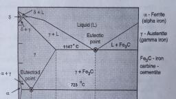
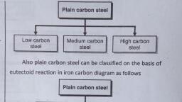
(2a)+a ("UW= a +a), , 4r2, , 4, , Atomic packing factor=, , Volume Occupied, Total volume, , 2x4/3 y3, a, , 0.68 = 68%, , =, , of material science, metals and alloys. It is the branch, macroscopic examination, deals with microscopic and, of metals and alloys., highly depend on their, The properties of metals are, , determine the, structures. The internal structure, application with the, performance of metal under given, examination of, help of metallurgical microscope, the, metals and alloys, , is, , done., , Introduction to Steels and Cast Irons as Alloys of, Iron and Carbon, , study the structural, The purpose of examination is to, constituents in, characteristics of metals and alloys and, , structural, Pure iron is not suitable for use as a, material. It is weak, soft, is very ductile and does not, , properties., relation to their physical and mechanical, , respond to heat treatment to any appreciable degree., a few, Steel, which is basically iron, alloyed with carbon and, elements, percent to a few tens of percent of other alloying, , treated to a wide range of strengths, toughness, , can be heat, , and ductilities., , the most important of these alloying, and, elements in terms of the mechanical properties of steel, primarily on, most heat treatments of steel are based, Carbon, , is, , controlling the distribution of carbon., an alloy of iron and carbon. The carbon, The amount of, content in steel varies upto 1.5 percent., properties. In, carbon in steel has a significant effect on the, small amounts, addition to carbon, steels generally contain, manganese. Carbon, of sulphur, phosphorus, silicon and, chemically, present in steel is in the form of compound i.e. it, Steel, , is, , combines with iron., , respect to, The steels may differ from cast iron with, iron and, percentage of carbon. Cast iron is also an alloy of, 1.8% to, carbon but, percentage of carbon ranges from, form of, 4.2%. In cast iron, there is a free carbon in the, 8raphite in its composition., classified, On the basis of carbon content, steels can be, high, as low carbon steels, medium carbon steels and, carbon steels,, as cast irons can be classified as white, where, cast iron, gray cast iron, ductile cast iron, etc. Further, details of cast iron and steel will be discussed in the chapter, of steel and cast iron., , 1.3, , Metallography, , Microstructure, defects within the, The arrangement of phases and, metal is known as microstructure., observed after, the structure of a metal or alloy, a high degree of, etching and polishing under, It is, , magnification., , maximum at, The magnification is above 25X and, , Microstructural, , 2000X., , Metallography, , is, , is, , generally, , performed using optical or electron microscopes to, magnify features of the metal under analysis., simple words, microstructure is what we see under, metallurgical microscope on nano-scale., In, , Microstructure determine the physical, chemical and, mechanical properties of metals and alloys., Metals and alloys are poly crystalline. It consists of, crystals in the form of grains. The size, shape and, , configuration of the grains within a metal or an alloy, are function of production process and application of, metal, , in, , focus., , The metallographic examination of, , specimen aims to observe and record these crystalline, structures and to interpret from them the history of, , manufacture and use of the metal or alloy., , Types of microscope, Microscopes are required for the examination of the, microstructure of the metal and alloys. A microscope is, an instrument capable of producing a magnified image, , of a small object., , the study of the microstructure of, , Examination
Page 6 :
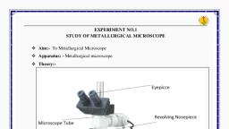
Mecnanical engineering Materials VMSDIE, , Construction, , The main types of microscopes are as follows:, , The table type optical, , Types of Microscopes, , microscope consists of following, , major elements., , Microscope, Elements of Optical, (a) Optical microscope, 1., , (c) Scanning probe microscope, , 2. Tubes, , (d) X-ray microscope, Ultrasonic, , 3. Focus adjustment, , microscope, , 4. Objective, , Fig. C 1.4, , 5. Eyepiece, , (a) Optical microscope, The main principle of optical microscope is to pass a, light through or onto the surface of a specimen and, examine it under magnification., The main components of optical microscope are, objective lense, eyepiece, condenser and light source., The function of each component, , is, , Fig. C 1.5, 1., , (b) Eypiece, , It, , 2., , as follows., , enlarges the image but does not, , increase the resolution., If, , Condenser:, , 3., , It, , an, The vertically movable tube contains, Tubes, eyepiece, objective and plane reflector. The tube, length varies from 160 mm to 250 mm, , Focus adjustment: The limbs of microscope carries, the two knobs for course and fine adjustment., , 4., , Objective : The objective lense is fitted down at the, end of the tube. It helps in a quick resolving the, structure of specimen. It collects light diffracted by the, specimen and forms a magnified real image at the, intermediate plane near eye piece., , 5., , Eyepiece: The primary image can be enlarged with the, help of eyepiece. The eyepiece are available in, , focuses the light source on to the, , specimen for uniform llumination., Eye, , Eyepiece, , State: A flat movable table supporting specimen., can be adjusted vertically up or down., , (a) Objective lense: It magnifies the object, , (c), , State, , (b) Electron microscope, , different magnifying powers such as 5X, 1OX, 15X etc., , Working, ---, , First image plane, , The illuminating light beam is transmitted, through a, , Plane, , Light, , glass, reflector, , source, , condenser, lense, , Objective lernse, , -Specimen, , Fig. 1.3.1: Principle of optical microscope, , specimen before forming its image. The, image is, formed by contrast between different, features of the, specimen depending, on the illuminating source, deviation of the incident light beam, from the, illuminator into the objective lense is, done by plane, glass reflector inclined at 45 angle, to the axis of the, incoming light from the source., Light incident upon, , the specimen is reflected back, from the specimen surface, and pass through the, objective lense and glass reflector, to form the final, image., The enlarged image of, the bright area of the specimen, surface can be obseryed through, the
Page 7 :
(b) Electron microscope, , the detector, these secondary electron converted, into the electrical signals by a photomultiplier., In, , electrical signal is then amplified and displaced on, , cathode Ray tube., Electron gun, , Sample Preparation, , 1.4, Electron beam, , Condenser lense coil, , Sample preparation consists of series of operations, namely sectioning, mounting, grinding polishing and, etching. Each of these stages are described below., , Sectioning, wwwww, , Scanning coil, Objective lense coil, -Display, , Secondary electron, detector, , Specimen, Stage, , Fig. 1.3.2: Principle of electron microscope, , Construction and working, Electron microscopes uses beam of electrons to form, enlarged image of microstructure., optical microscope the light beam is used as a, source of illumination., In, , construction an electron microscope is similar to, that of an optical microscope., In, , The major difference, the type of lense. Here, of, lense, coils are used The whole set up is, instead, enclosed in vacuum. At the top, there is a basic part of, the microscope i.e. source of electrons as a electron, is in, , gun., condensing coil is used to condense the electron, beam and scanning coil is arranged in between, condensingcoil and specimen., , Sectioning is the cutting of small volume of specimen, of convenient size from large volume without any, damage to the microstructure structural changes are, possible while doing cold work or hot work., As possible cutting, , or shearing with hacksaw should be, avoided. So cutting with bonded abrasive wheel and, suitable coolant is the best way to minimize heat and, , deformation, Mounting, It is, , nothing but holding the specimen in a small block, of material usually plasticto ensure further operations, like grinding, polishing etc. Each of the specimen is, mounted by placing it in a mould which is cylindrical in, shape and filing the mould with a suitable material, , that the specimen, operations., , Mounting, , done for two purposes (1) for making, handling convenient. (2) To protect the edgesof, specimen during grinding and polishing, There are two, methods of mounting the specimen, , A, , The electron detector is used to collect the secondary, electrons scattered from specimen., , Working, stream of electrons is formed in high vacuum by the, electron gun. These primary electrons are accelerated, towards the specimen by the anode., The accelerated primary electrons are made incident, on the specimen through the condenser lense coil and, scanning coil. These high speed primary electrons, when falls on the specimen produces low energy, , A, , secondary electrons., , and holds it firmly for further, , is, , Hot mounting, , i) cold mounting, Hot mounting is done by mountinig the specimen, , in a, , cylinder of hard polymer under pressure and elevated, temperature in a moulding press., Moulding material used in this process are, , Thermosets, Bakelite etc., , phenolics, epoxies, diallyl phthalates, , Thermoplastics: Acrylics., need not require pressure and, temperature and is a fast method of mounting. In this, method, the specimen, is placed at the center of metal, Cold, , mounting
Page 8 :
Basics of Engineering Materials, Mechanical, , 1-8, , Engineering Materials(MSBTE, , ring on a glass plate. Liquid moulding material like, epoxides polyesters and acrylics is to be poured into, , the ring to cover the specimen., The ring is then removed after 60 to 90 minutes such, that mounting material solidifies at room temperature, , Grinding, Grinding operation is done to remove scratches let, from previous. Cutting operations. it is one of the most, important, , in, , operation, , grinding procedure, , specimen, , preparation. The, , involves several stages using a, , paper each time. Those are rough, grinding medium grinding and fine grinding., , finer grinding,, , Rough or course grinding is done on a wet belt grinder, with 120 and 240 grit no belts., , removes previous cutting tool marks. The, intermediate stage grinding uses the paper of 240 and, It, , is, , 400 grit no. During the grinding, the specimen, moved backward and forward over the paper until a, , uniform ground finish, , is, , obtained., , then carefully washed under clean tap water, examined and returned to the next grade of paper., Here the specimen should be rotated through 90, before grinding recommences. This process is, repeated for the subsequent grinding operations, rotating the specimen through 90° for each grinding, operation wet grinding is generally applied in medium, , covered surface o, the nylon cloth, firmly in, specimen should be held, rotating wheel. The, polishing wheel, but excessire, contact with the, , It is placed on, , pressure should be avoided., specimen should be rotated or, During polishing the, so as to give an even polish., moved around the wheel, be thoroughly cleaned with, The specimen should, between each wheel., water and dried with alcohol, particle size 0.05, Aluminium oxide AL,O3 powder, for fine polishing., micron and velvet cloth is used, slower speed of 100-150 rpm, Fine polishing is done at, using napped cloth., , should be visible on, After fine polishing, no scratches, and mirror like, the surface and the surface gives shiny, appearance., , Etching, Unetched but polished surface can not be used for, microscopic examination as it does not shows surface, , characteristics such as phases, inclusions, porosity,, cracks, intergrannualar corrosion., , It is, , and fine grinding., For finer grinding the grit size is upto 600 grit., , Eatching, , is, , defined, , as, , the, , process, , to reveal, , microstructural details by selective attack of metal, specimen with an etching reagent,, Eatching reagent, , arte usually dilute acid or dilute, , alkalies in a water alconol or some other solvent. The, , most common type of eacthing is chemical etching., Eatehing is generally done by swabbing or immersion., The choice of a chemical etchant is depend on the, specimen that needs to be etched., , Before etching the surface of the polished specimen, must be cleaned. Nital i.e. nitric acid Alcohol mixture, is the commonly, , used etchant for common irons and, , steels., , stage, Fig. 1.4.1: Grinding directions for each, Polishing, is to remove damage, The purpose of polishing, produced during cutting and grinding and to get, Polishing is done as, scratch free, mirror like surface, Rough polishing is, rough and fine polishing, accomplished primarily with diamond abrasives, 1 microns in the form of oil, ranging from 9 microns to, soluble past., , The etching solution is then applied on the specimen, with dropper or cotton swab. Depending on the, , specimen and nital concentration, etching time vary, from ten seconds to one minutes., After each etching, the specimen should be thoroughiy, washed in running water, followed by drying off with, , alcohol., Tech, , Kauoaledga
Page 9 :
Types of etchants, Types of etchants, (a) Iron and steel, wwwowa, wwwwwwww2*OIIS, a, (b) Copper and brass, wwwwwRwwRe, , (C), , wwwww, , aoo003w3, , Aluminium and alloy, , www.www.wwwwwwwwwwwwwwwwwwwww, , w.k, , (d) Stainless steel, , Fig. C 1.6, Etching reagents for different metals and alloys are, given below., , a., , Iron and steel, (i), , attractive to the designer and if you have been reading, the newspaper, you will know that the new ceramics,, at present under development world wide, are an, emerging class of engineering material which may, permit more efficient heat engines, sharper knives,, and bearings with lower friction., The engineer can combine the best properties of these, materials to make composites which offer especially, attractive packages of properties. And finally one, , should not ignore the natural materials like wood and, leather which have properties which even with the, innovations of toady's materials scientists are hard to, beat., Steel, , Glass, , Etchant, , Nital, , composition, , 1-10 ml Nitric acid, 100 ml ethanol, , (ii), , b., , Etchant, , picral, , Composition, , 2-4 g. picric acid, 100 ml ethanol, , Copper and brass, Etchant, Ferric chloride, gferric chloride, Composition -5, 10 ml hydrochloric acid, 100 ml water., , C., , Aluminium and alloys, Ethant- kellers etch, Composition, , Nitric, , acid -5ml, , Hydrochloric acid - 3ml, Hydrofluoric acid -2ml, Distilled water, , d., , 190 ml., , Stainless steel, Ethant, Composition, , -, , Vilella's Reagent, , Glycerol -45 ml, Nitric acid-15 ml, , Hydrochloric acid-30 ml, , Ethanol-100, , ml, , Rubbe, composite, , Steel frame, , Plastics, , Steel or, Aluminium alloy, , Fig. 1.5.1: Materials used in automobiles, Lets look at an automobile as an example of a common, product that uses a wide variety of materials. These, , materials were selected primarily because, among the, materials that posses the desired properties and, characteristics for the intended functions of specific, parts of the automobile, these were the ones that can, be manufactured at the lowest cost., Steel was the chosen for much of the body because it, is strong, easy to for, and inexpensive. Plastics were, used in many components because of characteristics, such as a wide choice of colors, light weight, and ease, of manufacturing into various shapes at low cost., Glass was chosen for the windows not only because it, is transparent, but also because it is hard, easy to, , shape and clean, and resistant to scratching. Similar, observations can be made for each components of an, automobile, which typically is an assemblage of some, , 15,000 parts, ranging from thin wires to bumpers., , 1.5, , Properties of Metals, More engineering components are made of metals, and alloys than of any other class of solid. But, increasingly, polymers are replacing metals because, they offer a combination of properties which are more, , you need to select, materials to create the product. For selecting, materials, you must assess the properties of each, material tó ensure that the selected material is, appropriate for manufacturing the desired product., While designing a product,, , Techknowledjë, , Pubcations
Page 10 :
Mechanical, , Engineering Materials (MSBTE, , 1-10, , The properties of materials can be categorized into the, , following types:, ii., , Properties of Materials, , (0) Physical, (G) Mechanical, Gii), , Electrical, , (iv), , Chemical, , (), , of materials that have, and tin are examples, Aluminium alloys have medium, low melting points., alloys have a considerably, melting point, and copper, have the highest melting, high melting points. Ceramics, , Physical Properties, , points., , The physical properties of a material refer to the, characteristics that describe the material. These properties, , ii. Specfic heat, temperature, The amount of heat required to raise the, or, of a material by 1°C is called the heat capacity, specific heat of the material., The specific heat of a material is the quantity of heat, , include:, Physical Propertles of a Materlal, , needed to raise the temperature of a unit mass of the, substance, , () Density, , by l'C., , (i) Melting point, , Metals have lower specific heat capacity than plastics., Therefore, they require less heat to reach a paticular, temperature than plastics., , (ii) Specific heat, , expansion, , (v) Thermal conductivity, wwwwwwem, , Fig. C 1.8, I., , Density, Density of material is defined as the mass per unit, volume of the material. Density can be expressed as, Density, , constan, as the fixed or, defined, non-metale, Melting point is, pure metals or, which, temperature at, liquid form., change from solid to, enerpu, material depends on the, a, of, point, The melting, atoms. In addition, the meltine, required to separate its, are made up of, such as alloys that, point of materials,, varies on the basis of their, two or more metals,, Zinc, lead,, , Therma, , (iv) Thermal, , Melting point, , composition., , Fig. C 1.7, , 1.5.1, , the strength of a, is the ratio of, which, strength ratio,, density., material to its, , iv., , Thermal expansion, When thermal energy is added to a material, the, change in its dimension is known as thermai, expansion., Most solid materials expand upon, heating and, contract when cooled. The, change in length witn, temperature for a solid material may, be expressed d, follows, , Mass, , =a,(T-To), , Volume, , Different materials have different density at the same, temperature. For example, metals have higher density, can, than ceramics. In addition, the density of materials, Therefore,, temperature., in, change, with a change, materials can have different density at different, , temperatures., is expressed with, When the density of a material, density., relation to water it is known as specific, in determining the, Density plays a significant role, , or, , o, , AT, , Where l0 and If represent,, respectively, initial andfina, lengths with the temperature, change from To to, The parameter al is, called the linear coefficient, thermal expansion. It is, a material property that, indicative of the, extent to which a material expan, upon heating, and, has units of reciprocal temperatture, C-1 or (°F-1]., Tech, , Kouwledge
Page 11 :
Mechanical Engineering Materials (MSBTE, V., , 1-11, , Basics of Engineering Materials, , Thermal conductivity, , plastic. Some materials, such as rubber, return to, their original shape after the force applied on, , The thermal conductivity is nothing but the mode of, , them, , Mostly the thermal conductivity is denoted by k., , is, , removed. This property of materials is, called elastic strain. Plastic strain results in a, permanent deformation., , transmission from one substance to the other in, the, direction of fall of temperature, but the substance, remain fix at their original position., 2., , Stress, When an external load is applied to a material, the, material resists deforming effects. This interatomic, force F per unit cross sectional area A of a material is, referred as stress., , 1.5.2 Mechanical Properties, Mechanical properties determine the behaviour of, materials when mechanical force is applied to them., , Mathematically, , The study of mechanical properties is essential for, designing and manufacturing purposes., , o, , F/A, , =, , The mechanical properties, of a material refer to, , Stress can be classified into different types depending, , factorssuch as, , on the load that is applied. These stresses are:, , Mechanical Properties, of, , Classification of stress, , Material, , (a) Tensile stress, , (1) Strain, , ww, , (2), , (6) Compressive stress, , Stress, , wwww, , wwwwwww, , (d) Bending stress, , (4) Stiffness, w%, , Fig. C 1.10, , (5) Hardness, , a., , Tensile stress, , b., , Compressive stress: In compressive stress, adjacent, , (6) Toughness, www., , (7) Elasticity, (8) Ductility, , (9) Malleability, , (12) Creep, , (13) Plasticity, wwwe, , Fig. C 1.9, , 1., , tensile stress, two forces pull the, material in opposite directions along the plane of, stress., :, , In, , parts of materials press against each other., C., , Shear stress: In shear stress, parts of materials slide, across each other., , d., , Bending stress: Bending stress is caused when the, , (10) Brittleness, (11) Fatigue, , wwwww.ew, , C) Shear stress, , (3) Strength, , 2ww%, , wwww.ww, , surfaces of materials are exposed to tension and, compression., , For example, when metal is bent,, , tension stretches one surface and the other surface, compressed,, Fig. 1.5.2 displays how, , is, , tensile, compressive, and shear, , stress act on a body., , Strain, Strain is measured as the deformation caused per, unit length in the direction of force applied., , Strain, , is divided, , into two types, elastic and, , Toch, , nouledyo, , PuBlicattaas
Page 12 :
Mechanical, , Engineering Materials (MSBTE, Plastic, , Elastic, , Basics of Engineering Materials, strength is defined as the, , 1-12, , Tensile, Tensile Strength:, resist change caused by external, ability of a material to, stretching., forces, such as pulling and, an object is designed to carry, For example, when, bags, the tensile strength is, heavy weights, such as, considered., , a., , Tension, , b., , Compression, , 777777, , 7777077, C., , Bending, , Compressive strength is the, Compressive Strength:, can resist compressive, extent to which a material, example, bricks have high, stress without freaking. For, they are used to build, compressive strength; therefore, has high compressive, chimneys. Concrete also, used for construction, strength; therefore, it is, purposes., affected by increase in, Yield Strength Strength is, a particular, temperature. The strength of a material at, temperature is known as yield strength., which a, The yield strength of a material is the point at, material deforms and does not retain its original shape, even after external force is removed., , shows stress strain curve, showing various, static strength of material., Fig. 1.5.3, , Shear, , F, , F, Fig. 1.5.2: Types, , d point, , Uitimate o, tensile strength, , ofstresses, , material can experience both tensile and, compressive stress at a time, when in use. For, example, in equipment such as a reactor, the wall is, exposed to tensile stress at different locations. This is, caused by the temperature and pressure exerted by, the fluid against the wall. Compressive stress is applied, on the wall from outside. This is caused due to outside, pressure and temperature., , A, , 3., , 5, Yield, , Stress, , Rupture strength, , strength, Elastic limit, , Proporation limit, , Strength, The strength of a material is its ability to withstand, external forces applied on it during a test or when it is, in use., These forces cause distortion. The resistance to this, distortion is referred to as strength., , Strength of a material, , is of the, , following types, , Types of Strength of a material, (a) Tensile strength, (b) Compressive strength, (c) Yield strength, , Fig. C 1.11, , Strain, , Fig. 1.5.3, 4., , Stress-strain curve, , Stiffness, Stiffness is defined as the, resistance of a material to, elastic deformation. It is also, known as Young's, modulus of elasticity., , Stress, Young's modulus of elasticíty, (E) = Strain, Stiffness and plastic deformation, , are inversely, , proportional. To understand, stiffness, consider an, example of a metal spring. A, spring returns to its, original shape when, the stress applied to it s, removed. This property of a, spring is known a3, stiffness., ulodge
Page 13 :
Mechanical, , Engineering Materials (MSBTE), , Another example of stiffness is the wings of an, airplane, which are required to maintain their shape in, turbulent air., bicycle is yet another example where the frame does, not deform permanently for a long duration because, the material used exhibits high stiffness., , Basics of Engineering Materials, , 1-13, , important that the material you use to create, bridges have high elasticity., It is, , 8., , Ductility, , A, , 5., , Ductility is the ability of a material to resist a high, amount of plastic deformation before breaking under, , tension., , Hardness, The hardness of a material indicates the strength of, , property by which material can be drawn into fine, wires is known as ductility. e.g copper, silver, etc., , the material to resist penetration, abrasion and wear., , Ductility is denoted by percentage elongation, which is, , A, , Tensile strength is directly proportional to hardness., Tensile strength increases with hardness., The hardness of a material must be considered when, making objects such as knives. A knife can be made of, , stainless steel or carbon steel. Carbon steel has high, hardness value. Therefore, knives made from carbon, steel last longer., Diamond is the hardest material and is used to cut, hard materials. Talc is the softest material., Ceramics have high hardness, metals have medium,, and plastics low., , 6, , Toughness, Toughness is the ability of a material to absorb sudden, external pressure that exerts force., It is measured as the energy absorbed per unit volume, of material. In other terms, toughness is the amount of, energy absorbed by a material before it develops a, fracture. A fracture is a crack in the material., When pressure is applied on materials, both elastic, and plastic deformations take place. Therefore,, toughness can also be defined as the sum of elastic, and plastic energy., Toughness is also the ability of a material to resist, with, propagation of cracks in the material. Materials, high resistance to propagation of, high roughness, , offer, cracks when force is applied., , 7., , Elasticity, shape, of a material to return to its original, elasticity., is, called, after the applied load is removed, is, This is measured as the modulus of elasticity that, the ratio of stress and strain., Temperature lowers the modulus of elasticity., Elasticity is an important factor to be considered when, selecting materials for high load applications, such as, The ability, , defined as the maximum elongation or the maximum., The formula to express ductility is given below:, , Percentage elongation, 9., , =Change, , in length of material x 100, Initial length, , Malleability, Malleability is the ability of a material to exhibit, deformation when compressive force is applied., , property by which a material can be beaten into thin, sheets is known as malleability. e.g. plastic, gold, etc, A, , 10. Brittleness, , the property of a material that shows little or no, plastic deformation before fracture when a force is, It is, , applied., Also it is usually said as the opposite of ductility and, , malleability., , 11. Fatigue, Fatigue is defined as the behaviour of a material when, exposed to fluctuating or periodic loads., Fatigue strength is the property of a material to, withstand continuousiy varying and alternating loads., , The level at which the 'fracture occurs when, fluctuating load is applied is lower than the level at, which fracture occurs when static load is applied. The, level at which fracture takes place is referred to as, fatigue failure., , 12. Creep, the permanent plastic deformation of, materials when subjected to constant stress or, prolonged loading usually at high temperatures. Creep, leads to a fracture in the material at static stresses., Creep is nothing but a deformation that occurs overa, Creep, , is, , period of time when a material is subjected to, constant stress at constant temperature., , bridges., Terh, , Kunuladn
Page 14 :
Mechanical Engineering Materials (MSBTE, , 1-14, , Creep, , at room temperature is known as lowtemperature creep. Some materials in which a low, temperature creep may occur are load pipes, roofing, and glass. The occurrence of creep at high, temperature is known as high-temperature creep., In metals, creep usually occurs only at elevated, temperatures. Creep at room temperature is more, common in plastic materials and is called cold flow or, , deformation under load., , Creep curve:, Data obtained in a creep test usually is presented assa, plot of creep vs. time with stress and temperature, constant. Slope of the curve is creep rate and end, point of the curve is Time for Rupture., The creep of a material can be divided into three, stages:, First stage, or primary creep, starts at a rapid rate, and slows with time., , 2, , 3, , Second stage (secondary) creep has a relatively, uniform rate., Third stage (tertiary) creep has an accelerating, creep rate and terminates by failure of material at, , time for rupture., , By careful, the opposite of strength., combination of plasticity and, alloying of metals, the, large structural, strength is used to manufacture, , This property is, , members., , Procedure, 1.6 Hardness Testing, defined as resistance of a material to, scrateches by a hard, penetration or intendation or, material., in determination of, Hardness is qualitative measure, strength of material., repeatable, Hardness tests, in most cases are rapid and, and in many instances non-destructive., Hardness, , is, , Therefore hardness test represents an important, means of quality control. Various methods are, available for hardness measurement., , one are Brinell and Rockwell, hardness tests for metals and alloys., But the most popular, , Brinell Hardness test, The Brinell hardness test is the most commonly, adopted test for hardness of iron, steel brass, bronze, etc. The test is not suitable for hardness measurement, of very hard and brittle material., The principle of operation of this test is to obtain, Brinell Hardness Number (BHN) by the ratio of the, , calculated load and the spherical area of the, Indentation or Impression made on the specimen by, the corresponding indentor ball., 2, Minimum oreep rate, , Time, Fig. 1.5.4: Creep curve, , Procedure, test, a standard hardened steel ball of 10 mm, diameter is impressed on a flat surface of a test, specimen under a load i.e. 3000 kg., , In this, , For brass and soft alloys load used is 500kg. The, load, maintained for 10 to 30 seconds depending upon, , the, , metal being examined., , 13. Plasticity, which retains the, Plasticity is the property of material,, deformation, produced under load permanently. e.g, , D, , gold, silver lead, etc., for forging and, This property of material is important, Material deformation can be, in ornamental work., , deformation is, permanent or temporary. Permanent, irreversible i.e. stays even after removal of the applied, , forces, , Fig. 1.6.1, , :, , Brinell hardness test, , The diameter of the impression, made on the test piece, is measured by a microscope of accuracy, t 0.01mm., is typically 2 to 6 mm.
Page 15 :
Mechanical, , Engineering Materials (MSBTE), , Now the hardness of given sample can be obtained, , mathematically from the following relation., Load on Indentor, BHN Area, of Indentation, , 2P, , TD[D-D2-42], , P, , D, , d, , Types of Indentor, For soft metals, , Steel ball of diameter, 3.mm, , For Hard metals, , Diamond cone Indentor Apex angle, , Types of scales, , Brinell Hardness number, , load applied in kg, Diameter of ball in mm, -, , 1.5 mm or, , 120, , Where, BHN, , Basics of Engineering Materials, , 1-15, , Rockwell, , Diameter of the indentation in mm, , B, , scale, , Rockwell Cscale, , Minor, , Major load, , 10kg, , 100 kg, , 10 kg, , 150 kg, , The Rockwell hardness test, Multiple Choice Questions, for Online Examination, , The Rockwell hardness test is the most widely used, hardness test in industry., The test gives quick and direct results as compared to, other hardness test. In this test Hardness is, determined by the depth of indentation in the test, material resulting from application of a given force on, , Metals are, (a), , Crystaline, , (b), , Amorphous, , (c), , Both, , (d), , None of the above, , Ans.:(a), , a specific indenter., , The depth of penetration, , (1), , is inversely proportional, , to, , the hardness. Hardness values are expressed by, writing the number followed by the letters HR for, Hardness Rockwell and affixing the name of the scale, used., , Principle of operation, , (2), , pure metal only consists of, , A, , (a), , Two elements, , (b), , Single element, , (c), , Three elements, , (d), , Four elements, , Ans.:(b), (3), , P, , Cast irons belongs to, (a), , Non-Ferrous metals (b) Ferrous metals, , (c), , Both, , (d), , None of the above, , Ans.: (b), (4), , (a) Ball inden tor, , (b) Diamond cone, , Fig. 1.6.2 Rockwell hardness principle, :, , cone, applied on steel ball or diamond, When load, load, indentor in two steps i.e. minor load and major, P is, , one after the other., in the test, indentor makes an impression, "h' is measured, specimen. The depth of impression, can be, which gives the hardness value. The hardness, Different scales, read on the dial attached to indentor., are used to measure hardness of different metals and, , The, , alloys, , A, , glass is the most common example of, , (a), , Crystaline solid, , (b), , Amorphous solid, , (c), , Both, , (d), , None of the above, , Ans.: (b), (5), , Metals has fixed melting point, (a), , True, , (b) False, , Ans.:(a), (6), , Copper and aluminium are the examples of, (a), , Non-Ferrous metals (b) Ferrous metals, , (c), , Both, , Ans.:(a), , (d) None of the above