Notes of 2nd Year Diploma(4 thSem), Geotech & Hydraulics & Theory Of Structure & RCC And Steel Design & Advanved Surveying Simple Stress & Strain.pdf - Study Material
Page 1 :
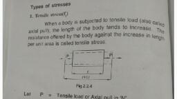
1, SIMPLE STRESS AND STRAIN, force. It is observed that for a, removal of the external, , Simple Stress and Strain, , original shape or size after, external force upto which the, value of applied, given material, there is an optimum, of the external force, material. If the magnitude, material behaves as an elastic, material., like an elasto-plastic, exceeds this limit, the material starts behaving, 2.3. STRESs, deformation, The internal force of resistance to, , acting, , per unit, , area, , of the, , body is termed as stress., , 2.1. CLASSIFICATION OF MATERIALS, When a material is, , subjected to external force, its size and shape is changed,, ie. it undergoes deformation (change in size and shape or, dimension). Against this, deformation, the molecules of the material of the body offer some internal resistance to prevent the deformation. This resistance virtually, depends on the cohesion, of the molecules of the material of the body, which is known as its, strength., Materials are, into following categories:, classified, (i) Elastic (ii) Elasto-plastic (ii) Plastic (v) Ductile (v) Britle., , (i) Elastic Material: Elastic material is a material which undergoes defor, mation when subjected to external force upto a certain limit such that deformation, , It is measured by total external force of deformation acting, Let us, per unit area of the body., consider a member of uniform, cross-sectional area A as shown in, , Fig. 2.1, which is subjected to an, , SECTI ON AL, AREA A, , CROSS, , P, , equal and opposite axial pull Pat its, ends. According to definition, the, , Fig. 2.1., , stress induced in the memberis, , given by:, , disappears on removal of the force., , (iü) Elasto-plastic Material: An elasto-plastic material is a material which, undergoes deformation when subjected to external force such that the deformation, partially disappears on the removal of the force. Hence, a permanent deformation, , Plastic Material: A plastic, , the unit is, , kg/cm°. In S.I. units when the force is in N and area is in mm., , The unit, , is N/mm., , remains even after removal of the force., , (ii), , Units of stress: In M.K.S. system when the force is in kg and area in cm, , material which undergoes, deformation when subjected to external force such that the deformation does not, disappear at al, even after the force in removed., material is, , a, , (iv) Ductile Material: A ductile material is a material which allowsitselfto, by tension to a smaller section. During ductile extension, a material, generally showsa certain degree of elasticity together with a considerable amount of, be drawn out, , plasticity.In a ductle material, a lower elastic limit is usually found with greater, , ductility. Example when a wire is made by drawing out metal through a small hole., (v) Brittle Material: A brittle material is a material in which no deformation, takes place and it fails byrupture when external force is applied. Glass, Chinaware, etc. are brittle materials. Brittleness is the lack of, ductility., In this chapter, we shall deal with the behaviour of elastic materials which, are u d for civil engineering structures., 2.2. ELASTICITY, Elasticity may be defined as the property of a material to return back to its, 6, , 2.4. SIMPLE STRESS, When a body is subjected to an external force in one direction only, the stress, developed in the body is called simple stress., , But when a body is subjected to an external force in more than one direction,, the stress developed in the body is called compound stress., 2.5. TYPESs OF STRESS, There are mainly three types of stresses. (a) Tensile stress, (b) Compressive, stress, and (c) Shear stress. We shall deal first (a) and (b). Shear stress is delt in, article 2.21., , (a) Tensile stress: When a member is subjected to equal and opposite axial, pulls, so that the member tends to, elongate, the stress induced at any, cross-section of the memberis, termed as tensile stress., , Fig.2.2 shows a bar of uniform, cross-sectional area A and it is subjected to equal and opposite axial, , CROSS SECTIONAL, , AREA A, P, , -, , Fig. 2.2.
Page 2 :
STRENGTH OF MATERIALS, tensile force, given as,, , P at its, , ends. The tensile stress developed, , SIMPLE STRESS AND STRAIN, at any, , cross-section x-x, , is, , The ratio of this, contracts in its length., axial compressive forces at its ends, it, as compressive, termed, the member is, contraction in length to the original length of, strain., , axial, , (b) Compressive stress: When a member is subjected to, equal and opposite, push so that the length of the member is shortened, the stress, induced, at any, , cross-section of the member is termed as, compressive stress., CROSS SECTIONAL, AREA A, , 2.8. ELASTIC LIMIT, , there is an optimum value, the strain induced in the body, of stress due to applied external load for which, induced is greater than this, disappears on removal of stress. When the stress, and the material behaves as, optimum stress, the strain cannot be removed totally, disappears after removal, an elasto-plastic material, i.e., the deformation partially, the, as the elastic limit of, termed, of external force. This optimum value of stress is, ltis found, , by observation that for agiven material,, , material., , P, , P, , Fig. 2.3., , Fig. 2.3 shows a bar of uniform cross-sectional area A and it is, subjected to, equal and opposite axial push "P' at its ends. The, stress induced at, compressive, any cross-section x- x is, given as,, , 2.9. HOOKE'S LAW, He first, This law has been established by a scientist named Robert Hooke., The law states:, developed, , it experimentally., , When a material is loaded within its elastic limit, the stress developed at any, strain developed at, point within the material is proportional to the corresponding, that point. Mathematically,, , Stress, , Stress, , 2.6. STRAIN, When, , body is subjected to an external force along its length then, length takes place in the body. Numerically the strain is equal to the ratiochange, of the, change in length to the original length of the body., Le, L= original length of the body, SL= change in length (i.e., deformation), , Strain, , a, , in, , e= strain, , Change in length 8L, Original length, , 2.7. TYPES OF STRAIN, As in the case of stresses, there are mainly three, types of strains. Here we are, , considering longitudinal strain only which are of two types (as in the case of, longitudinal stress) as,, , tensile forces at its ends, it elongates in its length. The ratio of this elongation in, length to the original length of member is termed as tensile strain., , (b) Compressive strain: When a member is subjected to equal and opposite, , constant=E, , This constant is termed as the modulus of elasticity or Young's modulus of, the material and is denoted by E., 2.10. DEFORMATION OFA MEMBER DUE TO EXTERNAL LOAD, Let us consider a member subjected to an external force., , Let P Axial force applied on the member, L= Original length ofthe member, A Original cross-section of the member, , SL, f, , Change in length ofthe member due to P, Axial stress induced in the member due to application of P, , e= Axial strain induced in the member, E, , Young's modulus of the material of the member, , (a) Tensile strain, (b) Compressive strain., (a) Tensile strain: When a member is subjected to equal and opposite axial, , Strain, , We know, stress, f=, and Strain, , e
Page 3 :
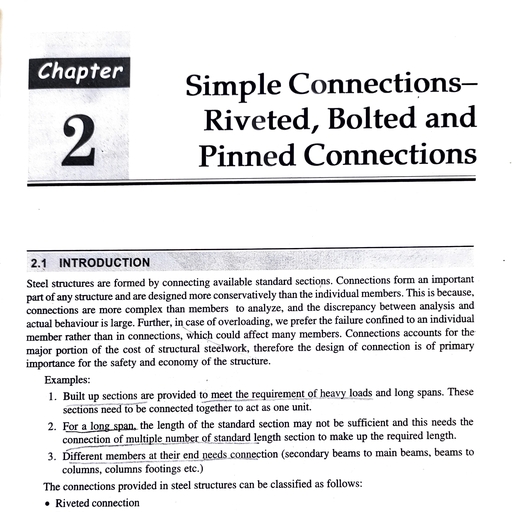
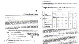
STRENGTHOFMATERIALS, , 10, , 2.11. STRESS STRAIN CURVE FOR MILD STEEL IN, , P, , E StressfA, Strain eoL, , Now,, , TENSILE TEST, , SHOWING SALIENT POINTS, , to gradually, Ifa mild steel bar of uniform cross-sectional area is subjected, Universal, testing, Amsler, in, done, increasing axial tensile force (generally is, and strain,, stress, for, the, if, we, plot graph, machine) till failure of the bar occurs, and, the following curve may be obtained:, a, , L, , PL, SL, , of, , 11, , SIMPLE STRESS AND STRAIN, , D, , Work done, , =, , Average, , force x deformation, , (i.e., distance), , -xL, Percentage elongation =x, , 100, , Example 2.1..A mild steel tie rod3m long having a cross-sectional area, 4 sq em is subjected to an axial pull of 1000 kg. If E for steel =, 2x 10° kg/cm, find (i) the stress, (ü) the strain, (ii) the, elongation of the rod,, and (iv) work done., , STRAIN, , Solution: Given, Length of the steel rod L=3 m = 300 cm, A-Propor tion al limit, , Area of the steel rod = A =4 cm*, , 8-Elastic, , limit, C-Upper yield Poin t, , Pull, P= 1000 kg, , E=2x 10°kg/cm, , C-Lower yield Point, D-Ultimute stress Point, E-Breaking Point, Fig. 2.4., , (i)Stress,f===250 kg/cm2 Ans., , A Plot of Stress Vs Strain for Mild Steel Specimen in Tensile, , Test, , The curve may be divided into following parts, , (ii) We know, Stress, , to, OA: This portion is absolutely straight, where the strain is proportional, limited, is, upto, the load, i.e., to the stress and the material obeys Hooke's law. This, 2.4. The value of stress at point A is called proportional, A as shown in, , Strain, , 250= 0.000125, Strain =Stress 2x, 10°, (it) Again,, , Fig., OA., design, the stress of the material is to be used in the range, AB: In this portion, Hooke's law is not obeyed, although the material may, still be elastic. The point B indicates the elastic limit., even without, BC : In this portion, the metal shows an appreciable strain, recoverable when the, further increase in load (i.e., stress) and the strain is not fully, point, , Ans., , limit. In, , Elongation, , StrainOriginal length, , Elongation = Strain x Original length, = 0.000125x 300 =0.0375 cm, , load is removed. The point Cis called upper yield point., Ans., , (iv) Work done = Px elongation =1000 x 0.0375, = 18.75 kg cm Ans., , at the, CC: Yielding commences in this portion and there is a drop ofload, as, termed, is, C, The, C., commences, at, point, point C immediately after yielding, lower yield point., takes place at this, CD: After yielding has taken place at C', further straining
Page 4 :
13, , STRENGTHOF MATERIALS, , 12, , SIMPLE STRESS, , Ultimate stress, , portion by increasing the load and the stress- strain curve continues to rise upto the, load D. Strain in this portion is about 100 times than that of the portion 0 to C. At, the point D, the bar begins to form a local neck. The point D is termed as ultimate, , Thus, factor of safety =Workine, , DE: In this portion, the load falling off from the maximum until fracture at, E takes place. The point E is termed as jracture or breaking point and the, corresponding stress is called breaking stress., , Table 2.1, The average value of Young's Modulus of some standard, materials are given below for future purpose, , Material, , Young's Modulus(E), kg/cm, , N/mm, , 1.., , Steel, , 2.1x 10, , 2.1 x 10, , 2., , Cast Iron, , 1.3x 10, 1.9x 10, , 1.3 x 10, , Wrought Iron, , 1.9x 10, 0.8x 10, , 5., , Timber, , 0.8x 10, 0.1 x 10, , 6., , Copper, , 1.0x 10, , 1.0 x 10, , 7., , Aluminium, , 0.7x10, , 0.7x 10, , Brass, , 0.1x10, , Note that E may also be expressed as GNim, ie, kN/mm?, , stress, , Ultimate stress, , Hence, working stress:, , tensile stress point. Ultimate stress is calculated at this point., , SILNo., , AND STRAIN, , Factor of safety, , wire of, lifted with the help of steel, the, permissteel wireif, the minimum diameter of the, length 2 metres. Find, the elongation ofsteel, to 100 x 10° N/m.Also determine, sible stress is limited, kN/nam., =, 200, E, when stressed to its permissible limit., , Example 2.2. A load of 10 kN is to be, , wire, , lifted, P= 10 kG=1x 10* N, Length of wire, L 2 m 2000 mm, tensile stress in, f= 100 x 10 N/m= 100 N/mm, , Solution: Given: Load, , to be, , =, , =, , Permissible, , wire., , E=200 kN/mm'= 2x 10° N/mm*, Let, d= diameter ofthe wire, SL= elongation of the wire., wire due to lifting of the load,, Now, tensile stress induced in the, , 1x10, , P, , 4, , But limited f=100 N/mm,, 1001 0, , 2.12. ULTIMATE STRESS, The maximum axial load that can be applied on a member without causing, its rupture or failure is called the ultimate load. Ultimate stress of the material of, , that member is defined as the ratio of this ultimate load to the initial cross-sectional, area. Mathematically,, , load, Ultimate stressTnitialUltimate, cross sectional area, 2.13. WORKING STRESS, , It is the stress which is considered as the allowable stress for design purpose., stress, During design of a member, it should be kept in mind that the actual, of, material, developed in the member must not exceed this working stress of the, its, than, the member. Generally, the working stress of a material is not greater, , elasticlimit., 2.14. FACTOR OF SAFETY, to the working stress of any material., It is ratio of ultimate stress, , lx10, , x, , 400, , 100, , d= V, , = 11.3 mmm, , Let us take d= 12 mm. Ans., , Elongation ofthe wire, ôL=, A = cross-sectional, , area, , (1x10x2000, , x12 x2x, , 10*, , of the wire =, = 0.9 mm Ans.
Page 5 :
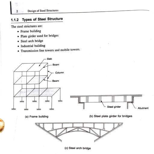
STRENGTH OF MATERIALS, , 14, , Example 2.3. A bar of5 cm dia and 400 cm long is acted upon by a, , 15, , SIMPLE STRESS AND STRAIN, , load, , of 10 tonnes. It is found to extend 10 cm. Find (a) stress, (6) strain, (c) Young's, , Elongatión ofthe portiondx=, , modulus, and (d) work done., Solution: Given,, Diameter of the bar, d= 5 cm, , Total elongation of the member due to its own weight,, , =, , 50, , mm, , E, , xinitial, , length, , Length of the bar, L = 400 cm = 4000 mm, , Load applied, P = 10 ton =1 x10° N, Extension of the bar, L = 10 cm = 100 mm, , Cross-sectional, , areaof bar,A=d=zx50? =1964 mm, , (a) Stress.f=, , 10= 50.9 N/mm Ans., , vertically, is, Example 2.4. A uniform steel wire rope 40 mtrs. long hung, self, to, due, weight, the, of, mtrs., 15, rope, from a supPport. Find elongation of top, E 2x 10 kg/cm), (weight density ofsteel wire rope 7.8 tm;, is, Solution: Given: Length of top portion of rope for which the elongation, =, , =, , (b) Strain, e OL 100, , Ans., , (b) Strain, eT4000, (c) Young's Modulus, E ==, , to, , be found out, l = 15 m, , Weight density of the material of rope, y=7.8 /m', 50.9, , =, , 7800 kg/m, , Young's modulus of the material of rope,, , 2036 N/mm Ans., , E2x 10 kg/cm° =2 x 10° kg/m, (d)Work done =xPxL=5x1x 10°x100 N-mm, , Now, we know that,, , Elongation of top 15 m of rope due to own weight,, , = 5x 10° kN-m Ans., , 2.15. DEFORMATION OFA BODY DUE TO SELF-WEIGHT, member of uniform cross-sectional area is fixed at one end with, the ceiling so that it is hanging freely under its own weight from the ceiling, as, shown in the Fig. 2.5. Let, E= Young's modulus of the material., , Aslender, A, , Cross-sectional area of the member, , y= Unit weight ofthe rod, , end, , dx, , Z2Z, , -A=yx, , Fig. 2.5., , 7.8 x 10³, , 1500, 2000, , 15.6x 10³, 19.4 x 10, 23.5 x 10, , 3000, , P=Y.A.x, . Tensile stress on the portion dr, , Ans., , 3.9x 10³, 11.7 x 10³, , 2500, , Weight of the member for a length of x,, , mm, , of diameter, Example2.5. In a tensile test on a mild steel specimen, observed:, were, 12.5 mm, following readings, Extension in em), Load (in kg), 500, 1000, , L=Length of the member, Consider now an infinitely small portion of the, member of length dx at a distance x from its top fixed, , 7800, l -81-2E, = 2x2x, 80 x152, 10t4.39x 10 m=0.0439, , 3500, , 27.3 x 10, , 4000, , 31.3 x 10, , load-extension curve, The distance between gauge points was 20 cm. Plot, and determine the value of Young's Modulus of Elasticity., Solution: Given, Diameter, , ofthe specimen, , =, , 12.5, , mm, , =, , 1.25, , cm
Page 6 :
17, , STRENGTH OF MATERIALS, , 16, , SIMPLE STRESS AND, , Area, , 1.25'= 1.22 cm2, ofcross-section ofthe specimen, A *x, , STRAIN, , =, , Cross-sectional area, , ofthe bar, A x, =, , 2', , Length ofthe specimen, L= Distance between gauge points 20 cm, , =, , 3.142, , cm, , =, , The graph of load vs extension is shown in Fig. 2.6, which is found to be a, , 2068 kg/cm, , Stressat elastic limit.f==, , straight line., , Strain at elastic limit, e =T, , 3000, , =, , 18.8 x, , 10 kg/cm, , Ans., , Yield load, , a 2500, , (il) Yield stressOriginal cross-sectional, , 2000, , 1500, , area3, , =X=2227.8 kg/cm Ans., 3.142, , 000, , Maximum load, , 0, , (iü) Ultimate stress riginal cross-sectional area, , 13x 10, 3.142, , EXTENSiON, , 6L (CM), , (iv) Percentage elongation=, , -, , Fig. 2.6., , Slope of the curve, tan, , 2068, , (i) Modulus of elasticity, E=-Strain e 0.0011, , 3500, , 500, , =0.0011, , Stressf, , 4000, , o, , 20, , 500, , 6L3.9x 10, , Now, Young's Modulus E=, , = 128205 kg/cm, , =x slope of the, , curve, , 20, , Example 2.6. A steel bar 20 mm in diameter, 20 cm long was tested to, destruction. During test, following observations, were made; Load at elastic, point 6.5 metric tonne, extension at elastic limit 0.022, cm, yield load of 7, metric tonne, maximum load 13 metric, tonne, final length 25 cm, finál, diameter 14 mm. Find:(i) Modulus, of elasticity, (iü) Yield stress, (ii) Ultimate, stress, (iv) Percentage elongation and (v), Percentage contraction of area., Solution: Given : Original diameter, of the bar =20 mm 2 cm, =, , elastic limit, P =6.5t, Elongation at elastic limit, SL = 0.022 cm, at, , 20, , (v) Percentage contraction of area, , 27X, 128205 =2.1 x 10° N/mm*Ans., 1.22, , Load, , 4138, , 100 2 5 % Ans., , x, =, , kg/cm* Ans., , T/4 (2-1.4)x 100 =51 % Ans., (T/4) x 2, , mm, of, Example 2.7. A load of 50 kN is suspended by a steel pipe 50, external diameter. If the ultimate tensile strength of steel is 500 N/mm and, , the factor of safety is 4, determine (i) the thickness of the pipe. (i) elongation, , of the pipe over a length of 200 mm if stressed to its maximum permissible, value. Take E = 200 kN/mm*., , Solution: Given: Applied load, P = 50 kN =50000 N, Factor of safety, F= 4, External diameter of the steel pipe, D = 50 mm, , Length ofthe steel pipe, L= 200 mm, Ultimate tensile strength of steel = 500, , N/mm, , Working stress for steel=lumate stress 500, F, , Let, internal diameter ofthe steel pipe =d, , N/mm?
Page 7 :
STRENGTH OF MATERIALS, , 18, , area ofthe steel pipe, A = (o-d)={ (so-#, , Tensile stress in portion BC.fA, , Young's modulus, E = 200 kN/mm, , Safestress=, , (i), , 125=, , or, , Tensile stress in portion CD.fj = A,, , Elongation of the member,, , 50000, n/4 (50-dA, , of BC+ Elongation, 8L = ELongation of AB + Elongation, , -, , or (50-d)= $00004 0 0, 50--600, , of the pipe=, , AA As, , pull P=300kN 30000N, 100000 N/mm, Young's modulus E= 100 KN/mm*=, Stresses in each section following Fig. 2.8., , 3044.62=2.69, 2, , mm, , Ans., , A(50-44.62) =399,.81 mm, 50x 200, AE, , 399.81 x 200, , A, , 30KN, =, , 0.125, , mm, , -200 mm, , Ans., , 2.16. STRESSES IN MEMBERS WITH VARYING CROSS-SECTIONS, Consider the following non-uniform cross-sections of a member, AB, BC and, CD having cross-sectional areas A1, ,Az and Az with lengths Li Lo and La, as, , 200mm, , 10mm 7, , 7/, , - 3 0 KN, , +I50mm, , Fig. 2.8, For portion AB, Length, Li, , =, , 200 mm, , Diameter, di = 30 mmn, , ,, , shown in Fig. 2.7., , Cross-sectional area, Aj =*x 30* = 706.85 mm2, Stress in, , P, , -P, , -j3, Fig. 2.7., , Tensile stress in, , 20mm, , 30 mm o7, , Let the elongation of the pipe = ôL, , L-, , =, , Solution: Given: Axial, , (ii) Required sectional area of the pipe,, , We know,, , of 30, , Take E = 100 kN/mm., , d= 44.62 mm, , Thickness, , portion AB.fi, , of CD, , diameter, 560 mm long, has a, Example 2.8. A round copper rod,, 200 mm, over a length of, 200 mm, a diameter of 20 mm, mm over a length of, in, stresses, the, Determine, and a diameter of 10 mm over its remaining length., kN., 30, of, a, rod when it is subjected to pull, each section and elongation of the, , 125, , or, , 19, , SIMPLE STRESss AND STRAINN, , Axial load, portion Ab Area of cross-section, 30000 42.44 N/mm, , 706.85, , For portion BC, Length, L2, , =, , Ans., , 200 r:, , Diameter, dh=20 mm, , Sectional area, Az = x 20?: *14.15 mm?
Page 8 :
20, , STRENGTH OF MATERIALS, 21, , SIMPLE STRESS AND STRAIN, , Stress in portion, , Axial load, , BCArea of cross-section, 30000, 314.1595.49 N/mm Ans., , Forportion CD, Length, Lg, , =, , A, , 2t, , t, , 6t-, , 150 mm, , -I-5m, , Diameter, ds = 10 mm, , Im--I:5m-, , Sectional area, Asx 10= 78.53 mm, Stress in portion CD =-, , Fig. 2.9., , Elongation of AB = ôAB =, , Axial load, , 6x 150, , AE, , Area of cross-section, , 30000, 78.53, , 0.09 cr, , x(2.5)?x 2x 10, , Part BC: This section of the rod is subjected to a tension of 6t + It = 7t., =, , 382.01 N/mm Ans., , LH.S. =6+1=7t; R.H.S. =5+2=7ttensile), , Elongation of the rod,, , Elongation of BC 8gc=, , 7x 100, , =, , AE, , x, , = 0.07 cm, , (2.5x2x 10, , Part CD: This section ofthe rod is under a tension of 5t (L.H.S. = 6+ 1-2, , 5t; R.H.S. =5ttensile), , 30000200 200, 100000, , 706.85, , 150, , 314.1578.53, , 84 mm Ans, , 2.17. PRINCTYLE OF SUPERPOSITION, In ind stries, there may be situations where a, member is, to external, axial forces not only at its ends, but also at some of its interior subjected, cross-sections along, the length of the body. In such cases, the total deformation of the, member may be, evaluated by spliting up the entire member (i.e., free, into several, body, diagram), sections and summing up the deformation of each of these sections. This, principle, of finding out the resultant deformation is, known as principle of superposition., , Elongation of CD= 8cp=3L3,, E, , 5x 150, , x, , = 0.08 cm, , (2.5x2x 10, , Total elongation ofthe rod,, L=8As +8ec+8cD= 0.09 +0.07+0.08 =0.24 cm Ans., Example 2.10. A memberABCD is subjected to loading system as shown in, , Fig. 2.10. Determine the net change ofthe length. Take E = 2x 10 N/mm., Solution:, , Portion AB: Length, Li, , =, , 1.5 m=, , 1500 mm, , Mathematically, the change in length of such member is given as:, , SL=1Li+Phla+PsLg+..., , 30 mmw30mm, , AE, , 20mm 20mm, , 25mmx25mm, , where, P1=Force acting on the section (1), Li, , =, , Length of the section (1), , P2 L2, Ps La,... are the corresponding values of section 2, 3 and so on., Example 2.9. A steel rod of 2.5 cm diameter is subjected to a force as, shown in Fig. 2.9. Find the elongation of the rod. Take E =2x 10 t/cm., , 120KN, , 220KN, , SOKN, , 10.-75m J, , Solution: Part AB : This section of the rod is under tension of 6t. (L.H.S. =, , 6t; R.H.S., , =5+2-1=6t tensile), , 150KN, , Fig. 2.10.
Page 9 :
22, , STRENGTH OF MATERIALS, 23, , SIMPLE STRESS AND STRAIN, , Sectional area, A = 30x 30 =900 mm2, Since the portion of the member is under a tensile load, R.H.S. = (220 +50)-150 = 120 kN tension], , [left side, , The bar AB is rigidly fixed between supports., =, , 120 kN, , Elongation of AB , 84B = Pi L, , 120000 x 1500, 900, , x, , 2x, , Extension of AC=a, , Imnm, , 10, , AE, , Where, A = Sectional area of bar, , Portion BC: Length, L2=1m=1000 mm, This, , 20, , E= Young's modulus, , 400 mm2, =, , =, , 120- 50=, , Contraction of CB = 2, , AE, , P2= 70 kN =7x 10 N, ., , Elongation of BC,, , R1a R2b, AE, , PzL2_7x 10°x 1000 = 0.88 mm, , SBc=A2 E, , 400 x 2 x 10, , Sectional area, As = 25 x 25 = 625 mm2, , of CD, ScD=3L322 x 10'x750 =, , A3 E, , 120+ 150, , =, , Ra, , 1.32 mm, , From (ii), , =SAB +Ogc+ocD =1 +0.88 +, , 1.32 = 3.2, , mm, , Ans., , Example 2.11. A homogeneous rod of constant cross-section is attached, to unyielding supports. It carries an axial load P, applied as shown in Fig. 2.11., , Determine the reactions R1 and R2., , R, , R1, , (, , b-, , given in the Fig. 2.12., , 3t, , 6 cm, , 8t, L40cm, , -, , Z, , 80 cm, , Fig. 2.11., , Solution: From Fig. 2.11 it is clear that, while the portion CB will be in compression, R +R2= P, , Fig. 2.12., the, , portion AC will be, , in tension,, , a+b =L), , =R2>, , 4cm, , R2, , aPP, , Example 2.12.Calculate the change in length of the rod ABCD carrying, axial loads asshownin Fig. 2.12. E =2000 tUem. The cross-sectional areas are, , A, P, , R+Ra=P, , R1-P, , or, , 625 x 2x 10, , Total elongation of the, member ABCD,, , SL, , .i), , Substituting the value of Ri in eqn (i), , This portion of the member is under a tensile load P3 (L.H.S., 220; R.H.S. =220 tension), P= 220 kN = 22x 10 N, ELongation, , AE, , Ri =Ra, , Portion CD: Length, La = 0.75 m= 750 mm, , 50, , of material., , Compressive force in CB = R2, , portion of the member is under a tensile load, P2 (L.H.S., 220 150 70 kN tension), , 70kN; R.H.S., , Extension of AC= contraction of CB., Tensile force in AC = Ri, , P 120 kN =120000 N, , Sectional area, A2 = 20 x, , ., , Solution: Portion AB: Length L=40 cm, Sectional area, Ai, , =, , 4, , cm, , 3cm2, 3t, , 30cm
Page 10 :
25, , 24, , STRENGTH OF MATERIALS, , SIMPLE, , STRESS AND STRAIN, , .2), This portion is subjected to a tensile force, P, , Ph L 3x40, Elongation of AB, dABA, E4x 2000, Portion BC:, , Length, L, , =, , 2/, , = 3t, , From eqn (1), 2+h=4.08, , 0.015 cm, , 0013 em, , 4.081.36 N/mm, , 80 cm, , Sectional area, A = 6 cm, , This, , portion is subjected to a compressive force, P2, , =, , 8t, , -, , 3t, , =, , Pz, 80, cm, Contraction of BC =OBC= AL5x, E6x2000 0.033, Length, Ls= 30cm, , This portion is subjected to a compressive force, Pa=8 -3 - 3= 2t, , 20000.01 cm, , A3E, , Example 2.13. A barAD made ofsteel placed vertically between two rigid, , supports of Aand D. The bar is loaded at B and Cas shown in Fig. 2.13. Find, the stresses in portion AB, BC and CD and displacement of B and C., , The area ofbar 70 mm x 70 mm and E for steel =2.1 x 10° N/mm., , Considering first, , Solution: (a), the effect of load 2 kN at B as shown in, Fig. 2.13 (a)., , Tensile load on AB + Compressive load on BD = 20 x 10 N, x, , Au, , 0-75m, , 0-75m, , Also, elongation of AB= shortening of BD, , x 750-x 1500, , Stress in BC, , =, , 2.72, , N/mm, , (Tensile), , 1.36 N/mm' (Compressive), , =, , 1.36, , N/mm, , (Compressive), , Next, , we, , tensile stress, , on, , A LLL, , T, 0-75m, , AC=fs, , Tensile load on AC+ Compressive, , 0-75m, , load on CD, , 30x 10 N, x, f x (70 x 70) +fa (70 70), , =, , 30000, , .(3), , +f=6.12, , Elongation of AC= shortening, , 30 KN, , C, , of CD, , Fig. 2.13 (b), , 1500-x 750, , 2s-f, Fromeqn. (3),f+2s=6.12, , fA=2fj=2 x 2.04 =4.08 N/mm, ., , For 30 kN load at C, , ol, Fig. 2.13 (a)., , 0-75m, , 0-75m, , D, , = 2 . 0 4 N/mm2, , 20 KN 0-75m 20KN 0 75 m, , 30KN 0-75m, , .1), , N/mm, , Compres_ive stress on CD =f, , T, , (70 x 70) +f2 (70 x 70), , 20,000, A+fh=4.08, , =, , x, A LLLLLLL., , 2.72, , =, , as, consider the 30 kN load at C, tension, cause, will, load, shown in Fig. 2.13 (b). This, CD., in AC and compression in, , (b), , Let,, , member ABCD,, , Total contraction in length of the, 8L 8pc+8cD -8s» =0.033 +0.01 -0.015 = 0.028 cm Ans., , This load will cause a tension in, portion AB and compression in portion, BD. Let the tensile stress in AB befi and, compressive stress in BD be f, , Stress in AB, , Stress in CD, , Sectional area, A = 3 cm 2, , Contraction of CD, öcD=A, , 1.36, , For 20 kN load at B, , =, , Portion CD:, , f 2fh 2 x, , 5t, , Stress in AB = 2.04 N/mm (Tensile), Stress in BC=2.04 N/mm (Tensile), Stress in CD= 4.08 N/mm (Compressive), Due to combining of two loads at B and C,, =, 2.72 +2.04= 4.76 N/mm (Tensile), Net stress, , at AB, , (4)
Page 11 :
STRENGTH OF MATERIALS, , 26, , 27, STRAIN, SIMPLE STRESS AND, , Net stress at BC= 2.04 -1.36 = 0.68 N/mm (Tensile), Net stress at CD = 1.36 + 4.08 5.44 N/mm (Compressive), , ey, , P, , axialEstressP-T, E, D, , mE, , -mx)E, , Displacement of point B,, = Elongation of AB due to net tensile stress in AB, , Extension ofthe elemental length dr, , 4Pdx, , =ex X dr ==, , Net stress in A5x Length of AB, , r, , E, , 4.76, 2.1x10, , 750 = 0.017, , x, , mm, , Total extension, , Ans, , (D, , ofthe bar, öL, , =F, , E, , -mu), , 4Pdr, , } n(D1-mx) E, , Similarly displacement of point C,, , Contraction of CD due to the net compressive stress in CD, , Net stress in CDx Length of AB, E, 5.44, , 2.1x10, , 0, , D1-mL, x, , 750= 0.019 mm, , Ans., , Di-mxK0, , 1, , 2.18. EXTENSION OF A SOLID CIRCULAR BAR TAPERED, , TEm, , m=-, , D1-(D1-Di), , UNIFORMLY DUE TO AN AXIAL FORCE P APPLIED AT, , 4P(D1-D2, , EACH ENND, , TEm D1 D2, , Let us consider a tapered bar as, , shown in Fig. 2.14. It is required to find, the extension of the bar subjected to a, Pat the ends., , Let, Di, section, , =, , diameter, , of the, , bigger, 4PL, , TtEDI D2, Example 2.14. A steel rod circular in section tapers, , Consider an elemental length dx at, distance of x from the wider end., , Fig. 2.14., , Diameter of the bar atx distance from the wider end,, , D=D1-D -D)=D1-m, where,, , L, , TED D2X|, , D=diameter of the smaller section, L=length ofthe bar., a, , m--D, , 4P (D-D, , pull, , D-D, , Solution: Given:, , Length of the rod, , =, , 60 cm = 600 mm., , Diameter of bigger end, Di = 2 cm = 20 mm, Diameter of smaller end, D2= 1 cm = 10 mm, , m=-, , L, , Tensile load, , Sectional area at this section, A, =, , (Di-mx), , Axial strain at this section,, , from 2 cm diameter, , will increase, to 1 em diameter in a length of 60 cm. Find how much its length, 10°N/mm, under a tensile force of 20 kN. Given, E =2x, , applied at each end, P, , =20 kN, , =, , 2, , x, , 10 N, , Young's modulus of the material of rod, E = 2x 10° N/mm, , Increase in length of the rod,
Page 12 :
STRENGTH OF MATERIALS, , 28, 4x, , 4PL, , SIMPLE, , 2x 10"x 600= 0.38 mm Ans., , OED D nx2x10° x20 x, , 10, , s00, , 500, , Example 2.15. A steel flat plate tapers uniformly from 200 ma, 100 mm width in a length of 500 mm and uniform thickness of 20 m to, Determine the elongation of the tapering plate if it is subjected to an axial m, pull, kN. Take E 2 x 10° N/mm., , of40, , 29, STRESS AND STRAIN, , &l, , (1000-), log,, d, los (1000-), (10-) 20x(-1, , 20, , log, 1000)=, 220(log.500-, , =, , (log., , 1000 -Iog.500), , log=log,2 =x0.693, , Solution: Given: Width at A = 200 mm; Width at B = 100 mm, , 20, , Thickness = 20 mm, , 0.035 mm Ans., A, , 4OKN, , 200mm, , 40KN, , 00mm, , 500 mm, Fig. 2.15., , Axial pull, P=40 kN =40 x 10 N, E=2x 10° N/mm?, us, , take an, , Let, P= total load on composite, L=length ofthe each bar, , elementary length dr at a, , distance of x from the end having, , bigger section., Width of the plate at a distance of x from A, , 200-(200-100)x, Cross-sectional area at this section,, , 200-, , Stress,, , 10x10, , ez, , ., , 1, , dx=20 (1000- x, , The total elongation of the plate,, , Fig. 2.16., , =, , Area of cross-section, , =, , Load carried, , dx, , by it, , =Young's modulus, , fi Stressinduced., For bar (2), , A2 Area of cross-section, Pa= Load carried by it, =, , Young's modulus, Stress induced., , Now the total load on, , 10x10, =, , E, , f, , (1000-x) x2x 10 20 (1000-x), , Elongation of dx, , A, , E, , f=(4000-4x) (1000-x), , Strain e,, ., , 40x 10, , bar, , For bar (1), P1, , A=20x 200-(4000-4), ., , (i) Elongation or, materials are also equal., the strains induced in those, are equal. Hence,, member, individual materials of a composite, (ii) The sum of loads carried by member., the, is equal to the total load applied on, 2.16, The composite member shown in Fig., two, of, &, (2), below is made up of two bars (1), different materials., , Length= 500 mm, Let, , COMPOSITE MEMBERS, 2.19. STRESSES IN, materials, joined, of two or more different, A composite member is composed, as a single unit., or compressed, such, a way that the system is elongated, in, together, are to be followed:, two governing principles, In such a case, the following, member, materials of a composite, contraction of individual, , composite bar,, , P=P1+ P2, The stress in bar (1),, , Loadcaried bybar (1)_, , JArea of cross-section of bar (1) A
Page 13 :
STRENGTH OF MATERIALS, 30, , 31, , SIMPLE, , STRESS AND STRAIN, , P= A, i), , Similarly, Pa=fh Az, , and P2 in equation (i),, , Substituting the value of P;, P=f A1 +fAA2, , we, , 30 x 10=1409f, , get,, , x10-21.29 kg/cm, f 30, 1409, , ..(iv), , Again, strain in bar (1),., , Stress in bar (1), , Young's modulus of bar (1), , =15 f, E1, , Load, , eE, , on, , Let the, , We know, strain in bar (1) = strain in bar (2), , Then,, OI, , From these equations stresses in each material and load carried by each, material can be easily determined., , Or, , or, , Example 2.16. A load of 30 tonnes is applied on a short concrete column, , 25 cmx 25 cm. The column is reinforced by steel bars oftotal area 56 cm'. If, the modulus of elasticity for steel is 15 times that of concrete, find the stresses, , in steel and concrete., , If, the stresses in concrete should not exceed 40 kg/cm', find the area of, steel required so that the column may support a load of 60 tonnes., , Sectional area of, , column,, , A = 25 x 25 =625 cm, , Area of reinforcement, A, = 56 cm*, , Sectional area of concrete, Ac 625 56= 569 cm*, =, , kg, , steel. f,, , =, , mxf, , the column,, , P=, , Let, stress in steel =f, Stress in concrete fe, Case (i): Here, strain in steel strain in, concrete, , =, , =, , =, , 319.35, , Ans., , kg/cm, , Ans., , 40 kg/cm, , 15 x 40, , =, , 600 kg/cm, , 60 tonnes =60 x, , 10 kg, , of steel required A,, P=fxAs +fe xAc, =, , area, , As+Ac, , 60 x 10 =600 x A, +40 x (625-As, , 560 A, = 35000, , As=, , 35000 62.5 cm Ans., 560, , internal, diameter 75 m m and, tube ofexternal, Example 2.17. A short steel, and, having, of same length, a brass tube, diameter 50 mm is surrounded by, are, tubes, rigidly, The, internal diameter 75 mm., external diameter 100 mm and, carried, load, the, Find, kN is placed on the tubes., fixed and an axial load of 20, c m long. Givens, of each tube, if it is 25, by each and also shortening, , E, =2x 10° N/mm, Solution: Area, , and E,, , Area, , =, , 1x 10° N/mm, , ofsteel tube, A,=, , ofbrasstube,Ab =, , (75-50), , =, , 2434.3, , mm, , (100-75)= 3436.1 mm, , Strain in steel tube = strain in brass tube, , 2x 10, , =, , =, , f2f, Axial load, P=fxA, +6 xA, , 20,000 2fix 2454.3 +fox 3436.1 8344.7 f, =, , hfmf=15/£, Again, the load carried, P=fsA, +fe Ac, , =625 cm, , 60 x 10=600 A, +25000 -40 A, , -, , m=15, , 15 x 21.29, , f, , Stress in, , Solution: Given: Load on column, P =30 tonnes =30 x 10°, , =, , Case (ii): Stress in concrete,, , Similarly, strain in bar (2),, , x 569, , 10=15f, x 56 +f, , 30x, , or, , 20,0002,39 N/mm, fg344.7
Page 14 :
32, , STRENGTH OF MATERIALS, S2f=2 x 2.39 = 4.78 N/mm, , kg/em*, member(3),s = ==150, kg/cm, Stress inmember (1)./ ===75, , Load carried by brass tube, , Stress in, , =fxA =2.39 x 3436.1, , =, , 8212 N Ans., , Load carried by steel tube, fxA=4.78 x 2454.3 = 1 1731.55 N, , Tubes, , Ans., , rigidly fixed at the ends so both the tubes are shortened by same, , are, , amount, , 33, STRAIN, SIMPLE STRESS AND, , Shortening of brass tube, 2 3 x 2500.0059 mm, , From the relation,fi a =fhas, or, , 75 a = 150 as, , 1 -2, , OI, , a3, , 1x 10, , a1 = 2 a3, , Shortening of steel tube, ôL, = 8Ls = 0.0059 mm, , &, , =, , XL_475* Z0=0.0059 mm, , E, , Balanced load., , Again, fi a +fs a, Substituting the value of a1,, , Check: Shortening of steel tube,, , 75, , 2x 10, , OL, , Example 2.18. Three members of different cross-section carried a load, of 8 tonnes. Stress in 3rd member is twice the 1st and one half of the 2nd. The, 2nd rod carries 30% of the total load. Find the cross-section, of each rod, if, , maximum stres that any member can withstand is 300, , kg/em., , x, , 2 as, , +, , we, , get,, , 150 x, , =, , a, , 5600, , 300 a3=5600, , 560018.67 cm, as300, a1, , =2xas =2x 18.67 = 37.34 cm, , a1=37.34 cm, a2 8, , cm2, , a3= 18.67, , cm* Ans., , diameter is placed, bar 500 mm long and 75 mm, 100 mm outside, and, diameter, inside, mm, 80, with, inside an aluminium tube, axial, bar. An, compressive, diameter. The tube is longer by 0.2 mm than the, fitted at both ends., load of 500 kN is applied through rigid cover plates, =, kN/mm*, Calculate the stresses in the bar and tube, given that E, 200, , Example 2.19. A steel, , 8 TONNES, Fig. 2.17., , olution: Given: Load carried by, three, , members, , =, , 8 tonnes, , =, , 8000 kg, , Maximum stress 300 kg/cm, Let, the stresses in member 1,2 and 3, are fi f, =, , Area, , and f respectively., , of member 1, 2 and 3 are a, a2 and az respectively., , Load carried by the member (2) 8000 x 0.3, Since in member (2), maximum stress can be, =, , =, , developed,, , Considering stress in the member (2) = 300, Sectional area of member (2), a, Balance load, , =, , 2400, , = 300, , 2400 kg, , kg/em, , =8, , cm2, , 8000-2400 5600 kg is shared by member and, (1), (3), , and EAL=75 kN/mm'., mm longer than the steel bar. So, after, mm gap between tube and bar at the, 0.2, load,, firstly, application of compressive, the, load P1, which will cause 0.2 mm, calculate, us, first, So, let, filled, is, up., top, contraction in the aluminium tube., , Solution: The aluminium tube is 0.2, , Given: Length of the steel bar, Ls= 500 mm, , Length ofthe aluminium tube, LaL (500-+0.2) 500.2 mm, Area ofthe tube, AAL=x (100-80) =2827 mm, =, , Area ofthe bar, A =~x 75= 4417 mm?, , =
Page 15 :
STRENGTHOF MATERIALS, , 34, , 35, sIMPLE STRESS AND STRAN, , Young's modulus E,, , =, , 200 kN/mm*, , 500KN, , EAL 75 kN/mm, , T, , To Calculate load Pi, , 4000 KG, , 800 mm, , Let, SL= Decrease in length of AL tube, Pi LAL, , SL=AAL X EAL, Px500.2, , or0.2=, , 2827x, , 500KN, , 75, , VERTICAL SECTION, Fig. 2.19, , Fig. 2.18., , P 2 X 2827 x=84.78 kN, , Strain in copper rod, e =E, , Strain insteelrod, e, =, , 500.2, Hence remaining load (500-84.78) = 415.22 kN will cause stresses in tube, and bar., , :, , Decrease in length, , Let, stress in the tube = fAL, Decrease in length, , Stress in the bar = fs, , ofsteel rod, , 6L1 =6,xL=xL, , of each copperrod, , Since the decrease in length of, , Then, strain in steel bar = strain in AL-tube, , =, , =, , 6l=exL=xL, , decrease in length, steel rod is equal to, , of each, , copper rod,, , EAL, Es, , xLxL, 200 AL=2.67 fAL, , 2x, , f, , xx, , Again, remaining load =f. x A, +fALX AAL, or, or, , x, , f=1.21f, , 415.22 2.67 fAL X4417+fALX 2827, 415.22, , 1.1, , 14620fAL, 415.22 0.0284 kN/mm* = 28.4 N/mm, fAL=9, , Now, load P=Load taken, , =, , by steel rod +, , 10, , 10, , 200, , 300X, , 2xload taken by each, copper rod, , 4000=fsxas+2fc Xac, , Ans., , = 1.21 fx 4.90+2x 4.90 xf = 15.74 fe, , f=2.67 x fAL =2.67 x 28.4 = 75.83 N/mm* Ans., , Example 2.20. Two copper rods and one steel rod each of 2.5 cm diameter, together support a load of 4000 kg as shown in Fig. 2.19. Find the stresses in each, rod. Take E for steel and copper as 2x, 10° kg/cm and 1.1x 10 kg/cm*, , respectively., , Solution: Area of the steel rod, a,, , =x2.5, , =, , 4.90, , cm, , Area of the each copper rod, a = 4.90, cm, Let, stress in the steel rod =f: Stress in the copper rod, , =fe, , f=121f, , 4000 254.13 kg/cm, f5.74, Ans, 1.21fe=121 * 254.13 =307.49 kg/cm*, steel and copper are rigidly fixed, Example 2.21. Two vertical rods of, m long and, cm apart. Each rod is 3, with the ceiling at their upper end at 100, ends, lower, of the rods., cross piece connects the, 25 mm diameter. A horizontal, it remains, that, so, on the cross piece, Where should a load of 3.5 tonnes be placed, E for, and, steel =2x 10° kg/cm*, horizontal after being loaded. Take E for, and, , copper, , f, , 1.0 x, , 10° kg/cm.
Page 16 :
STRENGTH OF MATERIA, Solution: Letf, andfebe the axial stresses, , induced in the steel and the cin, , 37, SIMPLE STRESS AND STRAIN, , copper, , ds respectively, , Load carricd by copper, P=fx A,, , rod, , =237.7xx(25)=1167, , -100 cm3m, , Steelrod-, , Ps, , Copper, rod, , 3.5 Ton, , 35, , Ton, , Taking moment about A (See, , X, , B, , 100cm, (b), , (a), Fip. 2.20., , The strains in the both materials, , feE, , Let Ps and Pe, , are, , 1.167 ton, , Fig. 2.20 b),, , are same., , or, , 1.167x100=3.5 (100-x), , or, , 116.7 350 -3.5x, , or, , x= 66.7 cm, , centre line of, cm from the, distance, The load should be placed at a, the copper rod. Ans., a beam as, diameter 2 cm each, support, Example 2.22. Three rods of, rod, left, the, to remain, load Pbe placed from, shown in Fig. 2.21. Where should a, =2x10° kg/cm,, beam., the, weight, the beam horizontal? Neglect, , of 66.7, , ofthe, , or, , =, , Pex 100 3.5 x (100-), , Cross piece, A, , the, , kg, , Take E,, , E= 1x10 kg/cm*,E, =6x10°kg/cm, , 2x 10, lx10 2, , the loads carried by the steel and the copper rods respec., , 4m., , 4m, , tively., Ps+ Pe= 3.5 ton = 3500 kg, , But,, , P,=fxA, and Pe=fcxAc, , where, A, and A, , are, , the cross-sectional, , areas, , of the steel and the copper rods, , respecively., Ps+P=fA,+feA¢ Ac =3500, or, , X, , xx25+fxäx(25=3500, 4, 713, JaTJe 3500, 71, 3, x4 (2.5, , Solution: Sectional area of each rod, Let the load shared, , by steel,, , =, , =, , (Or, , 237.7, , brass and aluminium be Ps, Pb, , and Pa and, , brass and, Since the rigid beam remains horizontal, the extension of seel,, can say,, we, them, are, of, all, of, equal,, aluminium are equal. As the length, Strain in steel strain in brass strain in aluminium, , 2+f=71, 3fe 713, 713, , cm?, , stresses befs fo and fa respectively., , Substituting the value of f. from (i), , OF, , Fig.2.21., , ky/cm (tensile), , Ps, , Ph, , P
Page 17 :
39, , STRENGTH OF MATERIALs, , 38, , P, , x 10, oxP=2P, , XPh=, xPh =x, , Pa, , STRAIN, SiMPLE STRESS AND, , 30, 5m, -, , xP=6P, , the centre line of the steel rod., Let the load P act at a distance x tn from, the steel rod,, Now, taking moment about the centre of, Pxx=P^x 400+ Pax 800, , But,, , 40 KN, , Fig. 2.23, , P=Ps+ P + Pa, (P+P+Pa) x, , =, , 400 Ps+800 Pa, , ,, , Due to symmetry P1 = P, , Substituting the values of P, and Pa we get,, , V=0, , (2 P+, , P+6 P>) x=400 P +, , or, , ., , 800 x6 Pp, or, , Of, , mm, , =5000, Length of vertical, BD be Pi Pz and P3 respectively., and, CD, Let the forces in AD,, rod =5m, , O P)x=5200 P, , Let the, , perpendicular, , I=, x 5200, 9PbP577.77 cm Ans., , Pi cos 60° + P2+Ps, , 2 Pi cos 60°+P2=40, , 60°, , =, , 40, , P=P), , 1), , AD and let DA' be, load at D be D'. Join,, AD=AA', drawn from D on AD; then, new, , a, , position of, , A'D'= Extension, , Example 2.23. Three steel rods of diameter 10 mm support a load of, 40 kN as shown in Fig, 2.22. Determine the force in each rod and vertical, , C, , cos, , of the rod AD., , DD'= Extension of rod CD, D, From geometry, DD'=AD, , (LADD=2ADC=60), , cos 60, , displacement of the load. Take E, = 2.1 x 10 N/mm'., Extension, , Extension of rod AD(A'D, , ofrod CD,, , cos 60, , Pax length of CD_PX length of AD, 30, , *T, , Or, , 5m, , A.E, , Pax5, A.E, , 40 KN, or, , Fig. 2.22., , Solution: Area of each rod =, , x, , 10f, , =, , A. Ecos 60°, , PX-, , 5, , cos 60, , AE. cos 60, , Pa=P1 cos 60° =4 P, , Substituting the value of Pa in eqn. (1), we get,, 78.5 mm, , 2)
Page 18 :
40, , SIRENGTH OF MATERIALS, 41, SIMPLE STRESS AND SRAIN, , 2 Pi cos 60° +4 P = 40, , But, tcnsion in rope AB +, , P1+4 Pi 40, , or, , 8 kN Ans., , P3, , P=8 kN Ans., , P2=4 Pi, , +hA, , A, , P1, , =4x8, , 32, , where, A, , kN =32 x, , 10 kN, , =, , 10000 N, , cross-sectional area, , =, , fi+h=A, , Vertical displacement of load P,, , Now, , DD=L0ad on CD xLength of CDD, Ans., , h=, , 78.5 x 2.1 x 10, , downward movement of the weight. Given, cross-section area of the rope is, 500 mm and E = 2x 10° N/mm., , Putting this, , value, , 500, , from (1),, , 3, , =, , 12 N/mm Ans., , offi in (1),, , f=x 12=8 N/mm*, Also, downward, , movement, , of the, , elongation, L44L, , 2m, , weight, , of rope AB (or CD), , 2x 10, , (b) The pulley of Fig. 2.25 is, , C, , 4m, , Ans., , L_8x, 8x60000.24 mm Ans., , A, , 2m, , C, , 500 mm, , fh+h20, , Example 2.24. A weight of 10 kN is suspended by ropes as shown in, Fig. 2.24 and 2.25. In each of the cases, find the stresses in the ropes and, , A, , =, , of each rope, , substituting the value offi, , AxE, , T, , Afplicd load, , =, , 10000 10000 =20, , 10' N Ans., , 32 x 10x5000 = 9.70 mm, , =, , CD, tension in rope, , smooth. So, the tension Pis uniform throughout, , the rope., For equilibrium of the pulley,, , 4m, , Tension in, or, , portion AB +Tension in portion BC= Applied, , P+P, , load, , 10 kN= 10000N, , P10000=, 5000 N, P, 2, , 10KN, , 10 KN, , Fig. 2.24., , Stress induced in the entire rope,, , Fig. 2.25., , Solution: (a) The loads taken by the two ropes in Fig. 2.24 should be such, that they exte.id by the same amount. So, by consideringfi and h as the stresses in, ropes AB ad CD respectively,, , Extension, , l_hla, where, , L, , =, , the the entire rope, 8z, , Now, let 8 be the downward, , and La are lengths of the ropes AB and CD respectively., E, , Again, total length ofthe rope, L, , P, , f=*=, , 4+4+2, , E, , movement, , 8.(1), , 0.25 mm, , =, , 10 m, , 2x, , of the, , 2 8 Extension of whole load = ôL, , E, , =, , 10, , 10 N/mm* Ans., , =, , 10000, , 0.5, , applied load, , mm, , mm
Page 19 :
STRENGTH OF MATERIAl, , s, , AB is hinged at C' and connected with, Example 2.25. A rigid bar, as shown in Fig. 2.26, Roe, rod and a copper rod at A and B respectively,, the, at, upper ends. A load of 40 Le, rods are rigidly fixed with the ceiling, in the steel rod and the., applied at B. Find the magnitude ofstresses, , 43, SIMPLE STRESS AND SRAIN, , ., , rod. Areas ofcross-section ofsteel and copper rods are 400 mm and 600opper, n, 110, kN/mm., and, kN/mm°, E,, Take E, 200, , Px 4+Px2-40x2, 4 P+ 2 Pe= 80, , of, , =, , =, , respectively., , Taking moment about C, , =0, , .(1), , 2 P+ Pe= 40, , steel rod and the, and the tension in the, Let os and ôp are the compression, 2.27., rod respectively, as shown in Fig., , coppcr, , Steel, , -Copper, , Im, , From geometry,, or, , B, , -4m-, , 2, , 2), , SA =2 ô8, , But we know that,, , PsxL, , 2m, 40 KN, , PexL, , osAXEe, , Fig. 2.26., Solution: Cross-sectional area ofsteel rod, As = 400 mm, , Substituting the value of ô4 and os in equation (2),, , Cross-sectional area of copper rod, A, = 600 mm?, , Applied loadP=40 kN, , A,xE,*AXE, , Length of each rod, L = 1 m, Let P= Aial load induced in the steel rod, , or, , Ps, Pe, 400x 200 4 X600x 110, , Pe=Axial load induced in the copper rod, , Re=Vertical reaction at C., , P, , 5.84 P-40, , P= 40 6.85 kN, 5.84, , Substituting the above value of Pe in equation (3),, , Ps, , P, , 68, , 2.42 x 6.85 = 16.58 kN, , Stress in the steel rod,f =, , 2m, , oKN, , (3), , 2x(2.42 P) + Pe= 40, , or, , _4m, , 2.42 P, , Substituting the value of Ps in equation (1),, , or, , m, , 400x200, , PPe600x 110, , or, , Since the bar AB is perfectly, rigid, it will remain straight after the application, of extenal load P. Also, due to the, presence of hing at C, the bar will rotate about, Cin the clockwise direction, as shown in, Fig. 2.27. Thus, the steel rod will be in, compression and the copper rod will be in tension. The free body, diagram of the, bar AB is shown in, Fig. 2.28., , Rc, , Fig. 2.27, Fig. 2.28., , 40 KN, , 0.04 kN/mm, , 40 N/mm (Compressive) Ans.
Page 20 :
STRENGTH OF MATERIAL, , 44, , 45, s, , SIMPLE STRESS AND, , SRAIN, , P6.85 0.01 kN/mm, , Stressin the copper rod.fe A, 2.20. STRESS IN NUTS, , KINI, , 600, , Stress in the tube, f, , = 10 N/mm (Tensile) Ans., , bolts are tightened by placing wash, assembly of nuts and, turned but when the distance het, be, easily, nuts, may, between nuts and bolts, the, the bolts are subicectod, to the length of the bolt,, two washers are exactly equal, and, body of nuts are subiectod, further. Then the washers, ed, Whenever an, , tension, if nut is tightened, to compression., diameter passes through a steel tuho, Example 2.26. A steel rod 30 mmexternal diameter. The tube is 500 m, m, and 50 mm, of35 mm internal diameternuts, as shown in Fig. 2.29., washers, and, long and was fastened by, load of 1 kN on the, a, The nuts are tightened so as to exert compressive, the stress when the, also, Find, and the rod., tube. Calculate the stress in the tube, draw, the, piece together. Take, turn to, nut is further tightened by 1/4, =, mm., bolt thread 3, , E, , =2x, , 10° N/mm, , and pitch of the, Tube., , (Compressive), , 1001.3, , I4 turn:, , Case (i) When nut, , AND BOLTS, , 1000=0,99 N/mm, , =, , is further tightened byin the rod and compressive stress, , stress is induced, In this case also, tensile, is induced in the tube., to further tightening, Tensile stress in the rod due, Let, , fi=, , and, , fi= Compressive, , stress in the tube, , Here also, total tensile force, , xA, , on, , =xAz, , the rod, , =, , Total compressive, , force, , on, , the tube., , or, , f=141f, Decrease, , in, , length of the tube due tof, mm, , 2x 10, and increase in length of the rod due tofi, , x 500 mm, =xL=, E, 2x10, , Rod, , (" f=1416), , Since axial advancement ofnut, =, , Fig. 2.29., Solution: Given: Diameter ofsteel rod, = 30 mm, , i x 500, 1.41f'x 500o, , 4x2x10, , Sectional area ofthe steel rod A =x 30* = 706.8 mm, of, Sectional areaoftubeAz=, , 2x 10 x, , (S0-35) = 1001.3 mms, , Compressive load P= 1 kN = 1000 N, , Required net stress in the steel tube, , f+=0:99 +124.48 125.47 N/mm' (Compressive), and net stress in the steel rod,, , Then, compressive force on the tube = Tensile force in the bolt= 1000, , fA =fhA2= 100, 1000, , orStress in the rod, fi=01,41 N/mm (Tensile), , 1205, , i'= 1.41 x 124.48 = 175.51 N/mm (Tensile), , Case (i):On tightening the nut, compressive stress is induced in the tube and, consequently tensile stress is induced in the bolt., , 2x, 10, , N/mm (Compressive), = 150000124.48, 1205, , Length of the tube L = 500 mm, , E,=2x 10 N/mm2, , the rod, contraction of the tube + extension of, , =fi+f= 141 + 175.51 = 176.92 N/mm (Tens.e), 2.21. SHEAR STRESS AND STRAIN, (a) Shear Stress, , When equal and opposite forces act tangentially on any cross- sectional plane
Page 21 :
9, , STRENGTH OF MATIRIAL, , 48, , SIMPLE STRESS AND SRAIN, , f= Stress on the body, , where, , Force exerted by the punch =f Xx, , P= Force on the body, , Force required to shear =fx (Tdx), , A Area ofcross-section, , We know, f.xxd =f,xrdxi, , Strain, e -, , (s=2/), , 25x-fx, , or, , o,= deformation in lengh, , L Original length., ., of a M.S. plate in 4000, , kg/c, Example 2.29. The ultimate shear stress, it withou, through, can, that, punched, hole, a, be, Determine the diameter of, in the punch, the thickness of, exceeding a compressive stress of 8000 kg/cm, , 3., , the plate being 1.25 cm., Solution: Given :, Ultimate shear stress of M.S. plate = 4000 kg/cms, , 4., , Allowable compressive stress = 8000 kg/cm, , 5., , Thickness of the plate f = 1.25 cm, , Let diameter of the hole =d, , that the, , When a, , load, within which the, There is an optimum value of stress due to external, of stress. The optimum, strain induced in the body disappears on removal, material., the, of, limit, elastic, as, termed, valuc of stress is, , within its elastic limit,, Hooke's law states, "whenever a material is loaded, is proportional to the, material, the developed stress at any point within the, corresponding strain"., , Maximum force required to be applicd for punching the hole, , Ultimate shear stress x arca of plate to be shearcd, , 6., , of elasticity of a material may be defined, unit axial strain within the elastic limit., due, to, produced, , The Young's modulus, as the axial stress, , 4000 x Tt dt kg, , or modulus, , foce, , But the maximum compressive force that can be applicd, , Allowable compressive stress x, , area, , of punch, , =8000x, , where,f=Stress; e =Strain, Young's modulus or modulus of elasticity., Defomation of a uniform section,, E=, , 8000xd= 4000 xndt, or, , 8000xd=4000 Td125, , 8., , Deformation of a uniformly tapering body, , From which, d 2.5 cm Ans., =, , 4PL, , dLTd daE, , SUMMARY, , When an external force is, applied on a body, deforination occurs in the body, The resistance to deformation, per unit area of the, the ratio of deformation to, body is called stress and, the original, length is called urain., Su., , body, , and opposite pulls, body is subjected to two equal, and, the, in, body is called tensile stress, tends to elongate, the stress induced, corresponding strain is called tensile strain., so that the body, When a body is subjected to two equal and opposite pushes,, stress and, tends to be shortened, the stress in the body is called compressive, coresponding strain is called compressive strain., so, , d - 2 Ans, , where, di = Dia of smaller section ; d2= Dia of bigger section., , 9., , Stresses in composite section, , (i), , Pi=P, , fiA=fh Az
Page 22 :
STRENGTHOF MATERIAt, , 51, SIMPLE STRESS AND SRAIN, , rod of same length and material, a, A solid round bar is replaced by taper, TO m respectively. The, rod are 20 mm. and, Diameter and length ofthe solid, other side diameter of the, rod is 20 mm. find the, one end's diameter of taper, bar., rod be half of the round, rod if the elongation of the taper, (Ans. 40 mm), , (), , h, , and Pz are forces in material 1 and 2., and are stresses in material 1 and 2., , A, , and 2., and A are areas of cross-section of material I, , E, , and Ez are, , where,, , P, , taper, , f, , 5., , Young's modulus of matenal 1 and 2., QUESTIONS, , 1., , tube of external and, steel bolt passes through a copper, A, the stress in bolt and tube., mm. Calculate, internal diameter of 50 mm and 45, force 10 kN on the, an compressive, if the bolt is tightened by a nut to exert, 0, , mm diameter, , tube. Take, , What do you mean by stress and strain ? Derive a relation between stress and, , strain., , 6., , 2, , Define different types of stress and strain., , 3., , State Hooke's Law., , 4., , State Elastic limit., , 5., , What do you mean by principle of superposition ?, , 6., , Derive a formula for the stresses in uniformly tapering bars., , 7., , How do you calculate the stress in nuts and bolts ?, , E, =2x 10° N/mm, E, (Ans. pe, , 1.I x, , =, , 26.80 N/mm* :p, , =, , 14.14 N/mm), , reinforcement, mm reinforced by four, A reinforced column 250 mm x 250, be 70 N/mm, find the axial, bars of 25 mm diameter. If the stress in concrete, , by the column. Take m I13., to a, A steel bar shown in Fig. 2.34 is subjected, , 20KN, , (Ans. 6024.33 kN), , =, , load camied, , 7., , 10° N/mm, , =, , 20mm, , 0 mm, , tensile load of 20 kN., , 30mm, , 20 KN, , EXERCISES, 1., , -200 mm -150 mm--200 mm-, , Calculate the usual test constants from following resultsofa stecl tensile test, Dia of the specimen = 2 cm, , Fig 2.34., , Determine the change in length of bars if E = 2 x 10° N/mm, (Ans. 0.11 mm contraction), , Distance between gauge point = 16 cm, Load at yield point = 700 kg, , Maximum load during test = 1200 kg, Gauge length (after fracture) = 19.2 cm, , 8, , A steel bar is loaded as shown in, , Fig. 2.35. Find the change in length of the, , bar., , Diameter at fracture = 1.42 cm, , (Ans. Yield point stress 222.92 kg/cm*; Ultimate stress 382.16 kg/cm, =, , (Ans. 1.01 mm), , Take E= 200 GN/m., , %Elongation at fracture = 20%: % Contraction in area = 49.68%), , 2, 3., , A circu.ar rod 2 m long and 1.5 cm diameter is, Find the elongation of the rod if E = 2x 10'N, , Find the elongation of the bars, , subjected to a load 30 kN, (Ans. 1.69 mm), , showing in Fig. 2.33 under a tensile load of, , 30 kN. Take E =2 x 10° N/mm*, , (Ans. 0.82 mm), , 30mm, , 8OHN, , 20mm, 400 mm, , 40KN, 40mm, , 60KN, , 600mm., , 8 0 KN, , 500mm, , Fig. 2.35., , 0 mm, 30KN, , -30 N, , The ultimate shear stress of a mild steel plate of 10 mm is 350 N/mm., Calculate the diameter of the hole that can be punched to it without exceeding, a compressive stress of 700 N/mm*., , -300 mm, , 20 mm, , 300mm, Fig 233, , 300 mm-, , (Ans. 20 mm)
Page 23 :
STRENGTH OF MATERIAIS, , 52, , 53, SIMPL.E STRESS AND, , 0., , a load, 20 kN as shown in, Two copper rods and a steel rod supports, mm and 20 mm,, 15, are, rod and copper rod, ke, 2.36. The diameters, and 1.00x 10' N/mm'respectis, E for steel and copper 2.1 x 10°, , of, , Ta, , of steel, , ly., , by, , 2.1, , x, , 10° N/mm, E= 1x, , 5, , i5, , m, , 9i, Fig. 2.39., at the sam., rods shown in Fig. 2.40 are inuially, The free ends of the vertical, rod 3.5 i*, if, horizonial,, bar with respect to, level. Find the inclination of the, 0.009 m/cm wiis, cm/cm and rod 7.5 1n length, length is strained 0.002, , (Ans. 34 39'), , 20 KN, , supporting the load., Fig. 2.36., , A bar of uniform cross-section of 400 mm, 2.5 m length is suspended, total elongation of the, vertically and loaded as shown in Fig. 2.37. Find the, , (Ans. 0.832 mm), , bar if E 2.1 x 10° N/mm, , Two copper rods and a brass rod supports a load of 35 kN as shown in, Fig. 2.38. The diameter of copper and brass rod be 25 mm. Find the, , T, T, 3.5m A, , 6m, , stresses in rods. Take E= 1.1x 10° N/mm', E,=1.0x10 N/mm, , Fig. 2.40., Im, , 5kn, , Ckn, , O5m, Im, , 35 KN, Zm, , 3m, , 20KN, Fig. 2.37., 13., , A rigid beam, g bronze rod, , Fig. 2.38., , ABC of length 6 m hinged atA and supported by a steel rod and, , of same length. The beam also carried a load of 9 kN at a distance, 5 om from A. The steel and bronze rods are situated at a, distance 3 m and, m from A. The areas of steel and, bronze rod are 50 mm and 80 mm, , respectively., , Nimm, , Bronz L, , Copper, 20 mm, , Steel, , 14., , 12., , developed, , 3m, , Steel-, , 11., , stress, , N/mm: Ph= 7O.59, , each rod., (Ans. Pe = 6286.33 N; P; = 7425.5 N, , 3m, , Copper, 20mm, , 10° N/mm. Find the, , (Ans. P= 74.09, , in the each rod., , ive, , N/mm, , Find the load camied, , Take E,, , =, , SRAIN
 Learn better on this topic