Page 1 :
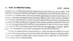
Manufacturing Process-1, CASTING PROCESS, Concept of manufacturing process:, In today's living world, we make use of various products like safety pins, tooth, brush, screw-driver, pen, cell phones, computers, fan, refrigerators, air conditioners,, automobiles etc., which are the result of manufacturing. Many of us are not aware how, these products are made, and what materials are used for making these products. But their, use has made our life easy and also changed the standard of living in the society., Manufacturing is the conversion of raw materials into usable products. The word, manufacture derives from two Latin words: 'manu', meaning ‘by hand’ and 'factum',, meaning ‘made’- almost literally hand making. In early civilizations, products like, ceramic and earthen pots were indeed handmade. Since that time, people have been, developing new ways and better techniques for producing products to meet human needs, and wants., During the final decades of 18th century, the first industrial revolution began, which led, to more technological innovations in manufacturing. Human labours were replaced by, machines. These machines enabled one person to accomplish tasks that had previously, required many workers. Further, advancement in science and technology brought, revolutionary changes in manufacturing. The dawn ofthe computer age made, manufacturing more easy, with computers controlling industrial machinery and processes., Although today many industries are being automated, the customer's demand for products, with particular feature or quality (say baskets, hand loom sarees, pots etc.,) has made the, elements of craft age to still remain in practice. But whatever may be, 'modern, manufacturing', as what we call today, continues to evolve., Importance of manufacturing process:, To live well, a nation must produce well'. The standard of living in a society is, determined by the goods and services available to its people. Throughout history, a, nation's wealth, standard of living and status in the international community have directly, benefited from the nations manufacturing capability. Transportation systems, energy, generation and distribution; construction, education, agriculture, healthcare and virtually, every aspect ofthe modern way oflife depend on the quality and affordability of, manufactured products., Manufacturing is a very broad activity encompassing many functions, from, purchasing raw material to quality control. As mentioned before, manufacturing is the, conversion of raw materials into usable products. Today, a wide range of processes and, materials, from metal to plastic to ceramics and composites are available for making, products. But, not all processes and materials are suitable. It is the engineers' ingenuity to, identity a suitable material and process, so that a productwith desired quality, optimum, performance and lowest cost can be produced., , Department of Mechanical Engineering, SUCET, Mukka, Mangaluru., , Page 1
Page 2 :
Manufacturing Process-1, Hence, a detailed understanding of various materials and processes required, their, advantages and limitations becomes essential for a mechanical engineer that helps him to, optimize the design/manufacturing of any product., Classification of manufacturing process:, , Department of Mechanical Engineering, SUCET, Mukka, Mangaluru., , Page 2
Page 3 :
Manufacturing Process-1, Classification of manufacturing process:, The various processes available for manufacturing a product can be put into, anyone of the four categories mentioned below:, (i) Casting, (ii) Forming, (iii) Machining and, (iv) Joining., (i) Casting:, Casting is a manufacturing process which involves pouring molten metal (ferrous, ornon-ferrous) into a mould cavity whose shape resembles the shape of the desired, product, and allowing the molten metal to solidity in the cavity. The solidified part is then, taken out of the mould cavity to finish the final product., Note: The process is similar to that of making ice cubes in a refrigerator, wherein water is, poured into a cavity (ice tray) and allowed to freeze. Whereas in casting process, the, molten metal is allowed to solidity in the cavity., Casting is further classified into two categories based on the type of mould:, (a) Expendable mould casting:, In this type, the mould prepared from sand, plaster or similar materials is temporary, and, is destroyed in order to remove the solidified part. In other words, a new mould has to be, prepared for each new casting. Example Green sand moulds, dry sand moulds, shell, moulds, plaster moulds, investment casting etc., (b) Permanent mould casting:, In this type, the mould fabricated out of a ductile material (example steel) is permanent, and can be used repeatedly to produce many castings. Example "die casting, continuous, casting, centrifugal casting process etc., (ii) Forming:, Forming or metal working is the process in which the desired shape and size of the, component is obtained through the plastic deformation of the work piece metal. Forming, processes are broadly classified into two categories based on the working temperature., (a) Hot working process:, In these processes, deformation of metal takes place above its recrystallization, temperature. Example: Forging, hot rolling, extrusion etc., (b) Cold working process:, In these processes, deformation of metal takes place below its recrystallization, temperature. Example; Bending, drawing, shearing etc., , Department of Mechanical Engineering, SUCET, Mukka, Mangaluru., , Page 3
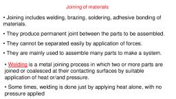
Page 4 :
Manufacturing Process-1, (iii) Machining:, Machining processes involve removing excess material from the work piece to obtain the, desired shape and size. Machining is further classified into two categories based on the, type of tool used:, (a) Traditional or Conventional machining:, These processes make use of a cutting tool to remove excess material from the work, piece. Both the work piece and the cutting tool are rigidly mounted on the machine using, suitable devices. Example, Turning, milling, drilling, grinding etc., (b) Non-Traditional or Non-conventional machining:, These processes use lasers, electron beam, chemical erosion, electric discharge and, electrochemical energy instead of the traditional cutting tool to remove excess material, from the work piece. Example, Laser beam machining, electrochemical machining,, ultrasonic machining etc., (iv) Joining:, Joining processes involve assembling or joining two or more parts together to, form a single component of the desired shape and size. They are further classified into, two categories based on the type of joint obtained:, (a) Temporary joining process:, In these processes, the joint obtained is temporary the assembled parts can be separated, easily without damage to them. Example; Bolt and nut, soldering, brazing, adhesive, bonding etc., (b) Permanent joining process:, In these processes, the joint obtained will be such that, the connected parts have to be, broken in order to separate them. Example; Welding and riveting., Selection of a Process for Production:, There are various processes available for manufacturing a product. A proper, choice has to be made, so that a product with specific requirements can be manufactured, in less time, and with minimum waste of energy and material. Following are a few factors, to be considered before selecting a process for production:, (a) Shape and size to be produced, For products with simple shape, machining is best suited. But for complex and intricate, shapes, casting is preferred. The size of the product is also an important factor. For, example, long products such as rails, or thin products such as car-body panels can be best, made by forming process compared to others., (b) Quantity to be produced, Both machining and casting can be used for producing large quantity products, but are not, suitable for small quantity products, as they are not economical., , Department of Mechanical Engineering, SUCET, Mukka, Mangaluru., , Page 4
Page 5 :
Manufacturing Process-1, (c) Type of material, Materials possess various properties like ductility, hardness, toughness, brittleness etc., Hard materials cannot be machined easily. Brittle materials cannot be mechanically, worked (Forming process). In such cases, casting is preferred., (d) Surface finish and dimensional accuracy, Casting with expendable moulds does not yield good surface finish. However, if casting, process is selected, it should be followed by machining process to obtain the desired, surface finish and dimensional tolerance., Casting with permanent moulds like die casting process yields good results. But when, surface finish and dimensional tolerance is a major factor, one can choose non-traditional, machining process., (e) Quality and property requirements, A defect-free product with specific properties serve its purpose for long life. Properties of, cast materials are generally less when compared to those of mechanically worked, materials. Also, casting gives a lot of defects. Hence, a process that gives better properties, and quality should be selected., (f) Cost of the product, Customers often demand for products with more features and performance at reduced, prices. Hence, a low cost production process should be selected, but at the same time, see, that no compromise is made in terms of quality., , Introduction to casting process, Casting or Founding is one of the oldest manufacturing process that has been, practiced for over 5000 years. Pre-historic man found copper and shaped it to use as a, weapon (arrowhead) for his defence. Later he found that weapons could be easily made, by melting and pouring copper in moulds (cast) than they could be beaten (forged) to size, and shape. Progress in civilization made man to discover different metals and process for, casting them. Casting involves melting metal and pouring it into a mould cavity whose, shape resembles the shape of the desired object, and then allowing the molten metal to, solidify in the cavity. The solidified part is taken out of the mould, cleaned and finished to, make it suitable for use. Casting is not restricted to metals. Glass and plastics can also be, cast using a variety of processes. Also, products ranging from a few millimetres to meters, and a few grams to several tons can be cast efficiently and economically thereby making, it a versatile method for shaping objects. Casting which was once practiced as an art has, emerged to a science, and a major manufacturing process to shape objects., Steps involved in making a casting:, The basic steps in making a casting include:, (a) Pattern making, (b) Mould preparation (including gating and risering), (c) Core making, (d) Melting and Pouring, (e) Cleaning and Inspection, Department of Mechanical Engineering, SUCET, Mukka, Mangaluru., , Page 5
Page 6 :
Manufacturing Process-1, (a) Pattern making, A pattern is a replica of an object to be cast. It is used to prepare a cavity into which the, molten metal is poured. A skilledpattern maker prepares the pattern using wood, metal,, plastic or other materials with the help of machines and special tools. Many factors viz.,, durability, allowance for shrinkage and machining etc., are considered while making a, pattern., b) Mould preparation, Mould preparation involves forming a cavity by packing sand around a pattern enclosed, in a supporting metallic frame called flask (mould box). When the pattern is removed, from the mould, an exact shaped cavity remains into which the molten metal is poured., Gating and risering are provided at suitable locations in the mould., c) Core making, In some cases, a hole or cavity is required in the casting. This is obtained by placing a, core in the mould cavity. The shape ofthe core corresponds to the shape of the hole, required. The mould is cleaned, finished and made ready for pouring molten metal., d) Melting and Pouring, Metals or alloys of the required composition are melted in a furnace and then transferred, (poured) into the mould cavity. Many factors viz., temperature of molten metal, pouring, time, turbulence etc., should be considered while melting and pouring., e) Cleaning and Inspection, After the molten metal has solidified and cooled, the rough casting is removed from the, mould, cleaned and dressed (removing cores, adhered sand particles, gating and risering, systems, fins, blisters etc., from the casting surface) and then sent for inspection to check, for dimensions or any defects like blow holes, cracks etc., , Department of Mechanical Engineering, SUCET, Mukka, Mangaluru., , Page 6
Page 7 :
Manufacturing Process-1, , Figure 1.1: Steps involved in making a casting, Procedure for Making a Casting, To understand and appreciate casting process, a detailed step-by-step procedure is shown, in figure 1.2., , Department of Mechanical Engineering, SUCET, Mukka, Mangaluru., , Page 7
Page 11 :
Manufacturing Process-1, Terms Involved in Casting:, Figure 1.3 shows the cross-section of the mould ready for pouring., , Following are a few important terms involved in casting process., a) Mould box (flask) : It is usually a metallic frame used for making and holding a sand, mould. The mould box has two parts: the upper part called cope, and the lower part called, drag., b) Parting line/parting surface: It is the zone of separation between cope and drag, portions ofthe mould in sand casting., c) Sprue: It is a vertical passage through which the molten metal will enter the gate, and, then into the mould cavity., d) Pouring basin: The enlarged portion ofthe sprue at its top into which the molten metal, is poured., e) Gate/ingate: It is a short passageway which carries the molten metal from the runner/, sprue into the mould cavity., h) Riser: A riser or feedhead is a vertical passage that stores the molten metal and, supplies (feed) the same to the casting as it solidifies., i) Mould cavity: The space in a mould that is filled with molten metal to form the casting, upon solidification., j) Core: A core is a pre- formed (shaped) mass of sand placed in the mould cavity to form, hollow cavities in castings., k) Core print: It is a projection attached to the pattern to help for support and correct, location of core in the mould cavity., i) Ladle: It is usually made from graphite or silicon carbide, and is used to hold molten, metal during pouring., Department of Mechanical Engineering, SUCET, Mukka, Mangaluru., , Page 11
Page 12 :
Manufacturing Process-1, Components produced by casting process:, Casting is the first step and the primary process for shaping any material. All, materials have to be cast before it is put to use. The ingots produced by casting process, are used as raw material for secondary processes like machining, forging, rolling etc., More than 90 % of all manufacturedgoods and capital equipment use castings for their, manufacture. To list the components produced by casting is an endless process. A few, major components produced by casting are given below., • Automotive sector - Nearly 90 % of the parts in automobiles are manufactured by, castings. A few parts include brake drum, cylinder, cylinder linings, pistons, engine, blocks, universal joints, rocker arm, brackets etc.,, • Aircraft - Turbine blades, casing etc., • Marine propeller blades., • Machining - Cutting tools, machine beds, wheels and pulleys, blocks, and table for, supports etc., are produced by casting process., • Agriculture and rail road equipments., • Pumps and compressors frame, bushings, rings, pinion etc., • Valves, pipes and fittings for construction work., • Camera frames parts in washing machine, refrigerators and air-conditioners., • Steel utensils and a wide variety of consumer products., Advantages and limitations of casting process:, Following are a few advantages and limitations of casting process., Advantages:, a) Large hollow and intricate shapes can be easily cast., b) Quick process, and hence suitable for mass production., c) No limit to size and shape. Parts ranging from few millimeters to meters and few grams, to tons can be cast efficiently and economically., d) Better dimensional tolerances and surface finish can be obtained by good casting, practice., e) Castings exhibit uniform properties in all the directions - longitudinal, lateral and, diagonal., Limitations:, a) Presence of defects in cast parts is a major disadvantage., b) Casting process is not economical for small number of parts., c) Properties of cast materials are generally inferior when compared to those made by, machining or forging process., , Department of Mechanical Engineering, SUCET, Mukka, Mangaluru., , Page 12
Page 13 :
Manufacturing Process-1, Patterns:, Primitive man discovered the art of melting copper and found that the molten, metal would take the form of the impression or cavity into which it had been poured. The, impression was obtained by hollowing out the sand/clay with his hands or crude tools. He, soon learned that he must have some object to use as a model or pattern, if accurate, impression were to be made. This led to the art of making pattern., A pattern is the replica of the object to be cast. It is used to prepare a cavity into, which the molten metal is poured. Pattern making is a highly skilled trade translating the, 2D (Two dimensional) design plan to a 3D (Three dimensional) object. A skilled pattern, maker builds the pattern from wood, metal, plastic or other materials with the help of, machines and special tools., Functions of pattern:, a) A pattern is used to prepare a cavity whose shape resembles the shape of the desired, object., b) Patterns help to position a core in the mould. They are provided with projections, known as core prints that helps for support and correct location ofthe core in the mould, cavity. Figure 1.3 depicts the use of core print., c) Patterns help to establish the parting line and parting surfaces in the mould., d) In some cases, gating and risering are incorporated in the pattern itself. Hence, patterns, support gating and risering system also., Materials used for pattern:Patterns may be made of wood, metal, plastic or other, materials. Before selecting a particular material, a few factors are to be considered., They are:, a) Number of castings to be produced., b) Degree of accuracy and surface finish of the casting required., c) Shape and size ofthe casting., d) Re-usability of patterns, so that they will provide a repeatable dimensionally, acceptable castings., e) Type of mould material used i.e., clay or resins., f) Type of moulding selected i.e., green sand moulding, investment process etc., ->A few commonly used materials for making patterns are discussed below., (i) Wood:, Wood is the widely used material for making pattern. Different types of wood viz., pine, wood, teak wood, mahogany, deodar, compressed wood laminates (ply wood) etc., are, generally used., Advantages of wooden patterns:, a) Wood is available in plenty compared to other materials., b) Inexpensive., c) Light in weight, d) Can be easily worked., Department of Mechanical Engineering, SUCET, Mukka, Mangaluru., , Page 13
Page 14 :
Manufacturing Process-1, Disadvantages:, a) They are poor in strength., b) Affected-by moisture of the moulding sand causing swelling and distortion., c) Less resistant to wear and chemical actions., d) Not suitable for long production runs., (ii) Metal, Various metals like cast iron, aluminium alloys, steel etc., are used as materials for, making patterns., Advantages, a) Metals are strong., b) Wear resistant., c) Dimensionally stable under changing humidity., d) Gives good surface finish to castings., e) Suitable for mass production., Disadvantages, a) Metals are heavy., b) Costlier., c) Tendency to rust during long storage periods., d) Initially they have to be cast or machined to the desired shape and size. This leads to, the increase in cost of thecast product., (iii) Plastics, Plastic material is a compromise between wood and metal. Thermosetting resins like, phenolic resin, epoxy resin, foam plastic etc., are used as materials for making pattern., Advantages:, a) Moderately strong and light in weight., b) Does not absorb moisture during its use and storage., c) Gives good surface finish to castings., Disadvantages:, a) Initially plastic patterns have to be cast and finished to desired shape and size. This, leads to the increase in cost of the final cast product., b) Thin sections are difficult to cast using plastics., iv) Gypsum (plaster), Gypsum or Plaster of Paris is another pattern material capable of producing intricate, castings to close dimensional tolerances. They are strong, light in weight, easily shaped,, gives good surface finish. However, they are used for small castings only., (v) Wax, Wax is a re-usable material. It is light in weight, gives good surface finish and suitable for, complex shapes. Withdrawal of wax pattern from the mould is easier compared to other, pattern materials. This is done by inverting the mould box and heating it to a suitable, temperature. The wax melts and drops down leaving a fine finished cavity in the mould., Department of Mechanical Engineering, SUCET, Mukka, Mangaluru., , Page 14
Page 15 :
Manufacturing Process-1, Wax patterns are used in investment casting process. They are suitable for small castings, only., Pattern allowances:, Although a pattern is the replica of the object to be cast, it is slightly enlarged in size, for a few reasons. This increase in size of the pattern is called allowance, and is essential, to all patterns, which helps to produce a good quality mould, and hence a casting. The, various allowances provided on the pattern include:, (a) Shrinkage allowance., (b) Machining allowance, (c) Draft allowance, and, (d) Distortion allowance., (a) Shrinkage allowance:, Shrinkage allowance or contraction allowance is provided to the pattern to compensate, for shrinkage or contraction (decrease in volume) of metal during solidification. All, metals shrink or contract during solidification, and hence, the dimensions of casting, become smaller than the desired. To avoid this, the pattern must be made slightly larger in, size to compensatefor the contraction of the metal. Different metals shrink at different, rates and hence, allowanceshould be selected based on the individual type of metal to be, cast. Typical shrinkage allowances for a few commonly used metals are given in table, 1.1., , The values of shrinkage allowance given in table 1.1 are only a guidance, because actual, shrinkage depends on several factors viz.,, • Composition of metal along with impurities present in it., • Casting shape and section thickness. One and the same alloy may have different, shrinkage depending on the dimensions and shape of the casting., • Mould rigidity etc., Department of Mechanical Engineering, SUCET, Mukka, Mangaluru., , Page 15
Page 16 :
Manufacturing Process-1, (b) Machining allowance:, During pouring of molten metal, non-metallic inclusions which are lighter than metal, floats up the mould top, and upon solidification forms a layer of faultless surface leading, to Imperfections in castings. Also, in some cases, castings have to be produced with exact, dimensions and tolerances. Machining or allowance is provided to the pattern so that the, extra material on the casting thus produced can be machined or finished to the desired, size "and accuracy and also helps to remove imperfections. Typical machining, allowances for sand castings vary from 3 mm - 12 mm. The amount of machining, allowance provided depends on:, • Method of moulding: Hand/machine moulding and sand/metal moulds., • Degree of accuracy and surface finish required., • Ferrous or non-ferrous metal etc., (c) Draft allowance, Draft or taper allowance is a small amount of taper added on all the vertical long faces of, the pattern to facilitate its easy removal from the mould without damage to it. Figure 1.4, shows a pattern with and without draft allowance., , Figure 1.4 Draft allowance in pattern, When the pattern is lifted from the mould as shown in figure 1.4 (a), the vertical face of, the pattern remain in contact with the mould surface tending to damage it. But, when a, draft is provided as shown in figure 1.4 (b), the moment the pattern lifting commences, its, faces are 'Tee from the mould surface thereby avoiding damage to the mould. The amount, of draft usually expressed in degrees, depends on:, • The length of the vertical sides of the pattern that is in contact with the mould., • Method of moulding., • Pattern material etc., The extra material thus obtained on the casting is machined to the desired shape and size., , Department of Mechanical Engineering, SUCET, Mukka, Mangaluru., , Page 16
Page 17 :
Manufacturing Process-1, (iv) Distortion allowance:, Distortion allowance is provided to those patterns from which the castings, produced may have the tendency to distort during cooling to the thermal stresses, developed. For Example, a casting in the form of' ‘U’ shape (refer figure 1.5(a)) will, contract at the closed end on cooling while the open end remain fixed in position., Distortion for such castings can be eliminated by providing an allowance and constructing, the pattern initially distorted so that the casting after cooling neutralizes the initial, distortion given on the pattern. Refer figure 1.5(b)., , Classification of patterns:, Patterns are of various types. But the selection of a particular type of pattern depends, on the type of moulding process employed, and the shape and size of the casting required., Some of the commonly used patterns are discussed below., (a) Single piece pattern:Single piece pattern also called solid pattern, is the simplest type, made in one piece without any joints, partings or loose pieces. It is suitable for simple, shape and large size castings. Figure 1.6 shows a solid pattern. The pattern can be located, either in the cope or drag box., , (b) Split pattern: Split pattern also called cope and drag pattern, is made in two, halves/pieces as shown in figure 1.7(a). One halfofthe pattern is moulded in the cope box, while the other halfin the drag box. Both the halves are aligned or assembled together, with the help of dowel pins. Refer figure 1. 7(b). Split types are required for those, patterns that are difficult to withdraw from the mould and also for castings with curved, surfaces., , Department of Mechanical Engineering, SUCET, Mukka, Mangaluru., , Page 17
Page 18 :
Manufacturing Process-1, , c) Loose piece pattern:, Patterns with complex shapes as shown in figure 1.8(a) cannot be made in one piece, as it, is difficult to withdraw from the mould. In such cases, two or more loose pieces are, assembled together to form a single pattern. Refer figure 1.8(b). As shown in figure,, 1.8(b), A and B are loose pieces attached to the main body of the pattern with the help of, dowel pins. While withdrawing the pattern, the main body is first removed by slowly, rapping it, and then the loose pieces are removed. Refer figure 1.8(c). Loose piece pattern, consume more time and labour for preparing moulds., , (d) Match plate pattern:, A match plate is a thin flat plate on either side of which each half of a number of split, patterns with different size and shape are attached. Refer figure 1.9 (a). On one side ofthe, match plate there is cope impression and on the other side is the drag impression. The, match plate is provided with runner and gates and is placed between the cope and the drag, Department of Mechanical Engineering, SUCET, Mukka, Mangaluru., , Page 18
Page 19 :
Manufacturing Process-1, box. Refer figure 1.9 (b). After ramming the cope and drag with moulding sand, the, match plate is removed, the cope and drag are assembled and made ready for pouring., Match plate patterns are used in machine moulding process., , (e) Gated pattern:, Gated patterns are used when parts to be cast are of simple shape and produced in large, quantities (mass production). Refer figure 1.10. In this type, a number of patterns are, attached to a single runner by means of gates. Generally, patterns are made from metals to, remain stronger so that they can be reused to prepare many moulds. Gated patterns, provide many advantages like rapid moulding, reduction in skilled labour, mass, production and eliminating errors while cutting gates and runners., , (f) Sweep pattern, Sweep patterns are used for preparing large circular shaped moulds by revolving a sweep, (wooden board) attached to the spindle as shown in figure 1.11. One edge of the sweep is, attached to the spindle, while the other edge has a contour of the casting desired. The, sweep pattern and the spindle located at the centre of the mould are removed after the, desired shape cavity is obtained. Sweep patterns are preferred for large castings with, circular and symmetrical shapes., , Department of Mechanical Engineering, SUCET, Mukka, Mangaluru., , Page 19
Page 20 :
Manufacturing Process-1, , g) Skeleton pattern, A skeleton pattern is prepared by joining pieces of wood to form an outline of the pattern, to be made. In other words, it is just the skeleton of the desired shape of the casting (like, the skeleton of a human body). Refer figure 1.12(a). The skeleton pattern is then filled, with loam sand and rammed. Refer figure 1.12(b), A stickle board is used to remove the, excess sand to give the desired shape. Skeleton patterns are used to produce large castings, in small quantities., , BIS colour coding for pattern:, The pattern prepared by a pattern maker may have one or more allowances, core, prints or other details on it, which are not known to a mould/core maker. To understand, the various detail provided on the pattern, they are coated with different colours; each, colour specifying particular detail on the pattern., According to BIS (Bureau of Indian Standards) the various colours given to the pattern, are:, a) Surfaces to be left as-cast are painted with red or orange., b) Surfaces to be machined are painted with yellow colour., c) Green on seats of and for loose pieces., d) Black on core prints for un-machined openings and, e) Yellow stripes on black core prints for machined openings., Painted patterns apart from providing various details also help to prevent swelling on, exposure to moisture and sand particles sticking to it., Department of Mechanical Engineering, SUCET, Mukka, Mangaluru., , Page 20
Page 21 :
Manufacturing Process-1, Binders:, The sand used for preparing moulds is a mixture of silica sand, binder and additives in, suitable proportions. A hard mould is a primary requirement in making any casting, and, binders serve the purpose., A binder is a material used to produce cohesion or bind the sand particles (silica sand), together thereby imparting strength to the sand. Clay binders (Bentonites) are the most, widely used for bonding moulding sands. But, clay activates or tends to bind sand, particles only in the presence of water (moisture)., The amount of water added to clay should be based on experimental trials because, if too, little water is added, the sand will lack strength as the bond between the sand particles is, low. On the other hand, too much water causes sand to reach semi-liquid state thereby, making it unsuitable for moulding. In other words, for a given percentage of clay, there is, an optimum percentage of water that gives favourable properties to the moulding sand., For good moulding sand, clay may vary in the range 6 - 12 % and moisture from 3 - 5 %., Types of binders used in moulding sand, Binders are classified into two types:, a) Organic binders and, b) Inorganic binders., Organic group of binders include:, • Dextrin - made from starch., • Molasses - a by-product of sugar industry., • Cereal binders - gelatinized starch and gelatinized flour., • Linseed oil - a vegetable oil., • Resins - Urea formaldehyde, phenol formaldehyde etc. ., Inorganic group of binders include:, • Clay binders - Bentonite, Fire clay etc., • Portland cement., • Sodium silicate etc., Additives:, Additives are generally added to develop certain new properties, or, to enhance the, existing properties of the moulding sand. They do not form a compulsory constituent to, the moulding sand. However, its addition improves the quality of the moulding sand and, hence the casting obtained., A few commonly used additives and their functions are described below., a) Sea coal, • It is a finely powdered bituminous coal., • Its addition ranges from 2 - 8 % by weight of sand., • Enhances peeling property of castings., Department of Mechanical Engineering, SUCET, Mukka, Mangaluru., , Page 21
Page 22 :
Manufacturing Process-1, • Improves surface finish of castings., • Prevents sand bum out., b) Silica Flour, • It is pulverized silica added in ranges of 5 - 10 % based on sand weight., • Resists metal penetration in the mould walls., • Improves surface finish., • Minimizes sand expansion defects., c) Wood Flour (Cellulose material), • It is a pulverized soft wood (fibrous material)., • Added in ranges of 1 - 2 % by weight of sand., • Controls sand expansion created by temper water., • Absorbs excess water and improves flowability of sand during moulding process., • Improves collapsibility of moulds/cores., (d) Iron oxide, • Develops hot strength to moulding sand., • Aid in the thermal transfer of heat from the mould-metal interface and provides stability, to the moulds dimensional properties., (e) Graphite, • It may be natural or synthetic graphite., • Added in ranges of 0.2 - 2% by weight of sand., • Improves surface finish of castings., • Improves mouldability of foundry sand mixtures. (f) Pitch, (f) Pitch, • Pitch is distilled from soft cool at about 600°F., • May be added up to 2% by weight of sand., • Improves hot strength., • Improves surface finish on ferrous castings., , Department of Mechanical Engineering, SUCET, Mukka, Mangaluru., , Page 22
Page 23 :
Manufacturing Process-1, SAND MOULDING, Types of base sand:, Sand, due to its high refractoriness, and also being inexpensive, is the primary and, basic material used for preparing moulds. Nearly 90 - 95 % of the moulding sand mixture, is occupied by sand and the remaining being binderand additives. Sand usually referred to, as base sandhas many sources and compositions. But all sands have their common origin, in the fact that they are granular material resulting from the disintegration or crushing of, rocks., Four basic types of sand are discussed below:, (i) Silica sand:, Silica sand is essentially silicon dioxide (SiO2) found in nature on the bottoms and banks, of rivers, lakes and seashore. Silica deposits tend to have varying degree of organic and, mineral contaminants like limestone, magnesia, soda and potash that must be removed, prior to its use, otherwise which affect castings in numerous ways., Silica sand is available in plenty, less expensive and possess favorable properties that are, essential to make a good casting. But its high thermal expansion leads to certain casting, defects; the reason for which not being used in steel foundries. However, silica sand when, mixed with certain additives like wood flour, cereals (corn flour), saw dust etc., defects, can be eliminated. These additives burn by the heat of the molten metal thereby creating, voids that can accommodate the sand expansion., (ii) Olivine sand:, Olivine sand is typically used in non-ferrous foundries. With its thermal expansion about, half of that of silica sand makes it suitable for production of steel castings also. But the, high cost restricts its wide use., (iii) Chromite:, This is African sand with cost being much higher compared to other sands. Due to its, superior thermal characteristics, it is generally used in steel foundries for both mould and, core making., (iv) Zircon:, Zircon or Zirconium silicate possesses most stable thermal properties of all the above, discussed sands. The choice for this type of sand arises when very high temperatures are, encountered, and refractoriness becomes a consideration. But the major disadvantage is, that, zircon has trace elements of Uranium and Thorium which is hazardous in nature, thereby restricting its use in foundries., Requirement (properties) of base sand:, Following are a few requirements to be satisfied while selecting the base sand for, moulding process., , , Should be sub angular(Grain Shape), , , , Should have good grain distribution, , , , Should have high refractoriness, , Department of Mechanical Engineering, SUCET, Mukka, Mangaluru., , Page 23
Page 24 :
Manufacturing Process-1, , , Should have low impurities, , , , Should have low expansion characteristics, , , , Should be thermally stable, , Grain shape:, Sand grains may have different shapes like angular, sub-angular or spherical. Sub, angular-sand grains have edges and corners formed due to the erosive action over a period, of time. If the grains are sub angular then they will offer better surface for the clay to coat, and develop proper bonding., •, Grain distribution:, Sand is available in nature and is a refractory material. It contains grains of varying sizes., For the sand to be suitable for moulding the size of the grains should be neither too fine, nor too coarse but should be composed of various sizes. Too fine sand grains improve, surface finish of the casting. Whereas too coarse sand results in rough surface on the, casting. Coarse sand allows mould gases to escape easily and fine sand restrict easy gas, flow. Hence, a proper mixture of the different grain size is desired for better casting, properties., High refractoriness:, Sand should be able to withstand high temperatures without fusing. This is called high, refractoriness. High refractory sand permits casting of high melting point metals and, alloys., Low impurities:, Impurities in the sand reduces the properties appreciably. Especially the fusion, temperature is decreased. It will not have sufficient resistance against high temp, of the, metal. Hence, the impurity level in the sand must be as low as possible., Low expansion characteristics:, All materials expand when heated. Even sand grains undergo expansion is the sand grains, expand appreciably then the mould made by such sand cannot accommodate expansion, and will show cracks on the surface. Hence the expansion characteristic of sand should be, as low as possible., Thermally stable:, When sand grains are heated and cooled subsequently the sand will expand and then, contract. During this period the sand should not disintegrate or decompose at high, temperature of the metal. It should not fuse also. This property is called as thermal, stability., , Department of Mechanical Engineering, SUCET, Mukka, Mangaluru., , Page 24
Page 25 :
Manufacturing Process-1, Molding sand mixture, Ingredients for different sand mixtures:, A molding sand is a mixture of base sand, binder and additives., (a) Ingredients for Green Sand Mixture:, Green sand mixture is composed of base sand, binder, moisture and additives., • Base sand:, Silica sand is used as the base sand. It possesses favorable properties, is inexpensive and, can be reused many number of times. The amount of silica sand added may vary from 85, - 92 % depending on the requirements., •Binder:, Bentonite (clay binder) is the widely used binder for bonding sand particles. It is, activated in the presence of water. A best bond between the sand particles can be obtained, with bentonite varying from 6 - 1 2 % , and water 3 - 5 %., •Additives:, Additives are added in small quantities to develop certain new properties, or to, enhance the existing properties of moulding sand. Sea coal, silica flour, wood flour and, iron oxide are a few commonly used additives., (b) Ingredients for No-bake sand mixture:, Of all the various no-bake sand mixture, viz., Furan system, Phenolic urethane system,, Alkyd system, sodium silicate binder system etc., ingredients of 'alkyd binder system ', which is one of the most widely used in Indian foundries is discussed below., •Base sand:, Silica sand is used as the base sand., •Binder:, The alkyd binder system consists of three parts: Part A (binder), Part B (hardener) and, Part C (catalyst)., Part A (Binder):The binder is an alkyd resin which is obtained by reacting, linseed oil with a polybasic acid like iso-pthalic and solvents like turpentine,, kerosene or mineral spirit to improve flowability. Its addition ranges from 2 - 5 %, based on weight of sand., Part B (Hardener):The hardener is a reacted product between cobalt/lead salts, and napthanic acid. Its addition ranges from 5 - 10 % based on weight of binder., Part C (Catalyst):Methylene-diphenyl-Di-isocyanate commonly known as MDI, is used as catalyst to speed up the chemical reaction. Its addition ranges from 20 25 % based on weight of binder., Ingredients for dry sand mixture and skin dried sand are similar to that of green sand., Properties of molding sands:, Cohesiveness or Strength: It is the ability of sand particles to stick together. A good, foundry sand should have green strength (to facilitate easy handling while moulding), dry, strength (to be stable after drying) and hot strength (not to collapse under high, temperature metal contact)., Department of Mechanical Engineering, SUCET, Mukka, Mangaluru., , Page 25
Page 26 :
Manufacturing Process-1, Permeability: The property of a sand to allow easy flow of gases and moisture through it, is called permeability, i.e., the sand must have sufficient porosity. Poor permeability leads, to formation of blow holes in the casting., Flowability:The sand must flow smoothly while preparing the sand and the mould cavity., Adhesiveness: It is the property by which the sand particles cling or adhere to the mould, box surface. This property helps the sand for retaining the mould cavity and stay in box., Refractoriness: It is the property by virtue of which the sand doesn't fuse when it comes, in contact with molten metal; this is possible with high, melting point of the sand., Thermal stability: A foundry sand must retain its dimensions under high temperature, conditions, if not the mould cavity may distort., Collapsibility: After the solidification of the molten metal, the mould must be easily, collapsible. This helps free contraction of the metal and easy removal of the casting., Surface finish: A good sand must impart a fine surface finish to the metal casting., Reusability: A foundry sand must be reusable after reconditioning., Easy to prepare and control: A sand must offer properties so that it is easy to prepare, and control with other ingredients., Types of sand moulds:, Moulds prepared with sand are called sand mouldsor temporary moulds, as they are, broken for removing the casting. The different types of sand moulds are:, • Green sand mould, • Dry sand mould, • Skin dried sand mould, and, • No-bake sand mould., Green sand mould:The word green has nothing to do with the colour, but signifies that, the moulding sand is in the moist state at the time of metal pouring. The main ingredients, of green sand are silica sand, clay and moisture (water). Additives may be added in small, amounts to obtain desired properties of mould/ casting. Nearly 60 % of the total castings, are prepared from green sand moulds. A typical composition of green sand mixture, include 90% sand, 7% binder, and 3% clay., , Fig 2.1 Green sand mould, Department of Mechanical Engineering, SUCET, Mukka, Mangaluru., , Page 26
Page 27 :
Manufacturing Process-1, Advantages of green sand moulds:, • Preferred for simple, small and medium size castings., • Suitable for mass production, • Least expensive, , • Sand can be reused many times after reconditioning with clay and moisture., Disadvantages:, , • Moulds/cores prepared by this process lack in permeability, strength and stability., , • They give rise to many defects like porosity, blow holes etc., because of low, permeability and lot of steam formation due to their moisture content., •, •, •, •, , Moulds/cores cannot be stored for appreciable length of time., Not suitable for very large size castings., Surface finish and dimensional accuracy of castings produced are not satisfactory., Difficult to cast thin and intricate shapes., , • Mould erosion which is common in green sand moulds is another disadvantage., Dry sand mould:, , The word dry signifies that the mould is dry or free from moisture at the time of metal, pouring. The absence of moisture makes dry sand moulds to overcome most of the, disadvantages of green sand moulds., A dry sand mould is prepared in the same manner as that of green sand mould, i.e., by, mixing silica sand, clay and water. The entire mould/core is then dried (baked) in ovens, to remove the moisture present in them. Also, baking hardens the binder thereby, increasing the strength of moulds/cores. The temperature and duration of baking ranges, from 200 - 450°F and from a few minutes to hours respectively, depending on the type of, metal being poured, and size of the casting., Advantages:, • Strength and stability of moulds is high when compared to green sand moulds., • Baking removes moisture and hence, defects related to moisture are eliminated., • Better surface finish and dimensional tolerance of castings., Disadvantages:, • Consumes more time, labour and cost due to baking process. Hence, not suitable for, mass production., • Not suitable for large and heavy size castings, as they are difficult to bake., • Under baked or over baked moulds/cores is another disadvantage., • Capital cost of bake ovens., , Department of Mechanical Engineering, SUCET, Mukka, Mangaluru., , Page 27
Page 28 :
Manufacturing Process-1, Skin Dried Mould:, A skin dried mould is an intermediate type of mould having some characteristics, of both green sand and dry sand mould. The skin dried mould is produced in a manner, similar to the green sand mould, but prior to closing the mould for pouring molten metal,, every interior surface of the mould cavity is sprayed with a additional binder like, molasses, or lignin sulfate, and dried with a gas torch or heating lamps to a depth of about, 10 - 25 mm. This result in smooth, moisture free, and a hard skin on the mould surface., Skin dried mould is used for producing medium and heavy sized castings., , Figure 2.2 skin dried mould, , Advantages:, • Process eliminates surface moisture and hence moisture related defects., • Improves dimensional accuracy and surface finish due to firm (hard) mould surface., Disadvantages:, • A skin dried mould must be poured soon after drying, else, the moisture present behind, the skin dried depth will migrate back to the mould surface defeating the purpose., • Expensive and consumes more time for preparing moulds., • Lower production rate., No-Bake sand moulds:, A no-bake or self-setting sand mould is one that does not require baking. The main, ingredients of no-bake sand are silica sand, binder (resin type), hardener and a catalyst or, accelerator (if necessary). The bonding strength developed in moulds/cores is by means, of a self-setting chemical reaction between the binder and the hardener. In some cases, a, catalyst or an accelerator is added to speed up the chemical reaction., Advantages:, • Higher strength, about 50 to 100 times that of green sand moulds., • Patterns can be stripped within a few minutes after ramming, which is not possible in, other types of sand moulds., Department of Mechanical Engineering, SUCET, Mukka, Mangaluru., , Page 28
Page 29 :
Manufacturing Process-1, •, •, •, •, •, , •, •, •, •, , Moulds/cores can be stored for longer periods., Highly simplified moulding. Hence, reduced need for skilled labour., Better dimensional accuracy and stability., Improved casting quality with increased freedom from defects., Surface finish is excellent. In many cases, castings can be used in as-cast condition, without machining., Disadvantages:, Use of resins and catalysts causes lot of environmental problems both within (i.e., during, mixing and pouring) and outside (dumped sand) the foundries., Resins and catalysts are expensive., Unsafe to human operators., Due to high strength and hardness of moulds/cores, sand reclamation (reuse) is a slightly, difficult process., Methods used for sand moulding:, The various sand moulding methods are:, •, •, •, •, , Bench moulding, Floor moulding, Pit moulding and, Machine moulding, , (a)Bench moulding:, Bench moulding is preferred for small jobs and is carried out on a bench of convenient, height. The moulder (mould maker) prepares the mould manually while standing., (b)Floor moulding:, Floor moulding is preferred for large size moulds that cannot be carried out on benches., In most of the foundries, moulding is carried out on floors irrespective of the size of jobs., (c)Pit moulding, Large castings that cannot be accommodated in mould box (flasks) are made in pits dug, on the floor as shown in fig 2.3. The pit forms the drag part of the mould, and a separate, cope box is placed above the pit. The mould maker enters the pit and prepares the mould., The cope is rammed using dry sand with risers placed at suitable locations. The walls of, the pit are lined with brick, and the bottom is covered with moulding sand with, connecting vent pipes to the floor level for easy escape of hot gases. A crane is used for, handling the cope box and carrying out other operations., , Department of Mechanical Engineering, SUCET, Mukka, Mangaluru., , Page 29
Page 30 :
Manufacturing Process-1, , Fig 2.3 Pit moulding, (d) Machine moulding:, In bench, floor and pit moulding, all the operations viz., ramming, withdrawing pattern,, rolling flasks etc., are done manually by mould makers. But when large number of, castings are to be produced, manual operations consumes more time and also, accuracy, and uniformity of moulding varies. To overcome this difficulty, machine moulding is, used. The operations performed by machines include:, Ramming moulding sand: By jolt machine or jolt squeeze machine., Rapping the pattern: Patterns are rapped in the sand with vibrators that are operated, electrically or by compressed air., Removal of pattern: By raising or lowering the mould, or by raising or lowering the, pattern., Cores:, A core is a pre-formed (shaped) mass of sand placed in the mould cavity to form hollow, cavities in castings. The core defines a volume or location in a mould cavity where the, molten metal will not flow into., When molten metal is poured into the mould, it surrounds the core filling the cavity., After solidification, the casting is removed from the mould, with the core still at the, center of the solidified casting. The core when knocked out leaves a void or cavity in the, casting., Types of cores:, Cores are classified based on:, (a) The material from which they are made, • Green sand core, • Dry sand core, • No-bake sand core, (b) Their position and use, Based on position:, • Horizontal core, • Vertical core, • Balanced core, Department of Mechanical Engineering, SUCET, Mukka, Mangaluru., , Page 30
Page 31 :
Manufacturing Process-1, • Drop core, Based on use:, Kiss core, Ram-up core etc., (a) Based on the material from which cores are made:, (i) Green sand core:, A green sand core is composed of a mixture of silica sand, binder (bentonite),, moisture and additives. The preparation of green sand core is similar to that used, for green sand moulds., (ii) Dry sand core:, The sand mixture used for preparing a dry sand core is different from that, used for dry sand moulds. A dry sand core is composed of a mixture of silica sand, and binder. The binders may be sodium silicate, ester, portland cement, rubber, cement, linseed oil, mineral oil, natural resins (gum resin, pine resin, coal tar resin, etc.), cereals etc., (iii), , No-bake sand cores:, The sand used for preparing no-bake core is similar to that used for making, no-bake sand moulds. Synthetic resins like phenol or urea formaldehyde are used, as binder for bonding silica sand. Certain chemicals are used as hardeners and, catalysts to bring about a chemical reaction with the binder due to which bonding, of sand grains takes place., , (b) Based on position of core and their uses:, (i) Horizontal core:, When the core is placed horizontally in the mould, it is known as horizontal core., The core prints provided at both ends of the core rests in the seats initially provided by, the pattern. These core prints help the core to be securely and correctly positioned in the, mould cavity., , Department of Mechanical Engineering, SUCET, Mukka, Mangaluru., , Page 31
Page 32 :
Manufacturing Process-1, (ii) Vertical core:, When the axis of the core is vertical, it is known as vertical core., , (iii) Balanced core, A balanced core is one that is supported and balanced from its one end only. Such, cores are used when the cavity required is only to a certain depth., , (iv) Drop core:, Drop core is used when the axis of the desired hole does not coincide with the parting, line of the mould, i.e., the core is required to be placed either above or below the, parting line. Figure shows a drop core placed in the mould., , Department of Mechanical Engineering, SUCET, Mukka, Mangaluru., , Page 32
Page 33 :
Manufacturing Process-1, (v) Kiss core:, In some cases, patterns cannot be provided with core prints, and hence, no seat, will be available as a rest for the core. In such cases, the core is held in position between, the cope and the drag by the pressure exerted from the cope on the drag. Such a core is, called a kiss core and is shown in figure., , (vi)Ram-up core:, When a core is to be placed in an inaccessible position, it is difficult to place it after, ramming the mould. The core used in this case is called a ram-up core, and is placed, in the mould along with the pattern before ramming. Figure shows a ram-up core, placed in the mould., , -> Core making consists of the following four steps:, (i) Core sand preparation, (ii) Core moulding, (iii) Core baking, (iv) Core finishing, , Department of Mechanical Engineering, SUCET, Mukka, Mangaluru., , Page 33
Page 34 :
Manufacturing Process-1, (i) Core sand preparation:, The core sand of desired type (dry sand, no-bake etc.,) and composition, along with, additives is mixed manually or using mullerof suitable type. [Muller - It is a mixer type, that kneads, shears, slices through and stirs the sand by means of revolving wheels or, rollers. A muller can be assumed to be like a wet grinder.], (ii) Core moulding or Core making:, Cores are prepared manually or using machines depending on the needs., Machines like jolt machine, sand slinger, core blower etc., are used for large scale, continuous production, while small sized cores for limited production are manually made, in hand filled core boxes., A core box is similar to a pattern that gives suitable shape to the core. Figure (a), shows a core box used to produce rectangular shaped cores., The procedure involved for preparing core is as follows:, • The prepared core sand mixture is rammed manually into the core box., • The core box is inverted over a core plate and rapped in all directions using, wooden mallet. Refer figure (b)., • The box is lifted vertically to leave the core on the core plate. Refer figure (c)., • The core along with the core plate is sent for baking., (iii) Core baking:, Cores are baked in ovens in order to drive away the moisture in them, and also to, harden the binder thereby imparting strength to the core. The temperature and duration for, baking may vary from 200 - 450°F and from a few minutes to hours respectively, depending on the size of the core and type of binder used., (iv) Core finishing:, The baked cores are finished by rubbing or filing with special tools to remove, any fins, bumps, lose sand or other sand projections from its surface. The cores are also, checked for dimensions and cleanliness. Finally, if cores are made in parts, they are, assembled by using suitable pastes, pressed and dried in air before placing them in the, mould cavity., , Department of Mechanical Engineering, SUCET, Mukka, Mangaluru., , Page 34
Page 35 :
Manufacturing Process-1, Binders used for cores:, Binders used for core making are of various types: each type used to provide some, desired property to a core for a particular use or set of conditions., (a) Binders that become firm at room temperature:, The binders that come under this group include:, • Sodium silicate:, Sodium silicate is mixed with silica sand to prepare a core of desired shape and, size. Vent holes are made in the core through which carbon-dioxide gas is passed, for a few seconds. The core hardens rapidly within a few seconds after gassing is, stopped., • Portland cement:, Portland cement is mixed with silica sand and water to prepare a core of desired, shape after which it is made to set (dry) in a room for about 72 hours. The strength, developed with this binder is very high, and hence preferred for heavy steel and, gray iron castings., • Rubber cement (Rubber latex):, Silica sand is mixed with water, and then the rubber latex (obtained from plant) is, added. The core is rammed and allowed to harden at room temperature., •, , Synthetic resins (No-bake binders):, Synthetic resins like phenol and urea formaldehyde are used as binders. They are, mixed with hardeners and/or catalysts to bring about a chemical reaction. Strength, development in cores takes place within a few minutes after mixing., , (b)Binders that become firm on baking:, This group of binders does not develop their strength by chemical or physical changes,, rather they become hard on heating (baking)., Binder materials of this group include:, • Vegetable oil. Example,Linseed oil., • Marine animal oil. Example,Whale oil., • Cereal binder, • Dextrin (made from starch), • Molasses (a by-product of sugar industry), • Sulfite binder. Example, Lignin, a by-product of paper pulp process., • Pitch (a coal tar product), • Protein binders. Example Gelatin, casein and glues., (c) Binders that harden on cooling after being heated:, A binder that softens on heating and hardens on cooling includes natural resins like:, •, •, •, •, , Gum resins - Obtained by tapping the living tree, and distilling the gum., Wood resins - Obtained from pine stump wood., Limed wood resin - These are wood resins treated with lime., Coal tar resins - A product of coal tar industry., , Department of Mechanical Engineering, SUCET, Mukka, Mangaluru., , Page 35
Page 36 :
Manufacturing Process-1, (d) Other Binders:, • Clay binders -Bentonite mixed with water., • Saw dust and wood flour - Although not pure binders (they provide little adhesive, strength), they serve to improve the collapsibility of the core., CONCEPT OF GATING AND RISERING:, Gating:, The concept of gating is very important, as it helps one to learn the controlled flow of, molten metal from the crucible (ladle) into the mould cavity., The term gating or gating system refers to all the channels or cavities through which the, molten metal flows to reach and fill the mould cavity. Figure shows a simple gating, system which consists of the following components., •, , Sprue, , •, , Pouring cup, , •, , Runner, , •, , Ingates or gates, , (a) Sprue:, A sprue is a vertical passage way through which the molten metal will enter the runner. It, is also called down gate or down sprue. The sprue is tapered in cross-section with its, bigger end at the top connected to the pouring cup, while its smaller end connected to the, runner., , (b) Pouring cup:, The enlarged portion (usually funnel shaped) of the sprue at its top into which the, molten metal is poured is called pouring cup. Refer figure (a). In some cases, pouring, basin is used instead of cup. The pouring basin has a larger opening as shown in figure, (b). It makes pouring easier, eliminates aspiration [Aspiration- air pick up] and reduces, the momentum of the liquid flowing into the mould by settling first into it., , Department of Mechanical Engineering, SUCET, Mukka, Mangaluru., , Page 36
Page 37 :
Manufacturing Process-1, , (c) Runner:, The runner is a horizontal passageway through which the molten metal flows into the, gates. The cross-section of the runner may be square or trapezoid, and its length is very, large compared to its width., (d) Runner extension:, It is a small portion of the runner that extends beyond the last gate. It is used to trap the, slag in the initial molten metal., (e) Ingates:, The ingate or gate is a short passageway which carries the molten metal from the runner, to the mould cavity. The gates used may vary in number and depends on the size of the, casting and rate of solidification of molten metal. A gate may be built as a part of the, pattern, or it may be cut in the mould using gate cutter tool.The combination of sprue,, sprue base, runner and ingates completes the total pouring system of any casting., Risering:, A riser or feeder head is a vertical passage made in the cope, to store the liquid metal and, supply (feed) the same to the casting as it solidifies., Molten metal flows into the mould cavity through the gating system, fills the cavity and, then rises up through the riser till its top. At this moment, the pouring of molten metal is, stopped. However during solidification, the metal in the cavity shrinks in volume and, hence there will be no additional metal to be supplied into the mould cavity to, compensate for the shrinkage. It is here where the riser comes to use to accomplish the, required task. Since the riser is the last portion to be fed with molten metal, the metal, contained in the riser will be in the liquid state compared to the metal in the gate and the, runner. Thus the liquid metal in the riser flows into the cavity thereby compensating the, shrinkage effects. The riser continues to feed liquid metal to the casting until the casting, has completely solidified., , Department of Mechanical Engineering, SUCET, Mukka, Mangaluru., , Page 37
Page 38 :
Manufacturing Process-1, Principles of gating and risering:, To optimize gating and risering practice, and hence to improve castings, one should know, the principles that have been derived from considerable research and production, experience., The principles or fundamental requirements of a gating system are:, a) Molten metal flows under gravity from the ladle into the mould cavity. The taller, the mould the greater the velocity of the metal as it flows into the mould cavity., But this results in undesirable effects on the mould and the casting. Hence, the, gating system should be designed in such a way that the molten metal flows with, low velocity and as less turbulence as possible, so that the mould gases and air, will not be trapped in the metal stream, and also the moulding sand will not be, washed away., b) The metal should enter the mould cavity in a manner that will produce temperature, differences between points in the casting thereby promoting directional solidification., [Directional solidification - Solidification of molten metal taking place in such a, manner that the feed metal from the riser is always available for that portion of the, metal that is just solidifying. This also means that the metal in the riser must stay, liquid longer than the metal in the mould cavity.], c) The gating system must deliver clean molten metal, free of slag and dross at a rate, and velocity sufficient to fill the mould cavity before the metal starts freezing., [Slag - A slag is a non-metallic product resulting from the dissolution of flux (a, material added to extract impurities from molten metal) that floats on the surface of the, molten metal thereby preventing oxidation.], d) The gating system should be economical. In other words, the amount of metal, solidified in the sprue, runner, gates and risers should be less, else the gating system, will be expensive., Risering System:, The principles or fundamental requirements of a risering system are:, a) For a sound casting a riser must be large enough to freeze after the casting. The, ratio of (volume / surface area)2 of the riser must be greater than that of the casting., However, when this condition does not meet, the metal in the riser can be kept in, liquid state by heating it externally or using exothermic materials in the risers. This, helps continuous feeding of liquid metal to the solidifying casting so that shrinkage, cavities are eliminated., [Exothermic materials: are those which create considerable amount of heat by, exothermic reaction. They are essentially mixtures of metal (Fe, Mn, Co, Ni, Cu), oxide and aluminum.], b) The riser must be kept open to the atmosphere and placed in such a location that it, maintains a positive pressure of liquid metal on all portions of the casting it is intended, to feed., c) A riser should be located in a position that will cause directional solidification from, the casting towards it. Without directional solidification, liquid metal in the casting, may be cut off from the riser, resulting in defect., , Department of Mechanical Engineering, SUCET, Mukka, Mangaluru., , Page 38
Page 39 :
Manufacturing Process-1, d) The spacing of risers in the casting must be considered by effectively calculating, the feeding distance of the risers., e) The shape of the riser is another primary requirement in risering system., Cylindrical risers are recommended for most of the castings as spherical risers,, although considered as best, are difficult in moulding. To increase volume/surface area, ratio the bottom of the riser can be shaped as hemisphere., TYPES OF GATES:, The common types of gates are:, • Top gate, • Bottom gate and, • Parting gate, (a) Top gate:, A top gate is so called, because the molten metal from the pouring basin (from the, top) is fed directly into the mould cavity. Figure shows a top gate. Top gate on one hand, is advantageous, because the hottest metal remains at the top of the casting. This, promotes directional solidification from the castings towards the gate. Top gate serves as, a riser too. On the other hand, use of top gate is limited, because the turbulence of the, falling metal tends to erode portions of the mould, as well as entraps air and metal oxides, in the cavity itself., , (b) Bottom gate:, A bottom gate is so called, because the molten metal enters the mould cavity from, its bottom. Figure shows a bottom gate. The molten metal fills the bottom portion of the, mould cavity and rises steadily and gently up the mould walls., Bottom gate minimizes turbulence and erosion in the mould cavity, but, provides unfavorable temperature gradients that do not promote directional solidification., The reason is that: in bottom gating, the molten metal at the bottom of the mould remains, hot due to the heat of the entering molten metal. As the metal rises in the mould cavity, it, loses heat and the metal which finally goes into the riser located at the top of the casting, is comparatively cooler than the metal near the ingate. Bottom gating is preferred when, side risers are used., , Department of Mechanical Engineering, SUCET, Mukka, Mangaluru., , Page 39
Page 40 :
Manufacturing Process-1, , (c) Parting gate:, Parting gate is the most commonly used gate and is a compromise between top and, bottom gates. The gate is provided at the parting line of the mould as shown in figure., , In some cases, parting gates are provided with a choke that controls the rate of metal flow, and, skim bob that restricts slag, dirt or sand particles from entering into the mould cavity., The molten metal will be trapped in the upper part of the skim bob due to its curvature., , Department of Mechanical Engineering, SUCET, Mukka, Mangaluru., , Page 40
Page 41 :
Manufacturing Process-1, TYPES OF RISERS:, There are two types of risers:, • Open riser and Blind riser., (a) Open riser, In this type, the top surface of the riser will be open to the atmosphere. An open, riser is usually placed on the top of the casting as shown in figure or at the parting surface, of the mould. Gravity and atmospheric pressure causes the liquid metal in the riser to flow, into the solidifying casting. But, when a certain thickness of the liquid metal on the top, surface of the riser solidifies, the atmospheric pressure will no longer be effective in, feeding the molten metal. However, open riser is commonly used in foundries., , (b) Blind riser:, A blind riser as shown in figure, is one which is completely enclosed in the mould, and not exposed to the atmosphere. Due to this, the metal in the riser cools slower and, thus stay liquid longer promoting directional solidification., In blind risers, the liquid metal is fed to the solidifying casting under the force of, gravity alone. Hence, when shrinkage occurs in the blind riser, a partial vacuum is, developed in the riser. Due to this vacuum, the pressure due to gravity is also reduced., For efficient functioning of the blind riser, it is essential to make a provision to keep the, riser open to the atmosphere enable atmospheric pressure to exert feeding pressure on the, liquid metal. This is achieved by inserting a core of permeable sand at the top of the blind, riser as shown in figure., , Comparison between open and blind risers:, Department of Mechanical Engineering, SUCET, Mukka, Mangaluru., , Page 41
Page 42 :
Manufacturing Process-1, , Open Riser, Blind Riser, 1. It is directly exposed to the atmosphere 1. It is invisible, and not directly exposed to the, atmosphere, but is vented with a permeable core., and clearly visible., 2. It is located either in the cope or drag, 2. It is fully moulded in the cope portion., depending on the convenience., 3. It is generally cylindrical in shape., 3. It can be convenient shape depending on the, space and location., 4., 4. It is larger than the blind riser, and casting It is smaller in size, hence casting yield is high., yield is low., 5. It is convenient and fast to mould., 5. I5. It is inconvenient and difficult to mould., 6. It solidifies fast, and not suitable for 6. It always remains hotter than the casting, thus, directional solidification., promotes directional solidification., FETTLING &CLEANING OF CASTINGS:, After solidification the casting taken out from the mould is attached with gating, risering,, sands, etc. For the proper casting to be useful these unwanted things are to be removed by, cleaning and finishing operations. This process of cleaning and finishing of castings is, known as Fettling. This involves the following steps:, 1) Removal of cores or core knock out, 2) Removal of gates and risers, 3) Cutting out of fins and unwanted projections, 4) Cleaning and smoothening the surface, 1) Removal of Cores or core knock out:, Cores are removed by rapping or knocking with an iron bar. For quick operation,, hydraulic or pneumatic means are used. Also, hydro-blasting process can be used to, remove the cores. This process can also be mechanised for high volumes and speedy, operations., 2) Removal of Gates and Risers:, Gates and risers of a casting are removed by various methods depending upon the, size and complexity of the gating and risering system. The important methods are as, followsa) Breaking them using a hammer, for brittle metals., b) Sawing with a metal cutting saw, for soft metals., c) Flame cutting for hard metals., d) By using circular saw cutters, e) By using abrasive cutting devices, 3) Removal of fins and unwanted projections:, Fins and unwanted projections are removed by chipping with hand or pneumatic, tools, gouging and flame cutting, using grinders, and by sawing. Chippingis done either, by hand or with a pneumatic hammer and a cold chisel. Flame Gouging is used for, removing unwanted metal portion from castings. It is generally used for the removal of, surface defects prior to repair by filling with weld metal. Grinding or snagging is the, , Department of Mechanical Engineering, SUCET, Mukka, Mangaluru., , Page 42
Page 43 :
Manufacturing Process-1, operation used for cleaning of casting surfaces. This operation is a rough grinding, operation. Swing frame grinders are used for finishing of large size castings., 4)Cleaning and smoothening the surfaces:, This operation removes the adhered sand from the surfaces of castings. This, improves the surface finish, also. Various methods of surface cleaning of castings are, as follows., a)Tumbling:In this a number of castings to be cleaned are charged into a tumbling, barrel with small pieces of white iron called stars. The barrel is mounted horizontally, on trunnions driven by, a motor at a low speed (at about 50 rpm). When the barrel is, rotated, the castings rub against each other and with stars, and this causes surface, cleaning action. Tumbling is suitable for small and medium size castings. This removes, adhered sand, fins and unwanted projections from the casting surface., b)Hydroblasting: In this, the casting to be cleaned is kept on a slowly rotating table, and a stream of water and sand (85% water and 15% sand) is blasted on the casting by a, jet at a high velocity (about 100 - 150 m/s). The stream, due to its abrasive action cleans, the casting surface and removes any adhered particles. It is a fast and clean process,, c)Sand Blasting: In this abrasive sand particles are blasted at high velocity on the, casting surface. A high pressure compressed air is used to carry the sand particles at, high velocity., d)Shot Blasting:In this small steel balls (1 to 2 mm diameter) are blasted with high, velocity impact by the centrifugal force created by an impeller, to cause cleaning and, polishing action on the casting surface., e)Arc Air Gouging and Cleaning. In this operation, the casting surface is heated by, an electric arc to the fusion temperature and the melted surface metal is blown-off using, high pressure compressed air. The unwanted projections and surface imperfections can, be removed by this method. This is used widely for large castings., CASTING DEFECTS, Casting process involves a number of variables, and a loss of control in any of these, variables can cause defects under certain circumstances., (a) Shrinkage defect:, Shrinkage is a void on the surface of the castings resulting from contraction or, shrinkage of metal during solidification. Although a riser is used to over come the, shrinkage effect, in some cases it fails to feed the molten metal efficiently to the casting, as it solidifies., , Department of Mechanical Engineering, SUCET, Mukka, Mangaluru., , Page 43
Page 44 :
Manufacturing Process-1, Remedies:, , , Use large sprue and riser to promote directional solidification., , , , Locate risers and gating systems in correct positions. ., , , , Gates to be cut as wide as possible., , (b) Porosity defect (Blow hole and Pin hole):, Molten metal absorb gases from various sources such as fluxes, moisture in, sand, binders, additives and normal atmospheric gases like oxygen and nitrogen. If these, gases are not allowed to escape, they get entrapped in the mould cavity forming small, balloon shaped voids or cavities leading to porosity defect in castings. Two types of gas, related defects occur in castings. They are: blow hole and pin hole defect., Blow holes occur below the surface of the castings and are not visible, from the outside surface. [Refer fig (a)]. On the other hand, pin holes are small gas, cavities, many in number at or slightly below the surface of the casting. [Refer figure (b)]., , Remedies:, • Avoid excess ramming of mould., • Provide proper vent holes., • Avoid use of excess carbonaceous or other organic material in the sand/core binders,, because these materials react with the molten metal producing large amount of gases., (c) Misrun:, Misrun occur when the mould cavity is not completely filled with molten, metal. In other words, it is a defect wherein a casting solidifies before the molten metal, completely fills the cavity .[Refer figure]., , Department of Mechanical Engineering, SUCET, Mukka, Mangaluru., , Page 44
Page 45 :
Manufacturing Process-1, Remedies:, • Fluidity of metal should be maintained suitably., • Pouring rate and time should be controlled., • Thin sections should be suitably designed., (d) Penetration:, When fluidity of liquid metal is high, it may penetrate into the sand mould/core, (into the voids between the sand particles). A fused aggregate of metal and sand appears, on the surface of the casting leading to defect.[ Refer figure]., , Remedies:, , , Sand should be properly rammed., , , , Moulding sand/core sand should not be too coarse to promote metal penetration., , , , Control proper metal temperature. (Fluidity of molten metal should be maintained, suitably) -, , (e) Mould shift:, It is a stepproduced in the cast product along the parting line due to the sidewise relative, displacement of cope and drag box. [Refer figure]., , Department of Mechanical Engineering, SUCET, Mukka, Mangaluru., , Page 45
Page 46 :
Manufacturing Process-1, , Remedies:, , , Proper alignment of cope and drag box., , , , Proper handling of assembled cope and drag box during operations., , (f) Cold shut:, Two portions of metal flow together, but lack of fusion due to premature freezing results, in a defect known as cold shut. [Refer figure], , Remedies:, • Place gates and risers at proper locations., • Metal fluidity should be high., (g) Hot tears:, A hot tear is an internal or external ragged discontinuity formed in the casting due to the, pulling action of the metal just after it has solidified. [Refer figure]., , Remedies:, • Provide adequate fillets at sharp corners while designing the component., • Proper metallurgical and pouring temperature to be maintained., • Place gates and risers at suitable locations., , Department of Mechanical Engineering, SUCET, Mukka, Mangaluru., , Page 46
Page 47 :
Manufacturing Process-1, MOULDING MACHINES:, When large number of castings are to be produced, hand moulding consumes more, time, labour, and also accuracy and uniformity in moulding varies. To overcome this, difficulty, machines are used for moulding., Based on the methods of ramming, moulding machines are classified as follows:, (a) Jolt machine, (b) Squeeze machine, (c) Jolt-squeeze machine, (d) Sand slinger., (a) Jolt Machine:, A jolt machine consists of a flat table mounted on a piston-cylinder arrangement. The, table can be raised or lowered by means of compressed air. [Refer figure]. In operation,, the mould box with the pattern and sand in it is placed on the table. The table is raised a, short distance and then dropped down under the influence of gravity against a solid bed, plate. The action of raising and dropping (lowering) is called Jolting., Jolting causes the sand particles to get packed tightly above and around the pattern. The, number of jolts may vary depending on the size and hardness of the mould required., Usually, less than 20 jolts are sufficient for a good moulding. The disadvantage of this, type is that, the density and hardness of the rammed sand at the top of the mould box is, less when compared to its bottom portions., , (b) Squeeze Machine, In squeeze machine, the mould box with pattern and sand in it is placed on a, fixed table as shown in figure. A flat plate or a rubber diaphragm is brought in contact, with the upper surface of the loose sand, and pressure is applied by a pneumatically, operated piston. The squeezing action of the plate causes the sand particles to get packed, tightly above and around the pattern. Squeezing is continued until the mould attains the, , Department of Mechanical Engineering, SUCET, Mukka, Mangaluru., , Page 47
Page 48 :
Manufacturing Process-1, desired density. In some machines, the squeeze plate may be stationary with the mould, box moving upward., , The disadvantage of squeeze machine is that, the density and hardness of the rammed, sand bottom of the mould box is less when compared to its top portions., (c) Jolt Squeeze Machine, Jolt squeeze machine combines the operating principles of jolt and squeeze, machines resulting in uniform ramming of the sand in all portions of the mould. The, machine makes use of a match plate pattern placed between the cope and the drag box., The whole assembly is placed on the table with the drag box on it. The table is actuated, by two pistons in air cylinders, one inside the other. One piston called jolt piston, raises, and drops the table repeatedly for a pre determined number of times, while the other, piston called squeeze piston pushes the table upward to squeeze the sand in the flask, against the squeeze plate. In operation, sand is filled in the drag box and jolted repeatedly, by operating the jolt piston. After jolting, the complete mould assembly is rolled over by, hand. The cope is now filled with sand and by operating the squeeze piston, the mould, assembly is raised against the squeeze plate. By the end of this operation, the sand in the, mould box is uniformly packed. The match plate is now vibrated and removed. The, mould is finished and made ready for pouring., , Department of Mechanical Engineering, SUCET, Mukka, Mangaluru., , Page 48
Page 49 :
Manufacturing Process-1, (d) Sand slinger, A sand slinger is an automatic machine equipped with a unit that throws sand rapidly and, with great force into the mould box. Figure shows a sand slinger. Sand slinger consists of, a rigid base, sand bin, bucket elevator, belt conveyor, ramming head (sand impeller) and a, swinging arm., In operation, the pre-mixed sand mixture from the sand bin is picked by the bucket, elevator and is dropped on to the belt conveyor. The conveyor carries the sand to the, ramming head, inside which there is a rotating impeller having cup-shaped blades rotating, at high speeds (around 1800 rpm). The force of the rotor blades imparts velocity to the, sand particles and as a result the sand is thrown with very high velocity into the mould, box thereby filling and ramming the sand at the same time.The density of the ramming, sand can be controlled by varying the speed of the impeller. Rest of the operations, viz.,, removal of pattern, cutting gates etc., are done manually. In the initial stages of ramming,, the blades are rotated at slow speeds; around 1000 – 1200 rpm to avoid damage to the, pattern due to the abrasive action of the high velocity sand particles., , Department of Mechanical Engineering, SUCET, Mukka, Mangaluru., , Page 49
Page 50 :
Manufacturing Process-1, SPECIAL MOULDING PROCESSES, STUDY OF IMPORTANT MOULDING PROCESSES, Moulds can be prepared with sand or metal. There are various sand moulds and metallic, moulds in which castings are made. However, from the syllabus point of view, the, following moulds only are discussed in the present chapter., a) Sand moulds, • Green sand mould, • No-bake mould, • Carbon dioxide mould (C02 mould), • Shell mould, • Investment mould, • Sweep mould, and, • Flasklessmould, b)Metal moulds, • Gravity die casting or Permanent mould casting, • Pressure die casting, • Continuous casting, • Centrifugal casting, • Squeeze casting, • Slush casting, and, • Thixocasting process, GREEN SAND MOULDING, Green sand moulding is the most widely used process for casting both ferrous and nonferrous metals. Nearly 60% of the total castings are produced from green sand moulds., Procedure involved in making green sand moulds:, a) Suitable proportions of silica sand (85 - 92 %), bentonite binder (6 - 12 %), water (3 - 5, %) and additives are mixed together to prepare the green sand mixture., b) The pattern is placed on a flat surface with the drag box enclosing it as shown in figure, 3.1(a). Parting sand is sprinkled on the pattern surface to avoid green sand mixture, sticking to the pattern., c) The drag box is filled with green sand mixture and rammed manually till its top, surface. Refer figure 3.1 (b). The drag box is now inverted so that the pattern faces the top, as shown in figure 3 .1 (c). Parting sand is sprinkled over the mould surface of the drag, box., d) The cope box is placed on top of the drag box, and the sprue and riser pin are placed in, suitable locations. The green sand mixture is rammed to the level of cope box as shown in, figure 3.1(d)., e) The sprue and the riser are removed from the mould. The cope box is lifted and placed, aside, and the pattern in the drag box is withdrawn by rapping it carefully so as to avoid, Department of Mechanical Engineering, SUCET, Mukka, Mangaluru., , Page 50
Page 51 :
Manufacturing Process-1, damage to the mould. Gates are cut using hand tools to provide passage for the flow of, molten metal. Refer figure 3.1 (e) and 3.1(f)., f) The mould cavity is cleaned and finished. Cores, if any, are placed in the mould to, obtain a hollow cavity in the casting. Refer figure 3.1 (g)., g) The cope is now placed on the drag box and both are aligned with the help of pins., Vent holes are made to allow the free escape of gases from the mould during pouring., The mould is made ready for pouring. Refer figure 3.1 (h)., Advantages of Green sand moulding, • Least expensive method., • Sand can be reused many times after reconditioning with clay and moisture, • Preferred for simple, small and medium size castings., • Suitable for mass production, Disadvantages, • Moulds prepared by this process lack in permeability, strength and stability., • They give rise to many defects like porosity, blow holes etc., because of low, permeability, and lot of steam formation due to their moisture content., • Moulds cannot be stored for appreciable length of time., • Not suitable for very large size castings., • Surface finish and dimensional accuracy of castings are not satisfactory., • Mould erosion is common in green sand moulds., • Difficult to cast thin and intricate shapes., , Department of Mechanical Engineering, SUCET, Mukka, Mangaluru., , Page 51
Page 52 :
Manufacturing Process-1, , NO-BAKE SAND MOULDING, A self-setting or a no-bake system is the one in which moulds/cores does not require, baking. The bonding strength developed in the moulds/cores is by means of a self-setting, chemical reaction between the binder and the hardener. A catalyst or an accelerator is, used to speed up the chemical reaction.The procedure for preparing no-bake mould using, Alkyd binder system (3-part system) is similar to that of green sand moulding; except for, the variation in preparing sand mixture., Sand preparation, The sand mixture is prepared with the following ingredients:, Binder (Part A-alkyd resin): 2.5 % based on sand weight., Hardener (Part B - cobalt or lead-napthanate) : 5 - 10 % based on binder weight., Catalyst (part C - Methylene-diphenyl-Di-isocyanate) : 20 - 25 % based on binder weight., a) While preparing sand mixture, the calculated amount of binder (Part-A) and Hardener, (Part-B) are first pre-mixed for a duration of about 1 minute., b) The pre-mixed constituents are then added to the known quantity of silica sand and, mixed thoroughly for about 2 minutes in a sand muller., c) Calculated amount of catalyst (Part-C) is added to the above sand mixture and mixed, for a further duration of about 2 minutes. Mixing should not be delayed, because reaction, starts immediately after the catalyst is added following which instantaneous strength, development takes place., Department of Mechanical Engineering, SUCET, Mukka, Mangaluru., , Page 52
Page 53 :
Manufacturing Process-1, Rest of the procedure like placing pattern in mould box, ramming sand, pattern, withdrawal, cutting gates and risers, etc., remain the same as is in the case of green sand, moulding., Advantages, • Excellent stripping characteristics (withdrawal of pattern from the mould) is one of the, major advantage of this binder system., • Bench life is more compared to other no-bake systems., • Excellent core / mould making and casting properties., • Provides good dimensional accuracy and good collapsibility., Disadvantages, • Moisture / Humidity is the greatest single factor which adversely affects the system., Hence moulds/cores cannot be stored for a long duration., • The alkyd system is the slowest curing in terms of ultimate strength development., • The moulds/cores cannot be poured until 8-10 hours after the pattern has been stripped., • This system has poor hot strength., • This system emits kerosene / Turpentine odour during mixing., • Contact with the binder produces a dark staining on the skin., • Cobalt compounds (Hardener) can produce contact dermatitis and constipation., • Toxic iso-cyanate fumes are liberated while pouring castings. Under certain conditions, of poor ventilation, the amounts of isocyanates vapour liberated at shake out or knock out, operations may be a significant health hazard., • Persons with a known asthamatic history should not be employed on those operations, capable of releasing high levels of MDI vapour., CORE SAND MOULDING, In this process, the complete mould is prepared by assembling a number of cores together., Cores are prepared by mixing suitable proportions of silica sand and binders. Various, resins or oils are used as binders. The cores are prepared individually in separate core, boxes, after which they are baked in ovens to develop greater strength. Core sand, moulding requires no flask to surround the mould., The advantages of this process is that, at high temperatures, the bond between the sand, grains is destroyed thereby causing collapsibility of moulding sand. This helps to separate, the casting easily from the sand. Also, good surface finish and dimensional tolerance is, obtained in castings. But the cost of binders, baking equipments, time consumed, labours, involved etc., makes the process very expensive., CARBON DIOXIDE (CO2) MOULDING, Carbon dioxide moulding also known as sodium silicate process is one of the widely used, process for preparing moulds and cores. In this process, sodium silicate is used as the, binder. But sodium silicate activates or tend to bind the sand particles only in the presence, of carbon dioxide gas. For this reason, the process is commonly known as CO2 process., Department of Mechanical Engineering, SUCET, Mukka, Mangaluru., , Page 53
Page 54 :
Manufacturing Process-1, Steps involved in making carbon dioxide mould, a) Suitable proportions of silica sand and sodium silicate binder (3 - 5% based on sand, weight) are mixed together to prepare the sand mixture. Additives like aluminum oxide,, molasses etc., are added to impart favorable properties, and to improve collapsibility of, the sand., b) The pattern is placed on a flat surface with the drag box enclosing it. Parting sand is, sprinkled on the pattern surface to avoid sand mixture sticking to the pattern., c) The drag box is filled with the sand mixture and rammed manually till its top surface., Rest of the operations like placing sprue and riser pin, and ramming the cope box are, similar to that of green sand moulding process. Vent holes are made at various locations, with the help of vent wire of suitable diameter. At this stage, the carbon dioxide gas is, passed through the vent holes for a few seconds as shown in figure 3.2(a)., , d) Sodium silicate reacts with carbon dioxide gas to form silica gel that binds the sand, particles together. The chemical reaction is given by:, , (Sodium Silicate), , Na2SiO3 + CO2→7 Na2C03 + Si02, (silica gel), , g) The sprue, riser and the pattern are withdrawn from the mould, and gates are cut in the, usual manner. The mould cavity is finished and made ready for pouring. Refer figure 3, .2(b)., Advantages, • Instantaneous strength development. The development of strength takes place, immediately after carbon dioxide gassing is completed., • Since the process uses relatively safe carbon dioxide gas, it does not present sand, disposal problems or any odour while mixing and pouring. Hence, the process is safe to, human operators., • Very little gas evolution during pouring of molten metal., , Department of Mechanical Engineering, SUCET, Mukka, Mangaluru., , Page 54
Page 55 :
Manufacturing Process-1, Disadvantages, • Poor collapsibility of moulds is a major disadvantage of this process. Although some, additives are used to improve this property for ferrous metal castings, these additives, cannot be used for non-ferrous applications., • The sand mixture has the tendency to stick to the pattern and has relatively poor, flowability., • There is a significant loss in the strength and hardness of moulds which have been, stored for extended periods of time., • Over gassing and under gassing adversely affects the properties of cured (hardened), sand., SHELL MOULDING, Shell moulding is an efficient and economical method for producing steel castings. The, process was developed by Herr Croning in Germany during World war-Il, and hence is, sometimes referred to as the Croning shell process., Procedure involved in making shell mould, a) A metallic pattern having the shape of the desired casting is made in one half from low, carbon steel material. Pouring element is provided in the pattern itself. Refer figure, 3.3(a)., b) The metallic pattern is heated in an oven to a suitable temperature between 180 250°C. The pattern is taken out from the oven and sprayed with a solution of a lubricating, agent viz., silicone oil or spirit in order to prevent the shell (formed in later stages) from, sticking to the pattern., c) The pattern is inverted and is placed over a box as shown in figure 3.3(b). The box, contains a mixture of dry silica sand or zircon sand, and a resin binder (5% based on sand, weight)., d) The box is now inverted so that the resin-sand mixture falls on the heated face of the, metallic pattern as shown in figure 3.3(c). The resin-sand mixture gets heated up, softens, and sticks to the surface of the pattern., , Department of Mechanical Engineering, SUCET, Mukka, Mangaluru., , Page 55
Page 56 :
Manufacturing Process-1, , e) After a few seconds, the box is again inverted to its initial position so that the lose, resin-sand mixture falls down leaving behind a thin layer of shell on the pattern face., Refer figure 3.3 (d)., f) The pattern along with the shell is removed from the box and placed in an oven for a, few minutes which further hardens the shell and makes it rigid. The shell is then stripped, from the pattern with the help of ejector pins that are initially provided on the pattern., Refer figure 3.3( e)., , Department of Mechanical Engineering, SUCET, Mukka, Mangaluru., , Page 56
Page 57 :
Manufacturing Process-1, , g) Another shell half is prepared in a similar manner and both the shells are assembled, together with the help of bolts, clips or glues to form a mould cavity. The assembled part, is then placed in a box with suitable backing sand to receive the molten metal. Refer, figure 3.3(1)., h) When the molten metal solidifies, it is removed from the mould, cleaned and finished, to obtain the desired shape and size., , Advantages, • Better surface finish and dimensional tolerance., • Reduced machining., • Requires less foundry space., • Semi-skilled operators can handle the process easily., • Shells can be stored for extended periods of time., Department of Mechanical Engineering, SUCET, Mukka, Mangaluru., , Page 57
Page 58 :
Manufacturing Process-1, Disadvantages, • Initially the metallic pattern has to be cast to the desired shape, size and finish., • Size and weight range of castings is limited., • Process generates noxious fumes., INVESTMENT MOULD, Investment mould, also called as Precision casting or Lost wax process is an ancient, method of casting complex shapes like impellers, turbine blades and other airplane parts, that are difficult to produce by other manufacturing techniques. The various steps, involved in this process are:, Step 1: Die and Pattern making, A wax pattern is prepared by injecting liquid wax into a pre-fabricated die having, approximately the same geometry of the cavity of the desired cast part. Refer figure, 3.4(a). Several such patterns are produced in the similar manner and then attached to a, wax gate and sprue by means of heated tools or melted wax to form a tree as shown in, figure 3.4(b)., Step 2: Pre-coating wax patterns, The tree is coated by dipping into refractory slurry which is a mixture of finely ground, silica flour suspended in ethyl silicate solution (binder). The coated tree is sprinkled with, silica sand and allowed to dry. Refer figure 3.4(c)., Step 3: Investment, The pre-coated tree is coated again (referred as 'investment') by dipping in a more viscous, slurry made of refractory flour (fused silica, alumina etc.) and liquid binders (colloidal, silica, sodium silicate etc.), and dusted with refractory sand. The process of dipping and, dusting is repeated until a solid shell of desired thickness (about 6 - 10 mm) is achieved., Step 4: De-waxing, The tree is placed in an inverted position and heated in a oven to about 300°F. The wax, melts and drops down leaving a mould cavity that will be filled later by the molten metal., Refer figure 3. 4( d)., Step 5: Reheating the mould, The mould is heated to about 1000 - 2000°F (550-1100°C) to remove any residues of wax, and at the same time to harden the binder., Step 6: Melting and Pouring, The mould is placed in a flask supported with a backing material, and the liquid metal of, the desired composition is poured under gravity or by using air pressure depending on the, requirement. Refer figure 3.4(e). After the metal cools and solidifies, the investment is, Department of Mechanical Engineering, SUCET, Mukka, Mangaluru., , Page 58
Page 59 :
Manufacturing Process-1, broken by using chisels or hammer and then the casting is cut from the gating systems,, cleaned and finished. Refer figure 3.4(f)., , Figure 3.4 Investment moulding, Department of Mechanical Engineering, SUCET, Mukka, Mangaluru., , Page 59
Page 60 :
Manufacturing Process-1, Advantages, • Gives good surface finish and dimensional tolerances to castings., • Eliminates machining of cast parts., • Very accurate coring is possible to give precise location for inserts or holes., • Wax can be reused., Disadvantages, • Process is expensive., • Size and weight range of castings is limited., • In some cases, it is difficult to separate the refractory (investment) from the casting., • Requires more processing steps., SWEEP MOULD, In sweep moulding, the cavity is formed as the pattern sweeps the sand all around the, circumference as shown in figure 3.5. The process is used for producing circular,, symmetrical shaped castings like rings, wheels, etc., of very large sizes but in small, quantities., , The mould is prepared with the help of a sweep pattern, and using either green sand, loam, sand, or sodium silicate sand. The sweep pattern consists of a thin wooden piece with one, of its edge attached to a spindle, while the other edge has a contour depending on the, desired shape of the casting. Refer figure 3.5. The spindle is mounted on a suitable base,, which supports the sweep arm and sweep board allowing it to rotate about a vertical axis., The spindle is placed at the center of the mould and sand rammed up to the drag box. The, spindle is rotated so that the wooden piece sweeps in the mould box generating the shape, of the required casting. The cope box is rammed with green sand by placing in it the, required gates, sprue, and risers. Rest of the process is similar to that in green sand, moulding., Advantages, • Simple and economical method for producing large symmetrical shaped castings., • Eliminates the need for preparing large patterns., , Department of Mechanical Engineering, SUCET, Mukka, Mangaluru., , Page 60
Page 61 :
Manufacturing Process-1, Disadvantages, • Process is slow., • requires skilled operator for producing quality castings., • Primarily suitable for symmetrical profiles,, • Not suitable for large quantity parts., FLASKLESS MOULDING, The name flasklessmoulding must not be confused for moulding without flasks (mould, box). In fact, a flask must be used on all sand moulding for the containment of the sand, while the sand is rammed around the pattern. However in flasklessmoulding, a single, sand filled flask is rebuilt and used over and over in a totally mechanized and automated, sand moulding process, without the need for separate flask for separate mould. Figure 3.6, shows the schematic of flasklessmoulding process, which consists of a moulding machine, and a transporting conveyor., Steps involved:, • In process, the green sand mixture is blown into a rectangular steel chamber using, compressed air as shown in figure 3.6(a)., , Figure 3.6 Flasklessmoulding, , Department of Mechanical Engineering, SUCET, Mukka, Mangaluru., , Page 61
Page 62 :
Manufacturing Process-1, • The sand is then squeezed between two halves ofthe pattern which are arranged suitably, on the two ends of the chamber. In-built gating system provides the necessary means for, pouring molten metal., • After squeezing, one of the chamber plates swings open, while the opposite plate pushes, the finished mould onto a conveyor., • Cores, if any, are automatically set into the mould cavity, while the next mould is being, ready to be prepared. Moulds are continuously produced and assembled together on the, conveyor., • The moulds .are then filled with molten metal as shown in figure 3.6 (b), and then, moved on a cooling conveyor, which moves at the same pace as the fabrication conveyor., • At the end of the conveyer, the solidified casting is separated from the mould and, processed further, while the sand is directed to the sand preparation plant for, reconditioning and reuse., Advantages, • No expenditure is required for flasks, nor there is any cleaning or maintenance of flasks., • Working conditions are improved as there is no handling, storing or shakeout of flasks., • Uniformity and high density moulds can be prepared., • Reduced labour expensive., • Suitable for mass production., Disadvantages, • Restrictions regarding size of castings., • Core assembly is complicated., • Mould handling is quite difficult., GRAVITY DIE CASTING, Gravity die casting or permanent mould casting is a casting process in which the molten, metal is poured into a metallic mould called die under the influence of gravity. Hence the, name, gravity die casting., The mould or die is usually made from cast iron, tool steel, graphite, copper, or aluminum, alloys, and the choice for a particular material depends on the type of metal being cast., Gating and risering systems are machined either in one or both the mould halves. Figure, 3.7(a) shows a permanent mould made in two halves which resembles a open book. The, mould halves are hinged and can be clamped together to close the mould., Steps involved in the process:, a) The mould is cleaned using wire brush or compressed air to remove dust and other, particles from it., b) It is preheated to a temperature of200 - 280°C by gas or oil flame, and then the surface, is sprayed with a lubricant. The lubricant helps to control the temperature of the die, thereby increasing its life, and also assist in easy removal of the solidified casting., Department of Mechanical Engineering, SUCET, Mukka, Mangaluru., , Page 62
Page 63 :
Manufacturing Process-1, c) The mould is closed tightly and the liquid metal ofthe desired composition is poured, into the mould under gravity., d) After the metal cools and solidifies, the mould is opened and the casting is removed., Refer figure 3. 7(b). Gating and risering systems are separated from the cast part., e) The mould is sprayed with lubricant and closed for the next casting. The mould need, not be preheated, since the heat in the previous cast is sufficient to maintain the, temperature., Advantages, • Good surface finish and close dimensional tolerances can be achieved., • Suitable for mass production., • Occupies less floor space., • Thin sections can be easily cast., • Eliminates skilled operators., Disadvantages, • Initial cost for manufacturing moulds (dies) is high., • Not suitable for steel, and high melting point metals/alloys. ., • Un-economical for small productions., , Department of Mechanical Engineering, SUCET, Mukka, Mangaluru., , Page 63
Page 64 :
Manufacturing Process-1, PRESSURE DIE CASTING, Pressure die casting, often called Die casting is a casting process in which the molten, metal is injected into a die under high pressure. The metal being cast must have a low, melting point than the die material which is usually made from steel and other alloys., Hence, this process is best suitable for casting non-ferrous materials, although a few, ferrous materials can also be cast. The two basic methods of die casting include:, (a) Hot chamber die casting process, (b) Cold chamber die casting process., Hot chamber die casting process, Figure 3.8 shows a goose neck type of hot chamber die casting machine. In this process,, the dies are made in two halves: one half called the fixed die or stationary die, while the, other half called movable die. The dies are aligned in positions by means of ejector pins, which also help to eject the solidified casting from the dies., , Figure 3.8 Hot chamber die casting (Goose neck type), Steps involved in the process:, a) A pivoted cast iron goose neck is submerged in a reservoir of molten metal, where the, metal enters and fills the goose neck by gravity., b) The goose neck is raised with the help of a link, and then the neck part (goose neck) is, positioned in the sprue of the fixed part of the die., c) Compressed air is then blown from the top, which forces the liquid metal into the die, cavity., d) When the solidification is about to complete, the supply of compressed air is stopped, and the goose neck is lowered back to receive the molten metal for the next cycle. In the, meantime, the movable die half opens by means of ejector pins forcing the casting from, the die cavity., e) The die halves close to receive the molten metal for the next casting., , Department of Mechanical Engineering, SUCET, Mukka, Mangaluru., , Page 64
Page 65 :
Manufacturing Process-1, Hot chamber process is used (or casting metals like zinc, tin, magnesium and lead based, alloys., Cold chamber Die Casting Process:, In hot chamber process, the charging unit (goose neck) rests in the melting chamber,, whereas in cold chamber process, the melting chamber is separate, and the molten metal, is charged into the cold chamber by means of ladles., Cold chamber process is employed for casting materials that are not possible by the hot, chamber process. For example, aluminum alloys react with the steel structure of the hot, chamber machine, and as a result there is a considerable iron pick-up by aluminum. This, does not happen in cold chamber process, as the molten metal has a momentary contact, with the structure of the machine. Figure 3.9 shows the cold chamber die casting machine, , Figure 3.9 Cold chamber die casting, The machine consists ofa die, made in two halves: one half called thefixed die or, stationary die, while the other half called movable die. The dies are aligned in positions, by means of ejector pins which also help to eject the solidified casting from the dies., Steps involved in the process:, a) A cylindrical shaped chamber called cold chamber (so called because, it is not a part of, melting or charging unit as is in the case of hot chamber process) is fitted with a freely, moving piston and is operated by means of hydraulic pressure., b) A measured quantity of molten metal is poured into the cold chamber by means of, ladles., c) The plunger of the piston is activated, and progresses rapidly forcing the molten metal, into the die cavity. Pressure is maintained during the solidification process., d) After the metal cools and solidifies, the plunger moves backward and the movable die, half opens by means of ejector pins forcing the casting from the die cavity. Cold chamber, process is slightly slower when compared to the hot chamber process., Advantages of Die casting process, • Process is economical for large production quantities., • Good dimensional accuracy and surface finish., • Thin sections can be easily cast., • Near net shape can be achieved., Department of Mechanical Engineering, SUCET, Mukka, Mangaluru., , Page 65
Page 66 :
Manufacturing Process-1, Disadvantages, • High cost of dies and equipment., • Not economical for small production quantities., • Process not preferable for ferrous metals., • Part geometry must allow easy removal from die cavity., CONTINUOUS CASTING, Continuous casting is a casting process in which the operation of pouring, solidification, and withdrawal of casting from an open mould are carried out continuously. Figure 3.10, shows a schematic of the process., Steps involved in the process, a) The molten metal is continuously supplied from the ladle to the intermediate ladle, called tundish from where it is continuously poured into the mould at a controllable rate,, keeping the level at a constant position., b) The mould, usually made of copper or graphite is open at the bottom and is water, cooled so as to extract the heat of the metal causing its solidification. The shape of the, mould corresponds to the shape of the desired casting., c) The process is started by placing a dummy bar at the bottom of the mould upon which, the first liquid metal falls., d) The molten metal from the tundish enters the mould and takes the shape of the mould., The water cooled mould controls the cooling rate of the metal, so that it solidifies before, it leaves the mould., e) The metal after coming out of the mould is further cooled by direct water spray (or, water with air) for complete solidification to take place., f) The solidified metal is continuously extracted (along with the dummy bar) by pinch, roils, bent and fed horizontally, and finally cut to the desired length., , Department of Mechanical Engineering, SUCET, Mukka, Mangaluru., , Page 66
Page 67 :
Manufacturing Process-1, Advantages, • Sprue, runner, riser etc., are not used. Hence, no waste metal. This leads to 100 %, casting yield., • Capable of producing in single operation, rods, sections and tubes with varying sizes, and wall thickness., • Process is automatic., • Product has good consistent soundness., • Mechanical properties are high and very reproducible., Disadvantages, • Not suitable for small quantity production., • Continuous and efficient cooling of moulds is required, else, center-line shrinkage, develops in the cast part., • Requires large floor space., CENTRIFUGAL CASTING, Centrifugal casting is a process in which the molten metal is poured and allowed to, solidify in a revolving mould. The centrifugal force due to the revolving mould holds the, molten metal against the mould wall until it solidifies., The material used for preparing moulds may be cast iron, steel, sand, or graphite (for nonferrous castings). The process is used for making castings of hollow cylindrical shapes., The various centrifugal casting techniques include:, (a) True centrifugal casting, (b) Semi-centrifugal casting, and, (c) Centrifuge casting., True Centrifugal casting:, True centrifugal casting is used to produce parts that are symmetrical about the axis, like, that of pipes, tubes, bushings, liners and rings. The outside shape of the casting can be, round, octagonal, hexagonal etc., but the inside shape is perfectly (theoretically) round, due to radially symmetric forces. Hollow castings can be efficiently produced by this, process without the need for cores. Figure 3.11 shows the true centrifugal process., , Department of Mechanical Engineering, SUCET, Mukka, Mangaluru., , Page 67
Page 68 :
Manufacturing Process-1, Steps involved in the process, a) The mould of the desired shape is prepared with metal, and the walls are coated with a, refractory ceramic coating., b) The mould is rotated about its axis at high speeds in the range of300 - 3000 rpm. A, measured quantity of molten metal is poured into the rotating mould., c) The centrifugal force of the rotating mould throws the liquid metal towards the mould, wall and holds the molten metal until it solidifies., d) The casting cools and solidifies from its outer surface towards the axis of rotation of, the mould thereby promoting directional solidification., e) The thickness of the casting obtained can be controlled by the amount of liquid metal, being poured., An inherent quality of true centrifugal castings is based on the fact that, the non-metallic, impurities in castings being less dense than the metal, are forced towards the inner surface, (towards the axis) of the casting due to the centrifugal forces. These impurities can be, machined later by a suitable process (say boring operation)., Advantages of true centrifugal casting, • Non-metallic impurities being less dense are forced towards the center of rotation due to, centrifugal forces from where they can be easily machined to give a clean defect free, casting., • No need for cores to produce hollow castings., • Gating system is not required, hence high casting yield., • Suitable for mass production., • Shrinkage is not a problem when manufacturing by true centrifugal casting, since, material from the inner sections will constantly be forced to instantly fill any vacancies, that may occur in outer sections during solidification., • Quality castings with good dimensional accuracy can be produced with this process., Disadvantages, • Process is limited to hollow castings., • Casting's wall thickness is controlled by the exact amount of material added during the, pouring phase., • Rotational rate of the mold during the manufacture of the casting need to be calculated, carefully based on the mold dimensions and the metal being cast., • Requires skilled workers., Semi-centrifugal casting:, Semi-centrifugal casting process is used to produce solid castings, and hence requires a, core to produce hollow cavities. The process is used only for symmetrically shaped, objects and the axis of rotation of the mould is always vertical. Gear blanks, sheaves,, wheels and pulley are commonly produced by this process. Figure 3.12 shows the process, to produce a wheel shaped casting., , Department of Mechanical Engineering, SUCET, Mukka, Mangaluru., , Page 68
Page 69 :
Manufacturing Process-1, , Steps involved in the process, • The mould is prepared in the usual manner using cope and drag box., • The mould cavity is prepared with its central axis being vertical and concentric with the, axis of rotation., • The core is placed in position, and the mould is rotated at suitable speeds, usually less, than that used in true centrifugal casting process., • The centrifugal force produced due to the rotation of the mould causes the molten metal, to fill the cavity to produce the desired shape., Advantages of semi-centrifugal casting, • Non-metallic impurities being less dense are forced towards the center of rotation due to, centrifugal forces from where they can be easily machined to give a clean defect free, casting., • The high forces in the outer section that push the molten material against the mold wall, also ensure a great surface finish of cast parts manufactured by semi-centrifugal casting., • Quality castings with good dimensional accuracy can be produced with this process., Disadvantages, • Restricted to symmetrically shaped castings., • Requires skilled workers., • Density is greatest in the outer cast regions and decreases towards the center., • Impurities such as inclusions and trapped air, tend to collect and solidify in the less, dense material closer to the center of the axis of rotation., • Consumes more time., Centrifuging Process, In true and semi-centrifugal casting process, the axis of the mould/cavity coincides with, the axis of rotation; whereas in centrifuging process, the axis of the mould cavity does not, coincide with the axis of rotation. The mould is designed with part cavities located away, , Department of Mechanical Engineering, SUCET, Mukka, Mangaluru., , Page 69
Page 70 :
Manufacturing Process-1, from the axis of rotation. Hence, this process is suitable for non-symmetrical castings., Figure 3.13 shows the principal views of centrifuging process., , Steps involved in the process, a) Several mould cavities are arranged in a circle and connected to a central down sprue, through gates., b) The axis of the down sprue is common to the axis of rotation of the mould., c) As the mould is rotated, the liquid metal is poured down the sprue which feeds the, metal into the mould cavity under centrifugal force., d) The rotational speed depends on a number of factors such as, the moulding medium, (sand, metal or ceramic), size of the casting, type of metal being poured, and the distance, of the cavity from the central axis (sprue axis)., Centrifuging is done only about a vertical axis., Advantages of centrifuge casting, • The process need not have rotational symmetry. Hence, desired shapes can be, manufactured., • Suitable for large quantity castings., Disadvantages, • Centrifuging is done only about a vertical axis,, • Density is greatest in the outer cast regions and decreases towards the center., Department of Mechanical Engineering, SUCET, Mukka, Mangaluru., , Page 70
Page 71 :
Manufacturing Process-1, • Impurities such as inclusions and trapped air, tend to collect and solidify in the less, dense material closer to the center of the axis of rotation., • Requires skilled workers., SQUEEZE CASTING, Squeeze casting or squeeze forming or liquid metal forging is a combination of casting, and forging process. Figure 3.14 shows the sequence of operations involved in the, process., Steps involved in the process, a) The process makes use of two dies: bottom die and top die, cast and machined in such, a way that upon mating leaves a cavity similar to the shape of the desired casting. Refer, figure 3. 14(a)., b) The bottom die is preheated to around 200 - 250°C with the help of a torch, and, sprayed by a water based graphite lubricant to facilitate easy removal of the casting after, solidification. Refer figure 3 .14(b)., c) A measured quantity of molten metal is poured into the bottom die as shown in figure, 3.14(c)., As the metal starts solidifying, pressure is applied to the top die, causing it to move, rapidly towards the bottom die. This causes the molten metal to get squeezed and fill the, mould cavity. Refer figure 3 .14( d)., d) The squeezing pressure is applied until solidification is completed., e) The casting is ejected by operating the lift pin provided in the bottom die, and the die is, then made ready for the next cycle. Refer figure 3 .14( e), Squeeze casting is commonly used for casting aluminum and magnesium alloys. Cores, can be used in this process to produce holes and recesses., Advantages, • Metals which have poor fluidity characteristics can be cast by this process., • Low shrinkage and gas porosity, due to the applied pressure during solidification., • Enhanced mechanical properties because of fine grain structure caused by rapid, solidification., • Good surface finish., Disadvantages, • Process is costlier. Manufacturing dies to accurate dimensions involves complex, processes., • Accurate metering of molten metal is a slight difficult problem., • Un-economical for small quantity production., , Department of Mechanical Engineering, SUCET, Mukka, Mangaluru., , Page 71
Page 73 :
Manufacturing Process-1, SLUSH CASTING, Slush casting is a process in which hollow castings are produced without the use of cores., The process is not preferred to produce objects for engineering use.Instead, it is used to, make objects like statues, toys, lamp base, candle sticks and others, where only the, external features of the object are important. Refer figure 3.15(c)., Steps involved in the process, a) In this process, the molten metal is poured in a metallic mould and permitted to remain, in the mould for a short interval of time. Refer figure 3.15(a)., b) Solidification begins at the mould walls, as they are relatively cool, and then, progresses inward., c) When a shell of desired thickness is formed, the mould is inverted, and the metal which, is still in the liquid state is drained off. Refer figure 3 .15(b). The thickness of the shell, obtained depends on the time for which the metal was allowed to remain in the mould,, and also the thermal conductivity of the mould., d) When the mould halves are separated, a hollow casting with good features on its, external surfaces, but variable wall thickness is obtained as shown in figure 3.15(c)., , Advantages, a) Process is simple and inexpensive., b) Hollow castings can be made without using cores., Disadvantages, a) Process is used for art and decorative work only. Not suitable for engineering, applications., b) Only low melting point alloys with narrow freezing ranges can be used., c) Castings with uniform wall thickness is difficult to achieve., Department of Mechanical Engineering, SUCET, Mukka, Mangaluru., , Page 73
Page 74 :
Manufacturing Process-1, THIXOCASTING (THIXOFORMING) PROCESS, Thixocasting, although similar to squeeze casting, is a more refined process in which the, casting material, for example, aluminum alloy is subjected to a heating treatment to, prepare a semi-molten material having solid and liquid phases co-existing therein., The semi-molten material is injected into a cavity whose shape resembles to the shape of, the desired product, and rapidly compressed at very high pressures. This is a high, potential technology bringing together quality metallurgy, advanced mechanical, properties and excellent dimensional precision. The yield strength of the part made by, thixocasting is around 220 MPa compared to a maximum of 140 MPa, that obtained by a, pressure die casting process. It is therefore used in the manufacture oflight weight parts, especially in automobiles that are subjected to severe stresses., Advantages, • High quality with near net shape parts can be produced., • Excellent mechanical properties of cast parts., • Since the semi solid metal injected into the cavity is just above the solidification, temperature, there is a reduction in solidification and cycle times, resulting in increased, production., • Shrinkage porosity is reduced due to lower super-heat involved., Disadvantages, • Expensive due to the need for special billets for thixocasting., • Process is restricted only to certain alloys., • Scrap cannot be directly reduced., • Not suitable for very thick parts., , Department of Mechanical Engineering, SUCET, Mukka, Mangaluru., , Page 74
Page 75 :
Manufacturing Process-1, MELTING FURNACES, A pre-requisite to casting is the use of metal in molten state. The transformation of metal, from solid to molten liquid is accomplished in a variety of ways through the use of, various types of furnaces., The furnaces used for melting metal can be classified based on the following:, The type of metal it can melt and, The source of heat required for melting., (a) Based on the type of metal it can melt, (i), Gray Cast Iron, • Cupola furnace, • Electric Arc furnace, • Air furnace or Reverberatory furnace., (ii), Steel, • Open hearth furnace, • Electric Furnace, - Arc furnace, - High frequency Induction furnace., (iii) Non-Ferrous metals, •, Crucible furnace, - Pit type, - Electrical resistance type., • Reverberatory furnace (fuel fired), • Rotary furnace., • Induction furnace, - Low frequency, - High frequency., •, Electrical Arc furnace, (b) Based on the source of heat, (i), Fuel fired furnace, • Gas fired furnace, • Oil fired furnace, • Coke fired furnace, • Air furnace (Reverberatory furnace), (ii), Electrical furnace, • Reverberatory furnace, • Induction Furnace, • Arc furnace, - Direct arc type, - Indirect arc type., Department of Mechanical Engineering, SUCET, Mukka, Mangaluru., , Page 75
Page 76 :
Manufacturing Process-1, ->GAS FIRED PIT FURNACE:, A gas fired pit furnace has a crucibleplaced in a pit, below the ground level as shown in, figure. (Crucible - A vessel or pot, made of refractory substance or of a metal with a high, melting point used for melting metals or other substances.), , Construction:, • The furnace consists of an outer steel shell lined with refractory bricks around. The, refractory material resists heat shock, abrasion and erosion., • At the bottom, a round base or pedestal block is placed upon which the crucible is, supported. The diameter of the block is the same as that of the crucible in order to provide, proper support. The crucible is usually made of clay, silicon carbide or graphite material., • Towards the bottom of the steel shell, a small opening is made through which the gas, (fuel) is passed. For complete combustion of fuel, air is forced into the furnace along, with the fuel by means of a small blower., • At the top of the furnace, a refractory lid with a small opening for the escape of hot, gases is provided. The lid is generally hinged, so that it can be swung out of the way for, easy removal of the crucible., Working:, • In operation, the lid is opened and the charge (metal) is fed directly into the crucible., • The fuel (Natural gas or liquid propane) and air mixture is introduced into the furnace, at an angle which causes the flame to rise from the bottom of the furnace, swirl around, the crucible and finally pass out of the furnace as shown in figure., • The furnace atmosphere can be made neutral, oxidizing or reducing by regulating the, flow of air from the blower., (Air in suitable proportions must be supplied along with fuel for complete combustion of, fuel to take place. The furnace atmosphere can be principally divided into neutral,, oxidizing and reducing. Neutral atmosphere is created when the supplied air helps in, complete combustion of fuel, while oxidizing implies excess of oxygen in the products of, Department of Mechanical Engineering, SUCET, Mukka, Mangaluru., , Page 76
Page 77 :
Manufacturing Process-1, combustion, and reducing implies insufficient air to completely burn the fuel. Although, neutral atmosphere which results from complete combustion of fuel is ideal atmosphere, for foundry furnaces, it is difficult to maintain.), • After the metal melts and attains the desired temperature, the lid of the furnace is, opened and the crucible is lifted with the help of tongs., • The slag floating on the surface of the melt is removed, and the molten metal is poured, into the mould cavity., Gas fired pit furnace was used in olden days and is still preferred to melt non-ferrous, metal for casting small jobs. In today's foundry practice, these furnaces operate at floor, level instead of pits., OIL FIRED FURNACE, The construction and working features of oil fired furnace remain same as that of gas, fired furnace, except, oil (atomized fuel oil) obtained from a suitable source is used as a, fuel instead of gas to provide the required heat for melting metal., COKE FIRED FURNACE, Coke fired furnace is mainly used for melting non-ferrous metals, however, cast iron in, small quantities can also be melted. Figure shows the furnace in its simplest form., (Coke is the solid carbonaceous material derived from destructive distillation of low-ash,, low-sulfur bituminous coal.), , Construction:, , , , , , The furnace consists of a cylindrical steel shell, lined on the inner side with, refractory bricks, closed at the bottom with a grate, and covered at the top with a, removable lid., At the bottom of the furnace, provision is made for supplying air from a blower, for complete combustion of coke to take place., The chimney provided at the top helps the burnt gases to escape through it., , Department of Mechanical Engineering, SUCET, Mukka, Mangaluru., , Page 77
Page 78 :
Manufacturing Process-1, Working:, , , , , , , , The grate is covered with a layer of wood and paper kindling, further upon which, a deep bed of coke is formed., The kindlingis ignited, causing the coke to burn, and once it reaches the state of, maximum combustion, coke from the center of the coke bed is shifted towards, sides to give space for the crucible to rest. The crucible is lowered into the furnace, with the help of tongs. ( Kindling - material for starting a fire, such as dry wood,, straw, etc), Fresh layer of coke is charged till the top of the crucible as shown in the figure., The metal is then charged into the crucible and the lid is closed., The blower supplies the necessary air for complete combustion of coke while the, charge is melting., When the charge melts and attains a suitable pouring temperature, the lid is, opened and the crucible is lifted out of the furnace with the help of tongs, and is, taken to the place of pouring., , RESISTANCE OR ELECTRIC RESISTANCE FURNACE, Figure shows the indirect type of resistance furnace used for melting non-ferrous metals., Construction:, • The furnace consists of an outer steel shell lined with refractory bricks around. The, refractory material resists heat shock, abrasion and erosion., • At the bottom, a round base or pedestal block is placed upon which a crucible is, supported. The diameter of the block is the same as that of the crucible in order to provide, proper support. The crucible is usually made of Clay, silicon carbide or graphite., • On the inside of the refractory lining, grooves are provided to accommodate resistors, or heating coils. The resistors are connected to an electric power supply., • At the top of the furnace, a refractory lid with a small opening for the escape of hot, gases is provided., , Department of Mechanical Engineering, SUCET, Mukka, Mangaluru., , Page 78
Page 79 :
Manufacturing Process-1, Working Principle:, • The furnace works on the principle that, when electric current flows through a resistor, or heating coil, heat is generated due to the resistance offered by the material of the coil to, the flow of electric current. The heat generated in the coil is given by the equation:, H= I2RT, Where H = heat generated in Joules, I = flow of current in Amperes. R = resistance of the coil in Ohms and T = time of current, flow in seconds., • Heat transfer takes place through radiation and convection due to which the charge, (metal) inside the crucible is melted., • The lid at the top of the furnace is opened and the crucible is lifted out with the help of, tongs., • The slag floating on the surface of the melt is removed and the molten metal is poured, into the mould cavity., CORELESS INDUCTION FURNACE, A coreless induction furnace shown in figure is used for melting ferrous metals., , Construction:, The furnace consists of an outer cylindrical steel shell hinged at the bottom to, facilitate tilting of furnace during pouring., The inner surface of the shell is covered with an insulating material made of mica, or asbestos, while the bottom surface is covered with refractory bricks., A refractory crucible which contains the charge rests on the brick work and, surrounded by a helical coil made of copper tube. The copper tube being a heavy, tube requires active cooling and this is achieved by passing a flow of water, through it., The space between the crucible and the shell is packed by a dry refractory mass, that provides the necessary insulation., , Department of Mechanical Engineering, SUCET, Mukka, Mangaluru., , Page 79
Page 80 :
Manufacturing Process-1, Working Principle, The furnace works on the principle of a transformer in which the copper coil acts, as primary, and the charge (steel scraps) as secondary., When a high frequency electric current is passed through the primary coil, a much, heavier secondary current is induced in the charge. Heat is generated due to the, resistance of the metal causing it to melt., The liquid metal (melt) undergoes a stirring action due to the eddy currents, induced by the EMF (Electromagnetic Force) that is concentrated in the center of, the circular primary coil. This stirring action is beneficial in uniform distribution, of temperature and alloy chemistry in the melt. But on the other hand, if stirring, action is excessive, dross or surface impurities is drawn into the melt. When the, molten metal has reached the desired temperature, the metal is deoxidized and, tapped into ladles for pouring into moulds., (Tapping - It is the operation of tilting the furnace to pour off molten metal.), (The purpose of deoxidation is to lower the dissolved oxygen content of steel to improve, its quality. This is accomplished by adding silicon and manganese shortly before the, metal is tapped and adding aluminum to the ladle during pouring.), ELECTRIC ARC FURNACE:, An electric arc furnace utilizes the heat of the electric arc generated between two, conducting materials to melt the charge. It is used for melting cast iron and steels. High, thermal efficiency, rapid heating, close temperature control and strict atmospheric control, are a few characteristics of the furnace that lead to the production of good quality metal., Arc furnace is of two types:, (a), Direct arc electric furnace, In this furnace, the electrodes come in contact with the metal to create an arc., (b), Indirect arc electric furnace, In this type of furnace, the electrodes never touches the metal to create an arc, instead, arc, is struck between the electrodes., Direct Arc Electric Furnace:, Figure shows the direct type of arc furnace used for melting steel and other non-ferrous, metals., Construction, The furnace consists of a heavy steel cylindrical shell with a spherical bottom, lined with, refractory bricks. The furnace hearth and walls are lined with magnesite bricks. (Hearth, - is the bottom portion of the furnace that supports the charge and sometimes, collects and holds the molten metal.), The furnace is built on a tilting platform that facilitates tilting of the furnace forward for, pouring molten metal into ladles. The furnace can also be tilted backwards for inspection,, charging metal, flux, deoxidizers etc., and for removal of slag through the slag door.The, roof of the furnace is made of steel shell lined inside with refractory bricks and can be, Department of Mechanical Engineering, SUCET, Mukka, Mangaluru., , Page 80
Page 81 :
Manufacturing Process-1, clamped in position. Metal can also be charged from the furnace roof.The roof is provided, with three circular holes through which non-consumable graphite electrodes are inserted., The electrodes can be raised and lowered by means of guides, and are usually water, cooled to dissipate heat. They are connected to a 3-phase power supply as shown in the, figure., , Working Principle:, • Arc furnace works on the principle that, when an arc is struck between the electrode, and charge material, heat is generated due to the resistance of the metal charge., • In operation, the furnace is charged with ingots, steel scrap, alloy metals and fluxing, agents through the charging door., • The electrodes are lowered down. On supplying the necessary current and voltage, an, arc is produced between the electrodes and the charge material., • The gap between the electrodes and the charge is maintained by regulating the, movement of electrodes, so that the arc remains between them and burns continuously, melting the charge materials., • The flux melts and forms a slag that floats on the surface of the liquid metal. The slag I, prevents oxidation, refines the metal and protects the furnace roof from excessive heat., • After the liquid metal has achieved the desired temperature, the electrodes are raised to, extinguish the arc, and the furnace is tilted backwards to remove the slag., • The furnace is then tilted forward to pour the liquid metal into ladles. Insulating, powders are thrown into ladles to prevent radiation loss of liquid metal. The metal from, the ladle is then poured into the moulds., Department of Mechanical Engineering, SUCET, Mukka, Mangaluru., , Page 81
Page 82 :
Manufacturing Process-1, Indirect Arc Electric Furnace, Figure shows an indirect arc electric furnace used for melting small quantities of ferrous, and non-ferrous metals., Construction:, • The furnace consists of a cylindrical or barrel shaped steel shell lined with a refractory, material. The shell is mounted on rollers and can be tilted through 180°. This facilitates, for easy pouring of liquid metal to the ladles. Also, the rollers provide rocking action to, the furnace that speeds the melting rate and stirs the molten metal., • Two non-consumable carbon electrodes are mounted along the horizontal axis and can, be automatically adjusted for maintaining proper arc column., • A charging door and pouring spout (partly shown in figure by a cut section) serve their, usual purpose., , Working:, • The ingot, steel scrap and alloy metals, and fluxing agents are charged into the furnace., • On supplying the necessary current and voltage, an arc is struck between the two n, consumable carbon electrodes. The electrodes are brought closer together and maintained,, so that the arc remains between them., • The charge melts by radiation from the heat produced by the arc, and also by, conduction from the heat absorbed by the refractory lining., • Once the metal melts, the furnace is rotated (set to rock to and fro). This helps the, refractory lining to get heated up and also, the molten metal exposed to a larger area of, the heated lining. Also, rocking stirs the molten metal homogenously. When the liquid, metal reaches the desired temperature, the furnace is tilted mechanically and the liquid, metal is tapped in ladles and poured into the moulds., , Department of Mechanical Engineering, SUCET, Mukka, Mangaluru., , Page 82
Page 83 :
Manufacturing Process-1, CUPOLA FURNACE, A cupola is a vertical cylindrical furnace used for melting only cast iron. Although other, furnaces are capable of melting cast iron, the largest tonnage of cast iron is melted in, cupola furnace. Figure shows a cupola furnace., Construction:, The cupola consists of a cylindrical steel shell lined with a refractory material like, firebrick and clay. The height of the furnace may range from 20 - 35 feet, while its, diameter ranges from 10-50 inch. The furnace is open at both its top and bottom. At the, bottom of the furnace, hinged insulated doors are provided, so that after melting is, completed, the contents left inside the cupola can be dropped down by opening the hinged, doors. The iron prop supports and helps in closing and opening of the hinged doors., • A coarse refractory sand and clay are rammed slightly on the bottom doors. The sand is, rammed in a tapered manner to allow the flow of molten metal easily through the tapping, spout.Opposite to the tapping spout and little higher is a slag hole through which the slag, is removed., • Slightly above the slag hole is the wind box and tuyeres. The tuyeres are small, openings (covered by wind box) through which air under pressure is forced into the, furnace from the wind box, via a pipe from the blowing equipment., • At the top end of the shell, a charging door is provided through which the charge is fed, into the furnace., Working:, a), Starting the cupola, Initially, soft and dry wooden pieces are placed on the sand bottom after which coke is, charged up to the tuyere level. The wooden pieces are ignited through the tap hole and, sufficient air is passed through the tuyeres for proper combustion of coke., b), Charging cupola, The charge used in cupola consists of alternate layers of coke, flux and metal (iron)., These three components are continuously built into the furnace as shown in figure. The, most commonly used iron-to-coke ratio is 8:1. The flux may be limestone (CaCO3),, fluorspar, sodium carbonate or calcium carbide. Limestone is the commonly employed, flux. The total weight of the flux will be approximately l/5th the weight of the coke, charge., c), Melting, Cupola works on the counter current principle. As the combustion takes place, the charge, materials (coke, flux and metal) will be descending downwards, while the hot gases due, to combustion will be ascending upwards. Heat exchange takes place between the rising, hot gases and the descending charge thereby melting the metal. The liquid metal drops, down, while the coke floats up on top of it., The flux also melts and reacts with the impurities of the molten metal forming a slag. The, slag floats on the surface of the molten metal thereby preventing oxidation of the metal., Supply of air at suitable intervals accelerates the combustion process., d), Tapping slag and molten metal, When sufficient liquid metal is collected in the reservoir, the slag door is opened and the, slag floating on the surface of the molten metal is tapped and disposed off. Immediately, Department of Mechanical Engineering, SUCET, Mukka, Mangaluru., , Page 83
Page 84 :
Manufacturing Process-1, the tapping spout which was closed with a bott(a clay plug) is opened and the liquid metal, is tapped into ladles. When the ladle is filled with liquid metal, the tapping spout is again, closed with the bott. The liquid metal from the ladle is poured into the moulds., e), Dropping down the bottom, When melting is complete and no more liquid metal is required, the charging of cupola is, stopped. The prop under the bottom door is knocked down and the bottom door is swung, out of the way allowing the contents in the cupola to drop down. The un-melted charge is, collected and used during the next melting., (The operation of dropping down the bottom is very dangerous and has to be done by, trained person.), , Zones of Cupola, The various zones in a cupola are shown in figure and are as follows:, (a), Well zone, Well zone is the portion situated between the rammed sand bottom and just below the, bottom edge of the tuyeres. The molten metal is occupied in this zone., (b), Combustion zone, The combustion zone or oxidizing zone is situated normally 15 - 30 cm from the bottom, edge of the tuyeres. It is in this zone where rapid combustion of coke takes place due to, Department of Mechanical Engineering, SUCET, Mukka, Mangaluru., , Page 84
Page 85 :
Manufacturing Process-1, which a lot of heat is generated in the furnace. The combustion is rapid due to the supply, of blast air through the tuyeres., Oxidation of manganese and silicon evolve still more heat. The reactions that take place, in this zone are:, C + O2 (from air) -> CO2 + heat, 2Mn + O2 -> 2MnO + heat, Si + O2 -> SiO2 + heat, The temperature in this zone varies from 1550° - 1850°C., (c), Reducing zone, Reducing zone or protection zone is the portion located from the top of the combustion, zone to the top of the coke bed. In this zone, some of the hot C02 gas moving upward, through the hot coke gets reduced to CO. In other words, reduction of C02 to CO occurs, in this zone. Due to the reducing atmosphere, the charge is protected from oxidation. The, reaction taking place in this zone is given by:, CO2 + C (coke) -> 2CO - heat, Due to the reduction, the temperature reduces to around 1200°C in this zone., (d), Melting zone, The portion located just above the coke bed to the top of the metal (iron) is called the, melting zone. The metal starts melting in this zone and trickles down through the coke, bed to the well zone. The molten iron while passing down through the reducing zone, picks up carbon and the reaction is given by:, 3Fe + 2CO -> Fe3C + CO2, (e), Preheating zone, The portion occupied from the top surface of the melting zone to the charging door is, called preheating zone. The hot gases rising upwards from the combustion and reducing, zone gives its heat to charge before passing out of the furnace. Thus, the charge is, preheated before descending downwards., , Department of Mechanical Engineering, SUCET, Mukka, Mangaluru., , Page 85
Page 86 :
Manufacturing Process-1, WELDING PROCESS, Welding is a fabrication process in which two or more work pieces, usually, metals, are joined permanently to form a single component. Apart from metals,, thermoplastics can also be joined together by welding process., Welding is carried out by heating the edges of the work pieces to a suitable, temperature and then fused together with or without the application of pressure. Since a, slight gap usually exists between the edges of the work pieces, a filler metal is used to, supply additional material to fill the gap. But, welding can also be carried out without the, use of filler metal. The filler metal is melted in the gap, combines with the molten metal, of the work piece, and upon solidification forms an integral part of the weld., , , PRINCIPLE OF WELDING, An ideal joint between two pieces of metal or plastic can be made by heating the, work pieces to a suitable temperature. In other words, on heating, the materials soften, sufficiently so that the surfaces fuse together. The bonding force holds the atoms, ions or, molecules together in a solid., This bonding on contact is achieved only when:, • The contaminated surface layers on the work piece are removed,, • Recontamination is avoided, and, • The two surfaces are made smooth, flat and fit each other exactly., In highly deformable materials, the above factors can be achieved by rapidly forcing the, two surfaces of the work piece to come closer together so that plastic deformation makes, their shape conform to each another; at the same time, the surface layers are broken up,, allowing the intimate contact needed to fuse the materials. This was the principle of the, first way known to weld metals; by hammering the pieces together while they are in hot, condition., Deformation of the surfaces can be done by rubbing the two surfaces against each other, or by heating the metals and pressing them (by applying force) against a suitable material, to fuse, But in most of the applications, the size, shape, location, or properties of the, material restricts it to be plastically deformed., In such cases, the edges of the parts to be joined are brought together, melted and fused, to each other. Coalescence takes place wherein molten metal from one work piece merge, with molten metal of another work piece. When the coalesced liquid solidifies, the two, work pieces join together to form a single component., CLASSIFICATION OF WELDING PROCESSES, There are various welding processes; each suitable for a particular work piece metal,, environment, application etc. These processes can be classified based on various factors, like source of heat (arc, flame, etc.), temperature (work piece heated to plastic state or, molten state) etc., In general, welding processes are classified in the following manner:, (i) Gas Welding, (a) Oxy-acetylene welding, (b) Oxy-hydrogen welding, Department of Mechanical Engineering, SUCET, Mukka, Mangaluru., , Page 86
Page 87 :
Manufacturing Process-1, (ii) Arc Welding, (a) Manual metal arc or Flux shielded metal arc welding, (b) Tungsten inert gas welding, (c) Metal inert gas welding, (d) Submerged arc welding, (e) Electro slag welding, (f) Plasma arc welding, (g) Stud arc welding, (iii) Resistance Welding, (a) Spot welding (b) Seam welding, (c) Flash butt welding, (d) Projection welding, (e) Percussion welding, (iv) Solid state welding, (a) Friction welding, (b) Explosive welding, (c) Diffusion welding, (d) Forge welding, (e) Ultrasonic welding, (f) Roll welding, (g) Cold welding, (v) Thermo-chemical welding, (a) Atomic hydrogen welding, (b) Thermit welding, (vi) Radiant energy welding, (a) Laser welding, (b) Electron beam welding, APPLICATIONS OF WELDING, Welding finds application in ship building, automobiles, aircraft, power plants, building, and bridge constructions, storage tanks, pressure vessels, machine tools, and almost in all, sectors, where parts are fabricated as per the needs. Apart from fabrication work, welding, is also used in repair and maintenance work; for example joining broken parts and, rebuilding worn out components., ADVANTAGES & LIMITATIONS OF WELDING, Like all other manufacturing processes, welding too has its own advantages and, limitations that make the designer to choose the process only for a certain application., Advantages, a) The strength of the joint obtained in welding is much stronger than the work piece, metal., b) Metals with different chemical compositions can be welded easily., c) Welding equipments are portable. Hence, the parts can be fabricated at the relevant, location instead of transporting the entire assembly to its destination., d) Complex shapes that are difficult to cast or machine can be easily assembled in parts, by welding process., e) Parts can be fabricated at reasonable costs., Limitations, a) The process gives out harmful radiations, fumes and spatter. Hence, care should be, taken during welding., Department of Mechanical Engineering, SUCET, Mukka, Mangaluru., , Page 87
Page 88 :
Manufacturing Process-1, b) Skilled operator is required to produce a good joint., c) The high heat involved in the process causes changes in the structure of metal thereby, lowering its properties., WELDING TERMINOLOGY, Figure 1 shows a typical welding process which helps the reader to understand the various, terms involved in welding., , Figure 1. Typical welding process, EDGE PREPARATION, Before starting the welding process, the edges of the two work pieces to be welded should, be prepared well to obtain a sound weld. This process is called edge preparation and, involves two operations:, (a) Preparation of joint and, (b) Cleaning of joint., (a) Joint preparation, Joint preparation involves cutting or beveling the edges of the two work pieces to suitable, shapes so that heat would be able to penetrate to the entire depth of the work piece. Figure, 5.2 shows the different shapes that can be prepared based on the application., , Department of Mechanical Engineering, SUCET, Mukka, Mangaluru., , Page 88
Page 89 :
Manufacturing Process-1, , Figure 5.2 Edge preparation, Figure 5.2(a) shows a square or straight joint suitable for work pieces with thickness less, than 5 mm. Some work pieces are beveled only on one side, as in single- V or single- U, joints, but for very thick plates, beveling is required on both sides as shown in figure 5.2, (d) and (e)., (b) Cleaning of joint, Work piece surfaces are often chemically contaminated by dirt, grease, oxides etc. Most, metals are very reactive, and in air, they become coated, with an oxide layer or with, adsorbed gas. This layer prevents intimate contact from being made between the two, metal surfaces. Hence, the edges of the work pieces and the area adjoining them should, be cleaned thoroughly to remove the contaminants. Cleaning is done either chemically by, using acetone or carbon tetrachloride solution or mechanically by using wire brush, hand, files or grinding process., GAS WELDING, Principle, Gas welding is a fusion welding process in which the work pieces are joined by the heat, of a strong flame generated by the combustion of a fuel gas and oxygen. The fuel gas may, be acetylene, hydrogen, propane or butane. When the fuel gas and oxygen are mixed in, suitable proportions in a welding torch and ignited, the flame resulting at the tip of the, torch is sufficient enough to melt the edges of the work piece metals. A solid continuous, joint is formed upon cooling., The two familiar fuel gases used in gas welding are:, (i) Mixture of oxygen and acetylene gas - called oxy-acetylene welding process., (ii) Mixture of oxygen and hydrogen gas - called oxy-hydrogen welding process., Department of Mechanical Engineering, SUCET, Mukka, Mangaluru., , Page 89
Page 90 :
Manufacturing Process-1, Oxy-acetylene welding is the most versatile and widely used gas welding process due to, its high flame temperature of upto 3500°C when compared to that of oxy-hydrogen, process having a flame temperature of 2500°C., OXY-ACETYLENE WELDING, When oxygen and acetylene are mixed in suitable proportions in a welding torch and, ignited, the flame resulting at the tip of the torch has a temperature ranging from 3200°C 3500°C, which is sufficient enough to melt and fuse the work piece metals. Filler metal, may or may not be used during the process. Figure 5.8 shows the arrangement of the, process., , Description and Operation, a) The equipment consists of two large cylinders: one containing oxygen at high pressure,, and the other containing acetylene gas. Two pressure regulators fitted on the respective, cylinders regulate (or control) the pressure of the gas flowing from the cylinders to the, welding torch as per the requirements., b) The welding torch is used to mix both oxygen and acetylene gas in proper proportions, and bum the mixture at its tip. A match stick or a spark lighter may be used to ignite the, mixture at the torch tip., c) The resulting flame at the torch tip has a temperature ranging from 3200°C - 3300°C, and this heat is sufficient enough to melt the work piece metal. Since a slight gap usually, exists between the two work pieces, a filler metal may be used to supply the additional, material to fill the gap., d) The molten metal of the filler metal combines with the molten metal of the work piece, and upon solidification form a single piece of metal., Advantages, • Process is simple and inexpensive., • Eliminates skilled operator., Department of Mechanical Engineering, SUCET, Mukka, Mangaluru., , Page 90
Page 91 :
Manufacturing Process-1, • Temperature of the flame can be controlled depending on the thickness and type of the, material being welded., Disadvantages, • Acetylene gas is slightly costlier., • Not suitable for thick and high melting point metals., • Refractory metal like tungsten, molybdenum etc., and reactive metals like zirconium,, titanium etc., cannot be gas welded., • Acetylene gas is highly explosive. Hence, precautions should be taken during its storage, and welding., TYPES OF FLAMES PRODUCED IN GAS WELDING PROCESS, Before commencing the oxy-acetylene welding process, the welder should make him self, thoroughly familiar with the appearance and the characteristics of the flame produced., Three different types of flames can be produced at the torch tip by regulating the ratio of, oxygen to acetylene., They are: (i) neutral flame- oxygen and acetylene are mixed in equal proportions, (ii) Oxidizing flame - excess of oxygen, (iii) Reducing flame - excess of acetylene., , Types of flames in gas welding process, • Neutral flame, A neutral flame is produced when approximately equal volumes of oxygen and acetylene, are burnt at the torch tip. All the carbon supplied by acetylene (C2H2) is being consumed, and the combustion is complete. The flame is named neutral, because it does not produce, any chemical change in the molten weld metal and therefore will not oxidize or carburize, the metal. Refer figure (a). The flame has a nicely defined inner whitish cone surrounded, by a sharp blue flame. The temperature of the neutral flame is around 3260C., Neutral flame is commonly used for welding mild steel, cast iron, aluminum, copper etc.,, and can also be used for metal cutting. It has the least chemical effect on the heated metal., • Oxidizing flame, If, after the neutral flame has been established, the supply of oxygen is further increased,, the result will be an oxidizing flame. In other words, it is a flame in which there is excess, oxygen than is required for complete combustion. Refer figure (b). An oxidizing flame, Department of Mechanical Engineering, SUCET, Mukka, Mangaluru., , Page 91
Page 92 :
Manufacturing Process-1, tends to be hotter than the other two types of flames, due to excess oxygen which causes, the temperature to rise as high as 3500°C. The oxidizing flame appears similar to the, neutral flame but with a shorter inner white cone, and the outer envelope being narrow, and brighter in colour. Oxidizing flame is used in special applications for welding copperbase metals, zinc-base metals etc. It should not be used for welding steels, as it oxidizes, the steel., • Reducing flame, If the volume of oxygen supplied to the neutral flame is reduced, the resulting flame will, be a carburizing or reducing flame i.e., rich in acetylene. Combustion is incomplete with, unconsumed carbon being present in the flame. Refer figure ( c)., A reducing flame can be recognized by an acetylene feather which exists between the, inner cone and the outer envelope. The outer flame envelope is longer than that of the, neutral flame, and is usually much brighter in colour. The temperature of the reducing, flame is around 3065 °C and is used for hard surfacing, welding monel (Ni-Cu alloy), and, a few non-ferrous metals. Carburizing flame should not be employed for welding steel, as, unconsumed carbon may be introduced into the weld to produce a hard and brittle, deposit., REACTIONS IN GAS WELDING, When suitable proportions of oxygen and acetylene are mixed and ignited at the torch tip,, a flame with a temperature of about 3300°C is produced. For complete combustion to, take place, two volumes of acetylene is combined with jive volumes of oxygen. The, reaction is given below:, 2C2H2 + 5O2→ 4CO2 + 2H2O, ..... (i), Complete combustion takes place in two stages as described below:, First stage combustion:, At the beginning of the process, when the gas torch is ignited, equal volumes of oxygen, and acetylene are issued from the torch to bum in the atmosphere. The reaction occurs, due to which the inner cone is visible at the torch tip. Refer figure (a)., , For example, consider one volume of each oxygen and acetylene., C2H2 + O2→ 2CO + H2 + heat (1/3 of total heat generation), ..... (ii), This is an exothermic reaction that produces CO and H2 as products of the first stage of, combustion., Second stage combustion:, , Department of Mechanical Engineering, SUCET, Mukka, Mangaluru., , Page 92
Page 93 :
Manufacturing Process-1, The second stage combustion involves the combustion of CO and H2 which are the, products of combustion of first stage. Both these products are capable of supporting, combustion, and hence utilize O2 from the surrounding atmosphere for combustion. The, resulting flame due to the second stage combustion is shown in figure (b). The reactions, are as follows:, 2CO + O2→2CO2 and H2 + 0.5 O2 →H2O, ..... (iii), Carbon monoxide bums and forms carbon dioxide, while hydrogen combines with, oxygen to form water. The combustion is therefore complete and carbon dioxide and, water (turned to steam) are the chief products of combustion., TORCH USED IN GAS WELDING, Gas torch or welding torch is that part, the welder holds and manipulates to make a weld., The oxygen and acetylene gas from the respective cylinders enters the gas torch where, they are mixed in suitable proportions and issued from the torch to bum in the, atmosphere., Construction and Working, Figure shows a high pressure or equal pressure type of gas torch., , The gas torch consists of three parts: torch body, mixing chamber and torch tip., • The torch body consists of two connections and two valves, each for oxygen and, acetylene gas. The hose (gas pipe) from the respective cylinders are assembled to the, connections as shown in the figure. The gases from the cylinders are fed to the torch body, at equal pressures through the respective hose and valve. The torch body is well insulated, for protection, since it is held and operated by the welder., • The gases from the torch body enter the mixing chamber where it gets mixed, and then, enters the torch tip through a single line., • The tip of the torch has a goose neck shape with an opening at its end through which the, oxygen and acetylene gas mixture passes prior ignition and combustion. The tip is usually, made of copper metal. A match stick or a spark lighter may be used to ignite the mixture, at the torch tip., WELDING TECHNIQUES, There are two techniques in gas welding process depending on the way in which the, welding rod, or the welding torch may be used. They are:, Department of Mechanical Engineering, SUCET, Mukka, Mangaluru., , Page 93
Page 94 :
Manufacturing Process-1, (i) Forehand or Leftward technique, (ii) Backhand / Backward or Rightward technique, (1) Forehand or Leftward technique, Forehand technique is used for welding thin metals having thicknesses less than 5 mm., Figure (a) shows the technique. In the forehand technique, the welder holds the welding, torch in his right hand while the filler rod in his left hand, and proceeds from the right end, of the work piece towards the left end. The torch flame is directed away from the prefinished weld, while the filler rod moves steadily along the edges allowing the flame to, melt and deposit the metal., (ii) Backhand or Rightward technique, Backward technique is used for welding metals over 5 mm thick, because, in this, technique more heat is concentrated into the work piece metal, and hence penetration of, the weld metal can be achieved. Figure (b) shows the backhand technique in which the, welding torch held in the right hand while the filler rod in the left hand is moved from the, left end of the work piece towards the right end. The torch flame is directed towards the, completed weld, while the filler metal remains between the flame and the completed, weld., , SPECIAL TYPE OF WELDING, RESISTANCE WELDING, Resistance welding is a welding process in which the work pieces are joined by the heat, generated due to the resistance offered by the work pieces to the flow of electric current, , Department of Mechanical Engineering, SUCET, Mukka, Mangaluru., , Page 94
Page 95 :
Manufacturing Process-1, through them. A certain amount of pressure is applied to the work pieces to complete the, weld., Principle, When electric current flows through a material, it offers resistance to the flow of current, resulting in heating of the material. The heat generated is used to make a weld between, two or more work pieces. Resistance welding is based on the above principle. The heat, generated in the material is given by Joules law:, H 𝜶 I2Rt, or, H = k I2Rt, where H = heat generated in the material in Joules,, I = Flow of current through the material in Amperes,, R = Electrical resistance of the material in Ohms,, t = time for which the electric current flows through the material in seconds,, k = a constant, usually < 1 to account for heat loss through conduction and radiation., High current is the primary requirement to produce a resistance weld. A step down, transformer that converts the high voltage, low current power line to a high current (upto, 100,000 A) and low voltage (0.5 - 10 V) power is used for the purpose., There are atleast seven important resistance welding processes, but from the syllabus, point of view, spot welding, seam welding, butt welding: and projection welding only, have been discussed in this chapter., Spot Welding, Spot welding is a resistance welding process in which the two overlapping work pieces, held under pressure are joined together at one spot (location), Hence the name spot, welding. Figure 6.1 (a) shows the details of a resistance spot welding process., Description and Operation, a) The two work pieces to be joined are cleaned to remove dirt, grease and other oxides, either chemically or mechanically to obtain a sound weld., b) The work pieces are then overlapped and placed firmly between two water cooled, cylindrically shaped copper alloy electrodes, which in turn are connected to a secondary, circuit of a step-down transformer. The electrodes carry high currents, and also transmit, the force/pressure to the work pieces to complete the weld., c) In operation, the welding current is switched ON. As the current passes through the, electrodes, to the work piece, heat is generated in the air gap at the point of contact of the, two work pieces., d) The heat at this contact point is maximum, with temperature varying from 815 - 930°C,, and as a result melts the work pieces locally at the contact point to form a spot weld., e) In order to obtain a strong bond, external pressure is applied to the work piece, through, the electrode, by means of a piston-cylinder arrangement. The current is switched OFF., In some cases, external pressure is not required, and the holding pressure of the two, electrodes is just sufficient to create a good joint., Department of Mechanical Engineering, SUCET, Mukka, Mangaluru., , Page 95
Page 96 :
Manufacturing Process-1, f) Heat dissipates throughout the work piece, which cools the spot weld causing the metal, to solidify, The pressure is released and the work piece is moved to the next location to, make another spot weld. In some spot welding machines, the work piece remains, stationary while the electrode moves to the next location to make a weld., , Advantages, • Efficient energy use., • Limited work piece deformation. Also, work piece is not melted to a larger extent. Heat, is concentrated only at the spot to be welded., • High production rates., • Suitable for automation., • Filler metals are not required. Hence, no associated fumes or gas. This results in clean, weld., Disadvantages, • Weld strength is significantly lower when compared to other processes. This makes the, process suitable for only certain applications., • Silver and copper are difficult to weld because of their high thermal conductivity., Applications, Spot welding is extensively used for welding steels, and especially in the automotive, industry for cars that requires several hundred spot welds made by industrial robots., , Department of Mechanical Engineering, SUCET, Mukka, Mangaluru., , Page 96
Page 97 :
Manufacturing Process-1, Seam Welding, Seam welding is a resistance welding process in which the overlapping work pieces held, under pressure are joined together by a series of spot welds made progressively along the, joint utilizing the heat generated by the electrical resistance of the work pieces., Seam welding is similar to spot welding process, but, instead of pointed electrodes,, mechanically driven wheel shaped electrodes are used to produce a continuous weld., Figure 6.2 shows the two principal views ofa seam welding process:, , Description and Operation, a) The two work pieces to be joined are cleaned to remove dirt, grease and other oxides, either. chemically or mechanically to obtain a sound weld., b) The work pieces are overlapped and placed firmly between two wheel shaped copper, alloy electrodes, which in turn are connected to a secondary circuit of a step-down, transformer,, c) The electrode wheels are driven mechanically in opposite directions with the work, pieces passing between them, while at the same time the pressure" on the joint is, maintained., d) Welding current is passed in series of pulses at proper intervals through the bearing of, the roller electrode wheels (not shown in figure)., e) As the current passes through the electrodes, to the work piece, heat is generated in the, air gap at the point of contact (spot) of the two work pieces. This heat melts the work, pieces locally at the contact point to form a spot weld., f) Under the pressure of continuously rotating electrodes and the current flowing through, them, a series of overlapping spot welds are made progressively along the joint as shown, in the figure., g) The weld area is flooded with water to keep the electrode wheels cool during welding., Advantages, • A continuous overlapping weld produced by the process makes it suitable for joining, liquid or gas tight containers and vessels., • Efficient energy use., , Department of Mechanical Engineering, SUCET, Mukka, Mangaluru., , Page 97
Page 98 :
Manufacturing Process-1, • Filler metals are not required. Hence, no associated fumes or gases. This results in clean, welds., Disadvantages, • Requires complex control system to regulate the travel speed of electrodes as well as the, sequence of current to provide satisfactory overlapping welds. The welding speed, spots, per inch, and the timing schedule are all dependant on each other., • Difficult to weld metals having thickness greater than 3 mm., Applications, Used to fabricate liquid or gas tight sheet metal vessels such as gasoline tanks,, automobile muffers, and heat exchangers., Resistance Butt Welding, Resistance butt welding or upset welding is a resistance welding process in which the, two parts to be joined are heated to elevated temperatures and forged (by applying the, desired pressure) together at that temperature. Figure 6.3(a) shows the equipment for, resistance butt welding process., Description and Operation, a) The machine used for butt welding consists of two clamps mounted on a horizontal, slide. The clamps are made from a conducting material, usually copper alloy, which serve, to carry high currents from a step-down transformer., b) The two work pieces to be joined are cleaned to remove dirt, grease and other oxides, either chemically or mechanically to obtain a sound weld., c) The work pieces are clamped rigidly on the welding machine. By applying external, force, the work piece in the movable clamp is brought in tight contact with the surface of, the work piece in the fixed clamp., d) High amperage current is then passed, through the joint which heats the abutting, surfaces., e) When the work pieces reaches a temperature of about 870-930°C, pressure is increased, to give a forging squeeze., f) Upsetting takes place while the current is flowing, and continues until the current is, switched OFF., g) When the metal has cooled, the pressure is released and the weld is completed., h) The weld joint obtained will be bulged and round due to the squeezing action of the, softened metal. Refer figure 6.3(b). This unwanted material can be removed later by, machining process., , Department of Mechanical Engineering, SUCET, Mukka, Mangaluru., , Page 98
Page 99 :
Manufacturing Process-1, , Advantages, • Joint obtained is clean, since filler metal is not used in this process., • Produces defect free joint. Oxides, scales and other impurities are thrown out of the, weld joint due to the high pressure applied at elevated temperatures., Disadvantages, • The process is suitable for parts with similar cross-sectional area., • Joint preparation is a must for proper heating of work pieces to take place., Applications, Used for producing joints in long tubes and pipes., Projection Welding, Projection welding is a resistance welding process in which the work pieces are joined by, the heat generated due to the resistance of the work pieces to the flow of electric current, through them. The resulting welds are localized at predetermined points by projections,, embossments or intersections. Figure 6.4(a) shows the resistance projection welding, process., Description and Operation, a) The process uses two flat, large cylindrically shaped water cooled copper electrodes in, which one electrode is fixed, while the other to which the pressure is applied is movable., The electrodes are connected to a step-down transformer that provides the required, electric current for heating., b) One of the work pieces contains small projections or embossment (similar to a pimple, on a human face) made at a particular location where the joint is to be made., c) The work pieces are cleaned to remove dust, scale and other oxides either chemically, or mechanically to obtain a sound weld., d) The work pieces are then placed between the two electrodes and held firmly under, external pressure., Department of Mechanical Engineering, SUCET, Mukka, Mangaluru., , Page 99
Page 100 :
Manufacturing Process-1, e) When the welding current is made to pass through the electrodes, to the work pieces,, maximum heat is generated at the point of contact of the two work pieces, i.e., at the, projections., f) This heat softens and melts the projections causing it to collapse under the external, pressure of the electrode thereby forming a spot weld. Refer figure 6.4(b)., g) The current is switched OFF and the pressure on the work piece is removed., , Advantages, • More than one spot weld can be made in a single operation., • Welding current and pressure required is less., • Suitable for automation., • Filler metals are not used. Hence, clean weld joints are obtained., Disadvantages, • Projections cannot be made in thin work pieces., • Thin work pieces cannot withstand the electrode pressure., • Equipment is costlier., , Department of Mechanical Engineering, SUCET, Mukka, Mangaluru., , Page 100
Page 101 :
Manufacturing Process-1, Applications, A very common use of projection welding is the use of special nuts that have projections, on the portion of the part to be welded to the assembly. Also, the process is used for, welding parts of refrigerator, condensers, refrigerator racks, grills etc., FRICTION WELDING, Friction welding is a solid state welding process in which the work pieces are joined by, the heat generated due to the friction at the interface of the two work pieces. Figure 6.5(a), shows the arrangement for friction welding process., , Description and Operation, a) The machine for friction welding is similar to a lathe, which consists of a chuck held in, the spindle of the headstock. The chuck holds one of the work pieces and rotates it at high, speeds (around 3000 rpm)., b) The other work piece is held stationary, and in a movable clamp so that it can be, brought in contact with the rotating work piece., c) The work pieces to be joined are prepared to have a smooth square cut surfaces., d) In operation, the stationary work piece is slowly brought in contact with the rotating, work piece under an axial force. Refer figure 6.5(b). As thework pieces come in contact, with each other, friction is generated at the contact surface resulting in heating of the, work pieces., e) The axial pressure to the stationary work piece is increased until the friction between, the surfaces raises the heat to the welding temperature., , Department of Mechanical Engineering, SUCET, Mukka, Mangaluru., , Page 101
Page 102 :
Manufacturing Process-1, f) At this moment, the rotation of the work piece is stopped, but the pressure (force) onthe stationary work piece is maintained, or in some cases increased to complete the weld., Refer figure 6.5(c):, g) The weld joint obtained will be bulged due to the squeezing action ofthe softened, metal. The excess metal can be removed by machining., Advantages, • Process is simple, • Low power requirements., • Edge preparation is not required. The impurities are thrown away by the friction, generated between the two work pieces., • No filler metal. Hence the joint obtained is clean., • Dissimilar metals can be easily welded., Disadvantages, • The process is restricted to tubular parts and butt welds., EXPLOSIVE WELDING, Explosive welding is a solid state welding process in which detonation of explosives is, used to accelerate one of the work pieces to move towards another work piece, so that the, impact creates a joint and completes the weld. Figure 6.6 shows the arrangement for, explosive welding process., , Description and Operation, a) One of the work piece called base plate rests on a rigid base or anvil, while the other, work piece called flyer plate is inclined at a pre-selected angle (usually around 5°) to the, base plate as shown in figure 6.6., b) A buffer usually made of a rubber or cardboard is placed above the flyer plate to, prevent the surface damage of the flyer plate due to the detonation of explosives., c) An explosive material (TNT, RDX or PETN) in the form of a sheet is placed above the, buffer and is ignited from its lower edge., Department of Mechanical Engineering, SUCET, Mukka, Mangaluru., , Page 102
Page 103 :
Manufacturing Process-1, d) As the detonation force progresses across the flyer plate, a very high compressive, stress wave in the order of thousands of MPa (Mega Pascal) sweeps across the surface of, the plate. This causes the flyer plate to move rapidly towards the base plate so that the, impact creates a joint and completes the weld., e) The entire operation is carried out in a chamber to prevent any accident caused due to, the detonation of explosives., Advantages, • Bond strength of weld metals is very high., • Edge preparation is not required., • No melting of base metal., • No filler metal is required. Hence the joint obtained is clean., • Dissimilar metals can be joined easily., Disadvantages, • Storage and use of explosives are dangerous., • Detonation of explosives can damage the work pieces. Hence, work pieces with high, impact resistance only are suitable for this process., • Not suitable for thick plates, as they require higher detonation velocities., Applications, Used for cladding of metals for the purpose of corrosion prevention. Also, dissimilar, metals such as titanium to steel, aluminum to steel etc. can be successfully welded with, this process., THERMIT WELDING, Thermit welding or alumino-thermit welding is a fusion welding process in which the, work pieces are joined by the heat obtained from a chemical reaction of the thermit, mixture. Pressure may or may not be applied during the process., The thermit mixture is a mixture of iron oxide and aluminum powder, and when this, mixture is brought to its ignition temperature of about 1200°C, reaction starts, producing, molten iron and slag (Al2O3) releasing enormous amount of heat. The reaction taking, place is as per the following:, 3Fe3O4 + 8 Al→9 Fe + 4 Al2O3 + heat, The molten iron (Fe) thus obtained is poured into the cavity (gap between the two work, pieces) and upon solidification, complete fusion takes place. Figure 6.7 shows the, welding of rail joint (I-section) using thermit welding process., Description and Operation, a) The edges of the work piece are cut flat and cleaned to remove dirt, grease and other, impurities to obtain a sound weld. A gap of about 1.5 - 6 mm is left between the edges of, the two work pieces as shown in figure 6.7(a)., b) A wax heated to its plastic state is poured in the gap between the work pieces to be, joined and allowed to solidify Excess wax solidified around the joint is removed., c) A mould box is placed around the joint and packed with sand providing necessary, gates and risers. A hole or heating gate is made in the mould connecting to the joint as, shown in figure 6.7(b)., Department of Mechanical Engineering, SUCET, Mukka, Mangaluru., , Page 103
Page 104 :
Manufacturing Process-1, d) The wax material is melted out by means of a flame directed into the heating gate, so, that it leaves a cavity at the joint which will later be occupied by the molten metal. The, heating gate is then closed with a sand core or iron plug., e) A crucible containing the thermit mixture is suspended above the pouring cup. The, mixture is ignited by lighting a magnesium ribbon or sparkler., f) Exothermic reaction occurs to form molten iron and slag which floats at the top. The, temperature resulting from this reaction is approximately 2500°C. The reaction is allowed, a specific time (around 60 seconds), and the slag is removed from the surface of the, molten metal., g) The plug at the bottom of the crucible is opened, and the molten metal is poured into, the cavity. The molten metal acts as a filler metal, melts the edges of the joint and fuses to, form a weld., h) After the weld joint cools and solidifies, the mould is broken, risers are cut and the, joint is finished by machining or grinding., , Advantages, • Heat required for welding is obtained from the chemical reaction of the Thermit, mixture. Hence, no costly power supply is required., • The process is best suitable, particularly in remote locations where sophisticated, welding equipment and power supply cannot be arranged., Department of Mechanical Engineering, SUCET, Mukka, Mangaluru., , Page 104
Page 105 :
Manufacturing Process-1, Disadvantages, • Process is applicable only to ferrous metal parts., • Process consumes more time., Applications, Used in repair and welding oflarge forgings and castings, pipes, mill housings, and heavy, rail sections., LASER WELDING, Laser welding or laser beam welding is a radiant energy welding process in which the, work pieces are joined by the heat obtained from the application of a concentrated, coherent light beam impinging upon the surfaces to be joined., Theory, The term LASER stands for 'LightAmplification by Stimulated Emission of Radiation '. A, laser is a device that produces a light beam with the following properties:, • The light is nearly monochromatic (single wave length)., • The light is coherent with waves exactly in phase with one other., • The laser beam is extremely intense., • The light is highly collimated. It could travel a distance of about 3/4th of million, kilometers without any deviation., By virtue of the above properties, lasers find application in welding a variety of materials., Figure 6.8 shows the principle and working of a laser beam welding., , Department of Mechanical Engineering, SUCET, Mukka, Mangaluru., , Page 105
Page 106 :
Manufacturing Process-1, Description and Operation, a) Laser beam equipment consists of a cylindrical ruby crystal with both the ends made, absolutely parallel to each other. Ruby is aluminum oxide (AlO2) with chromium, dispersed throughout it., b) One of the end faces of the ruby crystal is highly silvered so that it reflects nearly 96%, of the incident light. In order to tap the laser output, the other end face of the crystal is, partially silvered and contains a small hole through which the laser beam emerges., c) The ruby crystal is surrounded by a helical flash tube containing inert gas xenon which, itself in turn is surrounded by a reflector to maximize the intensity of the incident light on, the ruby crystal. The flash tube converts electrical energy into light energy., d) Cooling system, involving gas or liquid is provided to protect the ruby crystal from the, enormous amount of heat generated., e) When the flash tube is connected to a pulsed high voltage source, xenon transforms the, electrical energy into white light flashes (light energy)., f) As the ruby is exposed to the intense light flashes, the chromium atoms of the crystal, are excited and pumped to a high energy level. These chromium atoms immediately drop, to an intermediate energy level with the evolution of heat and eventually drop back to, their original state with the evolution of a discrete quantity of radiation in the form of red, fluorescent light., g) As the red light emitted by one excited atom hits another excited atom, the second, atom gives off red light which is in phase with the colliding red light wave. The effect is, enhanced as the silvered ends of the ruby crystal cause the red light to reflect back and, forth along the length of the crystal., h) The chain reaction collisions between the red light wave and the chromium atoms, becomes so numerous that, finally the total energy bursts and escapes through the tiny, hole as a laser beam., i) The laser beam is focused by an optical focusing lens on to the spot to be welded., Optical energy as it impacts the work piece is converted into heat energy., j) Due to the heat generated, the material melts over a tiny area, and upon cooling, the, material within becomes homogeneous solid structure resulting in a stronger joint., Advantages, • Similar and dissimilar metals can be welded easily., • Laser beam can be controlled to a great precision, and hence the welding spots could, also be located precisely., • Certain locations in the material that are difficult -to-reach can be welded easily by this, process., • Heating and cooling rates are much higher in this process. Also, heat affected zone is, very small. Hence, the process is ideal for locations which are surrounded by heat, sensitive components., • Clean weld joints can be obtained by this process., Disadvantages, • Slow welding speeds (25 - 250 mm/min)., • Rapid cooling rate cause problems such as cracking in high carbon steels., • High equipment costs., Department of Mechanical Engineering, SUCET, Mukka, Mangaluru., , Page 106
Page 107 :
Manufacturing Process-1, Applications, Used in electronics industry for applications such as connecting wire leads to small, electronic components, to weld medical equipments, transmission components in, automobiles, and in cladding' process., ELECTRON BEAM WELDING, Electron beam welding is a radiant energy welding process in which the work pieces are, joined by the heat obtained from a concentrated beam, composed primarily of highvelocity electrons impinging on the surfaces to be joined. Figure 6.9 shows the schematic, of an electron beam welding., Description and Operation, a) The system consists of an electronic gun, and a vacuum chamber inside which the work, pieces to be joined are placed. The electronic gun emits and accelerates the beam of, electrons, and focuses it on the work pieces., b) When a tungsten filament is electrically heated in vacuum to approximately 2000°C, it, emits electrons. The electrons are then accelerated towards the hollow anode by, establishing a high difference of voltage potential between the tungsten filament and a, metal anode., c) The electrons pass through the anode at high speeds (approximately half the speed of, light), then collected into a concentrated beam, and further directed towards the work, piece with the help of magnetic forces resulting from focusing and deflection coils., d) The highly accelerated electrons hit the base metal and penetrate slightly below the, base surface. The kinetic energy of the electrons is converted into heat energy., e) The succession of electrons striking at the same place causes the work piece metal to, melt and fuse together., It should be noted that, the greater the kinetic energy of the electrons, the greater is the, amount of heat released. Since electrons cannot travel well through air, they are made to, travel in vacuum, which is the reason for enclosing the electron gun and the work piece in, a vacuum chamber., Advantages, • Any metals, including zirconium, beryllium, or tungsten can be easily welded., • High quality welds, as the operation is carried in vacuum., • Concentrated beam minimizes distortion., • Cooling rate is much higher., • Heat affected zone is less., • Shielding gas, flux, or filler metal is not required., Disadvantages, • High capital cost., • Extensive joint preparation is required., • Vacuum requirements tend to limit the production rate., • Size of the vacuum chamber restricts the size of the work piece being welded., • Not suitable for high carbon steels. Cracks occur due to high cooling rates., Department of Mechanical Engineering, SUCET, Mukka, Mangaluru., , Page 107
Page 108 :
Manufacturing Process-1, Applications, Used in electronic industries, automotive and aircraft industries where the quality of weld, required forms the decisive factor., , Department of Mechanical Engineering, SUCET, Mukka, Mangaluru., , Page 108
Page 109 :
Manufacturing Process-1, METALLURGICAL ASPECT IN WELDING, FORMATION OF DIFFERENT ZONES IN WELDING, During welding, when the heat source interacts with the work piece material, the flow of, temperature in the material varies from region to region resulting in three distinct regions, or zones. Figure 7.1 shows the three distinct zones in the weld metal; the fusion zone,, heat affected zone, and the unaffected base metal zone (work piece metal zone)., , Zone 1: Fusion zone, Fusion zone is the weld metal itself; more specifically, it is the region where the molten, metal of the filler rod combines with the molten metal of the work piece to form the weld., The fusion zone can be considered similar to a casting process, wherein the work piece, metal reaches the molten state and then allowed to cool. Hence, the metal in the fusion, zone has basically, a cast structure with the microstructure reflecting the cooling rate in, the weld. The properties ofthe fusion zone depend primarily on the filler metal used and, its compatibility with the work piece materials., Zone 2: Heat Affected Zone (HAZ), The fusion zone is surrounded by the heat affected zone; the portion that was not melted,, but subjected to elevated temperatures for a brief period of time. As a result, these, portions experience changes in its microstructure and mechanical properties. The extent, and magnitude to which the changes occur depend primarily on the type of the base, metal, and the amount and concentration of heat input at the joint. The metal in this area, is often weaker than both the base metal and the weld metal, and it is also where residual, stresses are found., Zone 3: Base metal zone, Base metal zone is the portion around the heat affected zone which remains unaffected, as, it was not heated sufficiently to change its microstructure., STRUCTURE OF WELDS, During welding, a small portion at the edges of the work piece (fusion zone) will be, melted followed by immediate and fast cooling of the molten metal. Hence, the, microstructure development in this region depends on the solidification behaviour of the, molten metal., Department of Mechanical Engineering, SUCET, Mukka, Mangaluru., , Page 109
Page 110 :
Manufacturing Process-1, The solidification process is similar to that in casting and begins with the formation of, columnar (dendritic) grains. Figure 7.2 shows the grain structure in a deep weld. Along, the fusion line, the growth rate is low, while the temperature gradient is steepest. Grains, appear at the line of fusion, and as the weld centerline is approached, the growth rate, increases while the temperature gradient decreases. Consequently, the microstructure that, develops varies noticeably from the edge to the centerline of the weld., , The grains formed are relatively long and parallel to the heat flow. The grain structure, and size depend on the type of welding process employed, filler metal used, and the alloy, (metal) being melted., Adjacent to the portion of the weld metal, i.e., in the heat affected zone, coarse grains are, formed as a result of overheating. The grain growth will cause this portion to be brittle, thereby making it the weakest portion in the welded metal., HEAT AFFECTED ZONE, Welding makes use of intense heat to melt the edges of the work piece material being, joined. But during welding, the portion of the base metal adjacent to the edges being, joined also get heated to varying temperatures. As a result, these portions experience, changes in its microstructure and mechanical properties. The extent and magnitude to, which the changes occur depends primarily on the type of base metal, and the amount and, concentration of heat input at the joint., Thus the heat affected zone can be defined as that portion of the base metal which has not, been melted, but, whose microstructure and mechanical properties have been altered by, the heat of welding. The heat affected zone is often the weakest part in the welded metal,, because it neither possesses the properties of the base metal nor that of the solidified weld, metal. Consequently, heat affected zone forms the origin for most of the failures of the, welded joint. However, the heat affected zone can be reduced by controlling a few, parameters as described below:, , Department of Mechanical Engineering, SUCET, Mukka, Mangaluru., , Page 110
Page 111 :
Manufacturing Process-1, (a) Thermal diffusivity, The thermal diffusivity of the base material plays a large role; if the diffusivity is high,, the material cooling rate will be high, and hence the heat affected zone will be relatively, small. Low diffusivity leads to slower cooling and a larger heat affected zone., (b) Heat input, Processes like oxy-fuel welding, electroslag welding etc., use high heat input thereby, increasing the size of the heat affected zone, whereas processes like laser welding,, electron beam welding etc., give a highly concentrated, limited amount of heat resulting, in small heat affected zone. Arc welding falls between these two extremes with the, individual processes like TIG. SAW etc., varying somewhat in heat input., (c) Welding speed, Slow welding speeds (slow heating) causes slow cooling rates and a large heat affected, zone., , EFFECT OF CARBON CONTENT ON STRUCTURE AND PROPERTIES, OF STEEL, Steel is the most widely used material in welding compared to other materials. Steel may, be defined as refined pig iron, or an alloy of iron and carbon. Various elements like, sulphur, manganese, phosphorous etc., are added to steel in order to impart the properties, like hardenability, strength, hardness, weldability, wear resistance etc., Of all the constitutents, carbon is the most important ingredient in steel, because it has a, direct effect on the physical properties of steel., Steel with low carbon content has the same properties as iron; soft, but easily formed. As, the carbon content increases, the metal becomes harder and stronger, but less ductile and, hence, making it more difficult to weld. Also, harder steels have the tendency to crack if, welded, because the carbon content lowers the melting point of steel and its temperature, resistance. Welding is of course a form of heat treatment on a joint, and as a general rule,, the more easily hardened and higher tensile the steel, the more difficult they are to weld., Hence, the carbon content should be suitably controlled to obtain favourable properties., SHRINKAGE IN WELDS, Welding involves highly localized heating of the metals being joined together. During, welding, when the weld metal is deposited, the base metal is heated, and thus it expands,, but on cooling, the base metal plus the weld metal shrinks. It is obvious that the shrinkage, of a welded joint is far greater than the expansion. This shrinkage in turn can introduce, residual stress and distortion* which is a major problem in welding., Shrinkage is the inherent property of any metal, and hence cannot be prevented, but can, be controlled. There are various methods that can be used at the design stage, or in, welding shops to minimize the effects caused by shrinkage. These include:, (a) Do not over weld, The more metal placed in the joint, the greater is the shrinkage forces. Hence, use of right, joint preparation avoids excessive gap thereby requiring least amount of weld metal., Refer figure 7.3(a)., Department of Mechanical Engineering, SUCET, Mukka, Mangaluru., , Page 111
Page 112 :
Manufacturing Process-1, (b) Use intermittent welding, Another way to minimize weld metal is to use intermittent welding rather than continuous, welds. Refer figure 7.3(b)., , Department of Mechanical Engineering, SUCET, Mukka, Mangaluru., , Page 112
Page 113 :
Manufacturing Process-1, , (c) Use as few weld passes as possible, Fewer passes with large electrodes are preferable to a greater number of passes with small, electrodes. This helps to minimize shrinkage. Refer figure 7.3(c)., (d) Place welds near neutral axis, Attempts regarding placing welds near the neutral axis should be done at the design stage, itself. Refer figure 7 .3( d)., (e) Balance welds around the neutral axis., This practice, shown in figure 7.3(e) will balance one shrinkage force against another, thereby minimizing distortion of the weldment., (f) Balance shrinkage forces with opposing forces., Pre-bending, as shown in figure 7.3(f) makes use of opposing mechanical forces to, counteract distortion due to the shrinkage effect. Clamps, jigs or fixtures may be used to, hold the work piece until welding is completed. When the clamps are released, the plates, return to the flat shape allowing the weld to relieve its shrinkage stresses., For heavy weldments, restraining forces are imposed by clamps, jigs or fixtures etc., (g) Removing shrinkage forces after welding, One method involves peening or hammering the weld metal with a blunt rounded edge, that will cause the weld bead to stretch and make it thinner, thereby relieving the stress, induced by shrinkage. But, peening may cause damage to the weld metal, and hence has, Department of Mechanical Engineering, SUCET, Mukka, Mangaluru., , Page 113
Page 114 :
Manufacturing Process-1, to be used in special cases. Another method is by thermal stress relieving or heat, treatment technique, wherein, controlled heating of the weld metal to elevated, temperature is followed by controlled cooling. The residual stresses that would tend to, distort the weldments are thus minimized., (h) Minimize welding time, It is desirable to finish the weld quickly, before a large volume of the surrounding metal, heats up and expands. This helps to minimize the shrinkage effects., RESIDUAL STRESSES, During welding, the metal expands due to heating, and upon cooling, the weld metal, solidifies and shrinks, exerting stresses on the surrounding weld metal. In other words, the, heating and cooling of the weld metal induces residual stresses in the material. Residual, stresses remain in a body (material) and are independent of any applied load., Effects of residual stresses, a) Residual stresses can result in visible distortion of a component., b) Residual stresses can reduce the strength of the base material and can lead to, catastrophic failure through cold cracking., c) Lowers the ductility of the metal., d) Residual stresses may increase the rate of damage by fatigue, creep or environmental, degradation., Control of residual stresses, a) Residual stresses are minimized by reducing the amount of weld metal deposited. Since, residual stresses result from the restrained expansion and contraction that occur during, welding, the lower the weld metal deposited, the lower will be the induced stress., Example Use of Ugroove instead of V-groove consumes less weld metal., b) Reduce the amount of heat input at the joint., c) Welding sequence used should not be from one end directly to the other, but, rather in, segments., Relieving residual stresses:, Two commonly used methods for relieving residual stresses are discussed below:, (a) Peening, Peening or hammering of the weld metal with a blunt rounded edge will cause the weld, bead to stretch and make it thinner, thereby relieving the stresses induced by shrinkage., Peening should be employed on those weld metals possessing sufficient ductility to, undergo necessary deformation. Also, peening should be employed carefully so that it, will not cause damage to the weld metal., (b) Heat treatment, Heat treatment (Example Annealing) is a thermal stress relieving technique that employs, controlled heating of the weld metal usually in a furnace, followed by controlled cooling, .so as to relieve the stresses induced in the weld metal. The metal is cooled slowly either, inside the furnace, or in atmospheric air up to room temperature., Department of Mechanical Engineering, SUCET, Mukka, Mangaluru., , Page 114
Page 115 :
Manufacturing Process-1, CONCEPT OF FILLER METAL, ELECTRODE & FLUX, A filler metal is a metallic wire used to supply additional material to fill the gap between, the two work pieces to be joined. The filler metal is available in the form of rod. and is, made of the same material or nearly the same chemical composition as that of the base, metal. The filler metal used in arc welding processes is called electrode. Filler metal is, classified into three basic categories:, (i) Coated electrodes, (ii) Plain/Bare or uncoated electrodes, (iii) Fabricated tubular or cored electrode wire., (i) Coated Electrodes, In coated electrodes, the metallic wire, called core is coated with a flux. Refer figure 7.4., Coating is done by dipping the heated end of the tiller rod in the constituents offlux. The, flux sticks to the metallic wire. The detailed description regarding flux coating is, provided herein., , During welding, the work pieces melts and at the same time, the tip of the electrode also, melts. As the globules of molten metal pass from the electrode to the work piece, they, absorb oxygen and nitrogen from the atmospheric air. This causes the formation of some, non-metallic constituents which are trapped in the solidifying weld metal thereby, decreasing the strength of the joint. In order to avoid this, a flux is coated on the metallic, wire. During welding, the flux vaporizes and produces a gaseous shield around the molten, weld pool, thereby preventing atmospheric contamination., The original purpose of the coating was to provide shielding from the oxygen and, nitrogen in the atmosphere. It was subsequently found that ionizing agents could be added, to the coating which helped to stabilize the arc and made electrodes suitable for welding, with alternating current (AC). The flux coated on the electrode performs a variety of, functions depending on the constituents from which it is made. Various constituents, like, titanium oxide, cellulose, manganese oxide, calcium carbonates, mica, iron oxide etc., are, used as flux materials for coating., , Department of Mechanical Engineering, SUCET, Mukka, Mangaluru., , Page 115
Page 116 :
Manufacturing Process-1, Functions of flux, • Prevents oxidation of molten metal, • Helps in removal of oxides and other undesirable substances present on the surface of, the work piece, • Chemically reacts with the oxides and forms a slag. The slag floats and covers the top, portion of the molten metal thereby preventing it from rapid cooling., • Stabilizes the arc, • Eliminates weld metal porosity, • Minimum spatter adjacent to the weld., (ii) Plain / Bare electrode, In this type of filler metal, the metallic wire (core wire) is left plain or uncoated with flux., Refer figure 7.4(b). These electrodes do not prevent oxidation of the weld, and hence the, joint obtained is weak. Welding processes that makes use of bare electrodes utilize inert, gases for shielding of weld metal during welding. MIG welding, SAW, and other, processes make use of bare electrodes., Bare electrodes in the form of wire were first used for oxy-fuel gas welding processes to, supply additional materials to fill the joint. Later on, the wire was provided in coils for, automatic welding process. Bare electrodes are so named, because they are uncoated with, flux material. However, a very thin copper coating is provided on the wire to improve, current pick-up, and also prevent rusting of the wire., (iii) Tubular electrodes, Tubular electrodes are hollow materials containing flux constituents inside, and are used, in flux-cored arc welding process. The tubular electrode consists of a wire made of a lowcarbon steel sheath surrounding a core of flux and alloying materials. The compounds, contained in the wire perform essentially the same functions as the coated electrodes., Electrodes, A welding electrode is defined as a component of the welding circuit through which, current is conducted. In other words, the electrode forms one pole of the electric circuit,, while the work piece forms the other pole. Welding electrodes are classified into two, types:, (i) Consumable electrodes and, (ii) Non-consumable electrodes., (i) Consumable electrodes, Consumable electrodes are those which get consumed during the welding process. These, electrodes help to establish the arc and also act as a filler metal to deposit additional, material to fill the gap between the work pieces. Consumable electrodes may be coated,, bare or tubular type., (b) Non-consumable electrode, Non-consumable electrodes are those which are made of carbon, graphite or tungsten and, do not consume during welding. They serve only to strike and maintain the arc during the, welding process., TIG, Atomic hydrogen welding process etc., use non-consumable electrodes. ', Department of Mechanical Engineering, SUCET, Mukka, Mangaluru., , Page 116
Page 117 :
Manufacturing Process-1, WELDING DEFECTS, Like casting, welding also involves various parameters viz., type of work piece material,, electrode material, power source, heat input, cooling rate, welding speed etc. Loss of, control in any ofthese parameters may cause defects in the weld metal. Most of the, defects encountered in welding are due to improper welding procedure. Some of the, common defects and their causes are discussed below., (a) Crack, Crack is a small, sharp split that occurs in the base metal, weld metal or at the interface, between the two and are visible to the naked eye. Crack is a serious defect because they, are seen as stress raisers capable to grow until fracture takes place. Refer figure 7.5(a)., Causes, • Incorrect technique for ending the weld., • Poor ductility of the base metal., • Combination of joint design and welding techniques, which results in a weld bead with, an excessively concave surface that promote cracking., • Low welding currents., • Restrained joints - Joint members are not free to expand and contract when subjected to, heat., (b) Distortion, Distortion is the change in the original shape of the two work pieces after welding. Refer, figure 7.5(b)., Causes, • High residual stresses due to shrinkage., • High heat input., • More number of passes., • Slow welding speeds., (c) Incomplete penetration, When the molten metal fails to penetrate the entire thickness of the base plate, it forms a, bridge across the two plates causing a defect in the weld. Refer figure 7.5(c)., Causes, • Improper joint design., • Low welding current., • Slow arc travel speed., • Incorrect torch angle., (d) Inclusions, Inclusions are usually non-metallic particles such as slag or any foreign material that does, not get a chance to float on the surface of the solidifying, metal and thus gets trapped, inside the same. Refer figure 7.5(d)., Causes, • Use of large electrodes in a narrow groove., • Low currents that are insufficient for melting metal., • High viscosity of the weld metal., Department of Mechanical Engineering, SUCET, Mukka, Mangaluru., , Page 117
Page 118 :
Manufacturing Process-1, , (e) Porosity, Porosities are small voids or cavities formed when gases are trapped in the solidifying, weld metal. Porosity can occur either under or on the weld surface. Refer figure 7.5(e)., Causes, • Atmospheric contamination caused due to inadequate shielding gas., • Excessively oxidized work piece surfaces., • Use of wet electrodes., • Excessive gases released during welding., (f) Under cut, Under cut, the worst of all defects is the term given to a sharp narrow groove along the, toe of the weld due to the scouring action of the arc removing the metal and not replacing, it with the weld metal. Refer figure 7.5(f)., Causes, • High voltage and welding currents., • High arc travel speed., • Incorrect electrode manipulation., • Arc gap too long., (g) Lack of fusion or overlapping, Department of Mechanical Engineering, SUCET, Mukka, Mangaluru., , Page 118
Page 119 :
Manufacturing Process-1, Lack of fusion is the failure of a welding process to fuse together layers of the base metal., The weld metal just rolls over the work piece surfaces. Refer figure 7.5(g)., Causes, • Low welding currents that are insufficient to raise the temperature of the work piece, metal to melting point., • Excessive surface impurities of work piece., • Improper electrode type/size., • Wrong polarity., • Low arc travel speed., , Department of Mechanical Engineering, SUCET, Mukka, Mangaluru., , Page 119
Page 120 :
Manufacturing Process-1, INSPECTION METHODS:, Inspection is an art or process, which involves checking dimensions, observation of, correctness of operations, and examining the presence and/or the extent of imperfections, in a fabricated part to ensure whether the part conforms to the design requirements. The, different inspection methods are discussed briefly below., (a), Dimensional Inspection, In this method, micrometers, automatic gauges etc., are used to check the dimensions of, parts against the drawings., (b), Metallurgical Inspection, Specific equipments like disc sectioning machine, specimen mounting press, grinding,, polishing turntables, some acid etching capabilities, and an optical metallurgical, microscope with magnification capacity of up to x500 at least is required for metallurgical, inspection. Weld bead shapes, discontinuities, metallographic phases in different areas of, the weld and cast materials can be obtained with this method of inspection., (c), Mechanical Inspection, Mechanical inspection is also called destructive inspection, because the parts to be, inspected are partly or completely damaged during inspection. Various properties of a, material like tensile strength, compression strength, shear strength, hardness, impact, strength etc., can be evaluated from this method of inspection., (d), Non-destructive Inspection, Non-destructive inspection involves assessing the soundness and acceptability of the part, without destroying or altering the structure of the fabricated part. Internal defects like, cracks,, flaws, blow holes, etc., can be effectively determined by this method. The various tests, involved, in, this method include: \, • Visual inspection, • Magnetic particle inspection, • Fluorescent particle test, • Ultrasonic inspection., • Radiography inspection, • Eddy current inspection, • Holographic inspection etc., VISUAL INSPECTION:, Visual inspection is the most widely used method of all the non-destructive tests. It is a, simple test that consumes less time, but is useful only to detect the presence of defects on, the surface of the fabricated part., The part is illuminated with light and then examined with naked eyes, or sometimes a, magnifying lens or a low power microscope may be used as an aid to the eye. Visual, inspection is often overlooked, but it provides a wealth of information about surface, defects like cracks, porosity, fusion, edge melt and incomplete penetration. A weld that, Department of Mechanical Engineering, SUCET, Mukka, Mangaluru., , Page 120
Page 121 :
Manufacturing Process-1, passes a visual inspection has a much higher probability of passing further nondestructive evaluation tests., MAGNETIC PARTICLE INSPECTION:, Magnetic particle inspection method uses magnetic fieldsand small magnetic particlesto, detect surface defects or near-surface defects in ferrous materials. Figure shows the, principle of magnetic particle inspection., , Steps involved in the inspection process:, (a) Magnetizing the part, The part to be inspected is cleaned thoroughly from dirt, rust and oxides, and held, between two copper clamps as shown in figure (a). When a high current is passed through, the part, magnetic flux is produced at right angles to the flow of current., If the material is sound or defect free, most of the magnetic flux is concentrated below the, materials surface. Refer figure (b). However, when a defect/discontinuity is present in the, part, the magnetic flux get diverted and leakthrough the surface of the part creating, magnetic poles or points of attraction. The crack edge becomes magnetic attractive poles:, north and south asshown in figure (c)., (b) Detection of defect, The presence of the leakage field and therefore the presence of the discontinuity is, detected by dusting finely divided iron oxide particles on to the surface, so that the, particles cling to the leakage area indicating the location of discontinuity., The part is demagnetized and cleaned by suitable process., Department of Mechanical Engineering, SUCET, Mukka, Mangaluru., , Page 121
Page 122 :
Manufacturing Process-1, Advantages:, • Easy, fast, economical and reliable way to locate discontinuities., • Even non-metallic inclusions close to the surface can be detected., • Can be automated., Disadvantages:, • Restricted to ferromagnetic materials., • Restricted to surface or near-surface flaws., • Skilled operator is required for efficient inspection, • Parts should be demagnetized and cleaned prior to use., FLUORESCENT PENETRANT INSPECTION:, Fluorescent penetrant method of inspection is used for testing parts made with ferrous and, non-ferrous materials. The process is preferred for parts with discontinuities like cracks,, porosity, shrinkage etc.,that are clear and open to the surface., Steps involved in the inspection process:, (a), Surface preparation:, The part to be inspected is cleaned thoroughly to remove dirt, oxide and other impurities, for efficient detection of the defect. Refer fig (a), (b)Application of penetrant, A coloured (fluorescent) penetrant liquid is applied to the surface of the part being tested, by either dipping, brushing or spraying method. After sufficient time is allowed, the, penetrant easily enters into the flaw due to capillary action and low surface tension. Refer, figure 8.4(b)., , Department of Mechanical Engineering, SUCET, Mukka, Mangaluru., , Page 122
Page 123 :
Manufacturing Process-1, (c), Removing excess penetrant, The excess penetrant on the part surface is washed away with water or a solvent, and then, dried with air. Refer figure (c). Care should be taken not to remove any penetrant from, the flaw., (d), Developer application, A developer in the form of dry powder (ExampleCaCO3), or suspension of powder in, liquid (alcohol or spirit) is applied on the surface. The developer acts like a blotter and, draws the penetrant out of the flaw. Refer figure (d)., (e) Inspection, The part is inspected in a dark enclosure under ultraviolet or black light. The blotted out, fluorescent particles will give a visible glow under ultraviolet light revealing the presence, of the defect. Fluorescent penetrant test is very effective for machined and finished parts., Advantages:, • Simple, easy to use, and also low cost., • No need for skilled inspector., • Useful for both ferrous and non-ferrous materials including glass and ceramics., • Flaws are clearly visible due to the bright fluorescent against a dark background., Disadvantages:, • Only cracks open to the surface can be inspected., • Surfaces of parts should be extensively cleaned before testing., • Penetrant dyes stain clothes and skin while in use., ULTRASONIC INSPECTION, Ultrasonic inspection is used to detect surface and sub-surface defects in both ferrous and, non-ferrous materials. Figure shows the simplified diagram of the testing procedure., , Steps involved in the inspection process:, a) The surface of the work piece to be tested is cleaned thoroughly to remove dirt and, other oxides. The transducer placed above the work piece converts electrical energy into, mechanical vibrations (sound energy), and vice-versa., Department of Mechanical Engineering, SUCET, Mukka, Mangaluru., , Page 123
Page 124 :
Manufacturing Process-1, b) The sound energy from the transducer propagates through the couplant and strikes the, upper surface of the work piece metal in the form of waves. (The couplant is an oil film, maintained between the transducer and the work piece to ensure proper contact between, them and better transmission of waves into the work piece material.), c) The waves from the upper surface, travel and strike the other end surface of the work, piece and will be reflected back to the transducer. In simple words, the transducer sends, the waves and also receives the reflected waves., d) The reflected waves are transformed into electrical signals by the transducer and are, displayed on the CRO (cathode ray oscilloscope) screen as a sharp peak (point A)., e) When the propagating wave strikes a defect, the wave get reflected in the mid-way,, back to the transducer, and as a result, an echo is displayed at point B on the CRO screen, before another echo given by the wave at point C striking at the far end of the job., f) Thus, imperfections or other conditions in the space between the transmitter and, receiver reduce the amount of sound transmitted, thus revealing their presence. The echo, at point B is an indication of the defect present in the work piece., g) Ultrasonic inspection not only helps to identify the defect, but also gives information, about the location, size, distance from the surface of the work piece, orientation and other, features of the defect., Advantages:, • Method is fast and allows detection of even small flaws deep in the part. Lengths up to, 30 feet can be tested., • Instant test results., • Can estimate size, shape, orientation, and other features of the defect., • Only one surface of the work piece is sufficient for inspection., • Equipment is portable., • Greater accuracy compared to other non-destructive inspection methods., Disadvantages, • Requires skilled inspectors with extensive technical knowledge., • Parts that are rough, very small, thin or non-homogenous are difficult to inspect., • Extensive surface preparation of work piece is required., • Cast iron and other coarse grained materials are difficult to inspect due to low sound, transmission and high signal noise., RADIOGRAPHY INSPECTION, Radiography inspection, also known as X-ray inspection is one of the oldest and widely, used method for detecting sub-surface cracks and inclusions in both ferrous and nonferrous materials. Figure shows the radiography inspection., Description and Operation, a) The equipment consists of an evacuated bulb inside which there is a filament that acts, as cathode, and the target as anode., b) When the filament is heated by passing current, it emits electrons, which in turn are, accelerated towards the target due to the high potential difference., c) The electrons strike the target and are suddenly stopped; a part of their kinetic energy, is converted to energy of radiation or x-rays., Department of Mechanical Engineering, SUCET, Mukka, Mangaluru., , Page 124
Page 125 :
Manufacturing Process-1, d) The x-rays then deviate to pass through the work piece material containing a defect., e) Since the defect possess low density, they transmit x-rays better than the adjacent, sound metal that possesses high density., f) The x-rays after passing through the work piece are allowed to fall on a light-sensitive, film placed at a suitable distance behind the work piece., g) Interpretation of x-ray film is only about distinguishing between areas of film, blackness. Defects in the form of cracks or voids are recorded as blackened areas on the, film compared to the adjacent portion of less black areas., , Advantages, • Image of the defect is obtained, which helps to study its detailed features., • Widely accepted inspection method. Can determine any type of defect in a material., • Parts to be inspected need not be disassembled. This reduces labour and time., Disadvantages, • Expensive method compared to other non-destructive methods. Involves high cost in, equipment, film and processing., • Film processing requires time. Hence, defect cannot be analyzed on the spot., • Skilled inspector is required to analyze defect., • Not suitable for surface defects., • No indication about the depth of the defect., EDDY CURRENT INSPECTION, Eddy current inspection uses the principle of electromagnetism as the basis for, conducting examinations. When a circular coil (also called probe) carrying alternating, current is brought near the work piece metal, the magnetic field of the coil will induce, circulating (eddy) currents in the work piece surface. Refer figure (a)., The magnitude and phase of the eddy currents will affect the loading on the coil, and thus, its impedance. For example, when the work piece metal is defect free, the eddy currents, Department of Mechanical Engineering, SUCET, Mukka, Mangaluru., , Page 125
Page 126 :
Manufacturing Process-1, will be uniform and consistent (circular shape) as shown in figure (a). However, if there is, some defect such as a crack in the work piece, the eddy currents will be disturbed from, their normal circular pattern. This will reduce the eddy current flow, thereby decreasing, the loading on the coil and increasing its effective impedance., The resulting change in phase and magnitude of the eddy currents can be displayed on a, cathode ray tube (CRT) type displays. This gives the operator, the ability to identify, defect conditions in the work piece. The size of the defect can also be determined to a, certain extent (by the absence of metal)., , Advantages, • One of the major advantage of this method is that, a variety of inspections and, measurements can be performed like defect detection, hardness, material thickness, measurements, coating thickness measurements, conductivity measurement for heat, damage detection, case depth determination, heat treatment monitoring etc., • Test probe or coil used need not contact the part to be inspected., • Very sensitive to small cracks., • Inspection gives immediate results., • Equipment in portable., Disadvantages:, • Only conductive materials can be inspected., • Surface must be accessible to probe., • Skill and training required is more extensive than other techniques., • Surface finish and roughness may interfere., • Depth of penetration is limited. Cracks lying parallel to the current path are, undetectable., HOLOGRAPHY INSPECTION, In holography technique, the test sample is interferometrically compared in two, different states: unstressed and stressed state. Stressing can be done by mechanical,, thermal, vibration, or any other means. A flaw can be detected, if by stressing the object,, it creates an anomalous deformation of the surface around the flaw. The deformations are, made visible as fringe patterns on a holographic film. Figure (a) shows the arrangement, for holography inspection., The arrangement consists of a laser from which a beam of coherent light is made to pass, through a half-silvered mirror. The half-silvered mirror allows a part of the beam to pass, Department of Mechanical Engineering, SUCET, Mukka, Mangaluru., , Page 126
Page 127 :
Manufacturing Process-1, through it, then through the lens which diverge the beam before falling on the surface of, the specimen (unstressed state) to be inspected. The remaining partof the beam gets, reflected by the silvered mirror, pass through the diverging lens, and finally fall on the, photographic plate (holographic plate) placed in a suitable orientation., The beam which falls on the specimen to be inspected gets reflected and falls on the, photographic plate. This beam is called the object beam, while the beam reflected by the, silvered mirror and incident on the photographic plate is called reference beam., The interference effect of the two beams; the object beam and the reference beam falling, on the photosensitive surface results in the recording of interference fringes on it. The, film so obtained is called hologram., Reconstruction of Image:, The hologram is fixed in the same place where it was a photographic plate, during the first recording stage. The specimen and the source are also positioned in their, same places. The specimen is now subjected to the required stress. Stressing can be done, by mechanical, thermal, vibration or any other means. The procedure for recording the, hologram is repeated.The light (reference beam) which falls directly on the hologram, (reference beam) leads to reconstruction of the image of the object in the unstressed state., This light interferes with the light reflected from the stressed object and produces bright, and dark fringe pattern as shown in figure (b)., , Department of Mechanical Engineering, SUCET, Mukka, Mangaluru., , Page 127
Page 128 :
Manufacturing Process-1, The resulting interference pattern contours the deformation undergone by the, specimen in between the two recordings. Surface as well as sub-surface defects show, distortions in the otherwise uniform pattern. In addition, the characteristics of the, component, such as vibration modes, mechanical properties, residual stress etc., can be, identified through holographic inspection., Holographic interferometry possesses high sensitivity to surface displacements and, allows visual monitoring of interference fringe patterns that characterize surface, deformation and the presence of non-contact areas in objects of complex shape., Holographic technique is widely applied in aerospace to find impact damage,, corrosion, delamination, debonds, abradable seals, brazed honeycomb seals, and cracks in, high performance composite aircraft parts as well as turbine blades, solid propellant, rocket, motor casings, tyres and air foils. With the advent of using mega-pixels CCD, cameras and digital image processing, holography technique offers tremendous flexibility, and real-tune visualization. Furthermore, image-processing schemes can provide, computerized analysis of patterns for automated defect detection and analysis., Advantages, • Automated process., • Suitable for surface as well as sub-surface defects., • High quality images can be obtained for thorough inspection., • Used to detect wide range of abnormalities other than defects in the work piece., Disadvantages, • High equipment cost., • Skilled operator is required., • High-resolution films are necessity for holograms. However, use of CCD cameras, allows the results to be viewed on a video monitor. But, the process is still expensive., , Department of Mechanical Engineering, SUCET, Mukka, Mangaluru., , Page 128