Page 1 :
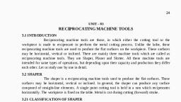
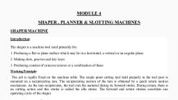
SHAPER AND PLANER, Introduction: , The shaper is a machine tool used primarily for: , Producing a flat or plane surface which may be in a horizontal, a vertical or an angular plane., 2. Making slots, grooves and key ways , 3. Producing contour of concave/convex or a combination of these
Page 2 :
Working Principle: The job is rigidly fixed on the machine table. The single point cutting tool held properly in the tool post is mounted on a reciprocating ram. The reciprocating motion of the ram is obtained by a quick return motion mechanism. As the ram reciprocates, the tool cuts the material during its forward stroke. During return, there is no cutting action and this stroke is called the idle stroke. The forward and return strokes constitute one operating cycle of the shaper.
Page 6 :
Construction, Base: It is the main body of the machine. It consist all element of machine. It works as pillar for other parts. Base is made by cast iron which can take all compressive loads. , Ram: It is the main part of the shaper machine. It holds the tool and provides the reciprocating motion to it. It is made by cast iron and move over ways on column. It is attached by the rocker arm which provide it motion in crank driven machine and if the machine is hydraulic driven it is attached by hydraulic housing., Tool head: It is situated at the front of the ram. Its main function is to hold the cutting tool. The tool can be adjusted on it by some of clamps. , Table: It is the metal body attached over the frame. Its main function is to hold the work piece and vice over it. It has two T slots which used to clamp vice and work piece over it.
Page 7 :
Clapper box: It carries the tool holder. The main function of clapper box is to provide clearance for tool in return stock. It prevents the cutting edge dragging the work piece while return stock and prevent tool wear. , Column: Column is attached to the base. It provides the housing for the crank slider mechanism. The slide ways are attached upper section of column which provide path for ram motion. , Cross ways: It consist vertical and horizontal table sideways which allow the motion of table. It is attach with some cross movement mechanism. , Stroke adjuster: It is attached below the table. It is used to control the stroke length which further controls the ram movement. , Table supports: These are attached front side of the table and used to support the weight of table during working.
Page 8 :
TYPE OF SHAPER, Types of Shaper: Shapers can classified into many types based on several criteria: , Based on the type of driving mechanism used , a) Crank and slotted lever driving mechanism type , b) Whitworth quick return driving mechanism type , c) Hydraulic driving mechanism type , 2) Based on the table design , a) Plain Shaper , b) Universal Shaper, 3) Based on the position of the reciprocating ram used , a) Horizontal shaping machine (Most common type of shaper used) , b) Vertical shaping machine , c) Travelling head shaping machine , 4) Based on the type of cutting stroke of the tool , a) Push out type Shaper , b) Draw cut type Types Shaper
Page 9 :
Quick Return Mechanism, Types A quick return mechanism is an system to produce a reciprocating effect such that time taken by system in return stroke is less time taken by it in the forward stroke. In quick return mechanism, a circular motion is converted into reciprocating motion just like crank and lever mechanism but it has return stroke time is different from forward stroke time. This mechanism is used in many machines. Some of them are shaper machines, slotter machines, screw press, mechanical actuator etc.With the help of quick return mechanism, the time needed to cutting is minimized.
Page 13 :
This mechanism changes the rotary motion to oscillatory motion like the crank and lever mechanism. The difference between the crank and lever mechanism and Whitworth mechanism is that in whitworth mechanism the return stroke is faster than the forward stroke while in the crank and lever mechanism the forward stroke is of same speed as that of return stroke. , Parts used in Whitworth mechanism :- , Slotted Bar. , 2) Slider , 3) Crank – It will rotate.
Page 14 :
Shaper Machine, Specifications , Length of Ram stroke: (457 mm), Range of Ram speeds: (12, 24, 40 & 72 strokes per minute) , Working surface of table: (483 mm * 330 mm), Max Table Travel – Horizontal: (610 mm), Max Table Travel – Vertical: (457 mm), Angular movement of table on either side: (600), Maximum size of Tool Shank in Tool Head: (51m * 21mm) , Maximum vertical travel of Tool Slide: (152 mm) , Maximum swivel of Tool Head: (600), Main Drive Motor: (3 H.P./ 950 rpm)
Page 15 :
CUTTING PARAMETERS OF A SHAPER, Cutting Speed , It is defined as the average linear speed of the tool during the cutting stroke in m/min, which depends on number of ram strokes ( or ram cycles) per minute and length of the stroke. , Feed , Feed f is the relative motion of the work piece in a direction perpendicular to the axis of the reciprocation of the arm. In shaper, feed is normally given to the work piece and can be automatic or manual. It is expressed in mm/double stroke or simply mm/stroke because no cutting is done in return stroke. , Depth of Cut Depth of cut d is the thickness of the material removed in one cut, in mm.
Page 16 :
PLANER, The planer or planing machine is a machine tool, which like the shaper produces flat surfaces in horizontal, vertical or inclined plane. The fundamental difference is that the planer operates with an action opposite to that of the shapers, i.e., the work piece reciprocates past one or more stationary single point cutting tools. Planers are meant for machining large sized work pieces, which cannot be machined by the shaping machines. The work table is moved back and forth on the bed beneath the cutting head either by mechanical means , such as a rack and pinion gear or by a hydraulic cylinder.
Page 17 :
CLASSIFICATION OF PLANNER, Planers are generally divided in to 5 types , Double housing planer , 2) Open side planer , 3) Edge type planer , 4) Divide table planer , 5) Pit type planer
Page 19 :
Parts of Planner, 1) BED :-Bed of a planer is large in size and heavy in weight. It supports the column and all other moving parts of machine. It is made slightly longer than twice the length of the table may be moved on it. There is a v shaped ways on the bed which help to reciprocate or back and forth motion to the table. , 2) TABLE :-Table supports the work and reciprocates along the bed. Table is made from cast iron. The top face of the table is accurately finished in order to locate the work correctly. T- slots are provided on the entire length of the table so that the work and work holding devices may be bolted upon it. , 3) COLUMN:- These are rigid box like vertical structure placed on each side of the bed and table. They are heavily ribbed to trace up severe force due to cutting. It also facilitate tool head mechanism. The cross rail may be made to slide up and down for accommodating different heights of work. , 4) CROSS :- RAIL It is rigid box like casting connecting the two columns. It may be raised or lowered on the face of housing and can be clamped at a desired position by manual or electrical clamping devices. It should remain absolutely parallel to the top surface of the table. , 5) TOOL HEAD :- Tool heads are mounted on the crossrail by saddle. The saddle may be made to move transversely on the cross rail to give cross feed. The clapper block is hinged at hinge pins to the clapper block and it holds the tool post in which the tool is clamped by straps.
Page 20 :
Work Holding devices used in Planner, Heavy duty vices , T-bolts and Clamps , Step blocks,T-bolts and Clamps, Poppets or stop pins and dogs , Angle plates , Planer centers, Planer Jacks , V- blocks , Stops Planer