Notes of 3rd Semester, EEM Range extension.pdf - Study Material
Page 1 :
Range extension of Ammeter, , 2.1.3. Ammeter Shunts. The basic mov, The coil winding of a basic movement is small and light and, can carry very small currents since the construction of an, accurate instrument with a moving coil to carry currents greater, than 100 mA is impracticable owing to the bulk and weight of, the coil that would be required., , When heavy currents are to be measured, the major part, of the current is bypassed through a low resistance called a, , "shunt". Fig. 2.5 shows the basic movement (meter) and its shunt’, , to produce an ammeter., The resistance of the shunt can be calculated using, conventional circuit analysis. See Fig. 2.5,, , where R,, = internal resistance of movement (ie, the coil) Q ;, , Ry, = cesistance of the shunt ; 9,, , £,, = Tm = full scale deflection current of movement, A ;, , J = current to be measured ; A., , ement of ad.c. ammeter isa PMMC 4’ Arsonval galvanontietey., , , , Fig. 2.5. Basic ammete: circuit., , 7,, = shunt current, A, , Since the shunt resistance is in parallel with the meter movement, the voltage drops across shunt and, , mavement must be the same., , or Fey Ra = TnRn oe Rag, Egy bey » nf 2.8), , But fy, = 1 — Jy: therefore we can write Ry = Rall — 1), sh = ty Fe, , 4 fit, —1= Rik, , ae AS hy or, , This ratio ef total current to the current in the, Muluplying power m= Il,, : =14+R,/R, , st, , A272), , Wy = 1 + RefRep ‘ A208), movement is called mudtipiyin 2 power of shit., , 29), wal 240)
Page 2 :
me A IND ph, , Resistance of shunt Ry, = Ryf(m — 1) +(2.11}, , The shunt resistance used with a d’Arsonval movement may consist of a coil of resistance wire within, the case of the Instrument, or it may be external shunt having a very low resistance., , Construction of Shunts. The general requirement for shunts are :, , (® the temperature co-efficient of shunt and instrument should be low and should be as nearly as possibly, the same ; :, , (ii) the resistance Of shunts should not vary with time,, , (iii) they should carry the current without excessive temperature rise,, , (iv) they should have a low thermal electromotive force with copper., , ‘Manganin’ is usually used for shunts of d.c. instruments as it gives low value of thermal emf with, copper although it is liable to corrosion and is difficult to solder. ‘Constantan’ is a useful material for a.c,, circuits since its comparatively high thermal emf, being unidirectional, is ineffective on these circuits., , The construction of shunts is the same as that of low resistance standards. Shunts for low currents, are enclosed in the meter casing but for currents above 200 A, they are mounted separately (so that heat, produced can be effectively dissipated)., , mA » Arsonval movement with an internal resistance of 100 Q is to be converted, Example 24. Al meter d’ Ars fe. Bl Oe aitamiinadl! MWhabmartianlans shauld ha osentGcd
Page 3 :
Range extension of Voltmeter, , 2.6. Voltmeter Multipliers. A d’Arsonval, basic meter movement is converted into a volimeter +, by connecting a series resistance with it, This semes, resistance is known as a muitiplier. The combination, of the meter movement and the multiplier is put across, — whose voltage is to be measured. (See Fig., , 3)., , The meliplier limits the current through the, meter so that it does nui exceed the value for full scale «_, deflection and thus prevents ‘he movement from being, , , , , ‘Suppiy, Load, , Seres resistance, [multiplier], , Fig. 2.9) Meter with a multiplier,, , damaged., _ The value of a multiplier, required to extend the vollage range, is ealeulated as under +, Let im deg = full segle deflection current of meter,, R,, = internal resistance of meter movement,, R, = multiplier resistance,, v= voltage across the meter movement for current J,, Y = full range voltage of instrument. ., For the circuit of Fig. 2.9, ve Ta Rn we(2,12), V=l(Rm + Rd (2.13), V-i,, 4 Ree is _ +R, 2.14), im m, We can also express the result in terms of multiplying factor of multiplier., st 5 ss V _bafR + Bed R, Multiplying factor for multiph woe a, P * ig ™ plier m=7) TR i+ R, eu2.15), Resistance of multiplier R,=(m-1) Rk, (2.16), , Hence for the measurement of voltage m times the yoltage range of the in: i iplyi, " iz strument, the series multiplying, resistance should be (m — 1) times the meter resistance. Thus to extend th i, i - : c, mca a voltage range to 10 times the, Construction of Multipliers. The essential requirements of ili, . + m :, (H their resistance should not change with time, ftoies RES, (ii) the change in their resistance with temperature should f, (it) they should be non-inductively wound for ac, es, aaa, , ae QR ued fr wilh ets ast
Page 5 :
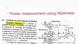
— Weeunualy winuing current x (impeaance oF load m we seconuary winuing circuit) (3.10), , 3.5. CURRENT TRANSFORMERS, , The current transformer is used with its, , primary winding connected in series with line, carrying the current to be measured and,, therefore, the primary current is dependant, upon the load connected to the system and is, not determined by the load (burden) connected, on the secondary winding of the current, transformer. The primary winding consists of, very few turns and, therefore, there is no, appreciable voltage drop across it. The, secondary winding of the current transformer, has larger number of turns, the exact number, being determined by the turns ratio. The, ammeter, or wattmeter current coil, are, connected directly across the secondary, winding terminals. Thus a current, , op, Supply : Load, Primary winding, , Ip, , , , , , , , , , , , , Pressure coil, (Ro), , To potential, “circuit, , ’ Watt meter, , Fig. 3.3 Use of C.T. for current and power measurement., , transformer operates its secondary winding nearly under short circuit conditions. One of the terminals of, the secondary winding is earthed-so as to protect equiqment and personnel in the vicinity in the event of, an insulation breakdown in the current transformer. Fig. 3.3 shows a circuit for measurement of current and, , power with a current transformer.
 Learn better on this topic