Page 2 :
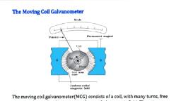
in the strengtn Of permanent waguew v-- several types of instruments., 9.4. Permanent Magnet Moving, , the same as that of the d’Arsonval type of galvanome’, is provided with a pointer and a scale., 9.4.1. Construction of PMMC In:, are shown in Fig. 9.1., Moving Coil. The moving coil is wou!, The coil is mounted on a rectangular aluminiu, , moves freely in the field of a permanent magnet. Most voltmeter coils, ammeter coils, however, are wound on non-magnetic former,, , the required electro-magnetic damping. Most, , because coil tums are effectively shorted by the ammeter shunt. The coil itself, therefore, provides electro., , magnetic damping., , Magnet Systems. There has been considerable, development in materials for permanent magnets and,, therefore, magnet assemblies have undergone a lot of change, in the recent past. Old style magnet system consisted of a, relatively long U shaped permanent magnets having soft iron, pole pieces. Owing tv development of materials like Alcomax, and Alnico, which have a high co-ercive force, it is possible, to use smaller magnet lengths and high field intensities. The, flux densities used in PMMC instruments vary from 0.1, Wb/m? to 1 Wb/m?. Thus in small instruments it is possible, to use a small coil having small number of tums and hence, a reduction in volume is achieved. Altematively in, instruments having a large scale length it is possible to, increase the air gap length to accommodate large number of, , tums., , Coil Instrument (PMMC). The permanent magnet Movin, ts. The working principle of these ; Coy, i ‘ rate type for d.c. measurements. © se instray, instrument is the most accu YP ters, the difference being that a direct reading inet, strung, struments. The general constructional features of this inst, en, , nd with many tums of enamelled or silk covered Copper yj, m former which is pivoted on jewelled bearings. The =, iS, , The movement of the coil is restricted in the above design. This is because no actual part of, , “0h y, , are wound on metal frames to Provig, kt, , Upper, control, spring, , Soft- steel, ring, , , , , , , , &, , , , , , , arith, , Y, , , , , , Moving, coil. », i, Permanent Core |, magnet |, Lower |, , control spring, , Fig. 9.2. Concentric magnet assembly. |, the ccil, , is allowed to reach the extreme Positions near the pole tips where, there is fringing field (owing to fring |, the flux density near the pole tips is smaller than that at the centre and also the field is not radial). ™, , the angular span of scale is restricted to 90°. In order to obtain longer movement of the pointer a, angular swing of the coil a concentric magnet construction as shown in Fig. 9.2 is used. Since t, , nd a Jonge!, fhe mag
Page 3 :
See re Me te Pieces and the steel yoke. This arrangements has the obvious advantage, dl ig ‘ y the external magnetic fields. It also eliminates the magnetic shunting effects, insteel panel construction, where Several meters operating side by side may affect each others’ readings., The need for magnetic shielding in the form of iron cases, is also eliminated by core magnet construction., , Control. When the coil is supported between two jewel bearings the control torque is provided by, two phosphor bronze hair springs. These springs also serve to lead current in and out of the coil. The control, torque is provided by the ribbon suspension as shown in Fig. 9.2, This method is comparatively new and “, is claimed to be advantageous as it eliminates bearing friction., , Damping. Damping torque is produced by movement of the aluminium former moving in the magnetic, field of the permanent magnet., , Pointer and Scale. The pointer is carried by the spindle and moves over a graduated scale. The pointer, is Giee wah construction and, apart from those used in some inexpensive instruments, has the section, over the scale twisted to form a fine bla ‘i This helps to reduce parallax errors in the reading of the scale.
Page 4 :
In many instruments such errors may be reduced further by careful atigpmvant of the ee blade ang ij, reflection in the mirror adjacent to scale. The weight of the instrument is normally counter balanced by Weighs, situated diametrically opposite and rigidly connected to it., , 9.4.2. Torque Equation. {he torque tor a moving coil instrument 1s derived in Art. 8. on Page 246, , deflecting torque T, = NB I dl = GI (9), where G =a constant = NB Id (92), The spring control provides a restoring (controlling) torque T. = KO (93), where K = spring constant., For final steady deflection T.=T, or GIl=kK@, Final steady deflection 8=(G/K)I (94), or current J = (K/G) @ (95), , As the deflection is directly proportional to the current passing through the meter (K and G being, constants) we get a uniform (linear) scale for the instrument., , Tr mirern_ammotare and Tae enn nn IMD 2-1 a * An
Page 5 :
AUSISUMILE 19 ALYY USCU UY AEE GUY US UNE axe Gtane snttnns wensaureneneves ie wee mentens eres wares ot8s ror, UU AIC 299), , 9.4.12. Aavantages and Disadvantages of PMMC Hnsiruments The 1 main advantages of PMMC, instruments are :, , 1. The scale is uniformly divided., 2. The power consumption is very low as 25 pW to 200 pW., , 3. The torque-weight ratio is high which gives a high accuracy. The accuracy is of the order of generally, 2 percent of full scale deflection., , 4. A single instrument may be used for many different current and voltage ranges by using different, values for shunts and multipliers., , 5. Since the operating forces are large on account of large flux densities which may be as high as, 0.5 Wb/m? the errors due to stray magnetic fields are small., , 6. Self-shielding magnets make the core magnet mechanism particularly useful in aircraft and aerospace, applications, where a multiplicity of instruments must be mounted in close proximity to each other. An example F, of this type of mounting may be in the cross pointer indicator, where as many as five mechanisms are mounted F, in one case to form a unified display. This, obviously, results in elimination of iron cases and the corresponding L, weight reduction are of great advantage in aircraft and aerospace instruments., , The chief disadvantages are :, , 1. These instruments are useful only for d.c. The torque reverses if the current reverses. If the instrament |, is connected to a.c., the pointer cannot follow the rapid reversals and the deflection corresponds to mean, , torque, which is zero. Hence these instruments cannot be used for a.c., , 2. The cost of these instruments is higher than that of moving iron instruments., OF Ahenmntaen ‘Tha ahemmatar ie a canveniant direct reading device for measurement of resistance. The: se