Page 1 :
- Measurement of Resistance, , , , , , ew of measurement, is as follows, , , , , , , The classification of resistances, from 1, (® Low Resistances. _Alltesistances of the « of 1-Q and under may be classified as low resistances.(ii) Medium Resistances. This class includes resistances from=1 Q° upwards to_about 0.1 MQ. es, , (iii) High Resistances. Resistances of the order of 0.1 MQ.and upwards are classified as high resistances. _, The classification outlined above is not rigid, but forms a basis for techniques, sollowes or measurement, , which may be different for different classes.
Page 2 :
pe, , MEASUREMENT OF LOW RESISTANCE, , Th ; anes ie D, , e Kelvin bridge is a modification of the, and provides greatly increased accuracy in measurement of low value, resistances. An understanding of the Kelvin bridge arrangement may, be obtained by a study of the difficulties that arise in a Wheatstone, bridge on account of the resistance of the leads and the contact, resistances while measuring low valued resistors., , Consider the bridge circuit shown in Fig. 7.15 where r represents, the resistance of the lead that connects the unknown resistance R to, standard resistance S. Two galvanometer connections indicated by, dotted lines, are possible. The connection may be either to point ‘Mm, or to point ‘n’. When the galvanometer is connected to point m, the, resistance, r, of thé connecting leads is addled to the standard resistance,, , , , , , , , S, resulting in indication of too low an indication for unknown H —t &, resistance R. When the connection is made to point n, the resistance,, r, is added to the unknown resistance resulting in indication of too Se if eE, , , , high a value for R., Suppose that instead of using point m, which gives a lowresult, Fig. 7.16. Illustrating principle of Kelvin's, , or n, which makes the result high, we make the galvanometer bridge., , connection to any intermediate point ‘d’as shown by full line in Fig. 7,11, If at point ‘d’ the resistance r, , is divided into two parts,"ry and ry, such that, , al P, a 138., 1 Q° s ,
Page 3 :
SLUT, , , , Then the presence of 1; the resistance of connecting leads, causes no error in the result, We have, , ie Mee (738, Ra na-ge Str) but ooo :, = nN P P, , , , =s—orn= opasnt ye Pand = peor,, nth P+Q ~ "> P+Q is P+O, , P, , *. We can write Eqn. 7.38(a) as (R + oe r) = 7 ( a7 a r ork oo” +(7.38b), , Therefore we conclude that making the galvanometer connection as at c, the resistance of leads does, not affect the result., , The process described above is obviously not a practical, way of achieving the desired result, as there would certainly be, a trouble in determining the correct point for galvanometer, connections. It does, however, suggest the simple modification,, that two actual resistance units of correct ratio be connected, between points m and n, the galvanometer be connected to the, junction of the resistors. This.is the actual Kelvin bridge, , ~ arrangement, which is shown in Fig. 7.17., , The Kelvin double bridge incorporates the idea of a second, set of ratio arms—hence the name double bridge—and the use, of four terminal resistors for the low resistance arms. Fig. 7.17, shows the schematic diagram of the Kelvin bridge. The first of, tatio arms is P and Q. The second set of ratio arms, p and q, is used to connect the galvanometer to a point d at the appropriate, potential between points m and n to eliminate the effect of Fig. 7.17. Kelvin double bridge., connecting lead of resistance r between the known resistance, R, and the standard resistance, S., , The ratio p/q is\made equal to P/Q. Under balance conditions there is no current through the, , galvanometer, which means that the voltage drop between.a and b, E,, is equal to the voltage drop Eynd, between a and c., , , , , , P (p+q)r, Ew => E. 2 eaeeaa, Now E,, P+0 ac and Ey. R+s+Ceor) (7.39), Ew, =1[R weal see |e [ pri’, and- es a phar I] R+ ptger «(7.40), For zero galvanometer deflection, Ey, = Euma, oe poy i [Ress Gee =1[R+— Pr, P+Q pt+qtr p+qtr, BoEE gg dre | ERA ND, 7 cS ot ptqtr|@ -2) w(7.41), , Now, if P/Q = p/q, Eqn. 7.41 becomes, R = 7 s we(7.42), , Egn. 7.42 is the usual working equation for the Kelvin bridge. It indicates that the resistance of connecting, lead, n has no effect on the measurement, provided that the two sets of ratio arms have equal ratios. Eqn., 7.41 is useful, however, as it shows the error that is introduced in case the ratios are not exactly equal. It, , indicates that it is desirable to keep r as small as possible in order to minimize the errors in case there is, a difference between ratios P/Q and p/q., , The effect of thermo-clectric emfs can be eliminated by making another measurement with the battery, connections reversed. The true value of R being the mean of the two readings, , «+ USED Se— menswremet— of: Low Revishucee
Page 4 :
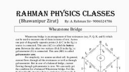
Measurement of medium resistance, , important device used in the, measurement of medium resistances is the Wheatstone bridge. A, Wheatstone bridge has been in use longer than almost any electrical, measuring instrument. It is still an accurateand reliable instrument and, is extensively used in industry. The Wheatstone bridge is an instrument, for making comparison measurements and operates upon a null indication, principle. This means the indication is independent of the calibration, of the null indicating instrument or any of its characteristics. For this, reason, very high degrees of accuracy can be acheived using Wheatstone, bridge. Accuracy of 0.1% is quite common with a Wheatstone bridge, as opposed to accuracies of 3% to 5% with ordinary ohmmeter for, measurement of medium resistances. Fig 7.3 shows the basic circuit of, a Wheatstone bridge. It has four resistive arms, consisting of resistances, P, Q, Rand S together with a source of emf (a battery) and a null detector,, usually a galvanometer G or other sensitive current meter. The current Fig. 7.3. Wheatstone bridge., through the galvanometer depends on the potential difference between points c and d. The bridge is said, to be balanced when there is no current through, the galvanometer or when the potential difference across, the galvanometer is zero. This occurs when the voltage from point ‘b’ to point ‘a’ equals the voltage from, point ‘d’ to point ‘b’; or, by referring to the other battery terminal, when the voltage from point ‘d’ to point, c equals the voltage from point ‘b’ to point sO, , , , For bridge balance, we can write :, , , , , , IP =1R TAL), For the galvanometer current to be zero, the following conditions also exist :, h=h= E, P+Q wh 7.12), and E, h=l=Rys5 (7.13), where E = emf of the battery., Combining Eqns. 7.11, 7.12 and 7.13 and simplifying, we obtain :, P R, P+Q R+S «.A7-14), from which OR = PS (7.15), , Eqn. 7.15 is the well known expression for the balance of wheatstone bridge. If three of the resistances, sre known, the fourth may “be determined from Eqn, 7.15 and we obtain :, , P, Ros, (7.16), , — Daknown Rerishre, 6 — -skoudard am, P$Q— Ratio arm, , Terese rt nee PETER ee
Page 5 :
Measurement of high resistance, , 25, MEGGER, Ratiometer ohmmeters, described earlier,, may be designed to cover, a wide range of resistances., The principle of ratiometer, ohmmeters is particularly, adapted to application in, , portable instruments, measuring insulation, resistance. This principle, forms the basis of, insulation testing, instrument known as, , Megger. The essential parts, of a Megger are shown in, Fig. 2.23. The current coil, , unknown, resistance, Ry, , Pole piece, , , , , , , , Lo, ™100, , \, , , , Ve M4, , Current coilla/, , Annular iron ring, , , , 7___Magnet, , , , , , , , , , , , , , Hand, , , , , , , , , , , , , , , , Fig. 2.23. Megger., , 0 driven, | generator, \\__ Magnet, [ Ntigaments, , is similar to that of the permanent magnet moving coil instrument. There are two voltage (potential) coils, V, and V,. The voltage coil V, embraces (threads over) the annular magnetic core. It is clear from Fig. 2.23, that voltage coil V, is in a weak magnetic field when the pointer is at ‘s>’ position and hence this coil can, , exert very little torque.
 Learn better on this topic