Page 3 :
Sharing of Information, Exchanging of Information, Communication is an act of sending or receiving Information, By Shrikant Hiremath
Page 5 :
When we communicate, we are sharing information. , This sharing can be local or remote ,between individuals., Local communication usually occurs face to face., While remote communication takes place over distance. which includes telephone, telegraph, and television, So that we call it as telecommunication means communication at a distance (tele is Greek for "far")., By Shrikant Hiremath
Page 6 :
Data refers to the raw facts that are collected., While information refers to processed data that enables us to take decisions. , The word data refers to any information which is presented in a form that is agreed and accepted upon by is creators and users. , Data can be any text, image, audio, video, and multimedia files. , Data generally are defined as information that is stored in digital form, By Shrikant Hiremath
Page 8 :
Data communications are the exchange of data between two devices via some form of transmission medium such as a wire cable. , For data communications to occur, the communicating devices must be part of a communication system made up of a combination of hardware (physical equipment) and software (programs)., We can also say that Data communications is the transmission, reception, and processing of digital information, By Shrikant Hiremath
Page 11 :
Sender: A sender is a computer or any such device which is capable of sending data over a network. It can be a computer, mobile phone, smartwatch, walkie- talkie, video recording device, etc., Receiver: A receiver is a computer or any such device which is capable of receiving data from the network. It can be any computer, printer, laptop, mobile phone, television, etc. In computer communication, the sender and receiver are known as nodes in a network., By Shrikant Hiremath
Page 12 :
Message: It is the data or information that needs to be exchanged between the sender and the receiver. Messages can be in the form of text, number, image, audio, video, multimedia, etc., Communication media: It is the path through which the message travels between source and destination. It is also called medium or link which is either wired or wireless. For example, a television cable, telephone cable,satellite link, microwaves, etc. , Protocols: It is a set of rules that need to be followed by the communicating parties in order to have successful and reliable data communication., By Shrikant Hiremath
Page 13 :
DATA REPRESENTATION, 1. Text , Text includes combination of alphabets in small case as well as upper case. , It is stored as a pattern of bits. Prevalent encoding system : ASCII, Unicode , , 2. Numbers , Numbers include combination of digits from 0 to 9. , It is stored as a pattern of bits. Prevalent encoding system : ASCII, Unicode, By Shrikant Hiremath
Page 14 :
3. Images , An image is worth a thousand words‖ is a very famous saying. In computers images are digitally stored. , A Pixel is the smallest element of an image. To put it in simple terms, a picture or image is a matrix of pixel elements. , The pixels are represented in the form of bits. Depending upon the type of image (black n white or color) each pixel would require different number of bits to represent the value of a pixel. , The size of an image depends upon the number of pixels (also called resolution) and the bit pattern used to indicate the value of each pixel. , Example: if an image is purely black and white (two color) each pixel can be represented by a value either 0 or 1, so an image made up of 10 x 10 pixel elements would require only 100 bits in memory to be stored., On the other hand an image that includes gray may require 2 bits to represent every pixel value (00 - black, 01 – dark gray, 10 – light gray, 11 –white). So the same 10 x 10 pixel image would now require 200 bits of memory to be stored. , Commonly used Image formats : jpg, png, bmp, etc, By Shrikant Hiremath
Page 15 :
4. Audio , Data can also be in the form of sound which can be recorded and broadcasted. Example: What we hear on the radio is a source of data or information. , Audio data is continuous, not discrete. , 5. Video , Video refers to broadcasting of data in form of picture or movie, By Shrikant Hiremath
Page 16 :
DATA FLOW, Data communication happens in the form of signals between two or more computing devices or nodes. , The transfer of data happens over a point-to-point or multipoint communication channel. , Data communication between different devices are broadly categorised into 3 types: , Simplex communication., Half- duplex communication., Full-duplex communication., By Shrikant Hiremath
Page 17 :
Simplex, It is a one way or unidirectional communication between two devices in which one device is sender and other one is receiver. , Devices use the entire capacity of the link to transmit the data. , It is like a one way street where vehicles can move in only one direction. , For example, data entered through a keyboard or audio sent to a speaker are one way communications., By Shrikant Hiremath
Page 19 :
Half-duplex, It is two way or bidirectional communication between two devices in which both the devices can send and receive data or control signals in both directions, but not at the same time., When one device is sending other can only receive and vice-versa, By Shrikant Hiremath
Page 22 :
Full Duplex, It is two way or bidirectional communication in which both devices can send and receive data simultaneously., It is like a two way road where vehicles can go in both directions at the same time., This type of communication channel is employed to allow simultaneous communication, for example, in our mobile phones and landline telephones. , The capacity of the transmission link is shared between the signals going in both directions. , This can be done either by using two physically separate simplex lines — one for sending and other for receiving, or the capacity of the single channel is shared between the signals travelling in different directions., By Shrikant Hiremath
Page 24 :
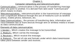
COMPUTER NETWORK, Definition: , A computer network can be defined as a collection of nodes. A node can be any device capable of transmitting or receiving data. The communicating nodes have to be connected by communication links. , A Computer network should ensure , reliability of the data communication process, security of the data , performance by achieving higher throughput and smaller delay times, By Shrikant Hiremath
Page 25 :
Type of Connection, Point-to-Point , A point-to-point connection provides a dedicated link between two devices. , The entire capacity of the link is reserved for transmission between those two devices., Most point-to-point connections use an actual length of wire or cable to connect the two ends, but other options, such as microwave or satellite links, are also possible., By Shrikant Hiremath
Page 27 :
Multipoint , A multipoint (also called multidrop) connection is one in which more than two specific devices share a single link., In a multipoint environment, the capacity of the channel is shared, either spatially or temporally. , If several devices can use the link simultaneously, it is a spatially shared connection. , If users must take turns, it is a timeshared connection., By Shrikant Hiremath
Page 29 :
Network Topologies, In computer networking, topology refers to the layout of connected devices., i.e. how the computers, cables, and other components within a data communications network are interconnected, both physically and logically., The physical topology describes how the network is actually laid out, and the logical topology describes how the data actually flow through the network., Two most basic topologies are point-to-point and multipoint., star, bus, ring, mesh and hybrid are the other categories of topology, By Shrikant Hiremath
Page 30 :
Mesh topology, In a mesh topology, every device has a dedicated point-to-point link to every other device. , The term dedicated means that the link carries traffic only between the two devices it connects., Messages sent on a mesh network can take any of several possible paths from source to destination., mesh network in which every device connects to every other is called a full mesh. , A mesh network with n nodes must have n(n-1)/2 links and each node must have n-1 I/O ports (links)., By Shrikant Hiremath
Page 32 :
Star topology, A star topology is designed with each node (file server, workstations, and peripherals) connected directly to a central network hub, switch, or concentrator. , Data on a star network passes through the hub, switch, or concentrator before continuing to its destination. , The hub, switch, or concentrator manages and controls all functions of the network., By Shrikant Hiremath
Page 34 :
Bus topology, Bus networks use a common backbone to connect all devices. , A single cable, (the backbone) functions as a shared communication medium that devices attach or tap into with an interface connector., A device wanting to communicate with another device on the network sends a broadcast message onto the wire that all other devices see, but only the intended recipient actually accepts and processes the message. , The bus topology is the simplest and most common method of interconnecting computers. , The two ends of the transmission line never touch to form a complete loop., A bus topology is also known as multidrop or linear bus or a horizontal bus., By Shrikant Hiremath
Page 36 :
Ring Topology, In a ring network (sometimes called a loop), every device has exactly two neighbors for communication purposes. , All messages travel through a ring in the same direction (either "clockwise" or "counter clockwise"). , All the stations are interconnected in series to form a closed loop or circle. , Transmissions are unidirectional and must propagate through all the stations in the loop. , Each computer acts like a repeater and the ring topology is similar to bus or star topologies., By Shrikant Hiremath
Page 38 :
Hybrid Topology, This topology (sometimes called mixed topology) is simply combining two or more of the traditional topologies to form a larger, more complex topology. , Main aim is being able to share the advantages of different topologies., By Shrikant Hiremath
Page 41 :
Local Area Network, A local area network (LAN) is a network that connects computers and devices in a limited geographical area such as home, school, computer laboratory, office building, or closely positioned group of buildings. , LANs use a network operating system to provide two-way communications at bit rates in the range of 10 Mbps to 100 Mbps. , In addition to operating in a limited space, LANs are also typically owned, controlled, and managed by a single person or organization. , They also tend to use certain connectivity technologies, primarily Ethernet and Token Ring., By Shrikant Hiremath
Page 43 :
Advantages of LAN:, Share resources efficiently, Individual workstation might survive network failure if it doesn’t rely upon others, Component evolution independent of system evolution, Support heterogeneous hardware/software, Access to other LANs and WANs, High transfer rates with low error rates, By Shrikant Hiremath
Page 44 :
Metropolitan Area Network, A metropolitan area network (MAN) is a network with a size between a LAN and a WAN. , It normally covers the area inside a town or a city. , It is designed for customers who need a high-speed connectivity, normally to the Internet, and have endpoints spread over a city or part of city., By Shrikant Hiremath
Page 46 :
Wide Area Network, A wide area network (WAN) provides long-distance transmission of data, image, audio,and video information over large geographic areas that may comprise a country, a continent,or even the whole world., Generally, telecommunication networks are Wide Area Network. , These networks provide connectivity to MANs and LANs. , Since they are equipped with very high speed backbone, WANs use very expensive network equipment., By Shrikant Hiremath
Page 48 :
Internetwork, A network of networks is called an internetwork, or simply the internet. It is the largest network in existence on this planet., The internet hugely connects all WANs and it can have connection to LANs and Home networks. , Internet enables its users to share and access enormous amount of information worldwide. , It uses WWW, FTP, email services, audio, and video streaming etc. , At huge level, internet works on Client-Server model., Internet is widely deployed on World Wide Web services using HTML linked pages and is accessible by client software known as Web Browsers. , When a user requests a page using some web browser located on some Web Server anywhere in the world, the Web Server responds with the proper HTML page. , The communication delay is very low., By Shrikant Hiremath
Page 49 :
Internet is serving many proposes and is involved in many aspects of life. Some of them are:, Web sites , E-mail , Instant Messaging , Blogging , Social Media , Marketing , Networking , Resource Sharing , Audio and Video Streaming, By Shrikant Hiremath
Page 50 :
NETWORK MODELS, In the study of computer networks it is essential to study the way our networks work., Computer networks are operated by network models., Most prominently the OSIRM and the TCP/ IP Model., By Shrikant Hiremath
Page 51 :
CONCEPT OF LAYERED TASK, The main objective of a computer network is to be able to transfer the data from sender to receiver. This task can be done by breaking it into small sub tasks, each of which are well defined., Each subtask will have its own process or processes to do and will take specific inputs and give specific outputs to the subtask before or after it. In more technical terms we can call these sub tasks as layers., By Shrikant Hiremath
Page 53 :
The Example shows, Sender, Receiver & Carrier, Hierarchy of layers, At the sender site, the activities take place in the following descending order:, Higher Layer: The sender writes the letter along with the sender and receivers address and put it in an envelope and drop it in the mailbox., Middle Layer: The letter is picked up by the post man and delivered to the post office, Lower Layer: The letters at the post office are sorted and are ready to be transported through a carrier., By Shrikant Hiremath
Page 54 :
During transition the letter may be carried by truck, plane or ship or a combination of transport modes before it reaches the destination post office., At the Receiver site, the activities take place in the following ascending order:, Lower Layer: The carrier delivers the letter to the destination post office, Middle Layer: After sorting, the letter is delivered to the receivers mail box, Higher Layer: The receiver picks up the letter, opens the envelope and reads it., By Shrikant Hiremath
Page 55 :
Hierarchy of layers: The activities in the entire task are organized into three layers. Each activity at the sender or receiver side occurs in a particular order at the hierarchy., The important and complex activities are organized into the Higher Layer and the simpler ones into middle and lower layer., By Shrikant Hiremath
Page 56 :
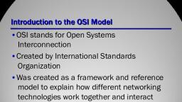
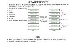
OPEN SYSTEMS INTER MODEL (OSI), The Open Systems Interconnection (OSI) Model was developed by International Organization for Standardization (ISO). , ISO is the organization, OSI is the model , It was developed to allow systems with different platforms to communicate with each other. Platform could mean hardware, software or operating system. , It is a network model that defines the protocols for network communications. , It is a hierarchical model that groups its processes into layers. It has 7 layers as follows: (Top to Bottom) , 1. Application Layer , 2. Presentation Layer , 3. Session Layer , 4. Transport Layer , 5. Network Layer , 6. Data Link Layer , 7. Physical Layer , Each layer has specific duties to perform and has to co-operate with the layers above and below it., By Shrikant Hiremath
Page 58 :
Application Layer, The application layer is responsible for �providing services to the user., And facilitates , Communication between OS and application, Application data generated here, Application layer refers to application layer protocol, Example : HTTP.SMTP,FTP, By Shrikant Hiremath
Page 59 :
Presentation Layer, Translation , The sending and receiving devices may run on different platforms (hardware, software and operating system). Hence it is important that they understand the messages that are used for communicating. Hence a translation service may be required which is provided by the Presentation layers, Encryption , It is the process of transforming the original message to change its meaning before sending it. The reverse process called decryption has to be performed at the receiving end to recover the original message from the encrypted message., Compression , Compression ensures faster data transfer. The data compressed at sender has to be decompressed at the receiving end, both performed by the Presentation layer., By Shrikant Hiremath
Page 60 :
Session Layer, Session layer, some times called the dialog controller provides mechanism for controlling the dialogue between the two end systems. It defines how to start, control and end conversations (called sessions) between applications., Session responsibilities include network log-on and log-off procedures and user authentication, By Shrikant Hiremath
Page 61 :
Transport Layer, The transport layer takes care of process to process delivery of data and makes sure that it is intact and in order. , At the sending side, the transport layer receives data from the session layer., The Transport layer is responsible for segmentation and reassembly of the message into segments which bear sequence numbers. This numbering enables the receiving transport layer to rearrange the segments in proper order. , Flow Control & Error control: the transport layer also carries out flow control and error control functions, The data can be transported in a connection oriented or connectionless manner. If the connection is connection oriented then all segments are received in order else they are independent of each other and are received out of order and have to be rearranged., By Shrikant Hiremath
Page 62 :
Network Layer, The network layer makes sure that the data is delivered to the receiver despite multiple intermediate devices. , The network layer is responsible for source to destination of delivery of data. Hence it may have to route the data through multiple networks via multiple intermediate devices. In order to achieve this the network layer relies on two things: , Logical Addressing , Routing, By Shrikant Hiremath
Page 63 :
Logical Addressing , The network layer uses logical address commonly known as IP address to recognize devices on the network. , An IP address is a universally unique address which enables the network layer to identify devices outside the sender‘s network. , The header appended by the network layer contains the actual sender and receiver IP address. , , Routing , Each packet is independent of the other and may travel using different routes to reach the receiver hence may arrive out of turn at the receiver. , Hence every intermediate node which encounters a packet tries to compute the best possible path for the packet. , This process of finding the best path is called as Routing., By Shrikant Hiremath
Page 64 :
Data Link Layer, The Data Link layer adds reliability to the physical layer by providing error detection and correction mechanisms. , On the sender side, the Data Link layer receives the data from Network Layer and divides the stream of bits into fixed size manageable units called as Frames and sends it to the physical layer., , Physical Addressing , The Data link layer appends the physical address in the header of the frame before sending it to physical layer. , The physical address contains the address of the sender and receiver., , Error control , The data link layer imposes error control mechanism to identify lost or damaged frames, duplicate frames and then retransmit them. , Error control information is present in the trailer of a frame. , , Access Control , The data link layer imposes access control mechanism to determine which device has right to send data in an multipoint connection scenario., By Shrikant Hiremath
Page 65 :
Physical Layer, On the sender side, the physical layer receives the data from Data Link Layer and encodes it into signals to be transmitted onto the medium. , Representation of bits , The physical layer is concerned with transmission of signals from one device to another which involves converting data (1‘s & 0‘s) into signals and vice versa. It is not concerned with the meaning or interpretation of bits. , Data rate , The physical layer defines the data transmission rate i.e. number of bits sent per second. It is the responsibility of the physical layer to maintain the defined data rate. , Synchronization of bits , To interpret correct and accurate data the sender and receiver have to maintain the same bit rate and also have synchronized clocks. , Line configuration , The physical layer defines the nature of the connection .i.e. a point to point link, or a multi point link. , Physical Topology , The physical layer defines the type of topology in which the device is connected to the network. In a mesh topology it uses a multipoint connection and other topologies it uses a point to point connection to send data. , Transmission mode , The physical layer defines the direction of data transfer between the sender and receiver. Two devices can transfer the data in simplex, half duplex or full duplex mode, By Shrikant Hiremath
Page 66 :
TCP/IP MODEL, It is also called as the TCP/IP protocol suite. It is a collection of protocols. , IT is a hierarchical model, ie. There are multiple layers and higher layer protocols are supported by lower layer protocols. , It existed even before the OSI model was developed. , Originally had four layers (bottom to top): , 1. Host to Network Layer , 2. Internet Layer , 3. Transport Layer , 4. Application Layer, By Shrikant Hiremath
Page 68 :
The structure TCP/IP model is very similar to the structure of the OSI reference model. The OSI model has seven layers where the TCP/IP model has four layers. , The Application layer of TCP/IP model corresponds to the Application Layer of Session, Presentation & Application Layer of OSI model. , The Transport layer of TCP/IP model corresponds to the Transport Layer of OSI model , The Network layer of TCP/IP model corresponds to the Network Layer of OSI model , The Host to network layer of TCP/IP model corresponds to the Physical and Data link Layer of OSI model., By Shrikant Hiremath
Page 70 :
Functions of the Layers of TCP/IP model, Host to Network Layer , This layer is a combination of protocols at the physical and data link layers. It supports all standard protocols used at these layers., By Shrikant Hiremath
Page 71 :
Internet Layer , Its job is to permit hosts to inject packets into any network and have they travel independently to the destination (potentially on a different network). , They may even arrive in a different order than they were sent, in which case it is the job of higher layers to rearrange them, if in-order delivery is desired. , The internet layer defines an official packet format and protocol called IP (Internet Protocol). , The job of the internet layer is to deliver IP packets where they are supposed to go. , Packet routing is clearly the major issue here, as is avoiding congestion., IP is a combination of four protocols: , 1. ARP , 2. RARP , 3. ICMP , 4. IGMP, By Shrikant Hiremath
Page 72 :
Transport Layer , Transport layer protocols are responsible for transmission of data running on a process of one machine to the correct process running on another machine. , The transport layer contains three protocols: , 1. TCP , 2. UDP , 3. SCTP, By Shrikant Hiremath
Page 74 :
Data and Signal, Computer networks are designed to transfer data from one point to another. , During transit data is in the form of electromagnetic signals. , Hence it is important to study data and signals before we move to further concepts in data communication. , To be transmitted, data must be transformed to electromagnetic signals., By Shrikant Hiremath
Page 75 :
Data can be Analog or Digital. , 1. Analog data refers to information that is continuous., ex. sounds made by a human voice , 2. Digital data refers to information that has discrete states. Digital data take on discrete values. , For example, data are stored in computer memory in the form of 0s and 1s, By Shrikant Hiremath
Page 76 :
Signals can be of two types:, 1. Analog Signal: They have infinite values in a range. , 2. Digital Signal: They have limited number of defined values, By Shrikant Hiremath
Page 77 :
ANALOG SIGNAL, An analog signal has infinitely many levels of intensity over a period of time. , As the wave moves from value A to value B, it passes through and includes an infinite number of values along its path. , A simple analog signal is a sine wave that cannot be further decomposed into simpler signals., By Shrikant Hiremath
Page 78 :
Characteristics of an Analog Signal, Peak Amplitude , The amplitude of a signal is the absolute value of its intensity at time t , The peak amplitude of a signal is the absolute value of the highest intensity. , The amplitude of a signal is proportional to the energy carried by the signal, By Shrikant Hiremath
Page 79 :
Frequency , Frequency refers to the number of cycles completed by the wave in one second. , Period refers to the time taken by the wave to complete one cycle., By Shrikant Hiremath
Page 80 :
Phase , Phase describes the position of the waveform with respect to time , Phase indicates the forward or backward shift of the waveform from the axis , It is measured in degrees or radian , The figure shows the sine waves with same amplitude and frequency but different phases, By Shrikant Hiremath
Page 81 :
Relation between Frequency & Period , Frequency & Period are inverse of each other. , It is indicated by the following formula: , , , , Example1. A wave has a frequency of 100hz. Its period(T) is given by , T = 1/ F = 1/ 100 = 0.01 sec , Example2. A wave completes its one cycle in 0.25 seconds. Its frequency is given by , F = 1 / T = 1 / 0.25 = 4 Hz, By Shrikant Hiremath
Page 82 :
Wavelength , The wavelength of a signal refers to the relationship between frequency (or period) and propagation speed of the wave through a medium. , The wavelength is the distance a signal travels in one period. , It is given by , Wavelength(λ) = Propagation Speed X Period , OR , Wavelength(λ) =Propagation Speed X 1/Frequency , It is represented by the symbol : λ (pronounced as lamda) , It is measured in micrometers , It varies from one medium to another., By Shrikant Hiremath
Page 83 :
Digital Signal, Information can also be explained in the form of a digital signal. , A digital signal can be explained with the help of following points:, A digital is a signal that has discrete values. , The signal will have value that is not continuous., By Shrikant Hiremath
Page 84 :
Characteristics of an Analog Signal, LEVEL , Information in a digital signal can be represented in the form of voltage levels. , Ex. In the signal shown below, a 1 is represented by a positive voltage and 0is represented by a Zero voltage., By Shrikant Hiremath
Page 85 :
BIT LENGTH or Bit Interval (Tb) , It is the time required to send one bit. , It is measured in seconds., By Shrikant Hiremath
Page 86 :
Baud Rate , It is the rate of Signal Speed, i.e the rate at which the signal changes. , A digital signal with two levels 0 & 1 will have the same baud rate and bit rate & bit rate., By Shrikant Hiremath
Page 87 :
The diagram shows three signal of period (T) 1 second , a) Signal with a bit rate of 8 bits/ sec and baud rate of 8 baud/sec , b) Signal with a bit rate of 16 bits/ sec and baud rate of 8 baud/sec , c) Signal with a bit rate of 16 bits/ sec and baud rate of 4 baud/sec, By Shrikant Hiremath
Page 88 :
Time Domain and Frequency domain representation of signals, A sine wave can be represented either in the time domain or frequency domain. , The time-domain plot shows changes in signal amplitude with respect to time. It indicates time and amplitude relation of a signal. , The frequency-domain plot shows signal frequency and peak amplitude. , The figure below show time and frequency domain plots of three sine waves. , A complete sine wave in the time domain can be represented by one single spike in the frequency domain, By Shrikant Hiremath
Page 90 :
TYPES OF CHANNELS:, Each composite signal has a lowest possible (minimum) frequency and a highest possible (maximum) frequency. , From the point of view of transmission, there are two types of channels: , 1.Low pass Channel , This channel has the lowest frequency as 0 and highest frequency as some non-zero frequency f1. , This channel can pass all the frequencies in the range 0 to f1. , 2.Band pass channel , This channel has the lowest frequency as some non-zero frequency f1 and highest frequency as some non-zero frequency f2. , This channel can pass all the frequencies in the range f1 to f2., By Shrikant Hiremath
Page 92 :
Transmission of Digital signal, Digital signal can be transmitted in the following two ways: , Baseband Transmission , Broad band Transmission, By Shrikant Hiremath
Page 93 :
BANDWIDTH OF A SIGNAL, Bandwidth can be defined as the portion of the electromagnetic spectrum occupied by the signal , It may also be defined as the frequency range over which a signal is transmitted. , Different types of signals have different bandwidth. Ex. Voice signal, music signal, etc , Bandwidth of analog and digital signals are calculated in separate ways; analog signal bandwidth is measured in terms of its frequency (hz) but digital signal bandwidth is measured in terms of bit rate (bits per second, bps) , Bandwidth of signal is different from bandwidth of the medium/channel, By Shrikant Hiremath
Page 95 :
Bandwidth of a digital signal, It is defined as the maximum bit rate of the signal to be transmitted. , It is measured in bits per second., By Shrikant Hiremath
Page 96 :
BANDWIDTH OF A CHANNEL, A channel is the medium through which the signal carrying information will be passed. , In terms of analog signal, bandwidth of the channel is the range of frequencies that the channel can carry. , In terms of digital signal, bandwidth of the channel is the maximum bit rate supported by the channel. i.e. the maximum amount of data that the channel can carry per second. , The bandwidth of the medium should always be greater than the bandwidth of the signal to be transmitted else the transmitted signal will be either attenuated or distorted or both leading in loss of information. , The channel bandwidth determines the type of signal to be transmitted i.e. analog or digital., By Shrikant Hiremath
Page 97 :
THE MAXIMUM DATA RATE OF A CHANNEL, Data rate depends on three factors: , The bandwidth available, The level of the signals we use , The quality of the channel (the level of noise) , The quality of the channel indicates two types: , a) A Noiseless or Perfect Channel , An ideal channel with no noise. , The Nyquist Bit rate derived by Henry Nyquist gives the bit rate for a Noiseless Channel. , b) A Noisy Channel , A realistic channel that has some noise. , The Shannon Capacity formulated by Claude Shannon gives the bit rate for a Noisy Channel, By Shrikant Hiremath
Page 98 :
Nyquist Bit Rate, The Nyquist bit rate formula defines the theoretical maximum bit rate for a noiseless channel , Bitrate = 2 x Bandwidth x Log2 L , Where, , Bitrate is the bitrate of the channel in bits per second , Bandwidth is the bandwidth of the channel , L is the number of signal levels., By Shrikant Hiremath
Page 99 :
Example What is the maximum bit rate of a noiseless channel with a bandwidth of 5000 Hz transmitting a signal with two signal levels., Solution: The bit rate for a noiseless channel according to Nyquist Bit rate can be calculated as follows: , BitRate = 2 x Bandwidth x Log2 L , = 2 x 5000 x log2 2 , = 10000 bps, By Shrikant Hiremath
Page 100 :
Shannon Capacity, The Shannon Capacity defines the theoretical maximum bit rate for a noisy channel , Capacity=bandwidth X log2 (1 +SNR) , Where, , Capacity is the capacity of the channel in bits per second , Bandwidth is the bandwidth of the channel , SNR is the Signal to Noise Ratio , Shannon Capacity for calculating the maximum bit rate for a noisy channel does not consider the number of levels of the signals being transmitted as done in the Nyquist bit rate., By Shrikant Hiremath
Page 101 :
Calculate the bit rate for a noisy channel with SNR 300 and bandwidth of 3000Hz Solution: , The bit rate for a noisy channel according to Shannon Capacity can be calculated as follows: , Capacity = bandwidth X log2 (1 +SNR) , = 3000 x log2 (1 + 300) , = 3000 x log2 ( 301) , = 3000 x 8.23 , = 24,690bps, By Shrikant Hiremath
Page 102 :
Signal-to-Noise Ratio (SNR), The signal-to-noise ratio is defined as, SNR=average signal power/average noise power, , SNR is actually the ratio of what is wanted (signal) to what is not wanted (noise)., A high SNR means the signal is less corrupted by noise a low SNR means the signal is more corrupted by noise., Because SNR is the ratio of two powers, it is often described in decibel units,, SNRdB, defined as, SNRdB = 10log10 SNR, By Shrikant Hiremath
Page 104 :
Line Encoding, It is the process of converting Digital data into digital signal. , In other words, it is converting of binary data(i.e. A sequence of bits) into digital signal (i.e. a sequence of discrete, discontinuous voltage pulses), By Shrikant Hiremath
Page 106 :
Unipolar, In a unipolar scheme, all the signal levels are on one side of the time axis, either above or below., NRZ (Non-Return-to-Zero) Traditionally, a unipolar scheme was designed as a non-return-to-zero (NRZ) scheme in which the positive voltage defines bit 1 and the zero voltage defines bit O. , It is called NRZ because the signal does not return to zero at the middle of the bit., By Shrikant Hiremath
Page 107 :
Polar NRZ, In polar schemes, the voltages are on the both sides of the time axis. , For example, the voltage level for 0 can be positive and the voltage level for I can be negative., Non-Return-to-Zero (NRZ) In polar NRZ encoding, we use two levels of voltage amplitude., By Shrikant Hiremath
Page 108 :
Bipolar - AMI and Pseudoternary, This coding scheme uses 3 voltage levels: +, 0, -, to represent the symbols , Voltage level for one symbol is at 0 and the other alternates between + & -. , Bipolar Alternate Mark Inversion (AMI) - the 0 symbol is represented by zero voltage and the 1 symbol alternates between +V and -V. , Pseudoternary is the reverse of AMI, By Shrikant Hiremath
Page 109 :
Multilevel, Here the number of data bits is increased per symbol to increase the bit rate. , 2 types of data element a 1 or a 0 are available, it can be combined into a pattern of n elements to create 2m symbols. , Using L signal levels we can have n signal elements to create Ln signal elements. The following possibilities can occur: , With 2m symbols and Ln signals: , If 2m > Ln then we cannot represent the data elements, we don‘t have enough signals. , If 2m = Ln then we have an exact mapping of one symbol on one signal. , If 2m < Ln then we have more signals than symbols and we can choose the signals that are more distinct to represent the symbols and therefore have better noise immunity and error detection as some signals are not valid, By Shrikant Hiremath
Page 112 :
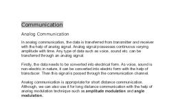
Modulation, The Process of converting analog data to analog signal is called Modulation. , Modulation is used to send an information bearing signal over long distances. , Modulation is the process of varying some characteristic of a periodic wave with an external signal called carrier signal. , These carrier signals are high frequency signals and can be transmitted over the air easily and are capable of traveling long distances. , The characteristics (amplitude, frequency, or phase) of the carrier signal are varied in accordance with the information bearing signal(analog data). , The information bearing signal is also known as the modulating signal. , The modulating signal is a slowly varying – as opposed to the rapidly varying carrier frequency., By Shrikant Hiremath
Page 113 :
Types of Modulation:, Signal modulation can be divided into two broad categories: , Analog modulation and , Digital modulation. , Analog or digital refers to how the data is modulated onto a sine wave. , If analog audio data is modulated onto a carrier sine wave, then this is referred to as analog modulation. , Digital modulation is used to convert digital data to analog signal. Ex ASK, FSK, PSK., By Shrikant Hiremath
Page 114 :
Analog Modulation can be accomplished in three ways: , 1. Amplitude modulation (AM) , 2. Frequency modulation (FM) , 3. Phase modulation (PM), By Shrikant Hiremath
Page 115 :
Amplitude modulation (AM) , Amplitude modulation is a type of modulation where the amplitude of the carrier signal is varied in accordance with modulating signal. , The envelope, or boundary, of the amplitude modulated signal embeds modulating signal. , Amplitude Modulation is abbreviated AM., By Shrikant Hiremath
Page 117 :
Frequency modulation (FM) , Frequency modulation is a type of modulation where the frequency of the carrier is varied in accordance with the modulating signal. The amplitude of the carrier remains constant. , The information-bearing signal (the modulating signal) changes the instantaneous frequency of the carrier. Since the amplitude is kept constant, FM modulation is a low-noise process and provides a high quality modulation technique which is used for music and speech in hi-fidelity broadcasts. , Frequency Modulation is abbreviated FM., By Shrikant Hiremath
Page 119 :
Phase modulation (PM). , In phase modulation, the instantaneous phase of a carrier wave is varied from its reference value by an amount proportional to the instantaneous amplitude of the modulating signal. , Phase Modulation is abbreviated PM., By Shrikant Hiremath
Page 121 :
Digital Modulation Types(Digital to Analog signal conversion), Digital modulation is used to convert digital data to analog signal. , It can be accomplished in the following ways: , 1. ASK , 2. FSK , 3. PSK , 4. QAM, By Shrikant Hiremath
Page 122 :
Amplitude Shift Keying (ASK), In amplitude shift keying, the amplitude of the carrier signal is varied to create signal elements. , Both frequency and phase remain constant while the amplitude changes. , Binary ASK (BASK) , ASK is normally implemented using only two levels and is hence called binary amplitude shift keying. , Bit 1 is transmitted by a carrier of one particular amplitude. , To transmit Bit 0 we change the amplitude keeping the frequency is kept constant, By Shrikant Hiremath
Page 124 :
Frequency Shift Keying (FSK), In Frequency shift keying, we change the frequency of the carrier wave. , Bit 0 is represented by a specific frequency, and bit 1 is represented by a different frequency. , In the figure below frequency used for bit 1 is higher than frequency used for bit 0, By Shrikant Hiremath
Page 125 :
Phase Shift Keying (PSK), Phase shift keying (PSK) is a method of transmitting and receiving digital signals in which the phase of a transmitted signal is varied to convey information. , Both amplitude and frequency remain constant as the phase changes. , The simplest from of PSK has only two phases, 0 and 1. , If the phase of the wave does not change, then the signal state stays the same (low or high). , If the phase of the wave changes by 180 degrees, that is, if the phase reverses, then the signal state changes (from low to high or from high to low), By Shrikant Hiremath
Page 126 :
QAM, The concept of Quadrature Amplitude Modulation (QAM) involves use of two carriers, one for phase and the other for quadrature, with different amplitude levels for each carrier. , It is a combination of ASK & PSK., By Shrikant Hiremath
Page 128 :
Multiplexing, What is Multiplexing?, Multiplexing is a technique used to combine and send the multiple data streams over a single medium. The process of combining the data streams is known as multiplexing and hardware used for multiplexing is known as a multiplexer., Multiplexing is achieved by using a device called Multiplexer (MUX) that combines n input lines to generate a single output line. Multiplexing follows many-to-one, i.e., n input lines and one output line., By Shrikant Hiremath
Page 129 :
The 'n' input lines are transmitted through a multiplexer and multiplexer combines the signals to form a composite signal., The composite signal is passed through a Demultiplexer and demultiplexer separates a signal to component signals and transfers them to their respective destinations., By Shrikant Hiremath
Page 130 :
Frequency-division Multiplexing (FDM), It is an analog technique., Frequency Division Multiplexing is a technique in which the available bandwidth of a single transmission medium is subdivided into several channels., The input signals are translated into frequency bands by using modulation techniques, and they are combined by a multiplexer to form a composite signal., The main aim of the FDM is to subdivide the available bandwidth into different frequency channels and allocate them to different devices., FDM is mainly used in radio broadcasts and TV networks., By Shrikant Hiremath
Page 132 :
Wavelength Division Multiplexing (WDM), Light has different wavelength (colors). , In fiber optic mode, multiple optical carrier signals are multiplexed into an optical fiber by using different wavelengths. , This is an analog multiplexing technique and is done conceptually in the same manner as FDM but uses light as signals., By Shrikant Hiremath
Page 134 :
Time Division Multiplexing, In Frequency Division Multiplexing Technique, all signals operate at the same time with different frequency, but in case of Time Division Multiplexing technique, all signals operate at the same frequency with different time., In Time Division Multiplexing technique, the total time available in the channel is distributed among different users. Therefore, each user is allocated with different time interval known as a Time slot at which data is to be transmitted by the sender., A user takes control of the channel for a fixed amount of time., In Time Division Multiplexing technique, data is not transmitted simultaneously rather the data is transmitted one-by-one., In TDM, the signal is transmitted in the form of frames. Frames contain a cycle of time slots in which each frame contains one or more slots dedicated to each user., By Shrikant Hiremath
Page 137 :
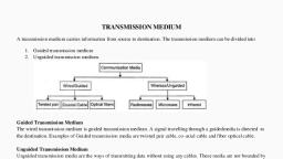
TRANSMISSION MEDIA, Transmission media is a means by which a communication signal is carried from one system to another , A transmission medium can be defined as anything that can carry information from a source to a destination. , The transmission medium is usually free space, metallic cable or fiber – optic cable., By Shrikant Hiremath
Page 140 :
GUIDED MEDIA, Guided Transmission Media uses a "cabling" system (or some sort of conductor) that guides the data signals along a specific path. , The data signals are bound by the "cabling" system., Guided Media is also known as Bound Media. , The conductor directs the signal propagating down it., Only devices physically connected to the medium can receive signals propagating down a guided transmission medium. , Types: , 1. Twisted-Pair Cable , 2. Coaxial Cable , 3. Fiber-OpticCable, By Shrikant Hiremath
Page 141 :
Twisted-pair cable , A twisted-pair consists of two copper wires twisted like a DNA helical structure. , Both the copper wires are insulated with plastic covers. , Usually, a number of such pairs are combined together and covered with a protective outer wrapping., Each of the twisted pairs act as a single communication link. , The use of twisted configuration minimises the effect of electrical interference from similar pairs close by., Twisted pairs are less expensive and most commonly used in telephone lines and LANs. , These cables are of two types: , Unshielded twisted-pair (UTP) , Shielded twisted-pair (STP), By Shrikant Hiremath
Page 143 :
Co-Axial Cable , Coaxial cable is another type of data transmission�medium. , It is better shielded and has more bandwidth than a twisted pair. , it has a copper wire at the core of the cable which is surrounded with insulating material. , The insulator is further surrounded with an outer conductor (usually a copper mesh). , This outer conductor is wrapped in a plastic cover. , The key to success of coaxial cable is its shielded design that allows the cable's copper core to transmit data quickly, without interference of environmental factors., These types of cables are used to carry signals of higher frequencies to a longer distance., By Shrikant Hiremath
Page 145 :
Fiber Optic Cable , The optical fiber cable carries data as light, which travels inside a thin fiber of glass ., Optic fiber uses refraction to direct the light through the media. , A thin transparent strand of glass at the centre is covered with a layer of less dense glass called cladding. , This whole arrangement is covered with an outer jacket made of PVC or Teflon. , Such types of cables are usually used in backbone networks. , These cables are of light weight and have higher bandwidth which means higher data transfer rate. , Signals can travel longer distances and electromagnetic noise cannot affect the cable. , However, optic fibers are expensive and unidirectional. Two cables are required for full duplex communication, By Shrikant Hiremath
Page 147 :
UNGUIDED (WIRELESS) TRANSMISSION MEDIUM, Unguided media transport data without using a physical conductor. This type of communication is often referred to as wireless communication. , It uses wireless electromagnetic signals to send data. , There are three types of Unguided Media , 1. Radio waves , 2. Micro waves , 3. Infrared., By Shrikant Hiremath
Page 149 :
Switching Techniques, What is Switching?, In large networks, there may be more than one paths for transmitting data from sender to receiver. Selecting a path that data must take out of the available options is called switching., By Shrikant Hiremath
Page 150 :
Types of Switching Techniques, 1) Circuit Switching�2) Packet Switching�3) Message Switching, By Shrikant Hiremath
Page 151 :
Circuit Switching, Circuit switching is a switching technique that establishes a dedicated path between sender and receiver., A complete end-to-end path must exist before the communication takes place., In case of circuit switching technique, when any user wants to send the data a request signal is sent to the receiver then the receiver sends back the acknowledgment to ensure the availability of the dedicated path. , After receiving the acknowledgment, dedicated path transfers the data., By Shrikant Hiremath
Page 152 :
Communication through circuit switching has 3 phases:, Circuit establishment, Data transfer, Circuit Disconnect, By Shrikant Hiremath
Page 154 :
Advantages Of Circuit Switching:, In the case of Circuit Switching technique, the communication channel is dedicated., It has fixed bandwidth., , Disadvantages Of Circuit Switching:, Once the dedicated path is established, the only delay occurs in the speed of data transmission., It takes a long time to establish a connection approx 10 seconds during which no data can be transmitted., It is more expensive than other switching techniques as a dedicated path is required for each connection., It is inefficient to use because once the path is established and no data is transferred, then the capacity of the path is wasted., In this case, the connection is dedicated therefore no other data can be transferred even if the channel is free., By Shrikant Hiremath
Page 155 :
Message Switching, Message Switching is a switching technique in which a message is transferred as a complete unit and routed through intermediate nodes at which it is stored and forwarded., In Message Switching technique, there is no establishment of a dedicated path between the sender and receiver., The destination address is appended to the message. Message Switching provides a dynamic routing as the message is routed through the intermediate nodes based on the information available in the message., Message switches are programmed in such a way so that they can provide the most efficient routes., Each and every node stores the entire message and then forward it to the next node. This type of network is known as store and forward network., Message switching treats each message as an independent entity., By Shrikant Hiremath
Page 156 :
Communication through message switching has 2 phases:, Store and forward , Message delivery, By Shrikant Hiremath
Page 158 :
Advantages Of Message Switching, Data channels are shared among the communicating devices that improve the efficiency of using available bandwidth., Traffic congestion can be reduced because the message is temporarily stored in the nodes., Message priority can be used to manage the network., The size of the message which is sent over the network can be varied. Therefore, it supports the data of unlimited size., Disadvantages Of Message Switching, The message switches must be equipped with sufficient storage to enable them to store the messages until the message is forwarded., The Long delay can occur due to the storing and forwarding facility provided by the message switching technique., By Shrikant Hiremath
Page 159 :
Packet Switching, The packet switching is a switching technique in which the message is sent in one go, but it is divided into smaller pieces, and they are sent individually., The message splits into smaller pieces known as packets and packets are given a unique number to identify their order at the receiving end., Every packet contains some information in its headers such as source address, destination address and sequence number., Packets will travel across the network, taking the shortest path as possible., All the packets are reassembled at the receiving end in correct order., If any packet is missing or corrupted, then the message will be sent to resend the message., If the correct order of the packets is reached, then the acknowledgment message will be sent., By Shrikant Hiremath
Page 161 :
Advantages Of Packet Switching:, Cost-effective: In packet switching technique, switching devices do not require massive secondary storage to store the packets, so cost is minimized to some extent. Therefore, we can say that the packet switching technique is a cost-effective technique., Reliable: If any node is busy, then the packets can be rerouted. This ensures that the Packet Switching technique provides reliable communication., Efficient: Packet Switching is an efficient technique. It does not require any established path prior to the transmission, and many users can use the same communication channel simultaneously, hence makes use of available bandwidth very efficiently., Disadvantages Of Packet Switching:, Packet Switching technique cannot be implemented in those applications that require low delay and high-quality services., The protocols used in a packet switching technique are very complex and requires high implementation cost., If the network is overloaded or corrupted, then it requires retransmission of lost packets. It can also lead to the loss of critical information if errors are nor recovered., By Shrikant Hiremath
Page 163 :
Connection-oriented Packet Switching (Virtual Circuit path), Before starting the transmission, it establishes a logical path or virtual connection between sender and receiver and all packets belongs to this flow will follow this predefined route., Call request and call accept packets are used to establish a connection between the sender and receiver., When a route is established, data will be transferred., After transmission of data, an acknowledgment signal is sent by the receiver that the message has been received., three phases takes place here- Setup, data transfer and tear down phase., By Shrikant Hiremath
Page 166 :
Unit-V�Using Telephone and Cable Networks for Data transmission�Error Detection and Correction, By Shrikant Hiremath
Page 167 :
Telephone Network, Telephone Network is used to provide voice communication. Telephone Network uses Circuit Switching. , Originally, the entire network was referred to as a plain old telephone system (POTS) which uses analog signals. With the advancement of technology, i.e. in the computer era, there comes a feature to carry data in addition to voice. , Today’s network is both analogous and digital., The Public Switched Telephone Network is understood as an aggregate of world’s circuit switched telephone networks, used for providing public telecommunication. , The PSTN networks are called POTS (Plain Old Telephone Systems). These networks are operated regionally, locally, nationally and inter-nationally using telephone lines, fiber optic cables, microwave transmission links or cellular communications., PSTN consists of switches at centralized points on the network, which act as nodes for communication between any point and any other point on the network. , All the types of Switching techniques discussed previously, such as circuit switching, packet switching and message switching are different modes of using PSTN., By Shrikant Hiremath
Page 168 :
Cellular network is an underlying technology for mobile phones, personal communication systems, wireless networking etc. The technology is developed for mobile radio telephone to replace high power transmitter/receiver systems. Cellular networks use lower power, shorter range and more transmitters for data transmission., By Shrikant Hiremath
Page 169 :
Features of Cellular Systems, Wireless Cellular Systems solves the problem of spectral congestion and increases user capacity. The features of cellular systems are as follows −, Offer very high capacity in a limited spectrum., Reuse of radio channel in different cells., Enable a fixed number of channels to serve an arbitrarily large number of users by reusing the channel throughout the coverage region., Communication is always between mobile and base station (not directly between mobiles)., Each cellular base station is allocated a group of radio channels within a small geographic area called a cell., Neighboring cells are assigned different channel groups., By limiting the coverage area to within the boundary of the cell, the channel groups may be reused to cover different cells., Keep interference levels within tolerable limits., Frequency reuse or frequency planning., Organization of Wireless Cellular Network., Cellular network is organized into multiple low power transmitters each 100w or less., By Shrikant Hiremath
Page 170 :
Peer-to-Peer Protocols, In Computer Networking, P2P is a file sharing technology, allowing the users to access mainly the multimedia files like videos, music, e-books, games etc. The individual users in this network are referred to as peers. The peers request for the files from other peers by establishing TCP or UDP connections., By Shrikant Hiremath
Page 171 :
How P2P works, A peer-to-peer network allows computer hardware and software to communicate without the need for a server. Unlike client-server architecture, there is no central server for processing requests in a P2P architecture. The peers directly interact with one another without the requirement of a central server. , Now, when one peer makes a request, it is possible that multiple peers have the copy of that requested object. Now the problem is how to get the IP addresses of all those peers. This is decided by the underlying architecture supported by the P2P systems. By means of one of these methods, the client peer can get to know about all the peers which have the requested object/file and the file transfer takes place directly between these two peers., By Shrikant Hiremath
Page 176 :
Automatic Repeat reQuest (ARQ), Automatic Repeat ReQuest (ARQ) is a group of error – control protocols for transmission of data over noisy or unreliable communication network. These protocols reside in the Data Link Layer and in the Transport Layer of the OSI (Open Systems Interconnection) reference model. They are named so because they provide for automatic retransmission of frames that are corrupted or lost during transmission. ARQ is also called Positive Acknowledgement with Retransmission (PAR)., ARQs are used to provide reliable transmissions over unreliable upper layer services. They are often used in Global System for Mobile (GSM) communication., By Shrikant Hiremath
Page 177 :
Working Principle, In these protocols, the receiver sends an acknowledgement message back to the sender if it receives a frame correctly. If the sender does not receive the acknowledgement of a transmitted frame before a specified period of time, i.e. a timeout occurs, the sender understands that the frame has been corrupted or lost during transit. So, the sender retransmits the frame. This process is repeated until the correct frame is transmitted., By Shrikant Hiremath
Page 178 :
Types of ARQ Protocols, Stop – and – Wait ARQ − Stop – and – wait ARQ provides unidirectional data transmission with flow control and error control mechanisms, appropriate for noisy channels. The sender keeps a copy of the sent frame. It then waits for a finite time to receive a positive acknowledgement from receiver. If the timer expires, the frame is retransmitted. If a positive acknowledgement is received then the next frame is sent., By Shrikant Hiremath
Page 179 :
Go – Back – N ARQ − Go – Back – N ARQ provides for sending multiple frames before receiving the acknowledgement for the first frame. It uses the concept of sliding window, and so is also called sliding window protocol. The frames are sequentially numbered and a finite number of frames are sent. If the acknowledgement of a frame is not received within the time period, all frames starting from that frame are retransmitted., By Shrikant Hiremath
Page 180 :
Selective Repeat ARQ − This protocol also provides for sending multiple frames before receiving the acknowledgement for the first frame. However, here only the erroneous or lost frames are retransmitted, while the good frames are received and buffered., By Shrikant Hiremath
Page 181 :
High-level Data Link Control (HDLC), High-level Data Link Control (HDLC) is a group of communication protocols of the data link layer for transmitting data between network points or nodes. , Since it is a data link protocol, data is organized into frames. , A frame is transmitted via the network to the destination that verifies its successful arrival., It is a bit - oriented protocol that is applicable for both point - to - point and multipoint communications., By Shrikant Hiremath
Page 182 :
Transfer Modes, HDLC supports two types of transfer modes, normal response mode and asynchronous balanced mode., Normal Response Mode (NRM) − Here, two types of stations are there, a primary station that send commands and secondary station that can respond to received commands. It is used for both point - to - point and multipoint communications., By Shrikant Hiremath
Page 184 :
Asynchronous Balanced Mode (ABM) − Here, the configuration is balanced, i.e. each station can both send commands and respond to commands. It is used for only point - to - point communications., By Shrikant Hiremath
Page 185 :
HDLC Frame, HDLC is a bit - oriented protocol where each frame contains up to six fields. The structure varies according to the type of frame. The fields of a HDLC frame are −, Flag − It is an 8-bit sequence that marks the beginning and the end of the frame. The bit pattern of the flag is 01111110., Address − It contains the address of the receiver. If the frame is sent by the primary station, it contains the address(es) of the secondary station(s). If it is sent by the secondary station, it contains the address of the primary station. The address field may be from 1 byte to several bytes., Control − It is 1 or 2 bytes containing flow and error control information., Payload − This carries the data from the network layer. Its length may vary from one network to another., FCS − It is a 2 byte or 4 bytes frame check sequence for error detection. The standard code used is CRC (cyclic redundancy code), By Shrikant Hiremath
Page 187 :
Point-to-Point Protocol (PPP), Point - to - Point Protocol (PPP) is a communication protocol of the data link layer that is used to transmit multiprotocol data between two directly connected (point-to-point) computers. , It is a byte - oriented protocol that is widely used in broadband communications having heavy loads and high speeds. , Since it is a data link layer protocol, data is transmitted in frames., By Shrikant Hiremath
Page 188 :
Services provided by PPP, It defines the format of frames through which the transmission occurs., It defines the link establishment process. If user establishes a link with a server, then "how this link establishes" is done by the PPP protocol., It defines data exchange process, i.e., how data will be exchanged, the rate of the exchange., The main feature of the PPP protocol is the encapsulation. It defines how network layer data and information in the payload are encapsulated in the data link frame., It defines the authentication process between the two devices. The authentication between the two devices, handshaking and how the password will be exchanged between two devices are decided by the PPP protocol., By Shrikant Hiremath
Page 189 :
Services Not provided by the PPP protocol, It does not support flow control mechanism., It has a very simple error control mechanism., As PPP provides point-to-point communication, so it lacks addressing mechanism to handle frames in multipoint configuration., By Shrikant Hiremath
Page 190 :
Frame format of PPP protocol, Flag: The flag field is used to indicate the start and end of the frame. The flag field is a 1-byte field that appears at the beginning and the ending of the frame. The pattern of the flag is similar to the bit pattern in HDLC, i.e., 01111110., Address: It is a 1-byte field that contains the constant value which is 11111111. These 8 ones represent a broadcast message., Control: It is a 1-byte field which is set through the constant value, i.e., 11000000. It is not a required field as PPP does not support the flow control and a very limited error control mechanism. The control field is a mandatory field where protocol supports flow and error control mechanism., Protocol: It is a 1 or 2 bytes field that defines what is to be carried in the data field. The data can be a user data or other information., Payload: The payload field carries either user data or other information. The maximum length of the payload field is 1500 bytes., Checksum: It is a 16-bit field which is generally used for error detection., By Shrikant Hiremath
Page 192 :
ERRORS, DETECTION & CORRECTION, Errors in the data are basically caused due to the various impairments that occur during the process of transmission. , When there is an imperfect medium or environment exists in the transmission it prone to errors in the original data. , Errors can be classified as follows: , Attenuation , Noise , Distortion, By Shrikant Hiremath
Page 193 :
Attenuation: As signal travels through the medium, its strength decreases as distance increases, the example is voice, it becomes weak over the distance and loses its contents beyond a certain distance. As the distance increases attenuation also increases. , Noise: Noise is defined as an unwanted data. When some electromagnetic signal gets inserted during the transmission, it is generally called as a Noise. Due to Noise it is difficult to retrieve the original data or information. , Distortion: When there is an interference of the different frequencies who travel across the medium with the different speed, Distortion occurs. So it is important to have a space (guard space) between the different frequencies., By Shrikant Hiremath
Page 194 :
TYPES OF ERRORS, Single-bit errors: In single-bit error, a bit value of 0 changes to bit value 1 or vice versa., By Shrikant Hiremath
Page 195 :
Burst errors: In Burst error, multiple bits of the binary value changes. Burst error can change any two or more bits in a transmission. These bits need not be adjacent bits., By Shrikant Hiremath
Page 196 :
REDUNDANCY, In order to detect and correct the errors in the data communication we add some extra bits to the original data. , These extra bits are nothing but the redundant bits which will be removed by the receiver after receiving the data., Their presence allows the receiver to detect or correct corrupted bits. , Instead of repeating the entire data stream, a short group of bits may be attached to the entire data stream. This technique is called redundancy because the extra bits are redundant to the information., they are discarded as soon as the accuracy of the transmission has been determined., By Shrikant Hiremath
Page 197 :
Error Detection Methods, Simple Parity check, Blocks of data from the source are subjected to a check bit or parity bit generator form, , where a parity of :, 1 is added to the block if it contains odd number of 1’s, and, 0 is added if it contains even number of 1’s, This scheme makes the total number of 1’s even, that is why it is called even parity checking., By Shrikant Hiremath
Page 199 :
Cyclic Redundancy Check (CRC), CRC is a different approach to detect if the received frame contains valid data. , This technique involves binary division of the data bits being sent. , The divisor is generated using polynomials. The sender performs a division operation on the bits being sent and calculates the remainder. , Before sending the actual bits, the sender adds the remainder at the end of the actual bits. , Actual data bits plus the remainder is called a codeword. , The sender transmits data bits as codewords., At the other end, the receiver performs division operation on codewords using the same CRC divisor. , If the remainder contains all zeros the data bits are accepted, otherwise it is considered as there some data corruption occurred in transit., By Shrikant Hiremath
Page 201 :
Checksum, In checksum error detection scheme, the data is divided into k segments each of m bits., In the sender’s end the segments are added using 1’s complement arithmetic to get the sum. The sum is complemented to get the checksum., The checksum segment is sent along with the data segments., At the receiver’s end, all received segments are added using 1’s complement arithmetic to get the sum. The sum is complemented., If the result is zero, the received data is accepted otherwise discarded., By Shrikant Hiremath
Page 203 :
Synchronous optical networking (SONET), Synchronous optical networking (SONET) is a standardized digital communication protocol that synchronously transfers multiple data streams over long distances through fiber optic cables. , It is a physical layer specification that allows simultaneous transmission of voice, data, and video at speeds as high as 1Gbps through a single fiber. , In telephone networks, it is used for transmission of a huge amount of telephone calls and data streams through fiber., SONET was standardized by the American National Standards Institute (ANSI)., By Shrikant Hiremath