Page 1 :
2021:BASIC MECHANICAL ENGINEERING, MODULE 1, RISHAD A R, , Lecturer GPTC PALAKKAD, , Dept. of Mechanical Engineering, , 1
Page 2 :
Engineering materials, • Engineering materials refers to the group, of materials that are used in the, construction of manmade structures and, components., • The primary function of an engineering, material is to withstand applied loading, without breaking and without exhibiting, excessive deflection., • The major classifications of engineering, materials include metals, polymers,, ceramics, and composites., , Dept. of Mechanical Engineering, , 2
Page 3 :
Mechanical properties of materials, • STRENGTH - The strength of a material is its capacity to withstand destruction, under the action of external loads. The stronger the material the greater the load, it can withstand. It therefore determines the ability of a material to withstand, stress without failure., • ELASTICITY - Elasticity is that property of a material by virtue of which, deformation caused by applied load disappears upon removal of the load. In, other words, elasticity of a material is its power of coming back to its original, position after deformation when the stress or load is removed., • PLASTICITY - The plasticity of a material is its ability to undergo some degree, of permanent deformation without rupture or failure., , Dept. of Mechanical Engineering, , 3
Page 4 :
• STIFFNESS – The resistance of a material to elastic deformation or deflection, deformation., • HARDNESS – resistance of a material to wear, scratching etc., • TOUGHNESS – resist fracture due to impact load., • DUCTILITY - Ductility is that property of a material which enables it to draw out, into thin wire. Mild steel is a ductile material., • MALLEABILITY – Malleability of a material is its ability to be flattened into, thin sheets without cracking by hot or cold working. Aluminium, copper, tin,, lead, steel, etc. are some malleable metals., • RESILIENCE - Resilience is the capacity of a material to absorb energy, elastically. On removal of the load, the energy stored is given off exactly as in, spring when the load is removed., • CREEP – Creep is a phenomenon of slow plastic deformation at high, temperature under a constant load as the function of time., Dept. of Mechanical Engineering, , 4
Page 5 :
• FATIGUE - The fatigue properties of a material determine its behaviour when, subjected to thousands or even millions of cyclic load applications in which the, maximum stress developed in each cycle is well within the elastic range of the, material., • CREEP - The slow and progressive deformation of a material with time at, constant stress is called creep., • BRITTLENESS - It is the property of breaking of a material with little, permanent distortion. Eg : Cast Iron, , Dept. of Mechanical Engineering, , 5
Page 6 :
Physical properties of materials, Colour, Finish, Density- mass per unit volume, Viscosity - offers resistance to shear force, Porosity- Porosity is the quality of being porous, or full of tiny holes. Liquids go, right through things that have porosity., • Specific gravity- The ratio of the density of the fluid to the density of water, (1000 kg/m3 at a standard condition) is defined as Specific Gravity or Relative, Density of fluids., • Fusibility- Fusibility is the quality of objects of being fusible or convertible to, liquid by applying heat., •, •, •, •, •, , Dept. of Mechanical Engineering, , 6
Page 7 :
Thermal properties of materials, • Specific heat - The specific heat of a substance is the amount of heat required to, change the temperature of unit mass of substance by one degree., • Thermal conductivity - The rate at which heat can flow through a material, under the influence of a given temperature gradient is known as thermal, conductivity., • Thermal resistance - The ability of a material to withstand high temperature is, known as thermal resistance., • Thermal diffusivity - defined as the ratio between the thermal conductivity, and heat required per unit volume., , Dept. of Mechanical Engineering, , 7
Page 8 :
Electrical properties of materials, • Resistance - is defined as the property of a substance due to which it opposes, the flow of electricity (i.e., electrons) through it., • Resistivity – resistivity of a material may be defined as the resistance offered by, unit cross section of a material of unit length, • Conductance - Conductance is defined as the property of a substance due to, which it allows the flow of electricity, • Conductivity - Conductance of a material per unit volume of material is known, as conductivity., • Capacitance - A capacitor consists of two conducting surfaces separated by a, layer of an insulating medium called dielectric. The purpose of a capacitor is to, store electrical energy by electrostatic stress in the dielectric. The property of a, capacitor to store electricity is called its capacitance., Dept. of Mechanical Engineering, , 8
Page 9 :
Chemical properties of materials, • Corrosion resistance - It is the resistance of a metallic material to destruction, caused by chemical or electrochemical reaction, • Acidity - Acidity is the property of a substance that contain hydrogen , which, when react with a metal to form a salt., • Alkalinity - is the property of the substance, which when react with acids form, salt., , Dept. of Mechanical Engineering, , 9
Page 10 :
Testing of materials, • Testing is for the purpose of providing an engineer with the necessary data for, his design calculations and determining whether a material, either in the raw or, fabricated form, meets specifications., • Destructive testing uses various types of mechanical tests such as tensile,, compressive, hardness, impact, fatigue and creep testing., • Non-destructive testing on the other hand, includes visual examination,, radiographic, ultrasonic, liquid penetrant and magnetic particle testing., , Dept. of Mechanical Engineering, , 10
Page 11 :
Destructive Testing of materials, • Tensile test is a very commonly used, test,, performed to determine different tensile properties, such, as, tensile, strength,, yield, point,, proportionality limit, elasticity limit, elongation,, breaking strength etc.., • A gradually increasing tensile load is applied along, the axis of the specimen., • The corresponding elongation of the gauge length is, measured with the help of a strain gauge or an, extensometer and the values are recorded., • The load is slowly increased until the specimen, finally breaks passing through different stages of, deformation., Dept. of Mechanical Engineering, , Tensile test specimen, , 11
Page 12 :
• Compression tests are used to determine the material, behaviour under a load. The maximum stress a material, can sustain over a period under a load (constant or, progressive) is determined., • Brinell Hardness Test – It is a ball indentation method, and a hardened steel ball of 10 mm in diameter is used as, indenter. The loading force is in the range of 300N to, 30000N., • Rockwell Hardness Test – In the rockwell hardness test, the depth of the indenter penetration into the specimen, surface is measured. The loading force is in the range of, 1000N to 1500N., • Vicker’s Hardness Test – The Vicker’s indenter is a, square based diamond pyramid. The load varying from, 10N to 1200N is usually applied for 30 sec., , Brinell Hardness Test, , Vicker’s hardness Test, Dept. of Mechanical Engineering, , 12
Page 13 :
• Impact test – it is used for measuring the toughness of, materials and their capacity of resisting impact load. In this, test the pendulum is swing up to its starting position and, then it is allowed to strike the notched specimen, fixed in a, vice. The pendulum fractures the specimen., • Fatigue test – Fatigue is a type of failure, which takes place, when the material subjected to alternating loads. The fatigue, test determines the stresses which a sample of material of, standard dimensions, can safely endure for a given number, of cycles., • Creep Test – Creep testing is conducted using a tensile, specimen to which a constant stress is applied at a constant, temperature, often by the simple method of suspending, weights from it. The test is recorded on a graph of strain, versus time., , Fatigue Test, , Creep Test, Dept. of Mechanical Engineering, , 13
Page 14 :
Creep curve, • Upon application of the load there is an instantaneous elastic, deformation. The creep curve consists of three region, Primary creep, • This occurs first and this region has a continuously decreasing, creep rate. That is, the slope of the curve reduces with time due to, an increase in creep resistance or strain hardening, Secondary creep, • This region has a constant creep rate. That is, the creep curve, becomes linear. This is the stage of creep that is of the longest, duration., Tertiary creep, • In this region there is an acceleration of the creep rate and, ultimate failure. This failure is frequently termed rupture, Dept. of Mechanical Engineering, , 14
Page 15 :
Non-destructive testing, • Non destructive testing (NDT) is the process of, inspecting, testing, or evaluating materials,, components or assemblies for discontinuities,, or differences in characteristics without, destroying the serviceability of the part or, system. In other words, when the inspection or, test is completed the part can still be used., • The most common methods of non-destructive, testing are:, • Liquid Penetrant Test (LPT), • Radiographic Test (RT), • Ultrasonic Testing (UT), Dept. of Mechanical Engineering, , 15
Page 16 :
• Liquid penetrant testing, ❖ Invisible cracks, porosity and other defects on, the surface of components easily detected by, this technique., ❖ Components may be ferrous, nonferrous,, plastic, glass or ceramic., ❖ Procedure –, 1. Cleaning of surface.(Grease, oil, any other, material)., 2. Drying of surface., 3. Applying dye-penetrant on clean and dry surface., It is allowed to penetrate in surface flaws, Dept. of Mechanical Engineering, , 16
Page 17 :
4. Removing excess penetrant by soft or clean cotton., 5. Applying developer on surface. This pulls out dye from flaws and flaws are, revealed by colour of dye. Instead of developer, fine developing powder or talc, powder can be sprinkled on the surface., Advantages of Dye Penetrant testing, ❖ This test can be applied to almost any type of metals, non metals, magnetic or, non magnetic type., ❖ Simple to utilize and control., ❖ Results of test can be interpreted fastly., ❖ Cost of test is very less as it does not require any instrument or electronic, display units, ❖ Sensitivity is greater than that of magnetic particle testing., , Dept. of Mechanical Engineering, , 17
Page 18 :
• Radiography Test, ❖ NDT method that utilizes x-rays or gamma, radiation to detect discontinuities in, materials, and to present their images on, recording medium., ❖ This includes X-rays, gamma rays and radioisotopes. This method is used to check, internal cracks, defects in materials which are, made by casting, welding, forging., , Dept. of Mechanical Engineering, , 18
Page 19 :
❖ Nowadays, radiography techniques are finding more extensive, applications in the field of physical metallurgy and in the treatment of, various diseases., ❖ Rays are absorbed by the materials through which they are passed in the, proportion of their density. The rays, after passing through the, components, show a picture on a fluorescent screen or on a photographic, plate., ❖ The cracks, blow holes and cavities appear lighter, whereas inclusions of, impurities appear darker than the metal component., ❖ Developed photographic film show lighter and darker areas to represent, the radiograph of defects in the component., , Dept. of Mechanical Engineering, , 19
Page 20 :
• Ultrasonic testing, ❖ Principle1. Measure of time required by ultrasonic, vibrations to penetrate material of interest ,, reflect from opposite side or from internal, discontinuity and return to point from, where first introduced., 2. Behaviour of waves through cycle with, regard to time is recorded on CRO screen., 3. By observing this presence of defect and, their location can be detected., , Dept. of Mechanical Engineering, , 20
Page 21 :
Advantages of Ultrasonic Test, ❖ Better detection of flaws situated deep in metal due to superior penetrating, power of ultrasonic waves, ❖ High sensitivity, better accuracy and reliability, ❖ The equipment is portable and easy to handle, ❖ Output of test can be processed by computer which lead to improved result, reliability, Applications of Ultrasonic Test, ❖ Inspection of large castings and forging, for internal soundness, before carrying, out expensive machining operations, ❖ Inspection of moving strip or plate, ❖ Routine inspection of locomotive axles and wheel pins for fatigue cracks, , Dept. of Mechanical Engineering, , 21
Page 22 :
Stress Strain diagram for ductile material-Mild steel, i) Proportional Limit: It is the region in the strain, curve which obeys Hooke’s law i.e. within elastic, limit the stress is directly proportional to the strain, produced in the material. In this limit the ratio of, stress with strain gives us proportionality constant, known as young’s modulus. The point OA in the, graph is called the proportional limit., ii) Elastic Limit: It is the point in the graph up to, which the material returns to its original position, when the load acting on it is completely removed., Beyond this limit the material cannot return to its, original position and a plastic deformation starts to, appear in it. The point A is the Elastic limit in the, Dept. of Mechanical Engineering, graph., , 22
Page 23 :
iii)Yield Point or Yield Stress Point: Yield point in a stress strain diagram is, defined as the point at which the material starts to deform plastically. After the, yield point is passed there is permanent deformation develops in the material, and which is not reversible. There are two yield points and it is upper yield, point and lower yield point. The stress corresponding to the yield point is called, yield point stress. The point B is the upper yield stress point and C is the lower, yield stress point., (iv)Ultimate Stress Point: It is the point corresponding to the maximum stress, that a material can handle before failure. It is the maximum strength point of the, material that can handle the maximum load. Beyond this point the failure takes, place. Point D in the graph is the ultimate stress point., (v)Fracture or Breaking Point: It is the point in the stress strain curve at which, the failure of the material takes place. The fracture or breaking of material takes, place at this point. The point E is the breaking point in the graph., Dept. of Mechanical Engineering, , 23
Page 24 :
Stress Strain diagram for brittle material- Cast iron, • For brittle materials, there is no difference, between the ultimate strength and the, breaking strength., • There is no necking of the specimen in the, case of a brittle material, and rupture occurs, along a surface perpendicular to the load., • Common brittle materials include cast iron,, glass, and stone, , Dept. of Mechanical Engineering, , 24
Page 25 :
BLAST FURNACE – To manufacture Pig Iron, • A blast furnace is a refractory-lined steel, chamber with a diameter of about 9 to 11 m, at its widest and a height of 40 m. The blast, furnace consists of the following regions, • Stack - charge is completely solid, charge, get heated from 200°C to 1200°C at the end, of the stack region., • Bosh – charge start to soften and get fuse, except coke, slag starts forming, • Tuyer zone - combustion of coke occurs,, entire charge is in molten state., • Hearth - smallest cross section of the, furnace, slag is removed through slag holes, Dept. of Mechanical Engineering, , 25
Page 26 :
• A blast furnace is a refractory-lined steel chamber with a diameter of about 9 to, 11 m at its widest and a height of 40 m. The blast furnace consists of the, following regions, • Stack - charge is completely solid, charge get heated from 200°C to 1200°C at, the end of the stack region., • Bosh – charge start to soften and get fuse except coke, slag starts forming, • Tuyer zone - combustion of coke occurs, entire charge is in molten state., • Hearth - smallest cross section of the furnace, slag is removed through slag, holes, , Dept. of Mechanical Engineering, , 26
Page 27 :
• Burning of coke produces CO gas and it has a reducing effect on the iron ore. The, reaction can be written as follows (using hematite as the starting ore), Fe2O3+ CO ⟹ 2FeO + CO2, • Carbon dioxide reacts with coke to form more carbon monoxide, CO2+ C (coke) ⟹2CO, FeO + CO ⟹ Fe +CO2, • The lime combines with impurities such as silica (SiO2), sulphur (S), and, alumina (Al2O3) in reactions that produce a molten slag that floats on top of the, iron., • The molten iron is collected at the base of the blast furnace, Dept. of Mechanical Engineering, , 27
Page 28 :
Cupola furnace –To manufacture Cast Iron, • Cupola furnace is a refractory-lined steel cylinder with a diameter of about 2m and, a height of 12 m. It consists of the following regions., • Well, Space between the bottom of the tuyers and the sand bed, Molten metal is get collected in this portion before tapping out, , • Combustion zone, Also called as oxidizing zone., Located at the upper of the tuyers to a 15 cm. to 30 cm above, Combustion takes place in this zone to have a temperature of 1540°C to 1870°C, Few exothermic reactions take place in this zone these are represented as:, C + O2 ⟹ CO2 + Heat, Si + O2 ⟹ SiO2 + Heat, 2Mn + O2 ⟹ 2MnO + Heat, Dept. of Mechanical Engineering, , 28
Page 29 :
• Reducing zone, Also known as the protective zone, Located above combustion zone In this zone, CO2 is changed to CO through an endothermic reaction by decreasing, temperature, CO2 + C (coke) ⟹ 2CO – Heat, , • Melting zone, It is the lower layer of metal charge above coke bed, The metal charge starts melting in this zone, represented by the chemical reaction given as under., 3Fe + 2CO ⟹ Fe3C + CO2, , Dept. of Mechanical Engineering, , 29
Page 30 :
• Preheating zone, Located between upper end of the melting zone, to the bottom of the charging door contains a, number of alternate layers of coke bed, flux and, metal charge. The main objective is to preheat, the charges from room temperature to about, 1090°C, • Stack, Portion above the preheating zone, Provides the passage to hot gases to go, atmosphere from furnace, , Dept. of Mechanical Engineering, , 30
Page 31 :
STEEL, • Alloy of iron and carbon with carbon content maximum up to 2%, • Carbon occurs in the form of iron carbide, which increases the hardness and, strength, • The steel may be classified into following types, • Plain carbon steel, • Alloy Steel, , Dept. of Mechanical Engineering, , 31
Page 32 :
PLAIN CARBON STEEL, • Contains carbon from 0.06to 1.5%, • Mild steel – 0.15% C, • Low-carbon–contains 0.15-0.43%C –used for machine components, that do not require high strength, • Medium-carbon steel–contains 0.43-0.8%C –used in applications, requiring higher strength than is available in low carbon steels also, used for making automotive and agricultural equipment parts, • High-carbon steel–contains 0.83-1.5%C –used for applications, requiring strength, hardness, and wear resistance also used for, making cutting tools, cable, music wire, springs etc, Dept. of Mechanical Engineering, , 32
Page 33 :
ALLOY STEEL, • Stainless steel - contains chromium and nickel as alloy and rest is iron–, resists oxidation and corrosion. A steel containing 18% chromium and 8%, nickel is referred to as 18/8 steel., • Cr- Anti corrosive application, hardness, • Ni – Hardenability, machinability, • High speed steel - It is basically high-carbon steel (0.75 – 1.5% C) containing, large amounts of alloying elements. The principal alloying elements used in this, steel are tungsten, chromium, molybdenum, vanadium and cobalt., • Magnetic Steel - This kind of steel is rich in cobalt and tungsten. Typical, magnetic steel contains 15-40% cobalt, 0.5-10% tungsten, 1.5-9% chromium, and up to 1% carbon.It is mainly used for permanent magnets, loud speakers,, magnetos, electrical measuring instruments, etc, Dept. of Mechanical Engineering, , 33
Page 34 :
CAST IRON, •, •, •, •, •, •, •, •, , Cast iron contents, Iron ,carbon -1.7% to 6.67%, phosphorus ,silicon, sulphur, manganese, Cast iron is very brittle and weak in tension, It has high compressive strength, high wear resistance and good machinability, CLASSIFICATION OF CAST IRON, Grey cast iron - contains about 2.5 to 3.8% carbon in free form (graphite form), White cast iron - contains 3.2 to 3.6% carbon in the combined form (cementite), Ductile cast iron - contains 3.2 to 4.2% carbon in graphite form, , Dept. of Mechanical Engineering, , 34
Page 35 :
NON-FERROUS METALS, • Contain a metal other than iron as their chief constituent, • Copper- A soft, malleable and ductile material with a reddish-brown, appearance used in making electric cables., • Copper Alloys – Brass, Bronze, Gun Metal, • Nickel - Have high mechanical strength properties, corrosion resistance etc, • Nickel Alloys - Monel metal, Inconel, Nichrome, Nimonic, • Lead – preparing solders, used in car batteries, resist many acids, • Lead Alloys – Babbit metal(white metal), • Aluminium – lightest, household heating appliances, it lack strength, • Aluminium alloys - Duralumin, Y-alloy, Magnalium, Hindalium, Dept. of Mechanical Engineering, , 35
Page 36 :
Alloys and their constituent, •, •, •, •, •, •, •, •, •, •, •, •, , Brass – Cu=60%, Zn=40%, Bronze – Cu=94%, Sn=6%, Gun Metal – Cu=88%, Sn=10%, Zn=2%, Monel metal – Ni=68%, Cu=29%, Fe,Mn,Si,C=3%, Inconel – Ni=80%, Cr=14% Fe=6%, Nichrome – Ni=65%, Cr=15%, Fe=20%, Nimonic- Ni=80%, Cr=20%, Babbit Metal – Sn=90%, Cu=10%, Duralumin – Cu=4%, Mg=0.4-7%, Mn-0.4-7%, remaining Al(97%), Magnalium – Mg =2-10%, Cu=1.75% , remaining Al(88%), Y-alloy - Mg =3.5%, Cr=0.1-0.2% , remaining Al(96%), Hindalium - Cu=4%, Mg=01.2-1.7%, Ni-1.8-2.3%, remaining Al(97%), Dept. of Mechanical Engineering, , 36
Page 37 :
2021:BASIC MECHANICAL ENGINEERING, MODULE 2, RISHAD A R, , Lecturer GPTC PALAKKAD, , Dept. of Mechanical Engineering, , 1
Page 38 :
Steam, • Steam is the most common working substance employed as working medium in, steam engines, steam turbines and in atomic power plants for steam generation., • There occurs a change in the properties of steam during a process and that helps, to attain the desired effect., • Steam also finds application in process industries and also acts as heat carrying, agent in the heat exchange equipment, • Wet, Dry and Superheated Steam, • Depending on its properties, a steam may be saturated or superheated., • The steam is called saturated when the molecules escaping from the liquid, become equal to the molecules returning to it., • The temperature of saturated steam (vapour) and the liquid in contact with it is, called the saturation point or boiling point., Dept. of Mechanical Engineering, , 2
Page 39 :
• The liquid at its boiling point at a specified pressure is called saturated liquid, • Such a liquid is in equilibrium with its own vapour at specified, temperature/pressure, • At standard atmospheric pressure, the water boils at 100oC and generates its, own vapour, • Thus corresponding to standard atmospheric pressure, the water at 100oC is, a saturated liquid, • Saturated steam may be dry or wet, • When the saturated vapour contains particles of liquid evenly distributed, over the entire mass of vapour, it is called wet saturated steam, • Saturated liquid which contains no liquid particle is called dry saturated, steam, • Steam becomes superheated, if at a given pressure, its temperature is, higher than that of saturation temperature., , Dept. of Mechanical Engineering, , 3
Page 40 :
Steam Boilers, • A steam boiler or a steam generator is a device, used to create steam by applying heat energy to, water., • The heated or vaporized steam is taken out of the, boiler for use in various processes and heating, applications., • Thus, the boiler is a closed vessel made of highquality steel in which steam is generated from, water by transfer of heat produced by burning of, fuel., , Dept. of Mechanical Engineering, , 4
Page 41 :
Classification of Boilers, • On the basis of the content of the tube as, • Fire-tube boiler: The hot flue gases pass through the tubes and water surrounds the tube, from all sides. For example, Cochran boiler, Lancashire boiler., • Water-tube boiler: The water passes through the tubes and hot flue gases surround the, tube from all sides. For example, Babcock and Wilcox boiler, Lamount boiler., • According to axis of shell –horizontal, vertical or inclined, • According to position of furnace –internal and external, • According to water circulation –forced circulation and natural circulation, • According to pressure –high pressure and low pressure boiler, • According to use –marine and locomotive, • According to movement –portable and stationary, • According to number of tube –single tube and multi tube boiler, Dept. of Mechanical Engineering, , 5
Page 42 :
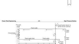
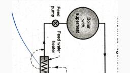
La-Mont boiler, • This boiler works on forced circulation and the circulation is, maintained by a centrifugal pump., ➢ Major components:, • Steam seperating drum – it is placed outside the boiler, assembly. The drum receives a mixture of steam and water, from the evaporator tubes and feeds water from the, economizer. The water particles in the steam are seperated, here, • Water circulating pump – The centrifugal pump is used to, draw the water from the drum through the down corner. The, pump circulates water by forced circulation and equal to 8 to, 10 times the weight of steam evaporates which prevent the, overheating of tubes., Dept. of Mechanical Engineering, , 6
Page 43 :
• Distributor head – It is used to control the flow of water to the evaporator, tubes., • Evaporator – it is used to evaporate the water into steam., • Convective superheater – the steam produced in the boiler is in the state of, saturated condition. The moisture in the steam will affect the turbine blades and, cause corrosion. To avoid this, the superheater is used . It is used to improve the, temperature of steam and to improve effeciency., • Economiser – The main purpose of economiser in the boiler is to preheat the, feedwater using the exhaust gases flowing out from the boiler to the, atmosphere., • Air preheater – it is used to preheat the air by using exhaust gases flowing out, from the boiler . The preheated air is supplied to the furnace for combustion., Dept. of Mechanical Engineering, , 7
Page 44 :
➢ Working – The feedwater passes through the economizer to the drum, from, which it is drawn to the circulating pump., ➢ The pump delivers the feed water to the tube evaporative section., ➢ The circulating of water is about 8 to 10 times the steam evaporated in the, boiler, ➢ The steam in the drum is a mixture of steam and water and the steam is drawn, through a convection superheater., ➢ The superheated steam is supplied to the prime mover through steam outlet., ➢ The working presssure of Lamount boiler is about 170 bar and capacity upto, 50,000kg of steam per hour at 500°C temperature., , Dept. of Mechanical Engineering, , 8
Page 45 :
Cochran boiler, • It is a multi-tubular, internally fired, fire-cube boiler., • It is an improvement over the simple vertical boiler as it, provides greater heating surface., • Figure shows the schematic diagram of a Cochran boiler., • Working- Flue Gases Path- The combustion of fuel and, air on the grate produces hot flue gases., • These gases enter through the short flue pipe into the, combustion chamber., • From The combustion chamber they find their path, through the horizontal fire tubes., • Finally, they enter the smoke box and get discharged to the, atmosphere through the chimney, Dept. of Mechanical Engineering, , 9
Page 46 :
• Water Circulation The water comes down by the cooler wall of the shell and, rises up past the fire tubes., • The hot gases passing through these tubes transfer their heat to water., • In doing so, water gets converted into steam, which gets accumulated in the, upper portion oldie shell from where it can be supplied to the user., • The sufficient gap between the fire tubes helps in accelerating the natural, convection currents., • The flow of flue gases and circulation of water inside the boiler are shown with, suitable arrows in the figure., • The superheater can be fitted in the combustion chamber if required, while an, economizer and an air preheater can be placed near smoke box to increase the, efficiency., , Dept. of Mechanical Engineering, , 10
Page 47 :
COMPARISON BETWEEN FIRE TUBE AND WATER, TUBE BOILER, Aspects, , Fire Tube, , Water Tube, , Position of water and hot gas, , Hot gas inside the tube and water Water inside the tube and hot gases, outside the tube, outside the tube, , Mode of firing, , Generally internal fired, , Generally externally fired, , Operating pressure, , Operating pressure limited to 16 bar, , Can work as high as 100 bar, , Rate of steam production, , Lower, , Higher, , Suitability, , Not suitable for large power plants, , Suitable for large power plants, , Risk on bursting, , Involves lesser risk on explosion due to Involves more risk on explosion due, lower pressure, to high pressure, , Construction, , Difficult, , Simple, , Transportation, , Difficult, , Simple, Dept. of Mechanical Engineering, , 11
Page 48 :
Boiler mountings, • These are the fittings and devices necessary, for the safety of the boiler and complete, control of the process of steam generation., ❖ The following mountings should be always, fitted to a boiler., • Steam stop valve, • Safety valve, • Water-Ievel indicator, • Pressure gauge, • Feed check valve, • Fusible plug, Dept. of Mechanical Engineering, , 12
Page 49 :
• Steam Stop Valve, • Function: The function of steam stop valve is to, regulate the flow of steam from boiler to steam pipe, connecting the engine., • Location: It is mounted on the highest portion of, the steam space of a boiler so that it can supply, steam of maximum possible quality, • Working: Under the normal working condition, the, valve is open and steam flows from the boiler to the, steam pipe., • For changing the flow rate of steam the valve may be, raised or lowered by rotating the hand wheel and, thereby the spindle., • When the steam is not at all required, the valve may, be lowered completely to shut off the supply of, steam., Dept. of Mechanical Engineering, , 13
Page 50 :
• Safety valve, • Function: The function of the safety valve is to, blow off the steam from the boiler to the, atmosphere when the pressure of the steam, inside the boiler exceeds the working pressure., • Location: These are the devices attached to the, steam chest generally on the top of the boiler, shell., • Working: When the steam pressure of the boiler, is less than the working pressure equivalent to, thrust on the valve developed by the weights, over the lever, the valve remain at its position, shown in the figure., • But when the steam pressure exceeds the, working pressure, the valve lifts and the steam, escapes to atmosphere till the pressure in the, boiler becomes equal to the working pressure., Dept. of Mechanical Engineering, , 14
Page 51 :
• Water-Level Indicator, • Function: The function of the water-level, indicator is to show the level of water in the, boiler., • Location: It is fixed at the front end of the, boiler to make it easy visible to the, attendant., • Working: At normal working condition, the, steam cock and the water cock is in open, position and the drain cock is in closed, position., • During this, the handles of all the cork are in, vertical position, Dept. of Mechanical Engineering, , 15
Page 52 :
• The glass tube indicator shows the level of water inside the boiler., • As the indicator tube is made up of glass, there is a possibility of its breakage., • So a provision is made for automatically shutting off the steam and water supply, of the glass tube., • For this purpose, two balls are provided whose position under normal working, condition is shown in the figure., • When the glass tube breaks, the steam and water at a high pressure try to rush, out with a high velocity from the upper pipe end and the lower pipe end,, respectively., • This rushing out steam carries the balls along with it at a position, shown by, dotted ball in the figure, which block the water and steam escaping from the, boiler., • The operator can now easily turn off the cocks and replace a new gauge glass, tube., • To protect the operator from flying pieces of the broken glass, the glass tube, covered with a guard made up of tough glass., Dept. of Mechanical Engineering, , 16
Page 53 :
• Pressure Gauge, • Function: The function of pressure gauge is to indicate the, pressure of the steam in the boiler., • Location: The pressure gauge is usually connected to a siphon, pipe at the front top end of the boiler shell., • Working: The pressure of the steam forces the Bourdon tube to, change its cross section from elliptical to circular shape., • This tries to straighten the Bourdon tube., • So the free end of the tube moves outward., • The free end movement pulls the link which operates the, toothed sector and pinion., • The rotation of the pinion also rotates the pointer., • The pointer end indicates the pressure on a graduated dial., • The whole mechanism is designed in such a manner that a slight, pressure variation gives a reasonable deflection to the pointer, enabling readability of the pressure on the dial with ease., Dept. of Mechanical Engineering, , 17
Page 54 :
• Fusible Plug, • Function: The function of a fusible plug is to protect the, boiler against damage due to overheating for low water, level., • It is fitted on the fire box crown plate or over the, combustion chamber, • Under normal condition, the fusible plug is fully, submerged under water., • Working: Under normal operating condition, the fusible, plug is covered with water., • The heat received by the fusible plug is conducted to the, water in the boiler., • This keeps the fusible plug metal at an almost saturation, temperature of water, which is below the melting point of, the fusible metal, , Dept. of Mechanical Engineering, , 18
Page 55 :
• When the water level falls below the safe level, the fusible, plug gets exposed to steam., • The heat received by the fusible plug is now conducted to, steam., • As steam has poor conductivity compared to water, less heat, is being conducted., • So the plug gets overheated resulting into the melting of the, fusible metal., • Therefore the inner solid plug falls down thereby opening a, passage between the steam space and the furnace., • The steam and water under pressure immediately rush into, the fire box through the opened passage and extinguish the, fire., • Before restarting the boiler, a new fusible plug should be, screwed., Dept. of Mechanical Engineering, , 19
Page 56 :
Boiler Accessories, • These are the auxiliary parts required for increasing the efficiency of boilers., ❖ Feed pumps, ❖ Injectors, ❖ Economizer, ❖ Air pre-heater, ❖ Superheater, ❖ Steam separator, ❖ Steam trap, , Dept. of Mechanical Engineering, , 20
Page 57 :
• Feed Pumps, • The feed pump is a pump which is used to, deliver feed water to the boiler., • It is desirable the quantity of water supplied, should be at least equal to that evaporated, and supplied to the engine, • Two types of pumps which are commonly, used as feed pumps are (i) reciprocating, pump (ii) rotary pump, • Air preheater, • It’s function is increase the temperature of, the air before it enters the furnace., • Air preheater is located between the, economiser and air chimney, Dept. of Mechanical Engineering, , 21
Page 58 :
• Superheater, • It’s function is to increase the temperature of, the steam above its saturation point, • It is used to recover the part of heat being wasted, in flue gases, • Economiser, • An economiser is a device in which the waste heat, of the flue gases is utilized for heating the feed, water., • It is also known as feed water heater, • Economiser is located between the boiler, furnace and air preheater, • Increase in fuel economy 15-20%, Dept. of Mechanical Engineering, , 22
Page 59 :
STEAM ENGINE, , Dept. of Mechanical Engineering, , 23
Page 60 :
Definition, use and its working, • Steam engine is also a heat engine it is an, external combustion engine., • Heat of combustion is utilized to evaporate, water into steam., • Steam engine converts the heat energy in, steam to mechanical energy., • Was extensively used in automobiles,, locomotives, marine applications, pumping, stations, power generation etc, , Dept. of Mechanical Engineering, , 24
Page 61 :
• The superheated steam at high pressure from the boiler is led into the steam, chest., • After that the steam makes it way in to the cylinder through any of the parts 'a', or depending upon the position of the D-slide valve., • When part 'a' is open, the steam rushes to the ‘left side of the piston and forces it, to the right., • At this stage, the slide valve covers the exhaust port and the other steam port 'b', as shown., • Since the pressure of steam is greater on the left side than that on right side the, piston moves to the right., • When the piston reaches near the end of the cylinder, it closes the steam port 'a', and exhaust port. The steam port ‘b’ is now open, and the steam rushes to the, right side of the piston., • This forces the piston to the left and at the same time the exhaust steam goes, out., Dept. of Mechanical Engineering, , 25
Page 62 :
2021:BASIC MECHANICAL ENGINEERING, MODULE 3, RISHAD A R, , Lecturer GPTC PALAKKAD, , Dept. of Mechanical Engineering, , 1
Page 63 :
ENGINES, • An engine is a device which transform one form of energy into another., • Combustion Engine is a heat engine which converts chemical energy in fuel into, heat or thermal energy and then to mechanical energy., , Dept. of Mechanical Engineering, , 2
Page 64 :
Internal Combustion Engines, • If the combustion of fuel takes place inside, the cylinder of a heat engine then it is called, an l.C Engine, ❖ Advantages of l.C engines over external, combustion engines and application, • Compact, • Higher thermal efficiencies, • Do not need combustion auxiliary equipment, ❖ Applications, • Bike, car, bus, aeroplane, ships etc.., , Dept. of Mechanical Engineering, , 3
Page 65 :
Classification of IC engine, Criterion, , Examples, , Fuel used, , Oil engines , Petrol engines, gas engines , Bi-fuel engines, , Working cycle, , Otto cycle, Diesel cycle , Dual combustion cycle, , Number of stroke per Four stroke engines, Two strokes engines., cycle, Method of ignition, , S.l. engines , C.I. engines, , Dept. of Mechanical Engineering, , 4
Page 66 :
Cooling system, , Air cooled engines , Water cooled engines, , Number of, cylinders, , Single cylinder engines, Multi cylinder engines, , Cylinder, arrangement, , Horizontal ,Vertical ,V-type ,Radial ,Opposed piston ,In line ,X-engines, , Speed, , Low speed engines (up to 400 rpm), Medium speed engines ( 400 rpm -1000rpm), High speed engines (above 1000 rpm), , Application, , Stationary , Automotive , Aircraft , Marine ,Locomotive engines, , Dept. of Mechanical Engineering, , 5
Page 67 :
Various parts and functions of I C engines, Cylinder and cylinder head, • The cylinder is the main body of the engine, wherein direct combustion of fuel takes place., • The cylinder is a stationary component and the, piston reciprocates inside it., • The cylinder head closes one end of the cylinder,, and it is usually casted as one piece and is bolted, to the top of the cylinder., • It contains the valve seats and ports, and, supports the valves and valve-actuated, mechanism., • Cylinders are usually made of ordinary cast iron., , Dept. of Mechanical Engineering, , 6
Page 68 :
Piston and piston rings, • A piston is a metal cup with its crown, facing the combustion space., • The function of the piston, together, with the rings, is to confine the gases, in the combustion space and thus, transmit the full force of expansion to, the connecting rod and crank shaft., • The piston also acts as a bearing for, the small end of connecting rod., • Pistons are usually made of grey iron, or of Aluminium alloys for high speed, engines., , Dept. of Mechanical Engineering, , 7
Page 69 :
Connecting rod, • The connecting rod transmits the, force given by the piston to the crank,, causing it to turn and thus convert the, reciprocating motion of the piston, into rotary motion of the crankshaft., • The connecting rod connects the, piston at one end and the crank at the, other end., • The piston end is called the small end, and the crank end is called the big, end., Dept. of Mechanical Engineering, , 8
Page 70 :
Crank and crankshaft, • The reciprocating motion of the, piston is converted into rotary, motion by the connecting rod and, crank mechanism., • All the auxiliary mechanism of the, engine, having, mechanical, transmission are geared in one way, or the other to the crankshaft and, obtain their motive power from it., • The shape of the crankshaft, i.e., the, mutual arrangement of the cranks, depends on the number and, arrangement of cylinders and the, firing order of the engine., Dept. of Mechanical Engineering, , 9
Page 71 :
Crank case, • The engine cylinder, piston and crankshaft are, housed in the crank case which also serves as, an oil sump for the storage of the lubricating, oil., • The oil level is checked with the help of an oil, stick or dip stick., • The crank case is generally made of cast iron., , Camshaft and valve mechanism, • The camshaft operates the intake and exhaust, valves through the cams, cam followers, push, rods and rocker arms., • The camshaft material is commonly a steel, forging with journals and cam faces case, hardened., • The valves are usually mushroom shaped, known as poppet valves, with conical seating, surfaces., • Steel containing a small percentage of Nickel, and Chromium is the usual valve material., Dept. of Mechanical Engineering, , 10
Page 72 :
Flywheel and Governor, • It stores excess energy during the, power stroke and returns this stored, energy for use during the auxiliary, strokes., • Thus it serves to reduce cyclic, variations of speed and ensures, uniform rotation of crankshaft., • A governor is used to adjust the power, output from an engine in conformity, with the external load and accordingly, make the engine operate at constant, speed., , Dept. of Mechanical Engineering, , 11
Page 73 :
Carburettor and spark plug (only, for Petrol engines), • The carburettor delivers a combustible, mixture of air and fuel in a condition that can, be easily and efficiently burnt in the engine, cylinder., • The process of mixture formation is called, carburetion., • Towards the end of compression stroke, the, combustible mixture is ignited by a spark, plug which has to spark several thousand, times a minute under a wide range of, temperatures., • Each cylinder is provided with its own spark, plug screwed into the lid., Dept. of Mechanical Engineering, , 12
Page 74 :
Fuel pump and injector (only, for Diesel engines), • In Diesel engines, fuel pumps are used, to deliver the correct quantity of fuel, at the precise instant required for a, wide range of loads and speeds., • The nozzle atomises the fuel and, distributes it into the combustion, chamber of the engine., • Atomisation of fuel means breaking of, fuel stream into mist like spray., • Atomisation ensures that each particle, of fuel is surrounded by air needed for, combustion and that assists in rapid, and successful burning of fuel., • Atomisation is made possible by the, high velocity of fuel through the nozzle, which is due to high pressure created, by the pump., Dept. of Mechanical Engineering, , 13
Page 75 :
WORKING PRINCIPLE OF A 4 STROKE S.I. ENGINE, • Suction Stroke (Induction Stroke) : Piston moves, down from TDC to BDC .Inlet valve opens. Exhaust, valve remains closed, • Compression Stroke : Piston moves up from BDC to, TDC. Both the valves remain closed. At the end of, compression a spark is ejected and ignites the charge, • Expansion Stroke (Power Stroke) : Piston moves, down from TDC to BDC, as the power is developed in, the form of heat energy. Both the valves remain, closed., • Exhaust Stroke : Piston moves up from BDC to TDC., Exhaust valve opens. Burnt gases are driven out., Inlet valve remains closed., , Dept. of Mechanical Engineering, , 14
Page 76 :
WORKING PRINCIPLE OF A 4 STROKE C.I. ENGINE, • Suction Stroke (Induction Stroke) : Piston moves down, from TDC to BDC Inlet valve opens, air at atmospheric, pressure is drawn inside the engine Exhaust valve remains, closed., • Compression Stroke : Piston moves up from BDC to TDC., Both the valves remain closed. At the end of compression a, fuel is injected into cylinder through an injector and fuel, starts burning at constant pressure., • Expansion Stroke (Power Stroke) : Piston moves down, from TDC to BDC, as the power is developed in the form of, heat energy. Both the valves remain closed., • Exhaust Stroke : Piston moves up from BDC to TDC., Exhaust valve opens. Burnt gases are driven out. Inlet valve, remains closed., Dept. of Mechanical Engineering, , 15
Page 77 :
WORKING PRINCIPLE OF A 2 STROKE S.I. ENGINE, • The piston is moving upwards and is compressing, an explosive charge which has previously been, supplied to L., • Ignition takes place at the end of the stroke. The, piston then travels downwards due to expansion of, the gases. All ports are closed and near the end of, this stroke the piston uncovers the exhaust port, (E.P.)., • The transfer port (T.P.) then is uncovered, immediately, and the compressed charge from, the crank Chamber flows into the cylinder and is, deflected upwards by the hump provided on the, head of the piston and pushes out the burnt, exhaust gases through E.P, , Dept. of Mechanical Engineering, , 16
Page 78 :
COMPARISON OF 4 STROKE & 2-STROKE CYCLE ENGINES, 4 stroke engine, , 2 stroke engine, , The thermodynamic cycle is completed in 4 stroke of, the piston, or the 2 revolution of the crankshaft., Thus one power stroke is obtained in every 2, revolution of the crankshaft., , The thermodynamic cycle is completed in 2 stroke of, the piston or in 1 revolution of the crankshaft., Thus one power stroke is obtained in each revolution, of the crankshaft., , Because of the above turning moment is not uniform Because of the above the turning moment is more, and hence a heavier flywheel is required., uniform and hence a lighter flywheel is required., Because of comparitively higher rate and Because of light weight and due to absence of valve, complicated valve mechanism the initial cost of the actuating mechanism , initial cost of engine is less., engine is more., Volumetric efficiency is more due to more time of Volumetric efficiency is low due to lesser time of, injection., injection., Thermal efficiency is higher. Eg: Car, bus.., , Thermal efficiency is lower. Eg: Scooter, motor, cycle..
Page 79 :
COMPARISON OF (S.I.) AND (C.I.) ENGINES, Description, , S.I Engine, , C.I. Engine, , Basic cycle, , Otto cycle, , Diesel cycle, , Petrol, , Diesel, , Fuel, Introduction, of fuel, , Air fuel mixture is induced in the cylinder The fuel is injected in the form of, during suction stroke., spray., , Load control, , Throattle control air fuel mixture, quantity Quantity of fuel is regulated, air, of air fuel mixture introduced., quantity is not completed., , Ignition system, , Requires an ignition system with spark Ignition occurs due to high, plug, in the combustion chamber., temperature of air because of high, compression., , Compression ratio, , 6-10, , 16-20, , Type of engine, , High speed engine, , Low speed engine, , Suitability, , Light duty vehicles such as car, scooters, Heavy duty vehicles such as buses,, Dept. of Mechanical Engineering, 18, motorcycles etc.., trucks, tractors, etc..
Page 80 :
2021:BASIC MECHANICAL ENGINEERING, MODULE 4, RISHAD A R, Lecturer GPTC PALAKKAD, , Dept. of Mechanical Engineering, , 1
Page 81 :
POWER PLANT, • Generally power plants produces electric power on a large scale., • Different form of available energy is converted into electrical energy in power, plants., , Classification of power plant, •, •, •, •, •, , Steam power plant, Gas Turbine power plant, Diesel power plant, Hydro electric power plant, Nuclear power plant, , Dept. of Mechanical Engineering, , 2
Page 82 :
STEAM POWER PLANT, , Dept. of Mechanical Engineering, , 3
Page 83 :
Working Principle, Steam power plant is also called as Thermal power plant., A steam power plant uses steam as a working fluid., Steam power plant is working on Rankine cycle., It uses coal as a fuel and water for producing steam., The heat energy available in steam is converted into mechanical, energy which is used for driving steam turbines., • The steam turbine is coupled to generator from which power is produced., •, •, •, •, •, , Dept. of Mechanical Engineering, , 4
Page 84 :
• Coal received in coal storage yard of power station is transferred to the furnace, by coal handling equipment., • Heat produced due to burning of coal is utilised in converting water contained in, boiler drum into steam at suitable pressure and temperature., • The steam generated is passed through the super-heater., • Superheated steam then flows through the turbine., • After doing work in the turbine the pressure of steam is reduced., • Steam leaving the turbine passes through the condenser which maintains the, low pressure of steam at the exhaust of turbine., • Steam pressure in the condenser depends upon flow rate and temperature of, cooling water and on effectiveness of air removal equipment., • Water circulating through the condenser may be taken from the various sources, such as river, lake or sea., Dept. of Mechanical Engineering, , 5
Page 85 :
• If sufficient quantity of water is not available the hot water coming out of the, condenser may be cooled in cooling towers and circulated again through the, condenser., • Air taken from the atmosphere is first passed through the air pre-heater, where, it is heated by flue gases., • The hot air then passes through the furnace., • The flue gases after passing over boiler and super-heater tubes, flow through, the dust collector and then through economiser, air pre-heater and finally they, are exhausted to the atmosphere through the chimney., , Dept. of Mechanical Engineering, , 6
Page 86 :
DIESEL POWER PLANT, , Dept. of Mechanical Engineering, , 7
Page 87 :
Main parts of Diesel Power Plant, Engine, Engine is the heart of a diesel power plant. Engine is directly connected through, a gear box to the generator. Generally two-stroke engines are used for power, generation., Air intake system, Air inlet is arranged outside the engine room. Air from the atmosphere is filtered, by air filter and conveyed to the inlet manifold of engine., Exhaust system, This include the silencers and connecting ducts. The heat content of the exhaust, gas is utilized in a turbine in a turbocharger to compress the air input to the, engine., Dept. of Mechanical Engineering, , 8
Page 88 :
Fuel system, Fuel is stored in a tank from where it flows to the fuel pump through a filter., Cooling system, This system includes water circulating pump, cooling tower, water filter etc., Cooling water is circulated to keep the temperature of engine in the safe range., Lubricating system, Lubricating system includes the air pumps, oil tanks, filters, coolers and pipe, lines. Lubricant is given to reduce friction of moving parts and to reduce wear, and tear of the engine parts., Starting system, It includes a engine, electric motor and air compressor., , Dept. of Mechanical Engineering, , 9
Page 89 :
NUCLEAR POWER PLANT, , Dept. of Mechanical Engineering, , 10
Page 90 :
• Working Principle - When a nucleus of an atom U235 captures a neutron, it, split up roughly into two equal fragments and 2.5 neutrons are released and a, large amount of energy about 200 MeV is produced. This is called nuclear, fission reaction., • These include nuclear reactor, heat exchanger (steam generator), turbine,, electric generator and condenser., • Reactor of a nuclear power plant is similar to the furnace of steam power, plant., • The heat liberated in the reactor due to the nuclear fission of the fuel is taken, up by the coolant circulating through the reactor core., • Hot coolant leaves the reactor at top and then flows through the tubes of, steam generator (boiler) and passes on its heat to the feed water., • The steam produced is passed through the turbine and after work has been, done by the expansion of steam in the turbine flows to the condenser., • Pumps are provided to maintain the flow of coolant, condensate and feed, water., Dept. of Mechanical Engineering, , 11
Page 91 :
Function of each component, • In a nuclear reactor, heat energy is produced due to nuclear fission chain, reaction. The neutrons produced from chain reaction are less effective in, causing further fission and try to escape from the reactor., • So the speed of the fast moving neutron is reduced in the moderator., • Control rods controls the enormous energy produced due to chain, reaction from damaging the core and structure of the reactor., • Concrete shielding protects operating men from harmful radioactive, rays such as alpha, beta and gamma rays., • The coolant in the nuclear reactors absorbs heat from the reactors. If, the coolant used is water, it absorbs the heat and gets converted into, steam in the reactor, which is directly sent to the turbine., Dept. of Mechanical Engineering, , 12
Page 92 :
• Steam generator -acts as a heat exchanger, which generates steam from water by the, transfer of heat from the hot coolant to water., • Turbine -the steam from the steam generator, is allowed to flow through the turbine, by, which the turbine is rotated., • The shaft of the turbine is coupled to the, generator and so electricity is produced., • Condenser -The steam after expansion in the, turbine, comes out as wet steam. The wet, steam is converted back into water In the, condenser by circulating cold water in, condenser., Dept. of Mechanical Engineering, , 13
Page 93 :
Hydroelectric Power Plant, , Dept. of Mechanical Engineering, , 14
Page 94 :
Working Principle, • As water falls through a certain height, its potential energy is converted in to kinetic, energy and this kinetic energy is converted in to mechanical energy while the water is, flowing through hydraulic turbine., • This mechanical energy is utilized to run an electric generator which is coupled to, turbine shaft., Main Parts Reservoir, To store water during rainy season and supply the same during dry season. May be, natural such as lake or artificial., Dam, Is a construction across the river to develop a reservoir to collect water and builds up a, head for power generation., Penstocks ( Conduits), Passages or pipes through which water is conveyed to the turbine., Dept. of Mechanical Engineering, , 15
Page 95 :
Surge tank - Is a small reservoir in which water level rises or falls to reduce the, pressure variations in penstock, to avoid water hammer in penstock., Draft tube -Diverging passage connecting the turbine outlet with the tail race., Tail race- Is a passage for discharging the water leaving the turbine to the, river/canal., Power house- is a building in which turbine, generators and controlling, equipments are housed and electric power is generated., , Dept. of Mechanical Engineering, , 16