Page 1 :
Government of Karnataka, , DEPARTMENT OF COLLEGIATE AND TECHNICAL EDUCATION, , , , , , , , , , , , , , , , , , , , , , , , Programme Electronics and Communication Semester Ill, Course Code | 20EC31P Type of Course | Programme Core, Course Name | Analog Electronics Contact Hours 8 hours/week, 104 hours/semester, Teaching L:T:P :: 3:1:4 Credits 6, Scheme, CIE Marks 60 SEE Marks 40, 1. Rationale, , Analog electronics is a branch of electronics that deals with a continuously variable signal. It is widely used in, radio and audio equipment along with other applications where signals are derived from analog sensors before, being converted into digital signals for subsequent storage and processing. Analog Electronics offers a very, elegant design with many components and would effectively act as an impetus to the digital world., , 2. Course Outcomes/Skill Sets; On successful completion of the course, the students will be able to:, , , , Identify the components in a given analog electronic circuit and list their characteristics and, , , , , , , , the desired result/outcome., , c0-01, uses., , CO-02 | Study the given analog circuit and using the data sheets/specification sheets, list alternative, electronic components for the given circuit., , CO-03 | Construct an analog electronic circuit for a given application and demonstrate the working of, that circuit either in Real or Simulated environment., , CO-04 | Testa given circuit for a desired result/outcome, identify the problem and troubleshoot to obtain, , , , , , 3. Course Content, , , , , , , , , , , , , , , , , , , , , , Lecture Tutorial Practice, (Knowledge Criteria) (Activity (Performance Criteria), Week | CO PO Criteria), 3 hours/week 1 hour/week 4 hours/week (2, hours/batch twice ina, week), 1 1,3,4 1,3, | Power Supplies 1. Build 5V/12V Regulated, 4,6, Power Supply., w 1.Need, Types - Unregulated,, Regulated - Linear, Switched, Battery, 2a) Identify the, Selection Criteria of different power Refer Table 1 | components in a SMPS., supplies, 2b) Identify front panel, 2. RPS & UPS - Online & Offline - Block control & indicators of, Diagram and its working principle UPS, 3. SMPS - Block diagram and its, working principle, 2 1,3,4 1,3, | Wave Shaping Circuits. 1. Generate the following, 4,6, Refer Table 1 | waveforms from, 7 1. RC Integrator & RC Differentiator. sinusoidal waveform., 2. Clippers - Series, Shunt & Biased. a. Trapezoidal waveform., , , , , , Department of Collegiate and Technical Education, Government of Karnataka
Page 2 :
b. Positive Cycle., 3. Clampers - Positive Voltage &, Negative Voltage, Voltage Multipliers - 2. Construct and verify, doubler, Tripler. voltage doubler and, tripler circuit to multiply, the input voltage., 3 1,2,3,4 | 1,3, | Special Purpose Devices. 1. Identify & test all, 4,6, | 1. Features & Applications of Tunnel special purpose diodes, 7 Diode, Varactor Diode. and interpret their data, sheets., 2.Features & Applications of Gunn Refer Table 1, diode & PIN diode, Solar cell 2. Simulate/Analyse, Schottky diode/PIN, 3. Features & Applications of Schottky diode/Gunn, diode & UJT. Diode/Varactor Diode, application circuits., 4 1,2,3,4 | 2,3, | Transistor Amplifiers. 1a. Demonstrate, 4,6, | 1.Introduction, DC load line, Numbering System of, 7 Operating point, Need for biasing, Semiconductor Devices., Stabilization, stability factor. 1b. Identify Transistors in, different packages and, 2. Types of biasing-voltage divider bias interpret their datasheets., for BJT., Refer Table 1 | 2a.Construct/Simulate a, 3. Classification of Amplifiers-based on AND/OR Gate using, use, frequency, coupling methods & transistors, mode of operations (advantages, 2b. Design and construct, disadvantages) voltage divider biasing, circuit to fix an operating, point and test the, voltages, 5 3,4 1,3, | 1.Common Emitter Transistor 1.Construct voltage, 4,6 | Amplifier-Working, Voltage gain, divider biased singlephase reversal. stage RC coupled CE, amplifier and plot, 2. RC Coupled transistor amplifier- Refer Table 1 | frequency response, frequency response., 2. Simulate the RC coupled, 3. Power amplifiers- classification, amplifier using BJT. Verify, principle & performance criteria of the same using FET., power amplifiers., 6 3,4 1,2, | 1. Working of Class A-Series-fed, 5,6, | amplifier and transformer-coupled 1, Demonstrate and, 7 | amplifier. Expression for output power document the working of, and maximum power efficiency Refer Table 1 | apower amplifier using, video or simulator., 2.Class B- Push pull Amplifier and, complementary-symmetry push-pull, amplifier. Expression for output power 2. Construct and, and maximum power efficiency. Demonstrate/Simulate, the working of push pull, 3. Working of Class AB and Class C amplifier. Verify the same, amplifiers. Stages of practical power using FET., amplifier, Concept and expression for, voltage gain of multistage amplifiers., , , , Department of Collegiate and Technical Education, Government of Karnataka
Page 3 :
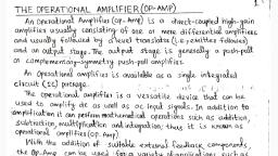
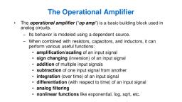
7 1,2,3 1,4, | 1.Op-amp: Block diagram, Symbol,, 6 | Basic differential amplifier- Working | Refer Table 1 | 1. Identify Op-amp IC, its, principle. pins and Interpret its data, sheet., 2. Modes of operation-Single ended,, Common mode & Differential mode, 2. Conduct an experiment, Ideal and practical characteristics. to find the practical, characteristics of Op-amp, 3.O0p-amp parameters: Input offset and compare them with, voltage, input offset current, power ideal characteristics., supply rejection ratio, CMRR, Input, and output impedance, gain, gainbandwidth product, slew-rate, 8 3,4 1,4, | 1. Open-loop configuration: 1, Construct and test an, 6 Comparator-inverting, non-inverting, op-amp circuit to obtain, applications, disadvantages. Inverting & Non inverting, output., 2. Closed-loop configuration: virtual Refer Table 1, ground, applications - inverting, non- 2. Construct a circuit to, inverting amplifier. obtain the, Sum/ Difference of all, 3. Voltage follower, summing & input voltages., difference amplifiers., 9 3,4 1,3, | 1. Construct and verify Op-amp as 1. Construct a circuit to, 4,6 | Differentiator, Integrator. obtain triangular wave, and spike from square, 2. Op-amp as Schmitt trigger and wave,, precision rectifier, Gain of Multistage, Op-Amp Circuits. Refer Table 1 | 2. Build an op-amp circuit, to generate clock pulses, 3. Sinusoidal Oscillators, Types of and verify its working., Oscillations, LC Tank circuit and, stability., 10 3,4 1,3, | 1. Concept of feedback and types, 1. Construct/Simulate, 4,6 | Barkhausen criteria. Hartley oscillator using, BJT. Verify the same using, 2. Types of Oscillators, Working of op-amp., Hartley oscillator using BJT/Op-amp Refer Table 1, and its applications. 2. Construct, test and, Troubleshoot Colpitts, 3. Working of Colpitts and crystal oscillator using BJT/oposcillator using BJT/Op-amp and their amp., applications, 11 3,4 1,3, | 1. Working of RC phase-shift and 1. Design and implement, 4,6 | Wein-bridge oscillators using Op-amp /Simulate RC phase shift, and their applications. oscillator for generating a, frequency of 1khz using, 2. Filters: Classification, Applications & BJT. Verify the same using, Advantages of Active over Passive Refer Table 1 | op-amp., Filters,, 2. Conduct an experiment, 3. Filter Terminology, frequency to plot the frequency, response of 1st order Butterworth response of LPF & HPF., LPF, HPF (No Derivation)., Department of Collegiate and Technical Education, Government of Karnataka 7
Page 4 :
12 3,4 1,3, | 1. Frequency response of 1st order 1. Build an, 4,7 | Butterworth BPF and Band . : os, ee 7 Instrumentation Amplifier, Elimination Filter, BEF a, (No Derivation) Circuit to detect and, Refer Table 1 | A™Plify Analog/Bio5 Kes Potential Signals (using, 2. Instrumentation amplifier-Need for . ., + : i . simulator or video to be, instrumentation amplifier, Working of, ; ‘ ffics. deacorh displayed), instrumentation amplifier circuit., 3. Phase Locked Loop (PLL): voltage to, frequency converter, PLL operation 2. Verify the working of, with mention of its applications PLL using a simulator., 13 1,3,4 1,3, | 1.1C 555 Timer: Internal diagram, Pin 1. Verify the working of IC, 4 Configuration. Interpret Datasheets. 555 timer as astable, multivibrator., 2.1C 555 timer as Astable Refer Table 1, multivibrator. 2. Verify the working of IC, 555 timer as monostable, 3.1C 555 timer as monostable multivibrator., multivibrator,, Total in hours 39 13 52, , , , , , , , , , , , , , Note: 1) In Practice sessions Video demonstration should be followed by MCQs/Quiz/Subjective, questions and the evaluation has to be documented., , 2) In Practice sessions, all discrete circuits should be simulated using suitable software before its, construction and verification., , TABLE 1: Suggested activities for tutorials, The list is shared as an example and not inclusive of all possible activities of the course., , The list of activities for one week can be shared among teams in a batch of students., , , , , , Week. Suggested activities for tutorials, No., , 1. Gather knowledge and give a presentation on the type of power supply used in mobile, 01 charger, desktop computer and laptop with its specifications and Justify., , 2. Build a Notch Filter to reject 50 Hz noise in power supplies and demonstrate it in the class., , 3. Identify the type of UPS used in the lab, its specifications, analyze its load carrying capacity, related to its power factor and prepare a report on it., , , , , , 1. Design and build a circuit that can store maximum voltage of the input signal (Peak Detector), 02 and demonstrate it in the class., , 2. Prepare a report on any one application of peak detector in daily life, also compare the nature, of output ofa rectifier and a peak detector., , 3. Prepare a video of a circuit which increases the input voltage 4 times. (Quadrupler)., , , , , , , , Department of Collegiate and Technical Education, Government of Karnataka 8
Page 5 :
03, , 1. Give a presentation on the use of opto isolator to detect DC or control AC signals and data., 2. Demonstrate the use of PIN diode as a switch in domestic applications,, , 3. Build a power supply switching circuit using optocouplers., , , , 04, , 1, Prepare a report on applications of each type of amplifier and present it., , 2, Demonstrate any one real life application of an amplifier., , , , 05, , 1, Prepare a report and explain a specific application of emitter follower in daily life. (Ex: as, switching circuit, isolator circuit, voltage buffer, impedance matching circuit)., , 2. Prepare a presentation on comparison of power amplifiers., , , , 06, , 1, Prepare a video/report on any one real life application of a power amplifier., 2. Build and demonstrate radio player amplifier circuit., , 3. Give a presentation on low noise amplifiers., , , , 07, , 1. Explain the criteria for selecting an op-amp for a given application., , 2. Identify at least 5 electronic circuits using op-amp and present the details of its working., , , , 08, , 1, Prepare a report on comparison of transistor amplifier and op-amp., , 2. Demonstrate the operation of auto cut for manual stabilisers using 741 IC., , , , 09, , 1, Explain how an op-amp can be used in applications such as A/D converters, wave shaping, drcuits etc., , 2. Prepare a report on Schmitt trigger applications such as switch debouncing, noise removal, etc., , , , 10, , 1, Demonstrate the operation of a variable audio frequency oscillator using op-amp 741., , 2. Explain the working of FM radio jammer., , , , 11, , 1. Discuss the problems to design and analyse 1st order butterworth filters., , 2, Demonstrate how LEDs can be made to blink on the beats of music., , , , , , 12, , , , 1. Prepare a report on different applications of instrumentation amplifier, , 2. Explain the operation of Frequency Shift Keying (FSK) generator using PLL 565., , , , Department of Collegiate and Technical Education, Government of Karnataka