Page 1 :
MAHARASHTRA STATE BOARD OF TECHNICAL EDUCATION, (Autonomous), (ISO/IEC -270001 – 2005 Certified), , Subject code: 17419, 22301, , WINTER -2019 EXAMINATION, , Model Answer, Important Instructions to the Examiners:, 1) The answer should be examined by keywords and not as word-to-word as given in the model answer, scheme., 2) The model answer and the answer written by candidate may vary but the examiner may try to assess, the understanding level of the candidate., 3) The language error such as grammatical, spelling errors should not be given more importance. (Not, applicable for subject English and communication skill)., 4) While assessing figures, examiner may give credit for principal components indicated in the figure., The figure drawn by candidate and model answer may vary. The examiner may give credit for any, equivalent figure drawn., 5) Credits may be given step wise for numerical problems. In the some cases, the assumed constants, values may vary and there may be some difference in the candidates answer and model answer., 6) In case of some questions credit may be given by judgment on part of examiner of relevant answer, based on candidates understanding, 7) For programming language papers, credit may be given to any other program based on equivalent, concept., , Que, No, 1., a), Ans:, , b), Ans:, , Question and Model Answers, Attempt any FIVE of the following:, State two advantages of plane table surveying, 1.it is most rapid method of surveying., 2. it is suitable for magnetic areas., 3.The map can be prepared easily ,and does not require greater skill., 4.Irregular objects can be represented accurately., 5.There is no possibility of overlooking any important object., 6. It is less costly., 7 The check lines detects the errors of measurement and plotting on field itself., Define Swinging & Transiting, Swinging: It is the process of turning the telescope in horizontal plane about its vertical axis., Transiting;It is the process of turning the telescope through 180° in a vertical plane about its, , Marks, 10, , 1M, each, (any, two), , 1M, each, , horizontal axis, , c), Ans:, , Define Latitude and Departure., Latitude : The projection of survey line parallel to meridian is called latitude., , OR Projection of survey line parallel to N-S direction is called latitude., 1M, each, Departure: The projection of survey line perpendicular to meridian is called departure., OR Projection of survey line parallel to E-W direction is called departure., winter-2019, 22301ASU, 1|17
Page 2 :
d), Ans:, , e), Ans:, f), Ans:, , g), Ans:, , State the function of Anallatic lens.., The function of anallatic lens is to make additive constant zero i.e.(f+d)=0, It simplifies the calculation., Define degree of curve., The angle subtended at the centre of the circle by a chord of standard length of 30m is, known as degree of curve., List two uses of EDM., 1.It is useful for measuring the distances that are difficult to access., 2. It is useful in topographical survey., 3.Measurement of base line in triangulation survey can be carried out speedily and, accurately., 4.Measuremnt of distances in difficult work sites such as construction of gravity dams., 5.It is useful in fixing alignment of road, railways, canals etc., Name two software for GPS., Softwares for GPS, 1).GPSWOX 2) iGO, , 3) HERE, , 4)Navigon, , 5)Navman, , 6)EasyGPS 7) Caliper, , 2., , Attempt any THREE of the following, , a), , Describe any one method of orientation of plane table surveying, , Ans:, , 2M, , Orientation by back sighting method:, This method is accurate and is always preferred., Procedure:, 1.Suppose A and B are two stations.The plane table is set up over A. The table is, leveled by spirit level and centerd over station A so that point ‘a’ is just over station, A. The north line is marked on the right hand top corner of the sheet by trough, compass., 2. With alidade touching a, the ranging rod at B is bisected and a ray is drawn. The, distance AB is measured and plotted to any suitable scale .so, the point b represents, Station B., 3.The table is shifted and set up over B. It is leveled and centered so that ‘b’ is just, over B. Now the alidade is placed along the line ba, and the ranging rod at A is, bisected by turning the table clockwise or anticlockwise . At this time the centering, may be disturbed, and should be adjusted immediately if required. When the, centering ,leveling and bisection of ranging rod at A are perfect ,then the orientation, is said to be perfect., , 2M, 1M, each, (any, two), , 2M, for, any, two, 12, , 2M, exp, , 2M, fig., , 2|17, , winter-2019, , 22301ASU
Page 3 :
OR, 2.Orientation by magnetic needle:, Procedure:, This method is suitable when local attraction is not suspected in the area., 1. Suppose A and B are two stations. The plane table is set up at station A. The, centering is done by U-frame so that the point ‘a’ is just over A. Then the, trough compass is placed on right hand top corner of the sheet in a such way, that the needle coincides 0-0 mark. After this a line representing the north, line is drawn through edge of the compass box., 2. With the alidade touching the point ‘a’ ,the ranging rod at B is bisected and a, ray is drawn. The distance AB is measured and plotted to any suitable scale., 3. The table is shifted and centered over B, so that the point b is just over B., The table is leveled .Now the trough compass is placed exactly along the, north line drawn previously. The table is turned clockwise or anticlockwise, until the needle coincides exactly with the 0-0 mark of the compass., 4. While turning the table ,care should be taken not to disturb centering. In, case it is ,it should be adjusted immediately., 5. While the centering and leveling are perfect and needle is exactly at 0-0 ,, the orientation is said to be perfect., , 2M, exp, , 2M, fig., , b), Ans:, , 3|17, , Explain the temporary adjustment of theodolite., Temporary Adjustments:, The temporary adjustments have to be carried out at every setup of the instrument before, taking observations with the theodolite, A)Setting up:, 1) Place the instrument over the station by spreading the tripod legs well apart at a, convenient height., 2) Suspend a plumb bob from the hook approximately over the station point so that the, plumb bob hangs about 2 cm above station point., 3) Bring the plumb bob exactly over the station point by moving each leg radially as well, as circumferentially, and then press the legs firmly into the ground. By doing this the, instrument is approximately leveled also., 4) If shifting head is provided the instrument, centering can be done rapidly. On hill side, to ensure greater stability, place two legs of tripod down hill and the third leg uphill., winter-2019, , 22301ASU, , ., , 1M
Page 4 :
B)Leveling up of theodolite:, , 1) Turn the theodolite about its vertical axis until the plate level is parallel to any pair of, leveling screws., 2) Bring the bubble to the centre of its run by turning both foot screws uniformly. By, using thumb and forefingers, move the foot screws either towards each other or away, from other., 3) Turn the instrument through 900 so that the bubble line will be at right angle to its, previous position. Now, move only the third foot screw either in or out till the bubble is, brought to the centre of its run., 4) Repeat the process until finally the plate bubble is exactly centered in both the, positions., 5) Now rotate the theodolite about the vertical axis through 3600. The bubble will remain, central provided it is in correct adjustment. The vertical axis is thus made truly vertical ., C) Focusing the eye piece :, The object of focusing the eye piece is to make the cross hairs on diaphragm distinct and, clear. To do this, direct the telescope towards the sky or hold a sheet of white paper in, front of the object glass, and move the eye piece circumferentially or in or out until the, cross hairs are seen sharp and black., D) Focusing of object glass :, The object of focusing the glass is to bring the image of the object formed by the object, glass exactly in the plane of cross hairs. If not done accurately, there will be an apparent, movement of the image relatively to the cross hairs when the observer moves eye up and, down. This effect is known as parallax. The parallax can be removed by the sharp, focusing until the image appears sharp and clear., c), Ans:, , 1M, , 1M, , 1M, , Explain the principle of techeometry with the help of a neat sketch., Principle of tacheometry is based on principle of similar triangle in which, corresponding sides & altitudes are proportional The ratio of distance of base from apex, and length of base is always constant., In fig. Oa1a2, Ob1b2, Oc1c2 are all isosceles triangles where D1, D2, D3 are the distances of, bases from the apices (distances of staff stations from instrumnt stations) and S1, S2, S3 are, the lengths of the bases also called staff intercepts., According to stated principle., D1/S1 = D2/S2=D3/ S3=f/i=Constant, Where f=focal length of objective and i =stadia intercept, , Expla, nation, 3M, , 1M, sketch, , d), , Draw a simple circular curve and show the following on it, (i) Forward Tangent ( ii) Long Chord (iii) Deflection angle (iv) Apex distance, 2M, , a), 4|17, , winter-2019, , 22301ASU
Page 5 :
sketch, , 2M for, notati, on), , ., BC is Known as forward tangents., T1 DT2 is known as long chord., The angle Ø is known as deflection angle., BE is known as Apex distance., Q.3, a), Ans:, , Attempt any THREE of the following:, , 12M, , Describe the procedure of measurement of horizontal angle by repetition method., Procedure:, 1 Suppose the angle AOB is to be measured by the repetition process. The theodolite is set, 0, over O. The instrument is centered and levelled properly.Vernier A is set at 0 and vernier, 0, is at 180, 2.The lower plate is loosened.By turning the telescope the ranging rod at A is perfectly, bisected with the help of lower clamp and tangent screw. Here the initial reading of vernier, A is 00, 3.The upper clamp is loosened and telescope is turned clockwise to perfectly bisect, ranging rod at B by using upper clamp and tangent screw.Suppose the reading on vernier, A is 300, 4.The lower clamp is loosened and telescope turned to exactly bisect the ranging rod at A, 0, by lower plate clamp and tangent screw.Here the initial reading is 30 for second, observation., 5. The upper plate is loosened and the telescope is turned to exactly bisect the ranging rod, at B by using upper clamp and tangent screw..Let the reading on vernier A is 600, 6 The procedure is repeated for one more time., 7.The face of the instrument is changed and the previous procedure is followed., 8 The mean of the two angles obtained from two faces gives the actual angle AOB., , 3M, Pro., , 1M, Fig., 5|17, , winter-2019, , 22301ASU
Page 6 :
b), , Explain the working principal of EDM with a neat sketch., , Ans:, , 2M, Fig., , ., , , , Let the distance between P and Q be ‘D’ which is to be measured., , , , A wave transmitted from the transmitter at station ‘P’ with certain phase angle., There is a reflector at the other end ‘Q’ Reflector consist of prism. The wave strikes, on reflector at Q and then gets reflected from Q., , 2M, Pro., , It is received back at the transmitter end at ‘P’ with different phase angle. For, ., , finding the distance, the phase difference between transmitted and reflected waves is, measured and converted into distance., , c), Ans:, , Describe the procedure to measure vertical angle by using electronic theodolite., Digital Theodolite for measurement of vertical angle., 1)Taking out digital theodolite for box and fix it on tripod over required station., 2) Accurate centering and aapproximate leveling by leg adjustment is done.., 3) Levelling the digital theodolite using foot screws by usual method i.e. plate level, parallel to pair of foot screw and perpendicular position, 4) Focusing of eyepiece and object glass is done using eyepiece and focusing screws., 5) Switch on the digital theodolite., 6) Direct the telescope toward the object of which angle is to be measured say A, bisect it., Clamp the instrument, accurate bisection is done by slow motion screw.one., 7) Press hold button, LCD gives required vertical angle from zenith point or horizantal, plane as per setting of the instrument., , Note: Procedure may vary slightly as per make and model of instrument., , d), Ans:, , Describe the procedure to determine co-ordinates of a station using GPS., The following are some general GPS field survey procedures that should be performed at, each station, observation, and/or session on a GPS survey., A. Receiver setup, GPS receiver shall be set up in accordance with manufacturer’s specification prior to, beginning any observation. To eliminate any possibility of missing the beginning of the, observation session, all equipment should be set up with power supplied to the receivers at, least 10 minutes prior to the beginning of the observation session. Most receivers will, , 6|17, , winter-2019, , 22301ASU, , 4M
Page 7 :
lock-on to satellites within 1-2 min of powering up., B. Antenna setup., All tribrachs used on a project should be calibrated and adjusted prior to beginning each, project. Dual use of both optical plummets and standard plumb bobs is strongly, recommended since centering errors represent a major error source in all survey work, not, just GPS surveying., C. Height of instrument measurements., Height of instrument (HI) refers to the correct measurement of the distance of the GPS, antenna above the reference monument over which it has been placed. HI measurements, will be made both before and after each observation session. The HI will be made from the, monument to a standard reference point on the antenna .These standard reference point for, each antenna will be established prior to the beginning of the observation so all observers, will be measuring to the same point. All HI measurements will be made in meters. HI, measurements shall be determined to the nearest millimeter in metric units. It should be, noted whether the HI is vertical or diagonal., D. Field GPS observation recording procedures., Field recording books, log sheet, or log forms will be completed for each station and/or, session. Any acceptable recording media may be used. For archiving purpose, standard, bound field survey books are preferred. However, USACE Commands may require, specific recording sheet/forms to be used in lieu of a survey book. The amount of record, keeping detail will be project-dependent. Low-order topographic mapping points need not, have as much descriptive information as would have for permanently marked primary, control points . The following typical data may be included on these field log records:, 1) Project, construction contract, observer(s) name(s), and/or contractor firm and contract, number., 2) Station designation., 3) Station file number., 4) Date, weather conditions, etc., 5) Time, start/stop session (local and UTC)., 6) Receiver, antenna, data recording unit, and tribrach make, model, and serial numbers., 7) Antenna height: vertical or diagonal measure in inches (or feet) and meters., 8) Space vehicle designations (satellite number)., 9) Sketch of station location., 10) Approximate geodetic location and elevation., 7|17, , winter-2019, , 22301ASU, , 4M
Page 8 :
11) Problems encountered., E. Field processing and verification., It is strongly recommended that GPS data processing and verification be performed in the, field where applicable. This is to identify any problem that may exist which can be, corrected before returning from the field., Note: Above procedure is general procedure. Actual co-ordinate measurement procedure will, be as per make and model of GPS. Give credit accordingly., , Q.4, a), , 12M, , Attempt any THREE of the following:, Compare radiation and intersection methods of plane table surveying on any two, parameters., , Ans:, , Radiation method, , Intersection method, , 1. It requires the plane table to occupy a 1. This method requires setting the table, single station., up at minimum of two stations., 2. Orientation table is not required., 2. Orientation is essential and can be done, by back sighting., 3. To conduct the survey of an area, the 3. Two station A and B are selected so that, table is kept at a convenient station A, they command a full view of the area, commanding a full view of the area to, to be surveyed., be surveyed., 4. In this method, rays are drawn from the 4. In this method distance of base lene only, station to the objects, and the distance, is measured. Distance of object from, from the station to the object are, station is not measured, measured and plotted to any suitable, scale along respective rays., 5 This method is suitable when points to be 5 This method is suitable for locating, inaccessible points by the intersection, plotted are within accessible from single, of the rays drawn from two instruments, station., stations., , b), , Ans:, , Following are the lengths and bearings of a closed traverse ABCDA., Line, , Length(m), , Bearing, , AB, , 258.0, , 300, , BC, , 321.0, , 1400, , CD, , 180.0, , 2100, , DA, , ?, , ?, , Calculate the length and bearing of the Line DA., For closed traverse ∑L = 0, ∑D=0, Line, , Length(m) Bearing, , Reduced, Bearing (θ), , 8|17, , Latitude, = l*cos θ, , winter-2019, , Departure, = l*sin θ, 22301ASU, , 2M, , each, (any, two)
Page 9 :
AB, , 258.0, , 300, , N 300 E, , +223.43, , +129.00, , BC, , 321.0, , 1400, , S 400 E, , -245.90, , +206.33, , CD, , 180.0, , 2100, , S 300 W, , -155.88, , -90.00, , DA, , ?, , ?, , L, , D, , θ, , 1M, , ∑L = 0, Therefore, +223.43-245.90-155.88+L = 0, L = 178.35, , ½M, , ∑D = 0, Therefore, +129+206.33-90+D = 0, D = -245.33, tanθ = D/L= 245.33/178.35, , ½M, , θ = 53 59’0.95”, 0, , Since latitude is +ve and Departure is –ve ,hence line DA lies in NW Quadrant, Bearing of line DA= N 530 59’0.95”W, Length of line DA = √((L)2+(D)2), , 1M, , 2, , 2, , = √ ((178.35) +(245.33) ), Length of line DA = 303.30 m., 1M, , c), , Ans:, , 9|17, , Following are the corrected latitudes and departures of a closed traverse. Find the, independent co-ordinates of the points of traverse., Side, , Latitude, , Departure, , AB, , +225.5, , +120.5, , BC, , -245.0, , +210.0, , CD, , -150.5, , -110.5, , DA, , +170.0, , -220.0, , For independent coordinates:, Line, , Station, , Latitude, , Departure, , AB, , A, , +225.5, , +120.5, , BC, , B, , -245.0, , +210.0, , winter-2019, , Indepandent co-ordinates, , Northing, 1000, assumed, 1225.5, , Easting, 1000, assumed, 1120.5, 22301ASU, , ½M, each, cal., for
Page 10 :
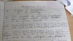
CD, , C, , -150.5, , -110.5, , 980.5, , 1330.5, , DA, , D, , +170.0, , -220.0, , 830, , 1220.0, , Check, AB, , A, , 1000, , 1000.0, , Assume north co-ordinate of A=1000, Add northing of B =225.5, North co-ordinate of B =1225.5, Deduct southing of C =245.0, North co-ordinate of C =980.5, Deduct southing of D =150.5, North co-ordinate of D = 830, Add northing of A, =170, North co-ordinate of A =1000 (check ok), Assume East Co-ordinate of A=1000, Add easting of B=120.5, East Co-ordinate of B=1120.5, Add easting of C=210.0, East Co-ordinate of C=1330.5, deduct westing of D=110.5, East Co-ordinate of D=1220, Deduct westing of A=220, East Co-ordinate of A=1000 (check ok), , Note: Students may assume different N and E co-ordinates of A.Final check sould tally with, assumed co-ordinates., , d), , Following observation were taken to determine the constants of tachometer., Station, , Staff, Station, , Horizantal, distance, (m), , vertical angle, , Hair Readings, Lower, , Upper, , A, , B, , 51.430, , 6030', , 0.900, , 1.420, , A, , C, , 18.065, , 2020', , 1.140, , 1.320, , Determine the constants., Ans:, Horizontal Distance, X= f/i S cos2 θ + (f+c) cos θ, 51.430 = f/i (1.420-0.900) cos2 6030' + (f+c) cos 6030', 51.430 = 0.520 f/i + 0.994(f+c) ……………………… Equation (I), X= f/i S cos2 θ + (f+c) cos θ, 18.065= f/i (1.320-1.140) cos2 2020' + (f+c) cos 2020', 18.065 = 0.180 f/i + 0.999(f+c) ……………………… Equation (II), Divide Equation (I) by 0.520 and Equation (II) by 0.180, 98.904= f/i + 1.911(f+c) …………………… Equation (III), 100.360= f/i + (f+c) 5.550…………………….Equation (IV), Subtract Equation (III) from Equation(IV), 10 | 1 7, 22301ASU, , winter-2019, , N, &, E
Page 11 :
e), Ans:, , 100.360= f/i + 5.550(f+c), -98.904= -f/i - 1.911(f+c), 1.456 = 3.639(f+c), (f+c) = 0.400, Put this value in Equation (III), 98.904= f/i + (0.400) x (1.911), 98.904= f/i + (0.764), f/i= 98.140, Constants of tacheometrer are:, 1) Additive constants (f+c) = 0.400, 2) Multiplying constants f/i = 98.140, Note1: Marking scheme, Eq1=1M, Eq2=1M, Solving equtions to correct answers =2M, Note2: Students may follow different procedure to solve equations., Calculate the ordinates from long chord to set a circular curve at 10 m interval given, that the length of long chord is 60 m and radius of the curve is 180 m., , A versed sine or ordinate at center of long chord, O0 = R- √(R2-(L/2)2), , 1M, , O0 = 180 -√(180)2-(60/2)2, O0 = 180-177.48, O0 = 2.517 m, , 1M, , The ordinates at various distances 10, 20,30 etc are worked out by the formula., Ox = √(R2-X2) - (R- O0), O10 = √(180 -10 ) - (180 – 2.517), 2, , 2, , ½M, , O10 = 179.72 – 177.483, O10 = 2.239 m, O20 = √180 2-20 2 - (180 – 2.517), , ½M, , O20 = 178.88 – 177.483, O20 = 1.402 m, O30 = √180 2-30 2 - (180 – 2.517), , ½M, , O30 = 177.483– 177.483, , 5., a), , O30 = 0.0 m, Attempt any TWO of the following:, , The following angles were measured in running a closed traverse ABCDEA., ∠𝑨 = 𝟖𝟕°𝟓𝟎′𝟐𝟎′′, ∠𝑩 = 𝟏𝟏𝟒°𝟓𝟓′𝟒𝟎′′, ∠𝑪 = 𝟗𝟒°𝟑𝟖′𝟓𝟎′′, ∠𝑫 = 𝟏𝟐𝟗°𝟒𝟎′𝟒𝟎′′, ∠𝑬 =, 𝟏𝟏𝟐°𝟓𝟒′𝟑𝟎′′. If the bearing of line AB is 𝟐𝟐𝟏°𝟏𝟖′ 𝟒𝟎′′ , calculate bearing of the remaining, lines., winter-2019, 11 | 1 7, 22301ASU, , ½M, 12M
Page 12 :
b), , Ans:, Bearing of line AB = 𝟐𝟐𝟏°𝟏𝟖′ 𝟒𝟎′′, + ∠𝐵 = 114°55′40′′, 336°14′ 20′′, – 180° 0′ 0′′, Bearing of line BC = 𝟏𝟓𝟔°𝟏𝟒′𝟐𝟎′′, + ∠𝐶 = 94°38′50′′, 250°53′ 10′′, – 180° 0′ 0′′, Bearing of line CD = 𝟕𝟎°𝟓𝟑′𝟏𝟎′′, + ∠𝐷 = 129°40′40′′, 200°33′50′′, – 180° 0′ 0′′, Bearing of line DE = 𝟐𝟎°𝟑𝟑′𝟓𝟎′′, + ∠𝐸 = 112°54′30′′, 133°28′ 20′′, + 180° 0′ 0′′, Bearing of line EA = 𝟑𝟏𝟑°𝟐𝟖′𝟐𝟎′′, + ∠𝐴 = 87°50′20′′, 401°18′ 40′′, – 180° 0′ 0′′, = 221°18′40′′ = Bearing of line AB, , 1M, , 1M, , 1M, , 1M, , 1M, , 1M, , Hence O.K., Calculate the corrected consecutive co-ordinates for the following traverse. Apply, Bowditch Rule., Line, Length in ‘m’, Latitude, Departure, AB, 335, – 334.91, – 7.80, BC, 850, + 849.99, – 4.95, CD, 408, + 407.44, – 21.35, DA, 828, – 72.17, – 824.85, Ans:, Line, Length in ‘m’, Latitude, Departure, AB, 335, – 334.91, – 7.80, BC, 850, + 849.99, – 4.95, CD, 408, + 407.44, – 21.35, DA, 828, – 72.17, – 824.85, Total, 2421, – 4.59, – 4.01, Total error in Latitude = – 4.59 (Correction will be +ve), Total error in departure = – 4.01 (Correction will be +ve), Perimeter of traverse = 2421 m., By Bowditch’s rule,, Correction in latitude or departure =, 𝐿𝑒𝑛𝑔ℎ𝑡 𝑜𝑓 𝑡ℎ𝑒 𝑠𝑖𝑑𝑒, Total error in latitude or departure x { 𝑃𝑒𝑟𝑖𝑚𝑒𝑡𝑒𝑟 𝑜𝑓 𝑡ℎ𝑒 𝑡𝑟𝑎𝑣𝑒𝑟𝑠𝑒 }, Correction in latitude, 335, , Line AB = +4.59 x 2421 = + 0.64, 850, , Line BC = +4.59 x 2421 = + 1.61, , 12 | 1 7, 22301ASU, , 1M, , 1M, , Correction in departure, 335, , Line AB = +4.01 x 2421 = + 0.55, 850, , Line BC = +4.01 x 2421 = + 1.41, winter-2019, , 2M
Page 13 :
Line CD = +4.59 x, , 408, , 2421, , = + 0.77, , Line CD = +4.01 x, , 828, , 408, , 2421, , = + 0.68, , 828, , Line DA = +4.59 x 2421 = + 1.57, , Line DA = +4.01 x 2421 = + 1.37, , Corrected consecutive coordinates, , c), , Line, , Length, (m), , AB, BC, CD, DA, , 335, 850, 408, 828, , Consecutive, Latitude Departure, , – 334.91, – 4.95, + 407.44, – 72.17, – 4.59, , – 7.80, + 849.99, – 21.35, – 824.85, – 4.01, , Correction in, Latitude Departur, e, + 0.64, + 0.55, + 1.61, + 1.41, + 0.77, + 0.68, + 1.57, + 1.37, + 4.59, + 4.01, , Corrected Consec., Latitude Departure, , – 334.27, – 3.34, + 408.21, – 70.60, 0.00, , – 7.25, + 851.40, – 20.67, – 823.48, 0.00, , 2M, , A tacheometer was set up at a station P and following readings were taken on a vertically, held staff. The constant of the instrument was 100., Station, Staff, Vertical, Hair Reading, Remarks, Station, angle, P, BM, 1.050, 1.105, 1.160, RL of BM, – 4°𝟎′, = 200 m, P, Q, 0.950, 1.055, 1.160, + 10°𝟎′, The instrument was fitted with anallatic lens. Determine distance PQ and RL of Q., Ans:, GivenGiven- (f/i) = 100,, (f+d) = 0 (for anallatic lens), 𝜃1 = 4°0’, 𝜃2 = 10°0’, h1 = 1.105 m, h2 = 1.055 m, B.M. RL = 200.00 m, , Staff intercept at BM = S1 = 1.160 – 1.050 = 0.11 m, Staff intercept at B = S2 = 1.160 – 0.950 = 0.21 m, , 1M, , V1 at BM = (f/i)S1 x (sin2𝜃1)/2 + (f+d)sin 𝜃1, = 100 x 0.11 x sin(2x4°0’)/2 + 0, = 0.765 m, , 1M, , V2 at B = (f/i)S2 x (sin2𝜃2)/2 + (f+d)sin 𝜃2, = 100 x 0.21 x sin(2x10°0’)/2 + 0, = 3.591 m, Horizontal Distance PQ = (f/i)S2 x cos2 𝜃2 + (f+d) cos 𝜃2, , 13 | 1 7, 22301ASU, , winter-2019, , 1M, , 1M
Page 14 :
= 100 x 0.21 x cos2 10°0’ + 0, PQ = 20.37 m, RL of instrumental axis = RL of BM + h1 + V1, = 200.00 + 1.105 + 0.765, = 201.87 m, RL of station Q = RL of instrumental axis + V2 - h2, = 201.87 + 3.591 – 1.055, RL of station Q = 204.406 m, 6., , Attempt any TWO of the following:, , a), , Describe stepwise procedure to prepare the layout of a small building using total station., , 1M, , 1M, , Ans:, Layout of small building by using total station:, 1. On the plan supplied by an architect, number the column serially from left to right, 6M, and top to bottom starting from top left corner., (for, 2. Work out coordinates of column centre with respect to one plot corner or well, compl, defined point, assuming line parallel to any one face of building as meridian., ete, 3. Create an excel document with 4 independent columns one for column number and, rest three for N, E & H coordinates. Upload this file to total station by using proced, ure), transfer software provided with instrument., 4. Set the total station at site at a point with respect which the coordinates of column, centre are work out. Initiate the total station by proving with the coordinates of, station and by orienting the telescope along the reference meridian., 5. Now, activate the setting out programme of the total station. Open the uploaded file, & bring in the coordinates of any column to be set out., 6. Hold prism pole at tentative position of that column on ground, bisect it & get, measured its coordinates., 7. In next reading machine will display the discrepancies in the coordinates of the, point & point to be set out., 8. Direct the reflector man accordingly to occupy the new position, bisect him again, & get measured its coordinates to know the discrepancy., 9. Repeat the process till you get no discrepancy in the coordinates of point occupied, & point to be set out. In this way get marked centres of rest of the columns., 10. Check the accuracy of the process of setting out by comparing the diagonal, distance between the extreme column centres to their calculated values., b), , Apply knowledge of total station to prepare a contour map by describing its procedure., Ans:, Procedure of preparing contour map using total station1) Preliminary set up –, Fix the total station over a station and level it., Press the power button to switch on the instrument. level instrument using, electronic vial. Set bisection target as prism., Select MODE B -------> S function------->file management------>create (enter a, name)------->accept., Then press ESC to go to the starting page., , 14 | 1 7, 22301ASU, , winter-2019, , 6M*
Page 15 :
2) Then go to S function ------> measure-----> rectangular co-ordinate---->station -->press enter. Here enter the point number or name, X,Y,Z co-ordnates, instrument, height and prism code. Then press accept (Fs), 3) Adopt Cross section method for establishing the major grid around the study area., Project suitably spaced cross sections on either side of the centre line of the area., Choose several points at reasonable distances on either side., 4) Orient the instrument to the magnetic north, or any other referance direction. Then set, zero by double clicking on 0 set (F3)., 5) Keep the reflecting prism on the first point and turn the total station to the prism, focus, it and bisect it exactly using horizontal and vertical clamps. Then select MEAS and the, display panel will show the point specification. Now select edit and re-enter the point, number or name point code and enter the prism height that we have set., 6) Then press MEAS/SAVE (F3) so that the measurement to the first point will, automatically be saved and the display panel will show the second point. Then turn the, total station to second point and do the same procedure. Repeat the steps to the rest of, the stations and get all point details., 7) Transfer the data stored in file to computer in the appropriate format., 8) Using appropriate application software, contour map will be prepared., , *(Note- Student may write procedure, depending upon the make and, model of total station used for practical and software used., Give credits accordingly.), c), , Demonstrate the utility of Remote Sensing and GIS applications in Civil Engineering, with appropriate examples., AnsApplications of Remote Sensing in Civil Engineering1) Silting of storage reservoirs harbors etc. – Remote sensing technique that makes, use of satellite imagery gives idea about the silting of reservoir qualitatively and to, some extent quantitatively., 2) Location of Percolation Tanks – The exact location of percolation tanks can be, carried out with the help of remote sensing technique, keeping in view that the site, required for location of percolation tanks should be on permeable foundations., 3) Revision of existing topo sheets - The rapid revision and updating of existing topo, (graphical) sheets can be carried out speedily with the help of aerial photography, and satellite imagery., 4) Alignment of new highways and rail routes – The location of most economical, alternative sites for such works can very well be carried out speedily by making use, of aerial photographs and satellite imagery., 5) Location of Bridge site: The existing foundation condition along the proposed, bridge construction site can be ascertained with the help of aerial photographs and, or satellite imagery., 6) Location of Dam sites: For gravity, geological investigations of the existing rock in, and around the proposed dam site can be carried out by aerial photographs and or, satellite imagery. Geological features such folds, faults, dykes, fractures etc. can be, determined by the remote sensing technique., 7) Tunneling: Remote sensing i.e. aerial photography and or satellite imagery of the, area helps in furnishing all such information and thus ensures the safety of tunnel, during its construction stages., 8) Seepage losses in canals: Monitoring of soil moisture in and around the canal, system can be possible by remote sensing technique i.e. by careful study of aerial, photographs and satellite imagery of such areas., , 15 | 1 7, 22301ASU, , winter-2019, , 3M, (for, any, three)
Page 16 :
Applications of GIS in Civil Engineering1) Map making, 2) Site selection, 3) Mineral Exploration, 4) Land use planning and management, 5) Environmental Impact studies, 6) Natural Hazard mapping or assessment, 7) Water Resources availability., , 16 | 1 7, 22301ASU, , winter-2019, , 3M, (for, any, three)