Page 1 :
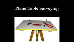
MAHARASHTRA STATE BOARD OF TECHNICAL EDUCATION, (Autonomous), , , , (ISO/IEC -270001 — 2005 certified), , , , SUMMER -2019 EXAMINATION, Subject code: 22301 Model Answer, Important Instructions to examiners:, , 1) The answer should be examined by keywords and not as word-to-word as given in the model, answer scheme., , 2) The model answer and the answer written by candidate may vary but the examiner may try to, assess the understanding level of the candidate., , 3) The language error such as grammatical, spelling errors should not be given more importance. (Not, applicable for subject English and communication skill)., , 4) While assessing figures, examiner may give credit for principal components indicated in the figure., The figure drawn by candidate and model answer may vary. The examiner may give credit for any, equivalent figure drawn., , 5) Credits may be given step wise for numerical problems. In the some cases, the assumed constants, values may vary and there may be some difference in the candidates answer and model answer., , 6) In case of some questions credit may be given by judgment on part of examiner of relevant answer, based on candidates understanding, , , , , , , , , , , , , , , , , , , , , , , , Q. Question and Model Answers Marks, No., 1. Attempt any FIVE of the following: 10M, a) State the purpose of alidade and ‘U’ fork in plane table surveying., Ans: In plane table surveying, purpose of—, 1) Alidade — 1) to sight the object and 2) to draw or plot sight rays., 1M, 2) ‘U? fork — for centering the plane table. (each), b) Define swinging and transiting in theodolite surveying., Ans: In theodolite surveying,, 1) Swinging —The turning of telescope about the vertical axis in horizontal plane, is termed as swinging. 1M, (each), 2) Transiting —-The method of turning the telescope about its horizontal axis in a, vertical plane through 180° is termed as transiting., c) What is face left and face right observations., Ans: Face left observations — The observations taken with the vertical circle of, instrument on the left side of the observer, are called face left observations., 1M, 1) Face right observation — The observations taken with the vertical circle of | (each), instrument on the right side of the observer, are called face right observations., , , , 1jJ11 Summer-2019 ASU-22301
Page 2 :
d), , State the principle of tacheometry., , , , Ans:, , Principle of Tacheometry —The principle of tacheometry is based on the property of, isosceles triangles, where the ratio of the distance from the apex and the length, of the base is always constant., , , , S1 S2 $3, Where f= focal length and i= stadia intercept, , (*Note- Student may draw figure to explain principle,, give credit as IM for figure and 1M for equation.), , 1M*, , 1M, , , , e), , Define horizontal curve and vertical curve., , , , Ans:, 1) Horizontal curve —When the curve is provided in horizontal plane, it is, called as horizontal curve., , 2) Vertical curve — When the curve is provided in vertical plane, it is called as, vertical curve., , 1M, (each), , , , State uses of Total station., , , , Ans:, Uses of Total Station —, 1) To measure horizontal, vertical and sloping distance., 2) To measure horizontal and vertical angles., 3) To measure the level difference between different points., 4) To carry out contouring., 5) To prepare the map and drawings using software., 6) To prepare layout of building, 7) To measure area and volume., , 2M, (for, any, four, uses), , , , 8), , State uses of GPS., , , , Ans:, Uses of GPS —, 1) To determine position or locations., 2) To navigate from one location to another., 3) To create digitized map., 4) To determine distance between two points., 5) Used in remote sensing., 6) Used in military and space., 7) To track or monitor object or personal movement., 8) To locate geographical features., , 2M, (for, any, four, uses), , , , Attempt any THREE of the following:, , 12M, , , , a), , Define orientation and explain back sight method of orientation with sketch., , , , , , , , Ans:, , Orientation, The process of keeping the table at each successive stations parallel to the position, which it occupied at the first station is known as orientation. OR, , The process by which the positions occupied by the board at various survey stations, are kept parallel is known as orientation., , Back sight method of Orientation1) The table is set up on first station A and next station B is bisected with the, , , , 1M, , , , 2411, , Summer-2019 ASU-22301
Page 3 :
help of alidade and lineab is drawn with appropriate scale., 2) On moving the table to the next station B, the table is oriented with the help | 2M, of alidade., 3) The alidade is kept parallel to line ab and the table is rotated until the line of, sight bisects the first station A., 4) The board is clamped properly without disturbing the centering., 1M, a b a b, Station A Station B, b) | State functions of optical plummet and shifting head in theodolite., Ans: Functions of1) Optical plummet, a) An optical plummet to be used in combination with a surveying, instrument or theodolite., b) Itis used for centering the theodolite over the station point. 2M*, c) The optical plummet replaces the conventional plumb bob, in which a, pointed weight is provided at the end of a string., d) It has the advantage thereover that it can be more precisely set than the, conventional plumb bob. It is unaffected by the wind., 2) Shifting head, a) Shifting head contains two parallel plates which are moved one over the, other within small area. Shifting head lies below the lower plate., b) Itis useful for exact centering of the whole instrument over the station. 2M*, c) Itis done after initial setting of instrument., d) It is done by unclamping the screw and the upper plate of the shifting, head is slid over the lower one until the plumb bob is exactly over the, station mark., (*Note-2M for any two points of each.), c) Explain method of repetition of horizontal angle measurement., Ans:, Method of repetition of horizontal angle measurement1) Set-up the theodolite over station O and level it properly., 2) Set the vernier A and vernier B at 0°0’0” and 180°0°0” respectively on the, horizontal graduated scale. This is done by loosening the upper clamp and moving, the upper plate until the zero of the vernier plate A coincides with the zero of the, main scale. Tighten both the clamps., 3) Loosen the lower clamp and bisect point A, the readings in vernier A and vernier | 3M, B should be 0°0°0” and 180°0’0” respectively. Minor adjustment in reading is done | (for, by lower tangent screw. method, 4) Loosen the upper clamp and bisect point B. Point B is accurately bisected using | ), upper tangent screw. Tighten both the clamps and note the readings in both verniers., 5) Tighten the upper clamp and rotate the telescope either in clockwise or, anticlockwise until it bisects point A. The readings in the vernier should remain the, same. Loosen the upper clamp and bisect point B. Point B is accurately bisected, using upper tangent screw. Tighten both the clamps and note the readings in both, verniers. This time vernier A will be twice of the earlier angle., 3]11 Summer-2019 ASU-22301
Page 4 :
6) In the same way take the angle for the third time., 7) Read the final angle. The average angle by face left will be the accumulated angle, divided by 3., 8) Change the face of the theodolite and repeat the same procedure., 9) The mean of both angles gives the horizontal angle AOB., 8 1M, (for, Fig.), o, d) | Explain with sketch notations of simple circular curve., Ans:, aN, | ay 2M, fe A . (for, » be sketch), Elements of simple curve, . 2M, Where: Notations are as follows - (for, 1) AB and BC are two tangents 5) T) ET? is length of curve. any, 2) BTiand BT2are lengths of tangents 6) R is Radius of curve. four, 3) BE are Apex distance. 7) TiDT2are length of long chord | notatio, 4) DE are Versed sine ns), 3. Attempt any THREE of the following: 12M, a) Explain measurement of bearing of line using theodolite., Ans:, Measurement of Bearing of line using theodolite:, Consider a Line AB _ whose bearing is to be measured by using theodolite., 1. Fix the instrument to the tripod stand and set the instrument exactly over, station A., 2. Centre the theodolite, level it by using three foot screws and make the bubble | 4M for, exactly centre of tube with face left condition. proper, 3. Unclamp the both plate clamping screw and set vernier A to 0° and vernier B | sequen, to 180° and clamp the both the plate screw. ce, 4. Unclamp lower plate screw and swing the telescope in horizontal plane, keeping face left condition., 5. Place the trough compass exactly at the attachment provided to fix trough, compass at the top of the standards., 6. Swinging the telescope fix the lower plate clamp when trough compass shows, exactly north., 4jii Summer-2019 ASU-22301
Page 5 :
7. Unclamp the upper plate screw and bisect the ranging rod at B exactly and, clamp the upper plate screw and take the readings on vernier A and Vernier B, and note in the field book., , 8. Repeat the same procedure with face right condition and mean of the both the, readings give the correct bearing of the line AB., , , , b), , State any four essential characteristics of tacheometer., , , , Ans:, , 1. The value of constant fe 100, where f is focal length and i= length of image., , 2. The telescope when fitted with anallatic less, the value of (f+c) should be zero., , 3. One should get clear and bright image even of long distance object., , 4. The telescope should be powerful, the magnification should be 20 to 30 times, Diameter., The aperture of objective should be 35 to 45 mm in diameter in order to have, Sufficiently bright image., , wn, , 1M, each, (any, four), , , , ©), , State the procedure of building set out using total station., , , , , , , , Ans:, , 1. On the site plan and the floor plan supplied by the an architect/engineer,, number the column serially from left to right and top to bottom starting from, top left corner ., , 2. Work out the coordinates of the column centres with respect to any one plot, corner or such other well defined point, assuming the parallel to any one, building face as meridian., , 3. In case of load bearing building one should work out co- ordinates at point of, intersection of all centre lines., , 4. Create on your personnel computer an excel document with four independent, columns for column number and rest three for N,E, and H co-ordinates., , 5. Upload this file to your total station instrument by making use of, communication/transfer software provided with the total station., , 6. Such software is invariably required to establish interface between external, computer and total station instrument., , 7. Carry this total station to proposed site. Set the total station at site at a point, with respect with which the co-ordinates of columns centre are worked out., , 8. Get done all the temporary adjustments of total station. Initiates the total, station by providing it with the coordinates of the station occupied and by, orienting the telescope along the meridian taken at the time of reduction of, co-ordinates of column centres., , 9. Now, activate the setting of program on the board of total station. Open the, uploaded file and bring in the play the coordinates of any column to be set, out., , 10. Hold the prism pole at tentative position of that column at ground, bisect it, and get measured its coordinates., , 11. In next second, machine will display the discrepancies in the coordinates of, the point occupied and point to be set out., , 12. Get it understood, direct the reflector man accordingly to occupy the new, position, bisect it again and get measured its coordinates to know the, discrepancy in the coordinates of point occupied and point to be set out., , 13. Repeat the process till you get no discrepancy in the coordinates of point, occupied and point to be set out. This way get marked the centers of rest of, the columns., , 14. Check the accuracy of the process of setting out by comparing the diagonal, , , , 4M for, correct, sequen, , ce, , , , 5111, , Summer-2019 ASU-22301