Notes of EJ3I, PEC Unit-I.pdf - Study Material
Page 1 :
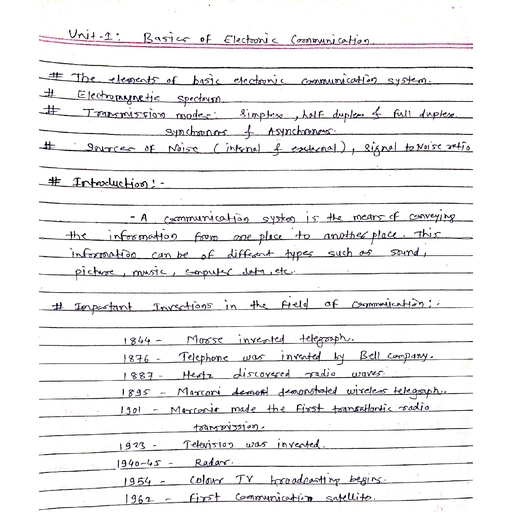
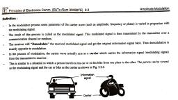
Basics of Electronic, , 1, , Communication, , Unit-I, Syllabus:, , spectrum, Transmission modes,, The elements of basic electronic communicatlon system. Electromagnetic, Signal to, Asynchronous, Sources of noise (Intemal and extemal),, Simplex, Duplex-fullhalf, Synchronous and, noise ratio., , 1.1, , Introductlon:, at a distance. A, electronics field. Telecommunication means communicating, The communication branch is the oldest branch of the, can be of different, from one place to the other. This information, communication system is the means of conveying the information, music, computer data etc., such as sound,, , picture,, , types, , and then, in the nineteenth century when the telegraph, telephone, The field of communication engineering started developing rapidly, and then colour TVs, the twentieth century when first the black and white, the radio were invented. The development was still faster in, cable TV, mobile telephones, , brought in use. Then came the age of satellite communication,, to understand, In order to understand the subject, it is necessary, etc., modulation, noise, demodulation, information theory, were, , The, , 1.2, , such, the basic concepts in communication engineering, , as,, , Importance of Electronic Communications, , Communication means the process of exchanging, , information. It is used for conveying thoughts,, , ideas and, , feelings to one another., , expressions,, being can be verbal, non-verbal, via body language,, has two main bariers namely distance and language., communication between human beings, facial, , The communication between human, The, , etc., , Out of them the distance problem is solved, Communication between humans, , After that the telegraph, The next step, , was, , was, , days by means of introducing long distance, , changed dramatically in the late nineteenth century, , invented in 1844 and the, , telephone in, , communication., , when electricity, , was discovered., , 1876., , 1895., introduction of radio. The first radio was demonstrated in, , Invention of radio, , was a, , some, , of communication field has continued, forward in the field of communications. The ovolution, Internet and cellular telephony has radically changed it., , huge leap, , since then and in recent times the, , Table 1.2.1 lists, , now a, , wnitten words etc., , the yoans in which they took place., important inventions in the communication field, alongwith, , Table 1.2.1: Important inventions in the fleld of communicatlon, Year, , Event, , 1844, , Morse invented telegraph, , 1876, , Telephone was invented by Bell company, , 1887, , Hertz discovered radio waves., , 1895, , Marconi demonstrated wireless telegraph.
Page 2 :
L, , Basics of Electronic Communicatinn, catilon, , Principles of Electronics Comm. (E&Tc./Sem 3/MSBTIB 1-2, Year, 1901, , transmission., transatlantic radio, Marconi made the first, , 1923, , Television was invented., , 1940-45 Radar, , O, , 1954, , Colour TV broadcasting begins., , 1962, , First communication satellite., , 1969, , Invention of the Internet, , 1975, , Personal computers, , 1983, , Cellular phones, , 1998, , HDTV, , use the electronic communication and they have increased our ability to share information and have become very, , important parts of our lives., Knowledge and information come pouring in from all the cormers of world due to the electronic communication means., This has, , changed our society from what it was to what it is now., , The key part of todays modera world is conmmunications because without electronic communications, we could not apply or use the, , available information in a timely way., , 1.2.1, , Types of Signals, , W-15, , MSBTE Questions, e, , efine 1, , Analog signal 2 Dgital signal, , (W-15,2 Marks, , Signals can be of three types:, , 1., , 1., , Analog signals., , 2., , Digital signals., , 3., , Baseband signals, , Analog signal:, Tt is the signal in which the signal magnitude vanes in a smooth fashion without any break with respect to time, as shown in, , Fig. 1.2.1(a)., , 2., , Digital signal:, Tt is the signal in which the signal magnitudes nas a COnstant ievel ror some period of time, then it changes suddenly to another, , constant level as shown in Fig. 1.2.1(6). The examples or digtal signal are binary signal, hexadecimal signal etc., *"*****g*******r*, , Magnitude, , (a) Analog slgnal, , ******"********| *********?, , *"******, , (b) Digltal signal, , www.w, , (L-24) Fig. 1.2.1: Types of signals
Page 3 :
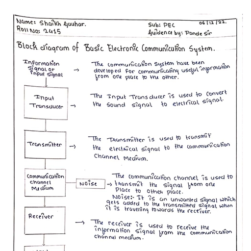
Principles of Electronics Comm. (E&Tc/Sem 3/MSBTE) 1:3, 3., , Basics ofElectronic Communication, , Baseband signal, The intormation or the input signal to a communication system can be analog i.e. sound, picture or it can be digital e.g. the computer, , data., , The electrical equivalent of this original information signal is known as the baseband signal., A baseband signal is thus obtained at the output of an input transducer as shown in Fig. 1.2.2., , Original Input, , Electrical equivalent, , Transducer, , slgnal, , (baseband signal), , D-1303)Fig. 1.2.2: Baseband signal, , The Elements of Basic Electronic Communication System:, , 1.3, , w-04, S-08, W-08, S-09, W-09, S-10,W-10, S-11, S-12, W.12, S-13,S-14, W-14,S-15, W-15.S-16.W-16,S-17,W-17, MSBTE Questions, a.1, , a.2, Q.3, Q.4, .5, , Draw the block diagram ofbasic communication system., , (W-04, S-08, W-08, S-09, W-09, S-10, W-10, 2 Marks), (S-11, S-14, 4 Marks), , Draw and explain block diagram of communication system., Draw a block diagram of communication system., Draw theblockdiagram ofcommunication system and explain., Expiain the basic block diagram ofcommunicationsystem., , (S-12, 2 Marks), , (W-12,4Marks), (S-13,4 Marks), , a.6 Draw the block diagram of communication system and state the function of each block, , (W-14, S-16, S-17,4 Marks), (S-15, 4 Mar, , a. 7, , Draw block diagram of basic electroniccommunication system. Describe its working principle., , a.8, , Draw the blockdiagramofbasicelectronig 6ommunication system and label it. Explain the concept of channel., W-15,4 Mare, W-16, 4 Marks), , a.9 Describe the blook diagramofbasic communicationsystem., a. 10 Draw and explain,block diagram ofelectroniccommunicationsystem, , (W-17,4Marks), , The block diagram of the simplest possible communication system is as shown in Fig. 1.3.1., As seen from the Fig. 1.3.1, the elements of a basic communication system are transmitter a communication medhum (channei) and, , the receiver., When the transmitted signal is travelling from the transmitter to the receiver over a communication channel. noise gets added to it, The elements of basic communication system, , are as, , follows, , 1., , Information or input signal, , Input transducer, , 3., , Transmier, , Communication channel or medium, , 5., , Noise, , Receiver, , 7., , Output transducer, , Information, , or input, signal, , Communication, , Input, transducer, , Transmitter, , Sound, picture, , Information, , speech, data, etc., , in the electrical, , ohannel, , Receiver, , or medium, , Noise, , Output, transducer, , Recovered, , Intormaton, , information in, electrioal torm, , in the ortginal, form, , form, D-1) Fig. 1.3.1 : Block diagram of the basle communication system
Page 4 :
Principles of Electronics Comm., (E&Tc/Sem, , Information or Input signal, , Basics of Electronic Communication, , 3/MSBTE) 1, , w, , caion systems have been developed for communicating useful information from one place to the otner., OTmation can be in the, form of asound signal like speech or music, or it can be in the form ot picuires, g, be data information, coming from a computer., , Can, , Inputtransducer:, he, , information in the form of, sound, picture or data signals cannot be transmitted as it 15., First it has to be converted, into a suitable electrical, signal. The input transducer block does this joo., The input transducers, commonly used in the communication systems are microphones, TY canora, , Transmitter:, The, , function of the transmitter block, is to, , In addition to that it, , transmitted signal., , convert the electrical, , increases the power level, , The transmitter consists of the, , of the, , equivalent of the information to a, , suitabie, , ronn., , signal., The power level should be increased in order to ncrease the range of, , electronic circuits such as amplifier, mixer, oscillator and power, ampiner, , Communication channel or medlum:, The, , communication channel, , is the, , path used for transmission of electronic signal from one place to the other. The communication, conducting wires, cables, optical fibre or free space. Depending on the type of communication medium, two types of, communication systems will exist. They are, medium, , can, , be, , Wired communication or line communication, Wireless communication or radio communication, 1., , Linecommunication:, The line communication systems, , use, , the communication mediums like the simple wires, , or, , cables or optical fibers., , The examples of such systems, are telegraph and telephone systems, cable T.V. etc., Due, , physical, distances., 2., , to, , connection from one point, , to the, , other, these systems, , cannot be, , used for the communication, , over, , long, , Radio communication, The radio, , communication systems, , use, , the free space, , as, , their communication medium., , They do not need the wires for sending, , the information from one place to the other., The radio or TV broadcasting, satellite communication are the examples of the wireless communication. These systems transmit, the signal using a transmitting antenna in the free space., , The transmitted signal is in the form of electromagnetic waves. A receiving antenna will pick up this signal and feed it to the, , receiver, Radio communication can be used for the long distance communication such as from one country to the other or even from one, planet to the other., , Noise, Noise is an unwanted electrical signal which gets added' to the transmited signal when it is travelling towards the receiver., Due to noise, the quality of the transmitted information will degrade. Once added, the noise cannot be separated out from the, , information.
Page 5 :
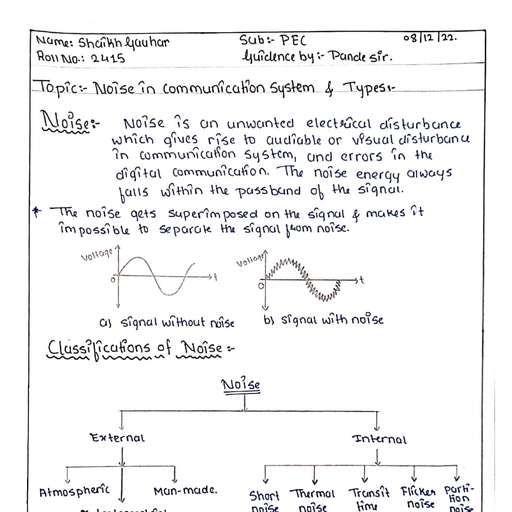
|2 Principles of Electronics Comm. (E&Te./Sem 3/MSBTE) 15, Hence noise is, , a, , Basics of Electronic Communication, , big problem in the communication systems. (Specially analog communication systems)., , The noise can be either natural or manmade. The sources of natural noise are lightning or radiation from the sun and stars etc., , The man made noise includes the noise produced by electrical igition systems of the automobiles, welding machines, electric motors, etc., , Eventhough noise cannot be completely eliminated, its effect can be reduced by using various techniques., , Recelver:, The process of reception is exactly the opposite process of transmission. The received signal is amplified, demodulated and converted, , into a suitable form., The receiver consists of electronic circuits like mixer, oscillator, detector, amplifier etc., , Output traneducers:, The output transducer converts the electrical signal at the output of the receiver back to the original form ie. sound or TV pictures, etc., , The typical examples of the output transducers are loud speakers, picture tubes, computer monitor etc., , Noise In Communication Systems and Types, , 1.4, , Definition:, Noise is, , an, , unwanted electrical disturbance which, , gives, , rise to audiable, , or, , visual disturbances in the communication systems, and, , errors in the digital communication. The noise energy always falls within the passband of the signal., , Fig., , 1.4.1 shows the effect of noise, , on, , the, , signal. Fig. 1.4.1(a) shows, , a, , clean, , signal, , without any noise and, , Fig., , 14.1(b) shows, , a, , signal mixed with noise., the, to, it, The noise gets superimposed on the signal and makes impossible separate, , Voltage, , Voltage, , signal from noise., , My, , ww, (a) Clean signal without, , nolse, , www, , (b) Signal with noise, , (D-1291)Fig. 14.1, , W-14. W-15.,S-16, , 1.4.1 Types of Nolse, MSBTE Questions, noise in communication system., Q. 1 State and explain the types of, , one of them, a. 2 List atleast four types of noise. Explain any, Noise can be divided into two broad categories, 1., , noise., External noise of uncorrelated, , 2., , Internal noise or correlated, , noise or fundamental noise., , (W-14, S-16, 4 Marks), , (W-15, 4 Marks)
Page 6 :
Basics of Electronic Communication, , Principles of Electronics Comm. (E&Tc./Sem 3/MSBTE) 1-6, The classification of noise sources is shown in, , Fig., , 1.4.2., , Noise, , Intemal, , Extemal, , Man-made, , Atmospherio, , Shot, , Themal, , nolse, , nolse, , Translt time, , Flioker, , Pardtion, , noise, , nolse, , noise, , Extratemestial, , D-1292)Fig. 1.4.2, , 1.4.2, , W-14. W-15. S-16, , External Noise:, , MSBTE Questions, C1State and explain the types ofnoise incommunication system., , (W-14, S-16, 4 Marka, , M-15,4 Marke, , o 2 ust adleastfour bypes ofnoice. Expeinanyone ofthem., Definition, , It is defined as the noise that is generated outside the devrice or circuit. As shown in Fig. 14.2, the external noise can be of three, , ypes, 1., 1., , Atmospheric noise, , 2., , Extraterrestrial and, , 3., , Man made noise, , Atmospheric nolse:, This type of noise gets, , produced within the Earth's atmosphere, , The common source of this type of noise is lightning., This type of noise is in the form of impulses or spikes which covers a wide frequency band typically upto, 30 MHz., The sputtering, cracking etc heard from the loud speakers of radio is due to atmospheric noise., This type of noise becomes insignificant above 30 MHz., , 2., , Extraterrestrial noise, This type of noise originates from the sources which exist outside the Earth's atmosphere. Hence this noise is also called as, deep space noise., The noise originating from the sun and the outer space is known as Extraterrestrial Noise. The extraterrestrial noise can be, sub-divided into two groups: (a) Solar noise (b) Cosmic noise. Our sun being a large body at very high temperanres radiates a, , lot of noise. The noise radiation from sun varies with the temperature changes on its surface., The temperature changes follow a cycle of 11 years hence the cycle of great electrical disturbances (noise) also repeats after, every 11 years., The cosmic noise comes from the stars. This is identical to the noise radiated by sun because stars also are large hot bodies., , This noise is called as black body noise or thermal noise and it is distributed uniformly over the entire sky. The noise also gets, originated from the center of our galaxy, other galaxies and special type of stars such as "Quasars" and "Pulsars"., , 3., , Man made noise, , (Industrlal noise), , The man made noise is generated due to the make and break process in a curront carrying circuit. The examples are the, , electrical motors, welding machines, ignition system of the automobiles, thyristorised high current circuits, fluorescent lights,, switching gears etc., , This type of noise is also called as industrial noise.
Page 7 :
Basics of Electronic Communication, , 2Principles ofElectronics Comm.(E&Te./Sem 3/MSBTE) 1-7, 1.4.3, , W-14. S-16, , Fundamental orInternal Noise, , MSBTE Qucstions, , State, , The fundamental sources of noise are within the electronic, , integral part, , W14S36,4Mar, , and explain tbe ypes ofnose in comumunicationsystem, of the, , physical, , nature of the material used for, , equipment. They, , are, , called fundamental, , sources, , because they, , are the, , making electronic components. This type of noise follows certain, , rules., , Therefore it can be eliminated by properly designing the electronic circuits and equipment., , 1.4.4 Types of Internal Nolse:, The internal (fundamental) noise sources produce different types of noise. They are as follows:, 1., , Thermal noise., , 2., , Shot noise., , 3., , Partition noise., , 4., , Flicker noise., , 5., , Transit time noise., , 6., , Avalanche noise., , 7., , Burst noise., , 1.4.5, , Slgnal to Nolse Ratio (S/N):, , In the communication systems the, , comparison of signal power with the noise power at the same point, , is, , important,, , to, , ensure, , that the, , noise at that point is not excessively large., , Definition:, It is defined as the ratio of signal power to the noise power at the same point., (1.4.1), , Where P,, , P, , =, , Signal power, , Noise power at the same point., values of S/N ratio range from about 10 dB to 90 dB., , signal to noise ratio is normaly expressed in dB and the typical, of noise., value of S/N ratio better the system performance in presence, , The, , (1.4.2), , SN (B) = 10 lo80 P,/P), , The powers can be expressed in terms, , of signal and noise, , Higher the, , voltages as follows:, , P,ndPWhere V, = Signal voltage and V, = Noise voltage., , .(1.4.3), , The signal to noise ratio in dB is given by,, , S/N, , 10losV201oo, , All the possible efforts are made to keep the signal to noise ratio as high as possible, under all the operating conditions., , (1.4.4)
Page 8 :
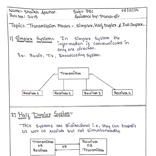
Basics of Electronic Communication, , 2 nciples of ElectronicsComm. (E&Tc./Sem ASBTE) 1-8, 1.5, , Transmission Modes:, Based on, , whether the given, , communication system, , communicates oniy, , in one, , direction or in both, , durections, the, , communio, ication, , Electronic communioation systems, , systems are classified as:, 1. Simplex systems., 2. Half duplex, 3. Full, , Bidirectional, (Duplex systems), , Unidirectional, , systems., , (Slmplex systems), , duplex systems., , Fig. 1.5.1 shows this classification., , Halt, , Full, , duplex systems, , duplex systems, , D-3Fig. 1.5.1: Types of electronic communications, 1.5.1, , Simplex Systems:, , W-12,, , S-13,, , S-14, W-14, S-16, , MSBTE Questions, a. 1, , Define Simpiex and duplex mode of alectronic Cormmunication, , (W-12, 4 Marks), , Q.2 Giveexamples ofsimplex and duplexcommunication system, Q.3 Define with suitable example Simplexand Duplex communication system, , (S-13, 2 Marke), (S-14, S-16,2 Marks), , .4 Definesimplex andhalfduplex systom with sketch., In these, transmit., , Another, , the information is communicated in, , systems, They cannot receive, , example, , (W-14, 2Marks), , only one direction. For example the radio or TV broadcasting systems can, , Transmitting, , of, , simplex communications is the information, transmitted by the telemetry system of a satellite to earth., The telemetry system transmits information about the, of the satellite such as its position or, temperature., , only, , ransmitter, , antenna, , Unidirectionat, flow of, , physical status, , information, , The simplex system are demonstrated in Fig. 1.5.2., , Receiver, , Receive, 2, , Receiver, 3, , D-4) Fig. 1.5.2 : Simplex system, , 1.5.2 Half Duplex Systems, , w-06, W-09, W-10, S-11,S-13, S-14, W-14, S-16. W-16, , MSBTE Questions, , Q.1 What is half duplex type of communication?3, , (W-06,W09, 1Mari), , Q:2 Explain neat sketchofhalf and fulduplex, , (W-10,4Marks), , Q 3 Define half duplex and full duplex type ofcommunication., Q.4, , (S-11,W-16, 2Marks), , Give examples of simplexand duplex communication system., , (S-13, 2 Marks), , Q.5 Define with suitable example::Simplexand Duplexcommunication system, a.6 Define simplex and halfduplex system with sketch., , (S-14, S-16,2 Marks), , (W-14, 2Marks), , These systems are bidirectional, ie. they can transmit as well as receive but not simultaneously., At a time these systems can either transmit or receive, for example a transreceiver or walky talky set., , The direction of, , communication, , will, , keep changing itself., , citizen band (CB) and amateur radio are half duplex system., , The radio, , communications such, , as, , those used in, , military,, , fire fighting
Page 9 :
Basics of Electronic Communication, , 2Principles ofElectronics Comm. (E&To./Sem 3/MSBTE) 1, , W-06, S-08, W-09, W-10. S-11. w-12. S-13. S-14. S-16. W-16, , 1.5.3 Full Duplex Systems, MSBTE Questions, , (W-06, 1 Mark), , 1 What is full duplex type of communication ?, , (s-08, W-09, 2 Marks), , a.2 With the help of sketch explain ftull duplex., , (W-10,4 Marks), (S-11, W-16, 2 Marks), , a. 3 Explatn neatsketch of halt and full duplex., a. 4 Define halfduplex and full duplex type of communicaton., , (W-12, 4 Marka), , Q.5 Define: Simplex and duplex mode of electronlc communication., a 6 Glve examples otsimplex and duplex communicatlon system., , (S-13, 2 Marke), , (S-14, 9-16,2 Merke), , 0.7 Define with euitable example:Simplexand Duplexcommunication system, , These are truly bidirectional systems as they alow the communication to take place in both the directions simultaneously., These systems can transmit as well as receive simultaneously, for example the telephone systems., The majority of electronic communication systems however are duplex in nature., , The best example of full duplex communication system is the telephone system., , Fig.1.5.3 illustrates the concept ofduplex communication., Bidirectional flow, of information, , Transmitter, , Transmitte, eceiver, , Communication link, , Receiver 2, , (D-5Fig. 1.5.3: Duplex communication, , S-04 W-09, , 1.5.4 Comparison of Half Duplex and Full Duplex Systems, MSBTE QuestionS, Q. 1 Define and compare half duplex and full duplex on following points, , 1 . Definition, , (S-04, W-092Mara, , 2. Sketch, , Parameter, , Half Duplex, , 1., , Definition, , Communication is two way but one at a time., , 2., , Examples Walky Talky, , 3., , Sketch, , Sr No., , Fall Duple, Communicadon is twO way., , Telephone, Refer Fig. 1.5.3, , Refer Fig. 1.5.2, , S-07. W-08. S-10,S-12 S-15, S-17, , 1.5.5 Comparison between Simplexand Duplex Systems, MSBTE Questions, , (S-07, 2 Marka), , a.1 Differentiate between simplex and duplex, , Q. 2, , Diferentiate between simplex and duplex mode of communication with the help of sketch, (W-08, S-12, 2 Marks), , Q.3 Compare simplex and full duplex on the basis of :, , 1 .Definition 2. Sketch, . 4 Differentiate between simplex and duplex mode of communication., Simplex, Sr. No.| Parameter, , 3., , Definition, , Communication is one way., , Examples, , Radio/TV broadcast, , Sketch, , Refer Pig. 1.5.2, , (S-10,S-17, 2 Marke), , (S-15, 4Marka), Duplex, ommunication is two way., , Telephone, Refer Fig. 1.5.3
Page 10 :
Basics of Electronic Communication, Comm. (E&Tc./Sem 3/MSBTE), Principles of Electronics, 1.6, Data Transmisslon, Data, , transmission means, , ransmission, , There, , 1-10, , of bits, the torm, which is in, data, of, the m o v e m e n t, to the other.., one computer, medium from, , between, , two o r more, , digital, , devices, , The data, , takes place oversome physical, , are, , two ways, , of transmitting the digital, 2., , data. They, , are, , Serial transmission, , 1. Parallel transmission, , 1.6.1, , Transmission Mode :, , Various modes, , of data transmission, , are, , shown in, , Fig., , 1.6.1., , Data transmisslon, , Serial, transmisslon, , Parallel, transmission, , Synchronous, , Asynchronous, , (G-1039)Fig. 1.6.1: Modes of data transmission, As seen from Fig. 1.6.1, serial transmission and parallel transmission are the two basic types of transmission. The serial transmission, is the most preferred mode of data transmission., The serial transmission is further classified into two types namely synchronous and asynchronous transmission., , 1.6.2 Parallel Transmission :, In paralel transmission of data, ll the bits of a byteare tranamited simultaneously on separate wires as shown in Fig. 1.6.2., This type of transmission requires mutiple wires for interconnecting the two devices., Parallel transmision is possible practically only if the two devices are close to each other due to the length and the mumber of wires, , required., For example parallel transmission takes place between a computer and its printer., , Wires oarrylng the blts, wmnwwnn, , 5, :, , www.w.e, , ransmitter, , Recelve, , (G-1040) Fig. 1.6.2: Parallel transmission of data
Page 11 :
42Principles of Electronics Comm. (E&To./Sem 3/MSBTE) 1-11, , Basics of Electronic Communication, , 1.6.3 Serial Transmission, In serial transmission, the bits of a byte are serially transmitted one by one as shown in Fig. 1.6.3., , The byte to be transmitted is first stored in a shift register. Then these bits are shifted from MSB to LSB bit by bit in synchronization, with the clock. Bits are shifted right [see Fig. 1.6.3] by one position per clock cycle., , The bit which falls out of the shift register is transmitted. Hence LSB is transmitted first and MSB is the last bit getting transmitted., For serial transmission only one wire is needed between the transmitter and the receiver. Hence serial transmission is preferred for, long distance data communication. This is the advantage of serial transmission over parallel transmission., The serial transmission has a serious drawback. As only one bit is transmitted per clock cycle, it requires a time corresponding to, 8-clock cycles to transmit one byte. (The parallel transmission needs only one clock cycle to transmit a byte). The time can be, , reduced by increasing the clock frequency, Single wire used for, , transmission, , - Shift register, , (At transmitter), , MSB, , LSB, , 1L S B, MSB, , (G-1041)Fig. 1.6.3: Serial transmission, 1.6.4 Types of Serial Transmission, There are three types of serial transmission. They are:, 1., , Synchronous data transmission., , 2., , Asynchronous data transmission, , 3., , Isosynchronous transmission, , 1.6.5 Asynchronous Transmission, In asynchronous transmission, the transmitter can begin the transmission of data bytes at any instant of time., , Only one byte is sent at a, , time. After sending one byte the next byte can be sent after an, , arbitrary time delay as shown in Fig., , 1.6.4., , between them on this account., The transmitter and receiver can operate at different clock frequencies. There is no synchronization, As the data transmission can commence at any instant, it becomes difficult for the receiver to understand the instant at which the byte, has been transmitted., , the receiver to receive the data, , To, , help, , Fig., , 1.6.4. The start bit is, , always, , "0" and, , Start, , Data, , bytes, , "start" and, , "stop", , bits, , are, , used alongwith each data byte, , as, , shown in, , stop bit is always "1"., , Stop, byt, , dledla time lo, , Data byte 1 Idle, , (G-1043)Fig. 1.6.4: Asynchronous transmission, The idle time in between the adjacent data bytes is not constant. The idle time is also called as the gaps between the data bytes., In the asynchronous transmission the timing of the signal is not important, instead intormation is received and translated by the, sender and receiver., patterns which are agreed upon by the, , As long as these patterns are being followed, the receiver can retrieve the information without any problem.
Page 12 :
Principles, , Why is it cailed asynchronous, Tis mechanism is called, , However within each, This, , means, , Basics of Electronic Communicatin, , ation, , of Electronics Comm. (E&To./Sem 3/MSBTE) 1-12, ?, , be synchronized., receiver do not have to, level the sender and, asynchronous because at the byte, stream., with the incoming bit, the receiver should still be synchronized, , as, , byte,, , that some synchronization is required only for the, , duration of single byte., , Response to the start and stop blts, When the receiver detects, , a start, , bits as they come in., bit, it will set a timer and begins counting, , After "n" bits, the receiver searches for the stop bit., As, So, , start bit., it detects the stop bit, it will wait until it detects the next, level but the bits, the meaning of asynchronous is actually asynchronous at the byte, soon as, , are, , still synchronized. So their durations are, , same., , Dlsadvantages of asynchronous transmisslon, 1., , Additional bits called start and stop bits are required to be used., , 2., , It is difficult to determine the sampling instants hence the timing error can take place., The start/stop bits and idle time makes the asynchronous transmission slow., , 3., , Advantages of asynchronous transmlssion:, 1, , Synchronization between the transmitter and receiver is not necessary, , 2., , It is possible to transmit signals from the sources having different bit rates., The transmission can commence as soon as the data byte to be transmitted becomes available., , 3., 4., , This mode of transmission is easy to implement., , 5., , It is a cheap scheme., , 6., , It is an effective scheme., , Application of asynchronous transmission:, The connection of a keyboard to a computer is an example of asynchronous transmission., , 1.6.6 Synchronous Transmission:, Synchronous transmission is carried out under the control of a common master clock. Here the bits which are being transmitted are, synchronized to a reference clock., , No start and stop bits are used instead the bytes are transmitted as a block in a continuous stream of bits as shown in Fig. 1.6.5. There, is an inter block idle time which is filled with idle characters., , One blook-, , IdleFlagData, , Data, , byte byte, , One blook, , Data Data, , byte 1de Flaobye byte, , Data, , byto, , (G-1045)Fig. 1.6.5: Synchronous transmission, The receivers operates at exactly the same clock frequency as that of transmitter as both are synchronized with each odher., This is essential for eror free reception of data. Flag is a sequence of fixed number of bits which is prefixed to each block as shown, in, , Fig. 1.6.5. Flag is useful in identifying the beginning of a block.
Page 13 :
Basics of Electronic Communication, , Principles of Electronics Comm. (E&Te./Sem3/MsBTE) 1-13, , In the synchronous transmission the bit stream to be transmitted is combined into longer "frames". A frame would contain more than, , one bytes., There is no gap between the successive frames. The receiver separates the bit stream into bytes for the purpose of decoding, Start and stop bits are not used. Instead bits are transmitted serialy one after the other., The grouping of these bits is responsibility of the receiver., , Advantages, speed of transmission is much higher than that of asynchronous transmission. This, , The, , 1., , is due to the absence of gaps between the data, , units and absence of start stop bits., , 2., , Start and stop bits are not needed any more., Timing errors are reduced due to synchronization., , 3, , Dleadvantages:, The timing is very, , 1., , important., , The accuracy of the received data is, , dependent entirely, , on, , the, , ability, , of the receiver to, , count, , the, , received bits accurately., The transmitter and receiver have to operate at the, , 2., , same, , clock, , frequency., , This, , makes the, proper synchronization which, , requires, , system complicated., , Application of synchronoustransmlssion, The synchronous transmission, due to its, , high speed is used for the data exchange from, , one, , computer to the other., , Synchronlzatlon, The, , 1.6.7, , byte synchronization is achieved at the data, , link, , layer level for the synchronous transmission, , between computers., , Transmission:, Comparison of Synchronous and Asynchronous, Table 1.6.1, Asynchronous transmissio, , Parameter, , Sr, , Synchronous, , transmission, , No., Needed, , Not needed, , 1., , Synchronization, , 2., , Start and Stop bits, , Used, , Gaps between data blocks, , Present, , Absent, , 3., 4., , Speed, , Low, , High, , Not used, , Communication between a computer and keyboard.| Communication between two computers., , 5., , 1.7, , Application, , MSBTE Questions, a. 1, , a.2, , S-11, W-11, S-14,, , The Electromagnetic Spectrum, frequency ranges ofthe following, , Explain electromagnetic spectrum and state the, 2. Voice frequency, 1. Audio frequency, 3. Microwave frequency 4 Fiber optic communication, Give the classification of RF spectrum, , electromagnetic, Q.3 Draw and explain the, , W-16, , spectrum., , (S-11, 4 Marks), , (W.11,4Marks), , (S-14,4 Marks)
Page 14 :
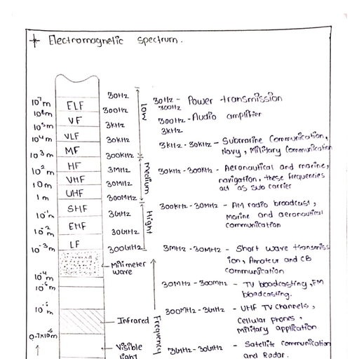
Principles, , of Electronics Comm., , 4, , (E&Tc./Sem 3/MSBE, , -14, , Basics of Electronic, , Describe electromagnetio spectrum, with diagram, The, information signal should be first, rst converted into an, , takes, ne, , place using the, electromagnetic waves., , electromagnetic, through space., he, , The, , frequency, , radio, , maghetic, , frequency (RF), , oscillate. They are sinusoidal and their frequency, of EM signal, , can, , Electromagnetic spectrum., The, , as, , (W-16, 4Marke, , electromagnetic signal before transmission because the, wireless, , waves consist of both electric and, , electromagnetic signals are also called, , n e EM, waves, , be very low, , or it can, , Communicat, cation, , fields. The, , electromagnetic, , transmis, snission, , waves can travel a, long, ong die, distance, , Waves., , is measured in Hz., , be extremely hign., , Tnis entire, , range of, , frequencies of EM waves is calledd, , ., , as, , electromagnetic spectrum consists of signals such as 50 Hz ine frequency and voice, , signals at the lower end., frequencies which are used for the two way communication reside at the, center of the EM, used for the, spectrum. These frequencies, applications such as radio or TV broadcasting as well., The radio, , The infrared and visible, , Fig., , are, , light are at the upper end of the EM spectrum., , 1.7.1 shows the entire, , electromagnetic spectrum., WAVELENGTH (Metres), X, , aalalElal, , X-rays,, gamma rays,, cosmic rays, etc., -Visible, , Millimeter, waves, , Low, , frequencies, , Infrared, , Medium, High, frequencies frequencies, , light, FREQUENCY, , D-19Fig. 1.7.1: Complete electromagnetic (EM) spectrum, , The short forms used in the EM, spectrum, , 1.7.1, , of Fig. 1.7.1 have the following meanings., , Different Frequency Bands:, , W-05, S-06, W-08, W-09, S-10, W-10,, , S-15, , MSBTE Questions, , 1Give the frequency band for Xray and infrared., Ans.Frequency band for X-rays is 3 x10Hzto3x10Hz, a.2 What are the frequency ranges of UHF and VHF frequency bands ?, a. 3State the frequency ranges of following, 2 Voice frequency, 1Audio frequency, 4. Very high frequency, 3 High frequenc, Q.4Write down differentfrequencies for following (frequency ranges), 1., , Voice frequency, , High frequency, , (W-05, 2Marks), , (S-06,W-08,S-10,2 Marks), , (W-09, W-10, 2 Marks)
Page 15 :
2 Principles of Electronics Comm. (E&Tc./Sem 3/MSBTE) 1-15, , Basics of Electronic Communication, , Table 1.7.1: Segments of the electromagnetic spectrum, , Sr. No, 1., , 1.7.2, , Frequency, , Name, , Extremely low frequencies (ELF), , Wavelength, 10' to 10 m, , 30-300 Hz, , 10 to 10 m, , 2., , Voice frequencies (VF), , 3, , Very low frequencies (VL, , 3-30 kHz, , 4., , Low frequencies (LF), , 30-300 kHz, , 5., , Medium frequencies (MF, , 300kHz- 3 MHz| 10 to 1o m, , High frequencies (HF), , 3-30 MHz, , 10 to 10 m, , 7., , Very high frequencies (VH, , 30-300 MHz, , 10 to 1 m, , 8., , Ultra high frequencies (UHF), , 300 MHz-3 GHz, , 1 to 10 m, , 9., , Super high frequencies (SHIF, , 300-3000Hz, , 10' to 10' m, , 10 to 10' m, , 3-30 GHz, , 10 to 10m, , 10 to10 m, , 10., , Extremely high frequencies (EHF) | 30-300 GHz, , 11., , Infrared, , 30 to 430THz, , 12., , Visible light, , 375-750 THz, , 0.7 to 10 um, 0.4 um to 0.8 um, , w-17, , Frequency and Wavelength, , MSBTE Questions, , O.1 Define, FrequencCy, , Wavelength, , Bandwidth, A ime period, , (W-17,4Marks), , In the EM spectrum, we have used frequency as well as wavelength in order to define various segments. So let us define these terms, and the relation between them., , Frequency:, Frequency is defined as the number of cycles of a waveform per second. It it expressed in hertz (Hz)., The units used to measure higher frequencies are kilohertz (kHz), Megahertz (MHz) and Gigahertz (GHz). Their relation with the, basic unit Hz is as follows:, 1 kHz, , =, , 1000 Hz, N, , 1 MHz = 1000 kHz = 1x 10° Hz., , 1GHz, , 1000 MHz =1x10 Hz., -1 cycle-, , D-17) Fig. 1.7.2: One cycle, , Wavelength (), Wavelength is, , defined as the distance travelled, , electromagnetic wave during the time of, Fig. 1.7.3 for the concept of wavelength., , one, , by, , - 1 wavelengthan, , cycle. Refer, , -1 wavelength, , (D-18) Fig.1.7.3 : Definition ofwavelength
Page 16 :
Principles of Electronics Comm. (E&Tc./Sem 3/MSBTE)116, E, , Basics of, , Electronic Communication, , Waves travel at the speed oflight in the free space or vaccum, their wavelength is given by,, , Speed oflight 3x10f m/s, , 1.7.1), , Frequency, , Hence, , 1.7.3, , wavelength decreases with increase in frequency., , EM, , Spectrum and Communication Applications8:, , W-12, , MSBTE Qucstions, , C1State applications of electronic communlcation., n, , the radio, , communication system, , the, , (W-12,4Marke, , frequencies ranging, , from, , a, , few kilohertz to many, , gigahertz, , all, , are, , being, , used for, , purposes., Let, , us see, , the, , various, , applications of various frequency bands., , The, , frequencies most commonly used in early days were from about 300 kHz, (MF). The frequencies in the range 30 kHz to 300 kHz are known as the low, The, , frequencies in, frequencies (HF), , the range 3 kHz to 30 kHz, , wil, , 30 MHz to 300 MHz and, , cover the, , frequency, , are, , called, , as, , very low, , to 3 MHz, , and, , frequencies (LR)., frequencies (VLF)., , were called as mediium, , frequencies, , On the, , range from 3 MHz to 30 MHz. Then very, , higher frequency side high, high frequency (VHF) from, , so on., , Table 1.7.2 gives you the details of entire, usable frequency spectrum and its applications., Table 1.7.2: The Radio Frequency Spectrum, , requency band, ., , 30 Hz-300 Hz., , Applicationas, 10 km to 10° km, , Power transmission., , 10 km to 100 km, , Audio applications., , 100 km to 10 km, , Submarine communications., , Extremely low frequencies ELF., , 300Hz -3 kHz., Voice frequencies (VF), 3 kHz-30 kHz., , 3., , Very low frequencies (VLF), 30 kHz -300 kHz., , Low frequencies (LF), , 10 km to 1 km., , Long waves., , AM radio broadcast, Marine and aeronautical, , Medium waves., , communications., , 100 m to 10Om, , 10 m to 1 m, , 300MHz-3 GHz, , Im to 10 cm., , Ultra high frequencies (UHF), , Microwaves., , 3 GHz-30 GHz(SHF), 30-300 GHz (EH, , 1.7.4, , Short-wave transmission, Amateur and CB communication., , Short waves., , Very high frequencies (VHF), , 10., , frequencies act, , Medium frequencies (MF), , 7. 30 MHz -300 MHz, , 9., , Aeronautical and marine, navigation, these, , as sub camiers., , 1 km to 100 m., , High frequencies (HF), , 8., , Navy. Military, , 300kHz -30 MHz, 3 MHz-30 MHz., , O., , communications., , TV broadcasting, FM, broadcasting, UHF TV, , channels,Cellular phones, Military applications., , 10 m to 10 m, , Satellite communication and Radar., , 10 m to 10" m, , Satellites and specialized radars., , Infrared Signals:, , The EM signals having frequencies above 300 GHz are not referred as radio waves.
Page 17 :
Basics of Electronic Communication, , Princlples of Electronics Comm.(E&Te/Sem 3/MSBTE) 1-17, , The signal occupying the range between 0.1 mm and 700 nanometers (nm) are called infrared signals., These are used in various special types of communications. Some of them are as follows:, 1., , In astronomy to detect stars and other heavenly bodies., , 2., , In the, , 3., , TV remote control., , 4., , Wireless keyboards and mouse., , guided weapon systems., , 1.7.5 Visible Light, Light is a special type of electromagnetic radiation. It has wavelength in the range of 0.4 to 0.8 um., Light is used for various kinds of communications., , Light waves can be modulated using the signal to be transmitted and transmitted through the glass fibers in the optical fiber, , communication system., Light signals can also be transmitted through free space. Laser is a type of light, which can be easily modulated with voice, video and, , data information., , 1.8, , Concept of Transmission Bandwidth, , S-08, S-09, W-11, S-13, S-17, W-17, , MSBTE Questions, , Q.1, Q.2, Q. 3, Q.4, , (S-08, S-13, 1 Mark), , Define, bandwidth, Definetransnissionbandwidth for analogcommunication, State and explain the concept oftransmission bandwidth, Define, Bandwidth, 1, reguency, , 3. Wavelength, , (s-09, 2 Marks), W-11, S-17,4 Marks), , (W-17,4 Marks), , Time period, , Bandwidth is defined as the portion of the electromagnetic spectrum occupied by a signal., We may also define the bandwidth as the frequency range over which an informmation signal is transmitted., Bandwidth is the difference between the upper and lower frequency limits of the signal., We already know different types of baseband signals such as voice signal, music signal, TV signal etc. Each of these signals will, have its own frequency range. This frequency range of a signal is known as its bandwidth., , For example, the range of music signal is 20 Hz to 15 kHz. Therefore as shown in Fig. 1.8.1 the bandwidth is (f,-f)., BW = f-f=15000 -20, = 14980 Hz., , Bandwidth, (BW), , = 20Hz, , 2, , 16kHz, , Frequenoy, , D-19)Fig. 1.8.1 Bandwidth ofmusie signal, The bandwidths of different signals are as listed in Table 1.8.1.
Page 18 :
Table 1.8.1, , Sr. No., , Type of the signal, , Bandwidth in Hz, , Range offrequency inHz, 300- 3400, , 3,100, , Music signal, , 20 15000, , 14,980, , 3., , TV signals (picture), , 0-5 MHz, , 4., , Digital data, , 1., , Voice, , 2, , signal (speech) for telephony, , 5 MHz, , 3,100, , 300- 3400, (If it is using the telephone line for its transmission)., , O, , Actually the required bandwidth in the data transmission depends on the rate at which the data is being transmitted., The BW increases with increase in the rate of data transmission, w.w, , 1.8.1, , AA, , Frequency Spectrum:, , reguency spectrum is the representation ofa signal in the frequency domain. It can be obtained by using either Fourier series or, Fourier transform., t, , consists of the, , amplitude and phase spectrums of the signal., frequency components present in the given signal., The, , 1.8.2, , The, , frequency spectrum indicates, , the, , amplitude and phase of various, , frequency spectrum enables us to analyze and synthesize a signal., How, , to, , obtaln BW of a, , The bandwidth of, , a, , The bandwidth of, , a, , Signal?, , signal which is to be transmitted can, series or Fourier transform, as shown in, Fig. 1.8.2., spectrum., , signal, , is defined, , Amplitude, , as, wwwwy, , be obtained, , by plotting the spectrum of the signal, , the difference between the maximum and minimum values, of, , help of Fourier, , frequencies present, , in the, , ****, , *ww*AR****wwwwwv, ***, , *ww., , with the, , w**, , **ww.wwwwwwwwwwww, , Mw, , ww., , wew, , wwwww.j, , e, , Frequency spectrum, ****, , *, , ***, , www, , www, , wwww.wMww., , Frequency, 20Hz, , -, , BW, , 20kHz, , D-20) Fig. 18.2: Frequency spectrum and bandwidth, , 1.8.3, , Effect of Pulse Width of Data on the BW:, , When data is, , to be, , transmitted, the bandwidth depends on the pulse width of data., , As the width of the data pulses which, Hence the, , are to, , be transmitted reduces, the bandwidth, , requirement increases., , signals having higher data rates need larger bandwidth., , What if the BW is less than, , required?, , BW of the communication channel has to be adequately large in order to preserve the shape of the transmited data signal. If BW is, , lessthan required, then signal distortion will take place.
Page 19 :
2Principles of Electronics Comm. (E&Tc/Sem 3/MSBTE)1-19, , Basics of Electronic Communicationn, , Review Questtone, Q.1, , Explain with neat schematic diagram the, , Q.2, , What is meant by analog and, , Q.3, , State and, , Q.4, , What is the difference between, , Q.5, , State and explain the, , Q.6, , Give the, , Q.7, , Write a note on: Electromagnetic spectrum and its applications in communication field., , Q.8, , Whet are the applications of following trequency bands in communication field, , system, , digital baseband signals?, , explain the concept of bandwidth., simplex, half duplex end duplex systems,, , also, , give, , 2., , UHF, , 3. SHF, , What is the ditference between wire communicatdon and wireess communication 7, , Q.10, , State the applications of wire and wireless communication., , a. 11, , Write note, , Q. 12, , Write a brief note on : Noise., , Q. 13, , What is electronic communication ?, , Q. 14, , Mention the, , a.15, , With the help of block diagram, explain the elements of communication, , O. 16, , Give simplex mode of electronic transmission, also give the example., , Q.17, , What is hatf and ftull duplex mode of data transmission ? Give, , Q. 18, , What is analog signal ?, , Q.19, , List the diferentfrequency bands and their oorreaponding trequene, , a. 20, , Give the concept of transmission bandwidth., , Q.22, , examples?, , applications of ocommunication system., , a.9, , .21, , its, , importance of communication., , ME, , 1., , operation of the basic communication, , on, , : The importanoe of channel bandwidth., , importance of communication system., , system, , examples, , Draw and explain the electromagnetc spectrum., Define frequency and wavelength., , 1.9, , MSBTE Questions and Answers:, , Q.1, , State the frequency ranges of the tollowing, 2. Voice trequenoy, , 1., , Audio frequency, , 3., , Microwave frequency4., , Fiber optüc, , Ans., Audio frequency range is 20 Hz to 20 kHz, 2. Voice frequency range is 300 Hz to 3000 Hz, , comvnunucaton, , (S-06, 2 Marka)
Page 20 :
Basics of Electronic Communication, , Principles of Electronics Comm. (E&Tc./Sem, Microwave, , 3., , Fiber optic, , 4, , frequency range is 300 MHz, , communication, , 3/MSBTE 1-20, , to 3 GHz., , to 750 GHz., range is 375 GHz, , ranges, and state the frequency, , Explain electromagnetic spectrum, 2. Voice frequency, 1. Audio frequency, communication., 4. Fiber optic, 3. Microwave frequency, , a.2, , Ans., , Refer Q. 1 for answer., , explain, , block, , a.3, , Draw and, , a.4, , Define with suitable, , (S-11,4Marka), , Summer 2014 [Total Marks -10, diagram, , of communication system., , example:Simplex and Duplex, , and, (Sections 1.5.1, 1.5.2, , (Sectlon 1.3), , communication, , (4 Marka), , system., , (2 Marka), , 1.5.3), , Draw and explain the electromagnetic spectrum., , Q.5, , of the following, , (4 Marke), , (Sectlon 1.7), , Winter 2014 [Total Marks 10]1, , a.6, Q.7, Q. 8, , Draw the block diagram of communication system and state the function of each block. (Section 1.3), , (4 Marka), , State and explain the types of noise in communication system. (Sectlons 1.4.1, 14.2 and 1.4.3), , (4 Marka), , Deine simplex and half duplex system with sketch. (Sections 1.5.1and 1.5.2), , (2 Marks), , Summer 2015, , [Total, , Marks, , 10], , Draw block diagram of basic electronic communication system. Describe its working principle., , a.9, , (Section 1.3), , (4 Marks), , a.10, , Diferentiate between simplex and duplex mode oft communication. (Sectlon 1.5.5), , (4 Marka), , Q.11, , Write down different frequencies for following (frequency ranges):, 1., , Voice frequency, , 2., , High frequency, , 3., , IR frequency, , 4., , Visible Spectrum (light) (Section 1.7.1), Winter 2015 [Total Marks 10, , (2 Marks), , (2 Marks), , Digital signal (Sectlon 1.2.1), , a. 12, , Define: 1. Analog signal 2., , a. 13, , and label it. Explain the concept of channel., Draw the block diagram of basic electronic communication system, , (4 Marks), , (Section 1.3), Q.14, , List atleast four types of noise. Explain any one of them. (Sections 1.4.1 and 1.4.2), , Summer2016 [Total, a.15, , Marks, , 10], , Define with suitable example: Simplex and Duplex communication system, (Sectlons 1.5.1, 1.5.2 and 1.5.3), , a. 16, , (4 Marks), , State and explain the types of noise in communication system. (Sections 1.4.1, 1.4.2 and 1.4.3), , (2 Marks), (4 Marke)
Page 21 :
Basics of Electronic Communication, , 2Principles of Electronics Comm. (E&To/Sem 3/MSBTE) 1-21, a.17, , Draw the block diagram of communication system and state the function of each block. (Sectlion 1.3), , (4 Marks), , Winter 2016 (Total Marks 10], a.18, , Describe the block iagram of basic communication system. (Sectlon 1.3), , (4 Marks), , a.19, , Define halt duplex and full duplex type of communication. (Sectlone 1.5.2 and 1.5.3), , (2 Marks), , a.20, , Describe electromagnetic spectrum, , with diagram.(Sectlon1.7), , (4 Marks), , a. 21, , Draw the block diagram of communication system and state the function of each block. (Sectlon 1.3), , (4 Marka), , Q. 22, , Compare simplex and full duplex on the basis of :, , Summer 2017 [Total Marks 10, , 1. Definition 2. Sketch., , (2 Marks), , (Section 1.5.5), a.23 State and explain the concept of transmissionbandwidth. (Sectlon 1.8), Winter 2017 [Total Marks, , 10], , a.24, , State the frequency range for audio trequency and volca frequency. (Q. 1 of Sectlon 1.9), , Q.25, , Define:, 1., , Frequency (Sectlon 1.7.2), , 2., , Bandwidth (Section 1.8), , 3., , Wavelength (Section 1.7.2), , 4., , Time period., , (4 Marks), , (2 Marks), , (4 Marks), , Ans., , 4., , Time period:, A time period is the time required to complete one cycle., , Q. 26, , Draw and explain block diagram of electronic communication system. (Section 1.3), , (4 Marks)
 Learn better on this topic