Page 1 :
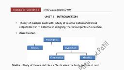
THEORY OF MACHINE-I, , UNIT 1:INTRODUCTION, UNIT 1: INTRODUCTION, , , , Theory of machine deals with: Study of relative motion and Forces, responsible for it. Essential in designing the various parts of a machine., , , , Classification, , Statics: Study of forces and their effects when the body (part) is at rest, Dynamics: The study of forces and their effects when the body (part) is in motion, Kinematics: The study of motion of a body or parts of machine without regard to, forces responsible for it. (position, displacement, rotation, speed, velocity, and, acceleration), Kinetics: The study of forces on systems when the body is in motion, What is machine ?, Machine is: Mechanism or combination of mechanism which Provide definite motion., A machine transmits and modifies mechanical energy into desired work. A machine is, a device which receives energy and transforms it into some useful work., Is this a Machine?, , Are these a Machine?, |Prof. N. R. Patil, Department of Mechanical Engineering, NKOCET, , 1
Page 2 :
THEORY OF MACHINE-I, , UNIT 1:INTRODUCTION, , Kinematic Link:, Rigid body: Does not undergo deformation/distortion when subjected to external, forces, Resistant body: These are rigid bodies & carry the external forces without, distortion, Semi-rigid body: These are flexible in nature & after loading they act as resistant, bodies (belt in tension, hydraulic system, spring system), Link/ kinematic link/ Element : Each part of a machine, which moves relative to, some other part is known as link or kinematic link or simply element OR, It is a member or combination of members of a mechanism, connecting other, member and having motion relative to them., Characteristics of a link:, It should be a resistant body and there should be relative motion between them., Types of links:, 1. Rigid link: Does not deform/distort when loaded, 2. Flexible link: Flexible but when loaded acts as resistant body, 3. Fluid link: act as resistant body when fluid is compressed, Classification: Based on the number of connection a link can have, 1. Binary link, , 2. Ternary link, , 3. Quaternary link, , No relative motion between the ends of link, , Types of Constrained motion, 1. Completely constrained motion: Motion in definite direction irrespective of, direction of force, |Prof. N. R. Patil, Department of Mechanical Engineering, NKOCET, , 2
Page 3 :
THEORY OF MACHINE-I, , UNIT 1:INTRODUCTION, , 2. Incompletely constrained motion: Motion in more than one direction & depend, on force direction, , 3. Successfully constrained motion: Motion between pair is made in one directionby external means i.e. by force, , , Foot step bearing (load restricts vertical motion), , , , IC engine (Piston can only reciprocate), , , , Engine valves (can only lift), , , , Pair / Kinematic pair:, , , , Joint of two links & one move relative to other, , , , Classification:, , 1. According to nature of contact, a. Lower pair: pair with surface/area contact (Nut & screw, shaft in a bearing.), b. Higher pair: pair with point/line contact (cam & follower, gears in mesh…), 2. According to nature of mechanical constraint, |Prof. N. R. Patil, Department of Mechanical Engineering, NKOCET, , 3
Page 4 :
THEORY OF MACHINE-I, , UNIT 1:INTRODUCTION, , a. Closed pair / Self closed : Elements of pair connected mechanically - Fig (a), Eg. Lower pairs, cam & follower, a. Unclosed pair / Forced closed : Elements of pair connected mechanically, due to external force (Gravity or spring force) - Fig (b), Eg. Higher pair (cam & follower), , 3. According to nature of relative motion, a. Sliding/prismatic pair: Two links of a pair have sliding motion relative to each, other (Fig-a). DOF=1, b. Turning/revolute pair: One elements of pair has turning or revolving motion, relative to other., , , Expressed by single coordinate θ & DOF=1, , c. Rolling/cylindrical pair: One elements of pair has rolling motion relative to other, (Fig-c), , d. Screw pair: Two links of a pair have turning as well as sliding motion (Fig-d), e. Spherical pair: One elements of pair has turning motion relative to other fixed, element (Fig-e), |Prof. N. R. Patil, Department of Mechanical Engineering, NKOCET, , 4
Page 5 :
THEORY OF MACHINE-I, , UNIT 1:INTRODUCTION, , Can you identify type of pair ?, , Types of joints, , , Defined on the basis of number of links joined at a point, , 1. Binary joint (2), 2. Ternary joint (3), 3. Quaternary joint (4), , Kinematics Chain, , , Assembly of no of links (kinematic pair) having definite motion relative to, other (Fig- a, b & c), |Prof. N. R. Patil, Department of Mechanical Engineering, NKOCET, , 5
Page 6 :
THEORY OF MACHINE-I, , UNIT 1:INTRODUCTION, , Non kinematic chain (Fig-d), Redundant Chain (Fig-e), , Mechanism, , , When one of the link of kinematic chain is fixed, it is mechanism, , , , Transmits and transforms motion, , , , Eg. Cam and follower, typewriter, , , , Simple mechanism – 4 links, , , , Compound mechanism – msm with more than 4 links is called compound msm, , |Prof. N. R. Patil, Department of Mechanical Engineering, NKOCET, , 6
Page 7 :
THEORY OF MACHINE-I, , , , UNIT 1:INTRODUCTION, , Classification of Kinematic Chain, , I. Four bar or quadratic chain, II. Single slider crank chain, III. Double slider crank chain, I. Four bar or quadratic chain, , , Consists 4 rigid links connected by pin joints, , , , Fixed link (AB) is frame of m/c, , , , Link which complete full revolution is a crank (AD), , , , Link opp to fixed link is coupler (DC), , , , Last link is a lever i.e. rocker or crank (CB), , , , To get continuous relative motion following condition must be satisfied, , , , , ∑(shortest & Longest) link length < ∑ (remaining 2 links), This is known as Grashof ’s law, , Inversion, , , When one link of K’Chain is fixed – Mechanism, , , , As many mechanism as number of links, , , , Method of obtaining different msm by fixing different links in a, , K’chain is, , known as- Inversion, I. Inversion of Four bar or quadratic chain, , , 1. Beam Engine (Crank and lever msm), , , , 2. Coupling rod of a Locomotive (Double crank msm), , , , 3. Watt’s Indicator mechanism (Double lever msm), , |Prof. N. R. Patil, Department of Mechanical Engineering, NKOCET, , 7
Page 8 :
THEORY OF MACHINE-I, , UNIT 1:INTRODUCTION, , 1. Beam Engine (Crank and lever msm), , , , Link 1: Cylinder and frame – fixed, Link 2: Crank – rotates @ A, Link 3:, Coupler/ connect crank and Lever, Link 4: Lever oscillates @ D, , , , Piston reciprocates, , , , Conversion of Rotary motion into Reciprocating motion, , 2. Coupling rod of a Locomotive (Double crank msm), , Consists 4 K’links & 4 turning pair, Link 1: Fixed, Pt A & B act as centre, Link 2 & 4: Crank having equal length, Link 3: Coupler to connect wheels, Transform rotary motion of one wheel to other, Application: Locomotive, 3. Watt’s Indicator mechanism (Double lever msm), |Prof. N. R. Patil, Department of Mechanical Engineering, NKOCET, , 8
Page 9 :
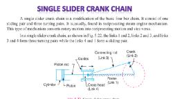
THEORY OF MACHINE-I, , UNIT 1:INTRODUCTION, , Consists of 4 K’links, Link 1: Fixed & forms turning pair, Link 2: (AC) Oscillates @ A, Link 3: (CE) lever 1,, end E trace approximate st. line , Link 4: (BFD) lever 2, one link, B & D – TP, Displacement of BFD-directly prop to pressure, Dashed line show displaced position, II. Single Slider Crank Chain, , , , Consists of 4 K’links, 3 turning pair & 1 sliding pair, , , , Converts reciprocating motion into rotary motion or vice-versa, , , , Eg. Steam engine, , , , Link 1: Frame of engine, Link 2: Crank turn @ pivot point, Link 3: Connecting, rod, connects piston & crank by turning pair, Link 4: Cross head constrained to, slide in the guide, Pairs: Link 1 & 4: Forms 1 sliding pair. Link 1&2, 2&3 and, 3&4: form 3 turning pair, , , , Reciprocating motion of cylinder converted into rotary motion of crank, , |Prof. N. R. Patil, Department of Mechanical Engineering, NKOCET, , 9
Page 10 :
THEORY OF MACHINE-I, , UNIT 1:INTRODUCTION, , Second inversion: Link 2 is fixed, When Link 2 is fixed it results in second inversion, Application :, 1. Withworth quick return msm, 2. Rotary engine, II.1. Withworth quick return msm, , II.2. Rotary engine (7 or 9 cylinders can be used), , Third inversion: Link 3 is fixed, When Link 3 is fixed it results in third inversion, Application :, 1. Oscillating cylinder engine, |Prof. N. R. Patil, Department of Mechanical Engineering, NKOCET, , 10
Page 11 :
THEORY OF MACHINE-I, , UNIT 1:INTRODUCTION, , 2. Crank and slotted lever msm, III. 1. Oscillating cylinder engine, , Link 1: Carry piston at its end, Link 2: Crank, Link 3: Coupler is fixed, Link 4: Cylinder, oscillates, III.2. Crank and slotted lever msm, , Link 1: Carry piston at its end, Link 2: Crank, Link 3: Coupler is fixed, Link 4: Cylinder, oscillates, , Fourth inversion: Link 4 is fixed, , |Prof. N. R. Patil, Department of Mechanical Engineering, NKOCET, , 11
Page 12 :
THEORY OF MACHINE-I, , UNIT 1:INTRODUCTION, , When Link 4 is fixed it results in fourth inversion, Application :, 1. Hand pump, Link 1: Follow translating motion, Link 2: Oscillates @ A & link 1 reciprocates, Link 3:, Pivoted at B & oscillates @ B, Link 4: Cylinder fixed, When L2 is moved up/down @, A, L1 slides in fixed cylinder, III. Double slider crank chain: Consists of two turning and two sliding pair, Inversions:, 1. First inversion : Link 1 is fixed (Application: Elliptical trammel), , P point on AB, trace ellipse, x=AP cos θ, So, cos θ= x/AP……….(i), y=BP sin θ, So, sin θ=y/BP…………(ii), , |Prof. N. R. Patil, Department of Mechanical Engineering, NKOCET, , 12
Page 13 :
THEORY OF MACHINE-I, , UNIT 1:INTRODUCTION, , Squaring and adding i & ii, sin2 θ+ cos2θ=1, Equation of Ellipse, If P is midpoint of AB, circle, AP=BP, x2+y2=AP2, Equation of circle, 2. Second inversion: Link 2 is fixed (Application: Scotch Yoke), , Link 1: Frame slides, Link 2: One of the Slider Fixed, Link 3: Acts as crank, Link 4:, Second slider slides, 3. Third inversion: Link 3 is fixed (Application: Oldham’s Coupling ), , |Prof. N. R. Patil, Department of Mechanical Engineering, NKOCET, , 13
Page 14 :
THEORY OF MACHINE-I, , UNIT 1:INTRODUCTION, , Degrees of Freedom (DOF) or Mobility, DOF of Body placed in a space as shown in Fig-a : a number of independent relative, motion (translational and rotational). a pair can have. Hence DOF = 6 (3 Translational, & 3 Rotational), DOF of Body placed in XY plane as shown in Fig-b: This body will have two, translational motions and one rotational motion. Hence DOF = 3, , Fig 1 (a-d) shows four Lower pair configuration., Fig-a, show single unconstrained link has 3 DOF. Fig-b, show 2 disconnected links, has 6 DOF. Fig-c, show 2 links welded together has 3 DOF. Fig-d, show Revolute, joint has 4 DOF, Hence, a lower-pair joint as shown in Fig-d, reduces the mobility of a mechanism, by two DOF, , Fig 2 shows Higher pair configuration, , |Prof. N. R. Patil, Department of Mechanical Engineering, NKOCET, , 14
Page 15 :
THEORY OF MACHINE-I, , UNIT 1:INTRODUCTION, , Fig-2 (a) show two elements before forming a pair having DOF=6. Fig-2 (b) show, two elements welded together having DOF=3. Fig-2 (c) show two elements forming a, high-pair having DOF=5. Hence, higher pair joint reduces the mobility of a, mechanism by one DOF., Grubler’s Criterion: If one link of a four bar kinematic chain is fixed, then the, number of movable links will be = (n-1). Hence total no. of DOF before connecting to, other link will be = 3 (n-1). Grubler gave the relation between number of links,, number of higher pair and number of lower pair as,, , m = 3(n – 1) – 2 j1 – j2, Where, n = no of links, j1 =no of lower pair link, j2 =no of higher pair link, Kutzbach Criterion: (modified Grublers equation): Considered higher pair (j2 = 0), , m = 3(n – 1) – 2 j1 – 0, m = 3(n – 1) – 2 j1, Mobility of various configurations of connected links, , (a) n = 3, j1 = 3, j2 = 0, m = 0;, , (b) n = 4, j1 = 4, j2 = 0, m = 1;, , (c) n = 4, j1 = 4, j2 = 0, m = 1;, , (d) n = 5, j1 = 5, j2 = 0, m = 2., , Find DOF of following, , |Prof. N. R. Patil, Department of Mechanical Engineering, NKOCET, , 15
Page 17 :
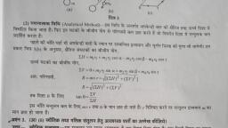
THEORY OF MACHINE-I, , UNIT 1:INTRODUCTION, , Since OC, OF & FC are fixed, = FD x FM, = (FN+ND) x (FN-MN), = FN2-ND2, = (FE2-NE2)-(ED2-NE2), = FE2 - ED2, = Constant, Hence point B traces straight line, Pantograph, , In this mechanism Link OB is pivoted at O, Length of Link AD=BC & AB=DC, which, forms parallelogram, Points O, D & E will be on straight line always, From similar, triangles OAD and OBE, OD/OE = AD/BE, For displaced position D’ & E’, OD/OE = OD′/OE′, From fig it is clear that DD’ is parallel to EE’, Hence, Point E will follow or copy path, of point D, Geneva mechanism: Driver: Link 2 (wheel) with a pin P & Driven: Link 3 (slotted, wheel). Transform a continuous rotation into an intermittent motion of the follower, |Prof. N. R. Patil, Department of Mechanical Engineering, NKOCET, , 17
Page 18 :
THEORY OF MACHINE-I, , UNIT 1:INTRODUCTION, , To make the engagement and disengagement as smooth as possible, the angle, between the crank r2 and the slot must be 90°, Number of slots needed is calculated by the relation given below, , Where, Number of slots = N and Angle = 𝜸, The minimum number of slots required to work is N min = 3., , |Prof. N. R. Patil, Department of Mechanical Engineering, NKOCET, , 18