Page 1 :
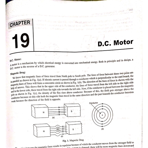
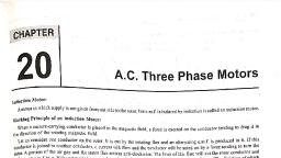
CHAPTER, , | 8 D.C. Generator, , DC. Generator: The energy can never be created nor destroyed but only its nature can be changed. The machine which converts, mechanical energy into electrical energy is called generator., , Principle of D.c. Generator: It works on the principle of Faraday’s Laws of electromagnetic induction i.e., whenever any, conductor or coil cuts magnetic lines of force, the e.m.f. will be induced in that conductor or coil.The direction of e.m.f., generated by generator can be found by applying Fleming’s Right Hand Rule (see magnetic chapter)., , , , , , b c c b, , , , , , , , , , , , , , , , , , , , a d qd, mo VN ae, , 90° 180° 270° 360°, , fs Fig. 1. Principle of D.C. generator, Working Principle of D.C. Generator: Earlier, we studied how the e.m.f. is induced in a generator, Imagine instead of, , conductor a coil “abcd” is rotated clock wise in between two magnetic poles N and S as shown in Fig. 2. Now, the coil side “ab”, is under the North pole while the coil side “ed” is under the south pole, as a result the e.m.f. is induced. This e.m.f. has got, different instantaneous values at different instants as shown in figure. When the coil sides will be in parallel with the field, there, will be no cutting of flux and hence no e.m.f. induced. After rotating 90° of the coil, it will cut maximum flux and hence, maximum e.m.f. will be induced. The direction of current is inward direction in b to a and outward in d to c. When the coil is, on the top ab and cd on the bottom, the direction of movement of the conductor and flux linking are parallel. Hence, the linkage, is zero hence no e.m.f. is induced. When the coil moved further ahead, the side of the coil cd under north pole will cut maximum, flux, the voltage induced will be maximum but in the reverse direction., , The direction of e.m.f. induced in the coil is always changed with the change of side of a coil and the e.m-f. will be induced, in the coil when coil cuts the lines of force. It is minimum to maximum in one direction and then change into another direction,, hence it is an alternating current inside the coil. Practically instead of one coil a number of coils are placed and e.m.f. induced, in the coils can be collected either by using slip rings or split rings (commutator)., , The E.M.F. collected by slip rings is alternating one so that machine is called A.C. generator or’alternator., The E.M.F. collected by split ring (commutator) is unidirectional (Direct current) so that machine is called D.C. generator., , yaa, , a a dq ad a @, dt 2 d, N s, | b e be 6 fe, Fig, 2. Working principle of D.C. generator, = 437, , , , , , , , , , , , , , , , Scanned with CamScanner, , |, :, |, |, |, |
Page 2 :
438 > Basic Electrical Engineering, , ay that the contact of one brush with one, to the magnetic lines of force, Thus,, directional current, known i, , Function of Split Ring: The split ting along with brushes are mounted in such a we, split ring changes over to the second split-ring when the plane of the coil is at right angle ini, i aaa . A . ‘ cycle el, we can say split-ring acts as an automatic reversing switch during each half cycle and BASS, , pulsating current,, , Parts of D.C. Generator or Machine,, , D.C. generators have the following components:, , 1. Yoke (body), 2. Pole, 3. Armature, 4. Commutator, 5. Brush, 6. Brush Holder, e ;, cover, 10. Cooling Fan, 11. Bearing, 12. Eye Bolt, 13, Bed Plate, 14. Terminal box,, , 7, Brush Lead, 8. Brush Rocker, 9. Eng, 15. Shaft and Pulley., , End Cover, Litting Eye Bolt, Hain Pa Ei, Yoxo, Armature Ny ”, in \ Inter Pole, , , , , , co, , / Cor Tt Tia), Bearing Nut & Bolt, End Cover, , Fig. 3. Parts of Generator, , , , , , 1. Yoke (Body): It is an outer part of the machine called Yoke or body and made of cast iron or cast steel. It has two main, { functions, one iS to hold all the other parts of the machine and second to provide magnetic path for the flow of magnetic, lines of force, because of this, yoke is always made of magnetic material,, Note: Small machines are made of cast iron but big machines are made of cast steel or rolled steel., 4 2. Field Pole: It is an internal part of the machine and is fitted with the body with the help of screws or nuts. Every machine, i has minimum two poles. It consists of two parts called pole cores and pole shoes, Pole cores are made of solid piece of, y cast iron, cast steel or laminated core but pole shoes are made of laminated core, The electro magnetic coil is fitted in the, pole core to provide magnetic lines of force and the function of pole shoes are to provide uniform flux., Note: Pole coils are made of copper winding wire or strip having a number of.turns. The number of holes in a machine, is always in even numbers i.e., 2, 4, 6, 8, etc., { 3. Armature: It is a revolving part of the machine and is made of laminated core having cylindrical shape. The thickness of, i laminated core is.0.35 to 0.6 mm dipped in insulated varnish to minimise the hysteresis and eddy current loss. The number”, i of slots are provided on its outer periphery in which suitable winding is done, re, Fypes of slot: There are three types of slots in the armature : :, /@ Open type slot: If the breadth of slot from top to bottom is same, it is called open type slot., {4) Semi closed type slot: If the breadth of slot is more in bottom than top, it is, , / called semi closed type slot. Insulation, (c) Closed type slot: If the upper portion of the slot is completely closed, it is called, closed type slot. This type of slot is used in A.C. induction machine. Commutator, , 4. Commutator: It is cylindrical shaped made of hard drawn copper. segments and, , each segment is insulated by thin layers of mica. Each segment h: raised portion, Known as Tiserfor connection ofccoil leads, It is fitted with one side of the armature, i aT iis Tontfon is to collect surzent ftom the of armature and converts it into, , DC, =, , , , , , , , , , ‘Commutator, f segments, , , , , , , , , Fig. 4. Commutator, , Scanned with CamScanner
Page 3 :
10., , 1., , 12,, , 13., , 14., 15., , . Brush Holder: It is hollow brass rod which holds the brush like lamp holder and suitable, , » Brush Rocker: It is a round plate fitted with brush holders and brushes. Its function is to, , D.C. Generator <439, , Brush: To collect the current from the commutator is known as brush. There are many types, , of brushes used in the machine depending upon the size of machine such as carbon brush,, copper brush and carbon copper brush ete., , spring is fixed with brush holder to provide spring pressure for brush. Spring pressure is, 0.1 to 0.25 kilo gram per square cm., , Brush Lead: It is a small piece of thick wire connected with brush. It is also called PigTail. Its function is to connect brush with the circuit., , , , adjust the position of brushes by Totating it., , . End Cover (End Plate): It is made of cast iron and fitted on both sides of the body of the Fig. 5. Brush Holder, , machine. Number of holes or cuts are provided for air circulation. There are two end covers known as front end cover and, back or rear end cover., , Note: The plate fitted towards commutator side is called front end plate or front end cover., , Cooling Fan: It is made of cast iron or aluminium and fitted with armature shaft opposite to commutator side. Its function is, to circulate air and keep the machine cool., , Bearing: It is fitted with side cover and its function is to minimise friction effect. There are so many types of bearing used, in machine according to its capacity., , (a) Bush-bearing: It is made of Gun-metal and used for small machine., (b) Ball-bearing: It is circular ring with number of balls and used for small and medium type machine., (c) Roller-bearing: It is circular ring with number of steel rollers and used for heavy duties machine., , Eye-Bolt: It is the upper most part of the machine, fitted at the top side of the yoke. It is used during shifting of, machine, The number of eye bolt depends upon the size and weight of the machine., , Terminal Box: Generally, it is fixed at one side of the machine having a number of terminals for armature and field, connection. ., , Base or Bed-Plate: It-is a lower part of the machine and used for providing proper foundation with surface., Shaft and pulley: A shaft is made of mild steel which carries the armature, commutator, fan and bearings., , The pulley is made of cast iron and is fixed on the shaft by a key or stud., , Types of Armature Windings:, , There are two types of armature windings:, , (1) Lap Winding, , (2) Wave Winding., , (1) Lap Winding: The winding used to carry more current and less voltage is called lap winding. In this winding the number, , of poles in the machine is equal to the number of parallel path for current. It is also called Parallel winding. The two ends, of any armature coil are connected to two adjacent commutator segments., , No. of path = No. of Poles ., , (2) Wave Winding: The winding used to carry more voltage and less current is called wave winding. In this winding the, , number of paths for current are always two, so there are only two carbon brushes irrespective of number of poles. The ends, of any coil are connected to commutator segments wide apart., , No. of path = 2, Comparison between Lap Winding and Wave Winding, , , , , , , , S.No. Lap Winding Wave Winding, 1. The parallel paths in the armature are equal in number There are only two parallel paths in respective, of poles. Pole (P) = Path (A) . ~ of number of poles. Path (A) = 2, 2. The number of brush sets is equal to the number of poles. The brush sets are used only two., 3. It is used for high current. It is used for low current., 4. It is used for low voltage machines. It is used for high voltage machine., , , , , , , , , , Scanned with CamScanner
Page 4 :
440 > Basic Electrical Engineering, , , , LF. Equation of Generator:, As we know that em.f., of generator is as under, , Let,, , P = Number of Poles, = Flux per pole in Weber, , Ecnerated in the generator is according to laws of Faraday’s maj, , E = E.MF. induced in generator armature conductor in Volt, , N = Speed of armature rotation in r.p.m. (N/60 in rp.s.), Z = Number of armature conductors, , A = Number of Parallel paths in armature winding., E.M.F. generated = E.M.F. generated in one parallel path., Cutting of flux per conductor in one revolution = OP Wo., , : a ~~ >, Cutting of flux per conductor in one second’=, , E.M.F, generated per conductor =, , “ Wb/sec., , SEN Volts, 60 é, , , , Z, , b PN, E.M.F. generated per path = SEN Volts, , 60 A, , In Wave Winding : The number of parallel paths are always two (A = 2) so,, , , , PN Z 6 ZPN, E.M.F. generated per path = OPN 2 Volts = —— Volts, 0 2 120, i In Lap Winding : The number of parallel paths are equal to number of poles so,, 1 :, j ZN, H E.M.F. generated per path = ae Volts, , Factors on which the e.m.f. of generator depends:, , a 1. number of conductors, , . speed of rotation, , . strength of the magnetic field, , + nature of the armature winding., , BWR, , | The relationship between e.m.f. and speed in a generator obtained by varying the speed of an un} generator while the field current is maintained constant. For each value of speed, the corresponding, When ploted (Speed vrs. generated e.m.f.), a straight line through the origin is obtaited as shown, , , , , , i As we know, the magnitude or the generated e.m.f. depends upon the rate of creating of lines of force., , It will depend upon:, , Relationship between e.m.f. and speed when the flux (9) is constant:, , loaded and separately excited, , e.m.f. generated is measured., , in Figure., e.m.f. (E) c speed (N), , ©), , Flux constant, , NOV, , , , Speed (N), , Fig. 6. EMF and Speed Curve, , Scanned with CamScanner, , gnetic induction, so the e.m.f. equation
Page 5 :
D.C. Generator <441, , Relationship between e.m.f, and field current when the speed (N) is constant:, If the speed is kept constant, the em.f. v;, variation of field current vrs, e.m.f. is sho, becomes less and less as the ficld current, iron of the magnetic circuit. As the speed i:, and hence the flux density B., , orE«B \, , aries as the field current is gradually changed. The Speed constant, wn, in figure. As is seen, the rate of increase of e.m.f., increases. This happens, owing to the saturation of the, 's constant, the e.m.f. is proportional to the flux per pole, , Now, the magnetising force H is proportional to the field current Ip, H=];, , - EMF.(EaB), , , , Hence, the curve relating e.m.f. and field current is of the same shape as that for B - H I, curve. If the field current is gradually reduced after reaching a maximum value, it is found that the Speed Current (a H), path of the curve is lying slightly above the ascending curve owing to the hysteresis. A few e.m.f., , due to residual flux is generated when I,= 0. This property is used in the self excited gencrators. Fig. 7., Example 1; (a) A four poles lap wound shunt generator has 800 armature conductors and runs at the speed of 400 r.p.m. Find, e.m.f. generated. If flux per pole is 0.05 Wb. . (NCVT-2010 W/M), , (8). Find e.m.f..generated when wound in Wave Winding., Solution: P=4, , , , Z = 800, N = 400 rp.m., A=4, > = 0.05 Wb, : oZN-: P, E.M.F, = —— x — Volts, (a) MF. 0 a VO, gn OOS E00 XA00 4 oc6'6 Vor, 60 4, (5) E.M.F. = g2N x 5 Vols, , _ 0.05 x 800 x 400, = 60, , Example 2: A 8 poles generator armature with 400 conductors runs at 1000 p.m. Find e.m.f. generated when flux per pole is, 0.06 Wb. ., , (a) Lap-wound (6) Wave-wound., Solution: (a) Lap-wound,, , x = = 533.3 Volts, , P=A=8, Z = 400, N = 1000 r.p.m., 6 = 0.06 Wb, ZN P, = fn ge? on, EMF. = “Go % % Volts, 2, ~5X 107 x 400x 1000 x S. 400 Volts, 60 8, (b) Wave-wound, oZN P, = —— x — Volts, EMF = 73% 5, 2, 6x 107 x 400 x 1000, 8 _ 1600 Volts |, 60 2 °, , Scanned with CamScanner