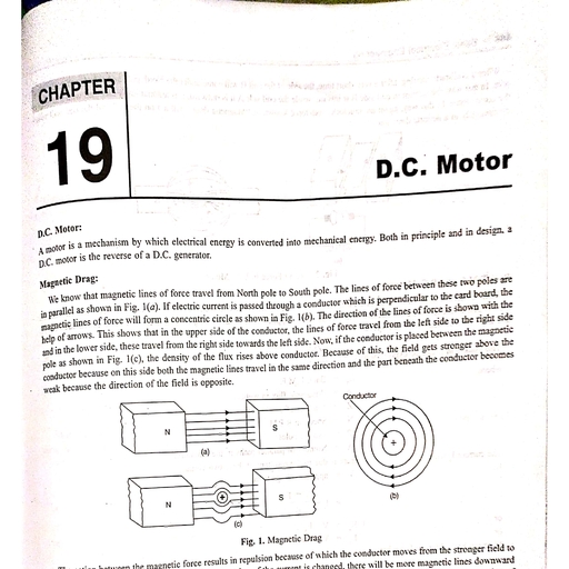
Page 1 :
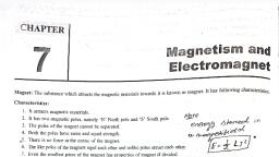
‘CHAPTER, , 20 A.C. Three Phase Motors, , -_—, , , , Induction Motor:, Amotor in which supply is not given from out side to the rotor, but e.m.f. is induced by induction is called an induction motor., working Principle of an Induction Motor:, , When a current-carrying conductor is ed ii ‘ i i it i, ihe direction of the rotating magnetic ae in the magnetic field, a force is exerted on the conductor tending to drag it n, , Let us consider one conductor on the rotor. It is cut by the rotating flux and an alternating e.m.f. is produced in it. If this, conductor is joined to another conductor, a current will flow and the conductor will be acted on by a force tending to turn the, rotor. A portion of the air gap and the stator flux rotates anti-clockwise. The lines of this flux will cut the rotor conductor and, induces an e.m.f. in it. If the rotor windings are short circuited, a current will flow in the rotor conductor (The direction of which, can be found by means of right hand rule). This current will set up another flux in the rotor conductor, which is clockwise, and, the flux lines will surround the rotor conductors. By combining the rotor and stator fluxes get the resultant flux , which actually, paned when the supply is given to stator and rotor is short circuited. The induced current strengthens the flux density on the right, , hand side and weakens it on the left hand side i.e., the flux in the gap would be distorted. Consequently a force is exerted over, the rotor tending to draft it in the direction of the field., , Main Parts of the Induction Motor:, There are two main parts of an induction motor., , 1. Stator 2. Rotor, , (1) Stator: The stator frame consists of a symmetrical and substantial casting, having feet cast integral with it. The stator core,, consists of high grade low hysteresis losses silicone steel laminations, is assembled in the frame under hydraulic pressure. The, thickness of the laminations is usually from 0.508 mm to 1.2 mm. Each lamination is duly insulated with varnish. Slots are cut, all around the periphery of the laminations for accommodation of windings. These slots may be semi-closed or open type., , (2) Rotor: It is a rotating part of the induction motor. These are of the following types., , (a) Single Squirrel Cage Rotor (6) Double Squirrel Cage Rotor, , (c) Deep Bar Squirrel Cage Rotor (d) Wound Rotor., , These are also built up of laminations of silicone steel and is cylindrical in shape. They also have slots in which windings, are placed., , Classification of A.C. Motor:, , , , , , , , Ae yee, Synchronous Motor canoe or Induction Motor, Three Phase Single Phase, | :, Squirrel Cage Motor Slip Ring Motor Double wate Cage Motor, 497, , Scanned with CamScanner
Page 2 :
498 > Basic Electrical Engineering, nett, , , , Rotating Magnetic Field in as Three Phase Motor:, Ina three phase moter, the, and the rotating fickd ths, , ach connected to a phase of a three pha, for aupplied with three ph, , * et, €, fe nrc three sets of coils inclined at 120° to one another, Se atl, , . ‘ phase ata, Juced, is for the rotation of the motor, Figure shows a three f, , SUP pty, , , , , , Fig. 1, Rotating Magnetic Field, , The magnetic field generated by one particular phase depends upon the current through the phase. If the current is zero, field, 3s zero. Hf the current is maximum the magnetic field is maximum, Fig, 1. shows a six pole stator. The winding Of pole aand, A’ are connected in phase A, the winding of pole b and B° are connected with phase B and the winding of pole C and C’ are, connected with phase C. As the six pole stator has two poles north and south, formed in cach phase. It is termed a two pole three, Phase stator. In a three phase stator the Phase difference between two windings is of 120°. When the current of phase A falls, from maximum value, the current of phase B increases and reaches its maximum value after one third of cycle as shown in, Fig. 1(4). When the current of phase B falls from maximum value, the current of phase C reaches its maximum value, and the, current of phase C reaches its maximum value after another one third of cycle. It appears that the value of flux keeps on changing., Due to the current of these three phases, three magnetic fields will be set up. As a result, a common magnetic field is set up in, the stator because the three currents always keep on fluctuating and their fields are also not stationary. It means that their north, and south poles also keep on changing. So, this kind of field is called rotating field. If a rotor is placed in between the rotating, magnetic field, it starts rotating in the same direction of rotating magnetic field., , Torque, Starting Torque and Running Torque in Induction Motor:, , Torque: When an induction motor is given a three phase supply,, Thus, the tuning effect acting on the rotor shaft is known as the torq, stator pole () and rotor power factor (cos 8)., , a rotating magnetic field is set up, which rotates the rotor., jue. The torque is proportional to rotor current (1), flux per, , Torque (T) = 1, x 9 * cos 8,, Where, T = Torque,, 6 = Flux,, 1, = Rotor current,, cos 8 = Rotor power factor, Starting Torque:, , It is the torque which is required to start the motor at load or at no load, It is available at the rotor shaft, and denoted by T., , =, , , , Where, T, = Starting torque, V = Supply voltage, R = Resistance/phase, X = Stand still reaction/phase = 2nFL., , Running Torque: Jt is the torque which is required to run the motor at normal speed with load. Itis also, , available at the rote, shaft,, , , , que (T) = ~~, Running Torque (T) =, Rv 4(SX,, , Scanned with CamScanner
Page 3 :
A.C, Three Phase Motors < 499, where, K = Constant, , S = Slip, , EE = Rotor emf. under Tunning condition, R= Rotor resistance / phase, , X = Rotor Treactance/phase, , short Notes on:, , a) Synchronous speed b —, ( (0) Rotor speed, (c) Slip (d) Slip frequency., , Synchronous Speed: The spee ;, hel and the sia of mae chee mngritle field ia’ ealled Whe synctronou? ee en =, oles. It is denoted by N, and its unit is r., ea s “p.m., , N= aS F, Where, N, = Synchronous speed, F = Supply frequency in ¢/s, P = Number of magnetic poles., , (b) Rotor Speed: The speed at which the rotor rotates is called the rotor speed or actual spced of the motor. It is denoted by, , N, and its unit is r-p.m. It is measured by a meter which is known as speedometer or tachometer. It is always less than the, synchronous speed., , (c) Slip: The difference between the synchronous speed and the rotor speed is called th, , e slip. It is denoted by S and is, calculated as a percentage. », , , , . Synchronous speed — Rotor speed, Slip % = =, * 100, line Synchronous speed, Ns-N, w= = x100, or 8% Ns, (@ Slip Frequency: It is the frequency of the rotor e.m.f. when running with slips, It is denoted by f,f., g=3, f, or f=Sxf, , Where, S = Slip, f, = Slip frequency, f = Supply frequency, , Example 1: An 8 pole alternator runs at 750 r.p.m. and supplies power to a 6 pole induction motor which has a full load slip, of 3%. Find the full load speed of the induction motor?, , Solution: Number of poles of the alternator = 8, Speed = 750 r.p.in., , _ PxN _8x750 _ 50 cl, Frequency (f) = 2 120 7 c/s, Supply frequency = 50 c/s, , Now the slip = 3% is given = 0.03, 120 F s 120 50 = 1000 rp.m., P 6, , Rotor Speed (Nr) = N, (1-8), = 1000 (1 - 0,03), = 1000 x 0.97 = 970 rpm., , The full Joad speed of the jnduction motor = 970 np.m., , N=, , , , Scanned with CamScanner
Page 4 :
500 > Basic Electrical Engineering, , Relation between ‘Torque and Slip;, , adueed, Hruna at AYACHHONOUA Apecd,, wapeod, there ino telitive, jog in parallel fo the rtatog, ants Indueed de the rotor The rotor, flotlon, Thin cates the ipecd, would be no alip, no current, , When a three phase supply is given to a stator of the motor, a rotating magnetie Held Is pr ‘, When the motor is untoaded, it rans at nearly synchronous speed. the rotor fins at aynehront mi, velocity between the rotor speed and the rotating magnetic field speed, Hmeans thatthe rotor iy en, field, At this stage the stator (ux will not cut the rotor windings and so there will he noe,, Will then tend to stop. When there is no Load on the motor, there are Lossex die to bearings and alr :, of the rotor slow down from synehronous speed, It means that if there is no Induced cant, there, and so no torque., , , , , , , , When the load is put on the motor, the speed decreases and slip increases, The routing magnetic held ats SU Mle ror, windings and the rotor current is increased resulting in increase of stip and, thus, greater Lone in produced,, Torque = Slip, Now, the rotor runs at a speed which enables it to develop a torque required to meet the |, of the rotor equals to the resistance of the rotor and this is the stage of maximum torque,, , oad, Ata certain specd, the reactance, , , , In brief, when the motor is loaded, the torque increases if the slip increases,, , , , Construction and Working Principle of A.C, Three Phase Squirrel Cage Induction Motor:, , Construction: There are two main parts of A.C, three phase squirrel cage induction motor., , 1, Stator 2, Rotor,, , The other common parts are shown in Fig 4. a . ., , 1, Stator: The stator frame consists of a symmetrical and substantial casting, having feet cast integral with it, Hels 0 stationary, part of the motor. The stator core, consists of high grade low hysteresis losses silicon steel laminations, is uss bled in the frame, under hydraulic pressure. The thickness of the laminations is usually from 0.508 mm to 1.2mm, Eaeh liminations duly insulated, with varnish slots are cut all around the periphery of the lamination for accommodation of windings, These slots may be seni, closed or open type. Three phase winding is done in these slots for two, four, and six poles ete, depending upon the speed, required. The speed increases as the number of poles decreases., , , , , , , , , , , , , , , , , , , , , , , , Fig. 2. Stator Fig. 3. Rotor, , , , 2. Rotor: It is a rotating part of the motor, It is also made up of laminations of silicone steel and is cylindrical in ghape, There, are number of closed slots in which copper or aluminium bars are placed. The ends of the bars are riveted and welded to solid, metallic rings at both the ends. The arrangement resembles a cage of a squirrel and hence it is called a squirrel cage rotor,, , , , , , , , , , , , Eye hole outer, Stator wind!, Fan cover Bolt bearing or winding, 1 eae, coupling, <0, Pulloy, J bearing Bearing Front ond cover, Fan End Coupline coupling, , ri, coupling Cover Base plate, , Fig. 4. Parts of Squirrel Cage Induction Motor, , Scanned with CamScanner
Page 5 :
A.C, Three Phase Motors < 501, , , , i inciple: Stator is connecte, sptking Princip has nected to three phase s 1 . i, wor induced in the ce phase supply. The rotating magnetic field is produced in #, , rs and an eT rin fi, mete rotor windings, which produces its out j a retell Sait set. 0 Dee Oia aa —_, , Q Sad ee cae nae agnetic field. These fic sethe, ‘ait field according tq Lenz s Law, This results in tuming an - sas ne hei, rotation of the field, tending to cateh it up, ‘nutuming the rotor in the direction, : ~ em oi, , he stator. It cuts the, he small resistance, , , , , , , ati ¢ of the motor is les ., The sta anes Ts less, but it takes high i ., , ri ——s h starting cu, of starting: ' gc ren ethene, Advantages: Following are the advantages:, 1. Cost is less. ~, 2. Ie requires less repairs and maintenancex, 3, Construction is simple.+~, 4, Starting is easy. ae =, 5, Speed almost constant., , 3 Phase, AC Supply, , , , : This motor is i A : i - 7, ‘Uses: ‘This 01 ‘ —_ in lathe machine, drill machine, printing press, tube-well, grinder etc., Construction and working principle of a A.C. three phase slipring motor. Its characteristics, advantages, disadvantages and, uses: :, Construction: The stator of the slipring motor is the same as that of a squirrel cage induction motor. The three phase winding, is placed in the stator~, Rotor: The rotor of slipring motor has wound rotor which carries three phase windings. The number of poles are equal to, the number of stator poles. The windings are connected in Star, and their three free ends are connected to an external rheostat, through three sliprings mounted’ on the shaft. These sliprings are insulated from each other and from the rotor shaft. This type, of rotor is also known as wound rotor as shown in Fig 6.°~, Working Principle: When three phase supply is given to the stator, a rotating magnetic field is produced in the stator., , But resistances, connected in star are connected to the rotor circuit of the motor. This resistance reduces the starting current, as shown in Fig 7. Because of rotating magnetic field, e.m.f. is produced in the rotor winding due to induction. In this way,, assoon as the circuit of rotor winding completes, current starts flowing in it and rotor also produces its own magnetic field., Two magnetic fields are produced, one due to the stator and the other due to the rotor. As a result, the rotor gets torque, and it tends to rotate in the direction of magnetic field. As the motor speeds.up, resistances in the rotor circuit is cut step, by step and finally the rotor winding is short circuited, and motor runs at its own speed., , hy, , , , , , , , tj, a Stator, , , , bs, Fig. 7. Three Phase Motor, , Fig. 6. Rotor, , The starting torque of the slipring motor is high, starting current low and power factor is high. Large slipring motors are, designed to have brush lifting and short circuiting device., , Advantages: Following are the advantages:, , 1. It has a high starting torque., , 3. It has a high power factor., , Disadvantages: Following are the disadvantages:, , 1. It is costly., , 3. It has a high copper loss., , Uses: It is used where high s, , 2. It draws low starting current., 4, Speed can be controlled., , 2, It requires more maintenance., 4. It cannot be used everywhere., tarting torque is required as in centrifugal pumps, elevators etc., , Double Squirrel Cage Induction Motor and Its Uses:, The stator of the motor is the same as that of an ordinary squirrel cage induction motor. But the construction of the rotor is, , different i.e., the rotor has two separate squirrel cages, one inside the other as shown in Fig 8. The outer one is of high resistance, , Scanned with CamScanner