Page 1 :
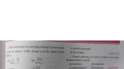
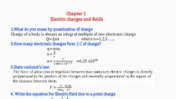
Chapter 2, Electrostatic Potential and Capacitance, Electrostatic Potential Energy, Electrostatic potential energy difference between two points, Electric potential energy difference between two points in an electric field ,, can be defined as the work done by an external force in moving (without, accelerating) charge q from one point to another in the electric field ., P, , ∆U = UP − UR = − ∫R F . dr, , • The work done by an electrostatic field in moving a charge from one, point to another depends only on the initial and the final points and is, independent of the path taken to go from one point to the other., Electrostatic Potential Energy at a point, Electric potential energy at a point P in an electric field is defined as the, work done by the external force in bringing the charge q from infinity to, that point., UP∞ = UP − U∞ = UP − 0 = UP, 𝐏, , 𝐔𝐏 =− ∫∞ 𝐅 . 𝐝𝐫, , downloaded from HSS REPORTER
Page 2 :
Electrostatic Potential (V), V=, , W, q, , W=qV, Unit of potential is J/C or volt (V), Electrostatic Potential between two points, Electrostatic Potential difference between two points in an electric field is, the work done by an external force in bringing a unit positive charge from, one point to other in that field., W, VP − VR = RP, q, , P, , VP − VR =, , − ∫R F .dr, q, , F=qE, P, , VP − VR =, , 𝐕𝐏 − 𝐕𝐑 =, , 𝐏, − ∫𝐑 𝐄, , − ∫R qE .dr, q, , . 𝐝𝐫, , Electrostatic Potential at a point P, Electrostatic Potential at a point P in an electric field is the work done by an, external force in bringing a unit positive charge from infinity to that point., 𝐏, , 𝐕𝐏 = − ∫∞ 𝐄 . 𝐝𝐫, Potential due to a Point Charge, , downloaded from HSS REPORTER
Page 3 :
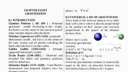
Variation of potential V with r and Electric field with r for a point charge Q, , Example, (a) Calculate the potential at a point P due to a charge of 4 × 10⁻⁷ C,located, 9 cm away, (b) Hence obtain the work done in bringing a charge of 2 × 10⁻⁹ C from, infinity to the point P. Does the answer depend on the path along which, the charge is brought?, (a), , V=, , 1, , 𝑄, , 4πε0 𝑟, 9, , = 9 × 10 x, , 4 𝑥 10−7, 0.09, , 𝟒, , V = 𝟒 𝒙 𝟏𝟎 V, (b) W= qV, = 2 𝑥 10−9 x 4 𝑥 104, W = 𝟖 𝒙 𝟏𝟎−𝟓 J, No, work done will be path independent. Any arbitrary infinitesimal path, can be resolved into two perpendicular displacements: One along r and, another perpendicular to r. The work done corresponding to the later will be, zero., downloaded from HSS REPORTER
Page 6 :
Potential due to a uniformly charged spherical shell, , a)The potential at a distance r, from the shell ,where r≥ R, (R-radius of sphere), For a uniformly charged spherical shell, the electric field outside the shell is, as if the entire charge is concentrated at the centre, 𝟏, , 𝐪, , V= 𝟒𝛑𝛆, , 𝟎, , 𝐫, , (r≥ R), , b) Inside the shell, Inside the shell the electric field is zero. This implies that the potential is, constant inside the shell ,which is equal to the value of potential at the, surface, 𝟏, , V= 𝟒𝛑𝛆, , 𝐪, , 𝟎, , 𝐑, , Example, Two charges 3 𝑥 10−8 C and –2 𝑥 10−8 C are located 15 cm apart. At what, point on the line joining the two charges is the electric potential zero? Take, the potential at infinity to be zero., Let P lies between O and A at a distance x from O,, , Potential at P due to charge 3 𝑥 10−8 C, 𝑉1 =, , 1, , 3 𝑥 10−8, , 4πε0, , 𝑥, , Potential at P due to charge −2 𝑥 10−8 C, 𝑉2 =, , 1, , −2 𝑥 10−8, , 4πε0, , 15−x, , downloaded from HSS REPORTER
Page 7 :
Total potential at P , V=𝑉1 + 𝑉2 =0, 1, , 3 𝑥 10−8, , 4πε0, , 𝑥, , 1, 4πε0, , [, , −, , 1, , 2 𝑥 10−8, , 4πε0, , 15−x, , 3 𝑥 10−8, , 2 𝑥 10−8, , −, , 𝑥, , [, , 3, , 15−x, , −, , x, 3, x, , =, , 2, 15−𝑥, , =0, , ] =0, , ] =0, , 2, 15−𝑥, , 45-3x=2x, 45=5x, , x=9cm, If P lies on the extended line OA,, , 1, , 3 𝑥 10−8, , 4πε0, , 𝑥, , 3, x, , 1, , 2 𝑥 10−8, , 4πε0, , x−15, , =, , =0, , 2, 𝑥−15, , 3x-45=2x, x=45cm, Thus, electric potential is zero at 9 cm and 45 cm away from the positive, charge on the side of the negative charge., , Equipotential Surfaces, An equipotential surface is a surface with a constant value of potential at all, points on the surface., • As there is no potential difference between any two points on an, equipotential surface, no work is required to move a test charge on the, surface., • For any charge configuration, equipotential surface through a point is, normal to the electric field at that point, downloaded from HSS REPORTER
Page 8 :
Equipotential surfaces for a single point charge, For a single charge q, the potential is, 1 q, V=, 4πε0 r, , V is a constant if r is constant ., Thus, equipotential surfaces of a single point charge are concentric spherical, surfaces centred at the charge., , Equipotential surfaces for a uniform electric field., , Equipotential surfaces for a dipole, , Equipotential surfaces for two identical positive charges., , downloaded from HSS REPORTER
Page 9 :
Relation between electric field and potential, , downloaded from HSS REPORTER
Page 10 :
b)For a system of three charges, , downloaded from HSS REPORTER
Page 11 :
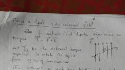
Potential energy of a dipole in an external field, , Electrostatics of conductors, 1.Inside a conductor, electrostatic field is zero, A conductor has free electrons. In the static situation, the free charges have, so distributed themselves that the electric field is zero everywhere inside., 2. At the surface of a charged conductor, electrostatic field must be normal, to the surface at every point., downloaded from HSS REPORTER
Page 12 :
3. The interior of a conductor can have no excess charge in the static, situation., 4. Electrostatic potential is constant throughout the volume of the, conductor and has the same value (as inside) on its surface., 5.Electric field at the surface of a charged conductor E =, , σ, ε0, , 6.Electrostatic shielding, The electric field inside a cavity of any conductor is zero. This is known as, electrostatic shielding. All charges reside only on the outer surface of a, conductor with cavity., The effect can be made use of in protecting sensitive instruments from, outside electrical influence., Why it is safer to be inside a car during lightning?, Due to Electrostatic shielding, electricfield E=0 inside the car., So it is safer to sit inside a car than standing outside during lightening., , Dielectrics and polarisation, Dielectrics, Dielectrics are non-conducting substances. In contrast to conductors, the, Dielectric substances may be made of polar or non polar molecules., , downloaded from HSS REPORTER
Page 13 :
Non polar molecules, , In a non-polar molecule, the centres of positive and negative charges, coincide. The molecule then has no permanent (or intrinsic) dipole moment., Eg: oxygen (O2 ) , hydrogen (H2 ), In an external electric field, the positive and negative charges of a nonpolar, molecule are displaced in opposite directions. The non-polar molecule thus, develops an induced dipole moment. The dielectric is said to be polarised by, the external field, , Polar molecules, , In polar molecules, the centres of positive and negative charges are, separated (even when there is no external field). Such molecules have a, permanent dipole moment., Eg: HCl , H2 O, In the absence of any external field, the different permanent dipoles are, oriented randomly ; so the total dipole moment is zero. When an external, field is applied, the individual dipole moments tend to align with the field. A, dielectric with polar molecules also develops a net dipole moment in an, external field., , Polarisation(P), The dipole moment per unit volume is called polarisation ., For linear isotropic dielectrics,, , 𝐏 = 𝛘𝐞 𝐄, where χe is the electric susceptibility of the dielectric medium., downloaded from HSS REPORTER
Page 14 :
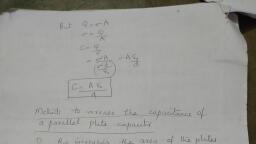
Capacitor, A capacitor is a system of two conductors separated by an insulator., Capacitor is a charge storing device., , Capacitance, The potential difference, V ( V = V1 - V2 ) between the two is proportional to, the charge , Q., Q∝V, Q=CV, , 𝐂=, , 𝐐, 𝐕, , The constant C is called the capacitance of the capacitor., C is independent of Q or V., The capacitance C depends only on the geometrical configuration (shape,, size, separation) of the system of two conductors ., SI unit of capacitance is farad., 1 farad =1 coulomb volt −1, 1 F = 1 C V −1, Other units are,, 1 μF = 10 -6 F , 1 nF = 10 -9 F , 1 pF = 10-12 F, etc., , Symbol of capacitor, Fixed capacitance, , • C=, , Q, V, , Variable capacitance, , . For large C, V is small for a given Q. This means a capacitor, , with large capacitance can hold large amount of charge Q at a relatively, small V, • High potential difference implies strong electric field around the, conductors. A strong electric field can ionise the surrounding air and, accelerate the charges so produced to the oppositely charged plates,, thereby neutralising the charge on the capacitor plates, at least partly., downloaded from HSS REPORTER
Page 15 :
• The maximum electric field that a dielectric medium can withstand, without break-down (of its insulating property) is called its dielectric, strength; for air it is about 3 × 10⁶ V𝑚−1, , The parallel plate capacitor, A parallel plate capacitor consists of two large plane parallel conducting, plates separated by a small distance., , Capacitance of a parallel plate capacitor, , Capacitance can be increased,, • By increasing the area of the plates., • By decreasing the distance between the plates., • By introducing a dielectric medium between the plates., , Effect of dielectric on capacitance, The capacitance of a parallel plate capacitor when the medium between the, plates is air,, Cair =, , ε0 A, d, , When dielectric medium of dielectric constant K is placed between the, plates, the capacitance ,, Cmed =, , Kε0 A, d, , The capacitance increases K times, where K is the dielectric constant., , 𝐂𝐦𝐞𝐝 =K 𝐂𝐚𝐢𝐫, downloaded from HSS REPORTER
Page 17 :
eg:-, , If C=1μF, C′ =, , C, n, , =, , n=10, 1μF, , 10, , = 0. 1μF, , The effective capacitance decreases when capacitors are connected in series., In series combination the effective capacitance will be smaller than the, smallest among individual capacitors., , Example, Find the effective capacitance of the combination., , 1, C, 1, C, , =, =, , C=, , 1, , +, , C1, 1, , 2F, 10F, 8, , +, , 1, C2, 1, 5F, , +, +, , 1, C3, 1, 10F, , =, , 8, 10F, , =1.25F, , Capacitors In Parallel, , In parallel connection, the same potential drop across both the capacitors,, but the charges are different., Q = Q1 + Q 2, Q1 = C1 V, Q 2 = C2 V, 𝐐= 𝐂𝟏 V + 𝐂𝟐 V ------------ (1), If the two capacitors are replaced by a single capacitor of capacitance C with, the same charge Q and potential difference V., Q=CV ------------------ (2), From eq(1) & (2), , CV = C1 V + C2 V, , C = 𝐂𝟏 + 𝐂𝟐, downloaded from HSS REPORTER
Page 21 :
Energy Stored in a Capacitor, 1, , 2, , This work is stored as potential energy in the electric field between the, plates., , Energy 𝐔 =, , 𝐐𝟐, 𝟐𝐂, , Energy stored in a capacitor can also be expressed as, , downloaded from HSS REPORTER
Page 22 :
u=, , U, Ad, , downloaded from HSS REPORTER
Page 23 :
Van de Graaff Generator, This is a machine that can build up high voltages of the order of a few million, volts. The resulting large electric fields are used to accelerate charged, particles (electrons, protons, ions) to high energies needed for experiments, to probe the small scale structure of matter., , Principle, If a small charged sphere , is introduced into a large charged spherical, conducting shell and if these two spheres are connected by a wire, the, charge on the smaller sphere will immediately flow onto the surface of, larger sphere. We can in this way keep piling up larger and larger amount of, charge on the larger sphere., , downloaded from HSS REPORTER
Page 24 :
Construction and working of Van de Graaff generator, , A large spherical conducting shell (of few metres radius) is supported at a, height several meters above the ground on an insulating column. A long, narrow endless belt insulating material, like rubber or silk, is wound around, two pulleys – one at ground level, one at the centre of the shell. This belt is, kept continuously moving by a motor ,which is connected to the lower, pulley. The belt continuously carries positive charge, sprayed on to it by a, brush at ground level, to the top. These positive charges are transferred to, another conducting brush connected to the large shell. Thus positive charge, is transferred to the shell, where it spreads out uniformly on the outer, surface. In this way, voltage differences of as much as 6 or 8 million volts, (with respect to ground) can be built up., , Seema Elizabeth, MARM Govt HSS Santhipuram, Thrissur, , downloaded from HSS REPORTER