Page 4 :
STEP UP 2022, , CONTENTS, Ch No., , Chapter Name, , Page No, , 1, , ELECTRIC CHARGES AND FIELDS, , 5, , 2, , ELECTROSTATIC POTENTIAL AND, CAPACITANCE, , 18, , 3, , CURRENT ELECTRICITY, , 22, , 4, , MOVING CHARGES AND MAGNETISM, , 27, , 5, , MAGNETISM AND MATTER, , 38, , 6, , ELECTROMAGNETIC INDUCTION, , 41, , 7, , ALTERNATING CURRENT, , 49, , 8, , ELECTROMAGNETIC WAVES, , 59, , 9, , RAY OPTICS AND OPTICAL INSTRUMENTS, , 63, , 10, , WAVE OPTICS, , 72, , 11, , DUAL NATURE OF RADIATION AND MATTER, , 80, , 12, , ATOMS, , 83, , 13, , NUCLEI, , 89, , 14, , SEMICONDUCTOR ELECTRONICS: MATERIALS,, DEVICES AND SIMPLE CIRCUITS, , 94, , VIJAYABHERI- DISTRICT PANCHAYATH MALAPPURAM, 4, Dowloaded from www.hssreporter.com, , PLUS TWO PHYSICS
Page 5 :
STEP UP 2022, , CHAPTER 1, ELECTRIC CHARGES AND FIELDS, Electrostatics is the branch of physics which deals with the electric charges at rest (static, charges)., Charge is the property associated with matter due to which it produces and experiences electrical, and magnetic effects., The two types of charges are positive and negative (Named by Benjamin Franklin)., Like charges repel and unlike charges attract., It is a scalar quantity., SI unit of electric charge- coulomb(C)., Charge of a proton is positive (1.6 × 10 -19 C), , m, , Charge of an electron is negative (-1.6 × 10 -19 C), Matter with excess number of electrons – negatively charged., , ap, , Electroscope – device for charge detection., , pu, , Matter with excess protons – positively charged., , ra, , Matter with equal number of electrons and protons are electrically neutral., , iM, al, , Methods of charging, i. By contact, , A body can be charged by bringing a charged body in contact with it. Same type of, , er, , charge is transferred in this case., ii. By induction, , ja, ya, bh, , A body can be charged in the presence of another charged body without contact. This, process is known as charging by induction. In this process of charging, the charge acquired by, the body is opposite to the charge on the charging body. The same charged body can be used to, charge any number of bodies without any loss to its own charge., , Vi, , iii. By rubbing (Frictional electricity), , The electricity developed on bodies when they are rubbed with each other is called, frictional electricity. It is also called static electricity as the charges so developed on a body, cannot flow from one point to some other point., Properties of charges, i) Quantization of charge, According to quantization of charge, the charge of a body is always an integral multiple, of a fundamental charge e, the charge of an electron., ie, Here n = 1,2,3…….., , and, , Q = ± ne, , e = 1.6 × 10⁻¹⁹ C, , VIJAYABHERI–DISTRICT PANCHAYATH MALAPPURAM, , 5, Dowloaded from www.hssreporter.com, , PLUS TWO PHYSICS
Page 6 :
STEP UP 2022, , There are two kinds of charges viz positive and negative. Bodies having same kind of charges, repel each other, while those having opposite kinds of charges attract each other., ii) Conservation of charges, It states that for an isolated system, the net charge always remains constant. In other, words charge can neither be created nor be destroyed., iii) Additivity of charge, If a system contains n charges q 1 , q 2 , q 3 , ..., q n , then the total charge of the system is, q 1 + q 2 + ... + q n ., Coulomb’s law in electrostatics, It states that two stationary electrical point charges attract or repel each other with a force, which is directly proportional to the product of the magnitude of the charges and inversely, , ra, , r, , + q2, , pu, , q1 +, , m, , proportional to the square of the distance between them., , Consider two point charges q1 and q2 which are separated by a distance r. Then the force between, , F∝, , 1, r2, q1 q 2, F=k 2, r, , and, , F∝, , iM, al, , F ∝ q1 q 2, , ap, , the charges, , q1 q 2, r2, , and, , er, , Here k is the proportionality constant. Its value depends upon the nature of the medium in which, , ja, ya, bh, , the two charges are located. If the charges are placed in air or vacuum,, then,, , k=, , 1, 4π𝛆𝐨, , Here εo is called absolute permittivity of free space. Its value is 8.854x10⁻¹² F/m., , Vi, , F=, , 1, , 1 q1 q 2, 4πεo r 2, , Value of 4π𝛆 is 9 × 10⁹ Nm2 /C2, 𝐨, , If the charges are situated in some other medium in place of air, then force is, Fmed =, , 1 q1 q 2, 4πε r 2, , Here ε (ε = εo εr ) is the absolute permittivity of the medium., Coulomb’s law in vector form, Consider two like charges q1 and q2 are placed in air at a distance r apart., ⃗⃗⃗, 𝐹 12, , +, q1, , r, , +, q2, , ⃗⃗⃗ 21, 𝐹, , The force on the charge q1 due to q2 is, VIJAYABHERI–DISTRICT PANCHAYATH MALAPPURAM, , 6, Dowloaded from www.hssreporter.com, , PLUS TWO PHYSICS
Page 8 :
STEP UP 2022, , Definition of One coulomb, Force between two charges q1 and q2 held at a distance r apart in air is given by, F=, , 1 q1 q 2, 4πεo r 2, , Suppose that q1 = q2 = q, r = 1m and Fo = 9x10⁹N., q2 = 1 or q = ±1C, , Then, , Therefore one coulomb is that charge which will repel an equal and similar charge with a force, of 9x10⁹N, when placed in vacuum at a distance of one meter from it., ELECTRIC FIELD, Electric field due to a charge is the space around the charge in which any other charge is, acted upon by an electrostatic force., , m, , Electric field intensity (E), , ra, , Intensity of electric field at any point in an electric field is defined as the force, experienced by a unit positive charge placed at the point., , pu, , If F is the force experienced by a small positive charge q at a point in an electric field,, , E = F/q, , or, , ap, , then the intensity of electric field at the point is, F = Eq, , iM, al, , Unit of electric field is N/C., Electric field due to a point charge, , Consider a point charge q in free space. Let O be any point at a distance r from the, , ja, ya, bh, , er, , charge., q, , r, , O, , E, , Electrical intensity at O = force on a unit positive charge placed at O. That is, 1, q, 4πεo r 2, , Vi, , E=, , The direction of the electric field at O is away from the charge if the charge is positive and, towards the charge if it is negative. In vector form,, ⃗⃗⃗, E =, , 1, q, r̂, 4πεo r 2, , If the charge is placed in a medium of relative permittivity εr . Then, E=, , 1, q, 4πεo εr r 2, , VIJAYABHERI–DISTRICT PANCHAYATH MALAPPURAM, , 8, Dowloaded from www.hssreporter.com, , PLUS TWO PHYSICS
Page 9 :
STEP UP 2022, , ELECTRIC DIPOLE, Two equal and opposite charges separated by a small vector distance constitute an electric, dipole., 2a, +q, , -q, , ⃗⃗⃗, 𝑝, , Electric dipole moment, It is defined as the product of either charge and the length of the electric dipole., If q is the magnitude of the charge and 2a is the distance between the charges, the electric dipole, moment,, p = 2a. q, , dipole pointing from negative charge to positive charge. In vector form, , ra, , ⃗⃗⃗⃗, ⃗⃗⃗ = q 2a, p, , pu, , Its unit is coulomb-meter (Cm), , r, a, , C, , a, , B, , -q, , EB, , iM, al, , A, , ap, , Electric field on axial line of an electric dipole, +q, , m, , Electric dipole moment is a vector quantity whose direction is along the axis of the electric, , O, , EA, , Consider an electric dipole AB of charge q, length 2a and electric dipole moment p is placed in, , er, , free space. Let O be a point on its axial line at a distance r from the centre C of the dipole., , ja, ya, bh, , Electric field intensity at O due to +q at A is,, EA =, , 1, q, 4πεo (r + a)2, , along ⃗⃗⃗⃗⃗, AO, , Vi, , Electric field intensity at O due to -q at B is, EB =, , 1, q, 4πεo (r − a)2, , along ⃗⃗⃗⃗⃗, OB, , Resultant intensity of electric field at O due to the dipole,, ⃗⃗⃗, ⃗⃗⃗⃗A, E = ⃗⃗⃗⃗, EB − E, , along ⃗⃗⃗⃗⃗, OC, , (r + a)2 − (r − a)2, q, E=, (, ), 4πεo (r + a)2 . (r − a)2, E=, , q, (2a. 2r), 4πεo (r 2 − a2 )2, , but p = 2aq, , ∴E=, , 1, 2pr, 2, 4πεo (r − a2 )2, , If r >>> a, then r2 – a2 ≈ r2, ⃗⃗⃗, E =, , 1 2p, ⃗⃗⃗, 4πεo r 3, , VIJAYABHERI–DISTRICT PANCHAYATH MALAPPURAM, , 9, Dowloaded from www.hssreporter.com, , PLUS TWO PHYSICS
Page 12 :
STEP UP 2022, , Electric field lines, An electric field line is a curve drawn in such a way that the tangent to it at each point is, in the direction of the net field at that point., Properties of field lines, 1) The lines force start from the positive charge and end at the negative charge., 2) No lines of force exist inside a charged conductor., 3) Tangent to the line of force at any point gives the direction of electric field at that point., 4) Lines of force do not intersect each other., [If they intersect, it would mean that at the point of intersection, intensity of electric field, has two directions which is impossible], 5) The relative closeness of lines of force in different regions of space gives the idea about the, , ra, , 6) In a uniform electric field, lines of force are parallel and equidistant., , m, , relative strengths of electric fields in the different regions., , iM, al, , ap, , pu, , Electric field lines for two source charges, , ja, ya, bh, , er, , Other charge configurations, , Vi, , Electric flux, , Electric flux through a surface is the total number of electric lines of force passing normal, through the surface., , ⃗⃗⃗, 𝐸, , θ, , ⃗⃗⃗⃗⃗⃗, 𝑑𝑆, , Consider a small area dS is placed in an electric field E. Let the field makes an angle θ with the, normal to the surface. Then electric flux passing through the surface,, dϕ = E cos θ . dS, ⃗⃗⃗⃗, ⃗⃗⃗ . dS, In vector form, dϕ = E, Thus electric field is the scalar product of electric field intensity and area of the surface., If the direction of the field is normal to the surface, Then, θ = 0o, so, VIJAYABHERI–DISTRICT PANCHAYATH MALAPPURAM, , 12, Dowloaded from www.hssreporter.com, , PLUS TWO PHYSICS
Page 13 :
STEP UP 2022, , dϕ = E dS, The electric flux through the whole surface can be found by integrating the above over the whole, surface., ∴ flux,, , ⃗⃗⃗⃗, ⃗⃗⃗ . dS, ϕ = ∫E, , For a closed surface,, ⃗ . ⃗⃗⃗⃗, ϕc = ∮ E, dS, Unit of electric flux is Nm2C-2 or Vm(volt-meter), Continuous distribution of charges, 1. Linear charge density (λ), When the charge is distributed along a line, the charge distribution is called linear., , ra, , m, , If q charge is distributed over the length l of a straight rod, then linear charge density,, q, λ=, Its unit is Cm−1, 𝑙, , pu, , 2. Surface charge density (σ), , ap, , When the charges are distributed over a surface, the charge distribution is called surface charge, distribution., , er, , 3. Volume charge density (ρ), , iM, al, , If q charge distributed over a plane surface of area A then, surface charge density,, q, σ=, Its unit is Cm−2, A, , distribution., , ja, ya, bh, , When the charge is distributed over the volume of an object, it is called volume charge, If q charge is distributed over the volume V of an object, then, volume charge density, ρ = q/V., Its unit is C/m3, , Vi, , GAUSS’S THEOREM, , Gauss’s theorem states that the electric flux through any closed surface in space is equal to 1/εo, times the total charge enclosed by the surface. That is, ϕc =, , 1, q, εo enc, , ∴ ∮ ⃗E. ⃗⃗⃗⃗, dS =, , 1, q, εo enc, , Hence Gauss’s theorem can also be state as “the surface integral of electric field over a closed, surface in free space is equal to 1/εo times the total charge enclosed by the surface.”, Proof, Consider a charge +q placed at a point O. Let P be a point at a distance r from O. The intensity of, electric field at P is given by,, VIJAYABHERI–DISTRICT PANCHAYATH MALAPPURAM, 13, Dowloaded from www.hssreporter.com, , PLUS TWO PHYSICS
Page 22 :
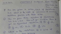
STEP UP 2022, , Chapter 3, CURRENT ELECTRICITY, Electric current (I), Time rate of flow of charge through any section of a conductor is called electric current., Total charge flowing (q), q, q, Electric current (I) = Total time taken (t), =t, ie I = t, , ap, , pu, , ra, , m, , Unit of current in SI is ampere (A), Ohm’s law, Ohm’s law states that physical conditions (temperature, mechanical strain, etc) remaining unchanged, the current flowing through a conductor (I) is, directly proportional to the potential difference (V) across the ends of the, conductor. Mathematically, I α V, or V α I, V=RI, where R is the proportionality constant called electrical resistance., Resistance (R), It is the ability of conductor to oppose electric current. It is the ratio of the, V, potential difference applied to the current flowing through the conductor. R = I, Unit of resistance in SI is ohm (Ω) 1Ω = 1 V/A. Its dimension is [ ML2 T-3 A-2]. Reciprocal of, resistance is known as conductance. Its unit is Ω–1 or mho or siemen (S)., Factors affecting the resistance of a conductor., It is found that the resistance (R) of wire of given material at a constant temperature is, 1) directly proportional to the length ℓ of the conductor,, 2) inversely proportional to the area of cross section (A),, 1, That is , R α ℓ ---------- (1), R α A -------- (2), ℓ, , ℓ, , Vi, , ja, ya, bh, , er, , iM, al, , Combining (1) and (2) we get R α 𝐴, or, R=ρ𝐴, where the proportionality constant ρ is, called specific resistance or resistivity. The resistivity of a conductor depends up on, 1) the nature of the material of the conductor and 2) temperature., Random velocity and Drift velocity., The free electrons of a metallic conductor are in random motion at any temperature greater than, absolute zero (0K). ‘The velocity associated with a free electron in random motion is called random, velocity or thermal velocity.’ On increasing the temperature, random velocity also increases., When an electric field is applied, the free electrons in the conductor are drifted (or accelerated) in a, direction opposite to the direction of the applied electric field. ‘The average velocity acquired by a, free electron in a conductor opposite to the direction of the applied electric field is called drift, velocity., The current (I) flowing through a conductor having area of cross-section A is related with drift, velocity v by an equation I = n e A v where n is the number density of free electrons in the, conductor and e is the electronic charge., Colour code of Carbon resistors, Carbon resistors having a wide range of values of resistance are used in electronic circuits to, control current., Colour, Number, Multiplier Colour Number, Multiplier Tolerance (%), (A & B), (C), (A & B), (C), (D), Black, 0, 100, Blue, 6, 106, Gold ± 5%, 1, 7, Brown, 1, 10, Violet, 7, 10, Silver ± 10%, Red, 2, 102, Grey, 8, 108, No color ± 20%, 3, 9, Orange, 3, 10, White, 9, 10, 4, Yellow, 4, 10, Gold, 10-1, Green, 5, 105, Silver, 10-2, The value of resistances and their percentage accuracy are indicated on, carbon resistors by a color code printed on them. Generally, a carbon, resistor has three colored rings on one side and a colored ring (or no ring), VIJAYABHERI- DISTRICT PANCHAYATH MALAPPURAM, , 22, Dowloaded from www.hssreporter.com, , PLUS TWO PHYSICS
Page 23 :
STEP UP 2022, , on the other side. The color of the rings can be remembered using the following key sentence, “B B ROY of Great Britain has a Very Good Wife wearing Gold Silver Necklace”, The first and second colored rings (A & B) indicate the two significant figures and the third ring, (C) indicates the decimal multiplier. The last ring on the other side (D) indicates the tolerance in, percentage., Joule’s law, The heat energy dissipated in a current flowing conductor is given by H = I2Rt where IV2, , current, R –resistance, t –time. Other forms are H = I2Rt = VIt = R t, The commercial unit of electric energy is kilowatt hour (kWh). 1 kWh = 3.6 x 10⁶ J, Electric power, Electric power is the rate at which electric energy is converted in to other forms of energy., V2, , H, , pu, , ra, , m, , By definition, the electric power P = t = I2 R = V I = R, Unit of power in SI is joule/sec or volt ampere which is called watt. 1 W = 1 J/s = 1 VA, Combination of Resistors - Series and Parallel, The resistance can be connected in two ways: 1) series 2) parallel, Resistance connected in series, Consider three resistances R1, R2 and R3 connected in series across the cell of emf V. In series, circuit same current flows through all resistances whereas different potential differences are, appeared across different resistances., Let I be the current flowing through the circuit. If V1, V2 and V3 are the potential differences across, R1, R2 and R3 respectively,, , Vi, , ja, ya, bh, , er, , iM, al, , ap, , then according to Ohm’s law V1 = I R1 -- (1) V2, = I R2 --- (2) and V3 = I R3 ----(3), The total potential difference applied, V = V1 + V2 + V3 = I R1 + I R2 + I R3, V = I( R1 + R2 + R3) ------- (4), Let Rs be the equivalent resistance, then according to Ohm’s law,, V = I Rs ------ (5), From eq (4) and eq (5) we get, I Rs = I( R1 + R2 + R3) or Rs = R1 + R2 + R3 ---------- (6), If we have n resistances R1 , R2 , R3, --------, Rn connected in series, then effective resistance will be, Rs = R1 + R2 + R3 + ---------- + Rn -------(7), Resistance connected in parallel, Consider three resistances R1, R2 and R3 connected in parallel across the cell of emf V. In parallel, circuit different currents flow through different resistances whereas same potential difference is, appeared across all the resistances., Let I be the current flowing from the cell. If I1, I2 and I3 are the currents flowing through R1, R2, and R3 respectively, then according to Ohm’s law, V, V, V, I1 = R --- (1), I2 = R --- (2), I3 = R ---- (3), 1, , 2, , 3, , The total current flowing from the cell, V, V, V, 1, 1, I = I1 + I2 + I3 = R + R + R = V [R + R +, 1, , 2, , 3, , 1, , 1, , 1, R1, , ]--(4), , Let Rp be the equivalent resistance, then according to, Ohm’s law, I =, , V, Rp, , ------- (5), , From eq(4) eq (5) we get, , V, Rp, , 1, , 1, , = V[R + R +, 1, , 1, , 1, R1, , ] or, , 1, Rp, , =, , 1, R1, , 1, , +R +, 1, , 1, R1, , ------ (6), , If we have n resistances R1 , R2 , R3, --------, Rn connected in parallel, then effective resistance will, 1, 1, 1, 1, 1, be R = R + R + R + -------- + R --------- (7), p, , 1, , 1, , 1, , n, , Internal resistance of a cell, Internal resistance of a cell is the resistance offered by the electrodes and electrolyte of the, cell when a current flows through the cell., Internal resistance of a cell depends on the following factors., VIJAYABHERI- DISTRICT PANCHAYATH MALAPPURAM, , 23, Dowloaded from www.hssreporter.com, , PLUS TWO PHYSICS
Page 24 :
STEP UP 2022, , 1) Distance between the plates 2) Area of the plates immersed in the electrolyte 3) The nature,, concentration and temperature of the electrolyte, Electro motive force (emf) and Terminal potential difference of a cell, Electro motive force (emf) is the potential difference between two terminals of a cell in open, circuit. Terminal potential difference is the potential difference between two terminals of a cell, (or any two points in an electrical circuit) in a closed circuit., Consider a resistance R connected across a cell of emf E whose internal, resistance is r. If a current I is flowing through the circuit, then according to, Ohm’s law,, emf of the cell, E, Current through R, I = total resistance = R+r ------- (1), ER, , Potential difference across R, V = I R = R+r ------ (2), E−V, , E, , Vi, , ja, ya, bh, , er, , iM, al, , ap, , pu, , ra, , m, , Rearranging eq (2) we get r = [ V ]R = [V − 1]R ----- (3), Difference between emf and Potential difference, No emf, P.D, 1, Maximum potential difference between the Difference in potential between two poles of a, two poles of a cell when the cell is in open cell when the cell is in closed circuit., circuit., 2, Independent of the resistance of the circuit Depends on the resistance of the circuit and, and depends on the nature of the electrodes current flowing through the circuit., and nature of the electrolyte., 3, Term emf is used for the source of electric The P.d is measured between any two points of, current., the electric circuit., 4, It is a cause., It is an effect., KIRCHHOFF’S LAWS, 1) First law (Junction rule), The algebraic sum of the currents meeting at a point in an electric circuit is zero. Or at any, junction in an electric circuit, the total incoming current is equal to the total outgoing current., This law obeys the law of conservation of charge., Illustrations, Consider a point O in an electric circuit at which currents I1, I2, I3, I4 and, I5 are flowing through the five conductors in the directions as shown in the, figure. Let us adopt the convention that the current flowing towards the point, O is taken as positive while that flowing away from the point O is taken as, negative. Then I1 and I5 are positive and I2, I3 and I4 are negative. Therefore I1, + (-I2 ) + (-I3) + (- I4 ) + I5 = 0 Or I1 + I5 = I2 +I3 +I4, That is at the junction, the total incoming current is equal to the total outgoing, current, 2) Second law (Loop rule), In any closed part of an electric circuit, the net emf is equal to the algebraic sum of the products of, the resistances and currents flowing through them. This law obeys the law of conservation of, energy., Illustration. Consider the electric circuit consisting of two cells of emfs, E1 and E2 forming a network with resistances R1 , R2 and R3 as shown, in the figure. The distribution of current in different branches is also, shown in figure. Let us adopt the following convention., 1) The current flowing in anticlockwise direction is positive and 2), The emf in the anticlockwise direction is positive., Applying Kirchhoff’s second law to the closed circuit ABCDE1A,, E1 = I1R1 + I3 R3 ------- (1), Similarly for the closed circuit ABCDE2A, E2 = I2R2 + I3 R3 --------- (2), and for the closed circuit A E2DE1A E1 - E2 = I1R1 - I2R2 --------- (3), , VIJAYABHERI- DISTRICT PANCHAYATH MALAPPURAM, , 24, Dowloaded from www.hssreporter.com, , PLUS TWO PHYSICS
Page 25 :
STEP UP 2022, , The Wheatstone’s Bridge, The Wheatstone’s bridge is an arrangement of four resistances and a galvanometer., It is used to measure an unknown resistance using three known resistances., The Wheatstone’s Principle, Four resistances P, Q, R, S, galvanometer G and a cell of emf E are connected as shown in the, figure. If there is no current flowing through the galvanometer, the bridge is said to be balanced., P, R, Then Q = S . This is called Wheatstone’s principle., Derivation of Wheatstone’s principle, Let a current I flow from the cell. On reaching the junction A, I is divided, into two, I1 through P and I - I1 through R. Since current through G is zero,, current through Q is I1 and current through S is I - I1 (Junction rule)., Applying Kirchhoff’s second law to the closed loop ADCA,, -I1 P + (I - I1) R = 0, or, I1 P = (I - I1) R ------ (1), Applying Kirchhoff’s second law to the closed loop BDCB,, -I1 Q + (I - I1) S= 0, or, I1 Q = (I - I1) S ------ (2), I1 P, (I− I1 )R, P, R, eq (1) / eq (2) gives I Q = (I− I ) S, or Q = S ------------ (3), 1, , 1, , ap, , pu, , ra, , m, , eq (3) gives the condition for balance of the bridge and is known as Wheatstone’s principle., Note:, 1) The determination of resistance using Wheatstone’s bridge is a null method. The internal, resistance of the cell and resistance of the galvanometer will not affect the measurement., 2) This method is not suitable for measurement of very low and very high resistance., Metre Bridge, , ja, ya, bh, , er, , iM, al, , Principle, Metre bridge is a modified form of Wheatstone’s bridge., Let an unknown resistance X be connected in the left, gap and resistance box R in the right gap. A cell is, connected between A and B through a key. A sensitive, galvanometer is connected between the central terminal, C and jockey J. This is similar to Wheatstone’s bridge, arrangement. Applying Wheatstone’s principle, if there is no current flowing through the, galvanometer, then, X, resistance of the wire of length AJ, = resistance of the wire of length JB ------- (1), R, , Vi, , If AJ = l cm, JB = (100 – l) cm. Since the wire is uniform, Resistance of the wire of length AJ(l) α, l and the resistance of the wire of length JB (100 - l) α 100 - l, X, 𝑙, Rl, =, or, X, =, ------ (2), R, 100−𝑙, 100−𝑙, Potentiometer: Potentiometer is a device used to, measure emf of a cell. It is also used to measure, internal resistance of a given cell. Potentiometer is, based on no deflection (null deflection) method., When the potentiometer gives zero deflection, it, does not draw any current from the cell., Principle: When a steady current is flowing through, a uniform resistance wire, the potential drop across, any portion of the wire is directly proportional to the length of, that portion. ie: E α l, Application of Potentiometer, (1) Comparison of emf’s of two cells, Let l1 and l2 be the balancing lengths with the cells E1 and E2, respectively, then, E1, 𝑙, E1 α l 1, and, E2 α l2, Therefore E2 = 𝑙1, 2, , VIJAYABHERI- DISTRICT PANCHAYATH MALAPPURAM, , 25, Dowloaded from www.hssreporter.com, , PLUS TWO PHYSICS
Page 26 :
STEP UP 2022, , (2) To determine the internal resistance of a primary cell, (i) Initially in secondary circuit key K' remains open and, balancing length (l1) is obtained. Since cell E is in open circuit,, it’s emf balances on length l1 i.e. E α l1 ……. (1), (ii) Now key K’ is closed so cell E comes in closed circuit. If the, process is repeated again then potential difference V balances on, length l2 i.e. V α l2……. (ii), 𝐸, By using formula internal resistance r = (𝑉 − 1) R, we get, , 𝑙, , r = (𝑙1 − 1) R, 2, , Voltmeter, It draws some current from source of emf, Its sensitivity is low, It is based on deflection method, , •, •, •, , It does not draw any current from the, source of known emf., Its sensitivity is high, It is based on zero deflection method, , Vi, , ja, ya, bh, , er, , iM, al, , ap, , pu, , ra, , m, , •, •, •, , Potentiometer, , VIJAYABHERI- DISTRICT PANCHAYATH MALAPPURAM, , 26, Dowloaded from www.hssreporter.com, , PLUS TWO PHYSICS
Page 27 :
STEP UP 2022, , CHAPTER 4, MOVING CHARGES AND MAGNETISM, Source of magnetic field, A charge at rest produces electric field while a moving charge produces magnetic field in, addition to electric field., Superposition Principle, The magnetic field of several sources is the vector addition of magnetic field of individual, sources., , pu, , ra, , m, , Magnetic Lorentz force, Force on a charge moving in a magnetic field. Fmag = q (v x B) = qvB Sinθ, Where, q –charge, v- velocity, B – magnetic field, θ- angle between v and B., Special Cases:, 1. If the charge is at rest, i.e. v = 0, then F = 0., Thus, a stationary charge in a magnetic field does not experience any force., 2. If θ = 0° or 180° i.e. if the charge moves parallel or anti-parallel to the direction of the magnetic, field, then F = 0., 3. If θ = 90° i.e. if the charge moves perpendicular to the magnetic field, then the force is maximum., Fmax = qvB, , ap, , 4. Force on a negative charge is opposite to that on a positive charge, , iM, al, , Lorentz force, Total force acting on a charge, when it is passing through a crossed electric and magnetic field., FLorentz = q E + q (v x B), , ja, ya, bh, , er, , Right hand thumb rule: Grasp the current carrying conductor in the right hand with the thumb, indicating the direction of current, then the closed fingers will indicate the direction of magnetic, field., Unit of Magnetic field: The SI unit of magnetic field is tesla (T). Its smaller unit is gauss., 1 gauss = 10-4 T. Earth’s magnetic field is about 0.36 gauss or 3.6 x 10⁻⁵ T., Motion in Combined Electrical and Magnetic Fields, , Vi, , ⃗ with velocity v, it, When a charged particle having charge q moves inside a magnetic field 𝐵, ⃗), experiences a force 𝐹 = 𝑞(𝑣 × 𝐵, ⃗ , the force 𝐹 on the charged particle acts as the centripetal force and, When is perpendicular to 𝐵, makes it move along circular path., Let m be the mass of charged particle and r be the radius of the circular path., , v and B are at right angles,, , VIJAYABHERI- DISTRICT PANCHAYATH MALAPPURAM, 27, Dowloaded from www.hssreporter.com, , PLUS TWO PHYSICS
Page 28 :
STEP UP 2022, , Time period of circular motion of the charged particle is, , Angular frequency,, , This is often called cyclotron frequency., , m, , Cyclotron, , Vi, , ja, ya, bh, , er, , iM, al, , ap, , pu, , ra, , It is used to accelerate charged particles or ions to high energy. Electric and magnetic, field are used in combination to increase the energy. The working of a cyclotron is based on the, fact that the frequency of revolution of charged particle is not dependent on the energy., , Particle moves inside the two semi-circular disc-like metal containers D1 and D2 called, dees.When the particle moves from one Dee to another, it is acted upon by electric field.Electric, field changes sign alternately. Therefore, the particle is accelerated by the electric field, which, increases the energy of the particle. The increase in energy increases the radius of the circular, path.Hence, the path is a spiral one., Time period of revolution is, , VIJAYABHERI- DISTRICT PANCHAYATH MALAPPURAM, 28, Dowloaded from www.hssreporter.com, , PLUS TWO PHYSICS
Page 29 :
STEP UP 2022, , This frequency is called the cyclotron frequency., When the frequency of applied voltage is equal to cyclotron frequency, it is called resonance, condition., Since radius of trajectory,, , ra, , m, , Hence, the kinetic energy of ions is ., , pu, , Magnetic force on a current carrying conductor, , F = I (l x B) = IlBSinθ, , iM, al, , Fleming’s Left Hand Rule, , ap, , When a current carrying conductor of length l carrying a current I ampere is kept in a magnetic, field of intensity B, then the force acting on it is given by, , Vi, , ja, ya, bh, , er, , Stretch out the first three fingers of the left hand in mutually perpendicular directions. If, forefinger represents field and central finger represents the current then thumb represents, the direction of force., , VIJAYABHERI- DISTRICT PANCHAYATH MALAPPURAM, 29, Dowloaded from www.hssreporter.com, , PLUS TWO PHYSICS
Page 30 :
STEP UP 2022, , m, , Magnetic Field due to a Current Element, BIOT-SAVART’S LAW, , ra, , , , er, , iM, al, , ap, , pu, , The magnetic field at a point due to the small element of a current carrying conductor is, directly proportional to, 1) the current flowing through the conductor (I), 2) the length of the element (dl), 3) sine of the angle (θ) between r and dl and inversely proportional to, 4) the square of the distance (r) of the point P from dl., Thus the magnetic field due to a current element is, , ja, ya, bh, , Where µ₀ = 4π x 10-7 Tm/A, called permeability of free space., , Vi, , Magnetic Field on the Axis of a Circular Current Loop, , Consider a current loop of radius R carrying I ampere current. P be a point at a distance of x, from its centre O., µ₀ 𝐼𝑑𝑙𝑆𝑖𝑛𝜃, The magnetic field at P due to the current element dl, at A is dB = 4𝜋 𝑟 2, VIJAYABHERI- DISTRICT PANCHAYATH MALAPPURAM, 30, Dowloaded from www.hssreporter.com, , PLUS TWO PHYSICS
Page 34 :
STEP UP 2022, 𝑁, , where n = 2πr , is the number of turns per unit length., Problem: A solenoid of length 0.5 m has a radius of 1 cm and is made up of 500 turns. It carries, a current of 5 A. What is the magnitude of the magnetic field inside the solenoid?, Solution: Given, l = 0.5 m, r = 1 cm = 0.01 m, N = 500, 𝑁, 500, The number of turns per unit length is, n = 𝑙 = 0.5 = 1000 turns/m, The length l = 0.5 m and radius r = 0.01 m. Thus, l/a = 50 i.e., l >> a., Hence, we can use the long solenoid formula, B = μ0n I, = 4 π× 10–7 × 1000 × 5, = 6.28 × 10⁻³ T, , I=5A, , Factors affecting the magnetic field produced by a solenoid or toroid, , ra, , m, , 1. Number of turns per unit length, 2. Medium inside the solenoid or toroid, 3. Current, , ap, , pu, , Torque on Current Loop, Case I - The rectangular loop is placed such that the uniform magnetic field B is in the plane of, loop., , ja, ya, bh, , er, , iM, al, , No force is exerted by the magnetic field on the arms AD and BC., , Vi, , Magnetic field exerts a force F1 on arm AB. ∴ F1 = IbB, Magnetic field exerts a force F2 on arm CD. ∴ F2 = IbB = F1, Net force on the loop is zero., The torque on the loop rotates the loop in anti-clockwise direction., , VIJAYABHERI- DISTRICT PANCHAYATH MALAPPURAM, 34, Dowloaded from www.hssreporter.com, , PLUS TWO PHYSICS
Page 36 :
STEP UP 2022, , Moving Coil Galvanometer, Principle:, , ra, , m, , Its working is based on the fact that when a current carrying coil is placed in a magnetic field, it, experiences a torque., , iM, al, , ap, , pu, , The galvanometer consists of a coil, with many turns free to rotate about a fixed axis in a, uniform radial magnetic field. There is a cylindrical soft iron core which not only makes the field, radial but also increases the strength of the magnetic field. When the current flows through the, coil, a torque acts on it., τ = NIBA, , er, , N is the number of turns, I is the current through the coil, B is the magnetic field and A is the, area of the coil, , ja, ya, bh, , Since the field is radial, θ=90 sinθ =1.The magnetic torque tends to rotate the coil. A spring sp, provides a counter torque kθ that balances the magnetic torque resulting in a steady deflection θ., In equilibrium position of the coil,, , Deflecting torque = Restoring torque, , Vi, , ∴ NIBA = kθ, , Or I =, , k, NBA, , θ =Gθ, , 𝑘, , Where, 𝑁𝐵𝐴 = 𝐺 [constant for a galvanometer called galvanometer constant.], Current sensitivity of the galvanometer is the deflection per unit current., , Voltage sensitivity is the deflection per unit voltage., , VIJAYABHERI- DISTRICT PANCHAYATH MALAPPURAM, 36, Dowloaded from www.hssreporter.com, , PLUS TWO PHYSICS
Page 37 :
STEP UP 2022, , Conversion of a galvanometer to ammeter, , •, , A shunt (low resistance S) is connected in parallel with the galvanometer., , m, , Where,, , A high resistance R is connected in series with the galvanometer., , Where,, , ja, ya, bh, , er, , •, , iM, al, , ap, , pu, , ra, , I → Total current in circuit, G → Resistance of the galvanometer, S →Resistance of the shunt, Ig → Current through galvanometer, Conversion of a galvanometer to voltmeter, , Vi, , V → Potential difference across the terminal A and B, Ig → Current through the galvanometer, R → High resistance, G → Resistance of galvanometer, , VIJAYABHERI- DISTRICT PANCHAYATH MALAPPURAM, 37, Dowloaded from www.hssreporter.com, , PLUS TWO PHYSICS
Page 38 :
STEP UP 2022, , CHAPTER 5, MAGNETISM AND MATTER, Gauss’s Law in magnetism., Gauss’s law states that the surface integral of magnetic field over a closed surface is zero. Or the net, magnetic flux (ϕB) through any closed surface is zero, ϕB = ∲ B ● dS = 0, Earth’s magnetic field., Source of Earth’s Magnetism – Dynamo Effect, Earth’s magnetism is due to the electric currents produced by the motion of metallic fluids such as, molten metallic iron and nickel in the outer core of earth. This is known as Dynamo Effect., , m, , (a) Geographic meridian: The vertical plane passing through the geographic north – south, , ra, , direction is called geographic meridian., , by the freely suspended magnet is called magnetic meridian., , ap, , Magnetic elements of earth:, , pu, , (b) Magnetic meridian: The vertical plane passing through the north – south direction as indicated, , iM, al, , The earth’s magnetic field at a particular place can be specified by three quantities namely, declination, dip or inclination and horizontal intensity. These three quantities are together called, magnetic elements., , er, , 1) Magnetic declination(α), , bh, , Declination at a place is the angle between magnetic meridian and geographical meridian at that, place., , ja, ya, , 2) Dip or inclination (θ), , It is the angle which the earth’s magnetic field B at a particular place makes with the horizontal, , Vi, , line., , 3) Horizontal intensity (BH), It is the horizontal component of earth’s magnetic field at the place., The earth’s magnetic field B can be resolved into two components: BV in the vertical direction and, Bh in horizontal direction, Now from the fig;, Bh = B cosθ and Bv = B sinθ, 𝐵, , tan θ = 𝐵𝑉 or, ℎ, , θ = tan -1, , ( 𝐵𝐵 ), 𝑉, ℎ, , VIJAYABHERI-DISTRICT PANCHAYATH MALAPPURAM, , 38, Dowloaded from www.hssreporter.com, , PLUS TWO PHYSICS
Page 40 :
STEP UP 2022, , 6) Magnetic Flux (𝛟𝑩 ), It is the number of magnetic field lines passing normally through a surface., It’s unit is weber (Wb), , ap, , pu, , ra, , m, , Hysteresis, , er, , iM, al, , The above graph shows the behavior of the material as we take it through one cycle of, magnetisation. An unmagnetised sample is placed inside a solenoid and current through the solenoid, is increased. The magnetic field B in the material rises and saturates as depicted in the curve Oa., Next, H is decreased and reduced to zero. At H = 0, B ≠ 0 (curve ab), The value of B at H = 0 is, called retentivity., , ja, ya, , bh, , Now, the current in the solenoid is reversed and slowly increased. Certain domains are flipped until, the net field inside is reduced to zero. This is represented by the curve bc. The value of H at c is, called coercivity. As the reversed current is increased in magnitude, we once again obtain saturation, (curve cd). Now, the current is reduced (curve de) and reversed (curve ea). The cycle repeats itself., , Vi, , For a given value of H, B is not unique, but depends on previous history of the sample. The, phenomenon of lagging of magnetic induction (B) behind the magnetising field (H) when a, specimen of a magnetic material is subjected to a cycle of magnetisation is called hysteresis., , VIJAYABHERI-DISTRICT PANCHAYATH MALAPPURAM, , 40, Dowloaded from www.hssreporter.com, , PLUS TWO PHYSICS
Page 41 :
STEP UP 2022, , CHAPTER 6, ELECTROMAGNETIC INDUCTION, Magnetic Flux & Faraday's Law of Induction, Faraday’s Experiments, , ra, , m, , Experiment 1 − Current induced by a magnet, , ja, ya, bh, , er, , iM, al, , Experiment 2 − Current induced by a current, , ap, , pu, , The relative motion between the magnet and the coil generates electric current in the coil. The, current so generated is called induced current., , Vi, , When the bar magnet is replaced by a second coil C2 connected to a battery, the steady current in, coil C2 produces a steady magnetic field. As coil C2 is moved towards coil C1, the galvanometer, shows a deflection. This indicates that electric current is induced in coil C1. When C2 is moved, away, the galvanometer shows a deflection again, but this time in the opposite direction. The, deflection lasts as long as coil C2 is in motion., Experiment 3 − Current induced by changing current, , VIJAYABHERI-DISTRICT PANCHAYATH MALAPPURAM, , 41, Dowloaded from www.hssreporter.com, , PLUS TWO PHYSICS
Page 42 :
STEP UP 2022, , The figure shows two coils C1 and C2 held stationary. Coil C1 is connected to galvanometer G while, the second coil C2 is connected to a battery through a tapping key k., It is observed that the galvanometer shows a momentary deflection when the tapping key k is, pressed. If the key is held pressed continuously, there is no deflection in the galvanometer. When, the key is released, a momentary deflection is observed again, but in the opposite direction., Magnetic Flux, The magnetic flux Φ through any surface held in a magnetic field, number of magnetic lines of force crossing the surface., , and, , , which normal to the surface area makes with, , Units of magnetic flux − The SI unit of magnetic flux is Weber (Wb). One Weber is the, amount of magnetic flux over an area of 1 m2 held normal to a uniform magnetic field of, one tesla., 1 Weber = 1 tesla × 1 m2, , er, , •, , iM, al, , ap, , pu, , ra, , m, , Where, θ is the smaller angle between, , is measured by the total, , ja, ya, bh, , The c.g.s unit of Φ is Maxwell (Mx)., 1 Weber = 108 Maxwell, , Faraday’s Law of Electromagnetic Induction, , Vi, , First law − Whenever the amount of magnetic flux linked with a circuit changes, an emf is induced, in the circuit. The induced emf lasts as long as the change in magnetic flux continues., Second law − The magnitude of emf induced in a circuit is directly proportional to the rate of, change of magnetic flux linked with the circuit., According to Faraday’s second law, induced emf, , Where, k is the constant of proportionality, k=1, VIJAYABHERI-DISTRICT PANCHAYATH MALAPPURAM, , 42, Dowloaded from www.hssreporter.com, , PLUS TWO PHYSICS
Page 43 :
STEP UP 2022, , If dΦ is small change in magnetic flux in a small time dt,, , For N turns,, , Lenz Law and Conservation of Energy, , m, , According to Lenz law, the polarity of the induced emf is such that it opposes the change in, magnetic flux responsible for its production., , iM, al, , ap, , pu, , ra, , Experiment:, , ja, ya, bh, , er, , When the bar magnet with its N-pole is moved towards the coil, the induced current produced in, coil S opposes the motion of magnet. It will happen so, if the induced current in the coil S produces, magnetic field lines from left to right i.e., if the induced current flows through the coil S in, clockwise direction (when seen from left)., , Vi, , Lenz Law and Principle of Conservation of Energy, , Lenz law is in accordance with the law of conservation of energy. In the above experiment, when, N-pole of magnet is moved towards the coil, the upper face of the coil acquires North polarity., Thus, work has to be done against the force of repulsion in bringing the magnet closer to the coil., When N pole of magnet is moved away, South pole develops on the upper face of the coil., Therefore, work has to be done against the force of attraction in taking the magnet away from the, coil., This mechanical work in moving the magnet with respect to the coil changes into electrical energy, producing induced current. Hence, energy transformation takes place., , VIJAYABHERI-DISTRICT PANCHAYATH MALAPPURAM, , 43, Dowloaded from www.hssreporter.com, , PLUS TWO PHYSICS
Page 44 :
STEP UP 2022, , Motional Electromotive Force, , Consider that at any time t, the part, the length of the arm of the coil., , of the coil is inside the magnetic field. Let l be, , ra, , m, , Area of the coil inside the magnetic field at time t,, , pu, , ∴Magnetic flux linked with the coil at any time t,, , ap, , Φ = BΔS = Bly, , iM, al, , The rate of change of magnetic flux linked with the coil is given by,, , er, , Where,, , ja, ya, bh, , v → Velocity with the coil pulled out of the magnetic field, , Vi, , If e is the induced emf, then according to Faraday’s law,, , From Fleming’s left hand rule, the current due to induced emf will flow from the end R to Q i.e.,, along SRQP in the coil., Eddy Currents, Eddy currents are the currents induced in a conductor when placed in a changing magnetic field., pplications of Eddy Currents, •, , •, , Electromagnetic damping − Some galvanometers have a fixed core, which is made of nonmagnetic metallic materials. When the coil oscillates, the eddy currents generated in the core, oppose the motion and bring the coil to rest quickly., Induction furnace − In an induction furnace, very high temperature can be produced by, producing large eddy currents., , VIJAYABHERI-DISTRICT PANCHAYATH MALAPPURAM, , 44, Dowloaded from www.hssreporter.com, , PLUS TWO PHYSICS
Page 45 :
STEP UP 2022, , Magnetic braking in trains − Strong electromagnets are situated above the rails in some, electrically powered trains. When the electromagnets are activated, the eddy currents, induced in the rails oppose the motion of the train., •, Inductance, Self-induction − Property of a coil by virtue of which the coil opposes any change in the strength, of current flowing through it by inducing an emf in itself, •, , Self-induction is also called the inertia of electricity., , m, , Coefficient of self-induction:, Suppose I = Current flowing in the coil at any time, , ra, , •, , pu, , Φ = Amount of magnetic flux linked, , iM, al, , ap, , It is found that Φ ∝ I, , Where,, , L is the constant of proportionality and is called coefficient of self induction of the coil, , Vi, , ja, ya, bh, , er, , The emf induced in the coil is given by,, , •, , SI unit of self-inductance is Henry., , •, , 1 Henry =, = 1 Weber/Ampere, Self-Inductance of a Long Solenoid, A long solenoid is one whose length is very large as compared to its radius of cross-section. The, magnetic field B at any point inside such a solenoid is practically constant and is given by,, , VIJAYABHERI-DISTRICT PANCHAYATH MALAPPURAM, , 45, Dowloaded from www.hssreporter.com, , PLUS TWO PHYSICS
Page 46 :
STEP UP 2022, , Where,, μ0 = Absolute magnetic permeability of free space, N = Total number of turns in the solenoid, ∴ Magnetic flux through each turn of the solenoid coil = B × Area of each turn, , Where,, A = Area of each turn of the solenoid, , ra, , m, , Total magnetic flux linked with the solenoid, , pu, , If L is coefficient of self-inductance of the solenoid, then, , ap, , ∴Φ = LI … (iii), , ja, ya, bh, , er, , iM, al, , Equating (ii) and (iii),, , If core is of any other magnetic material, μ0 is replaced by, Mutual Induction, , Vi, , The phenomenon according to which an opposing emf is produced in a coil as a result of change in, current or magnetic flux linked with a neighbouring coil is called mutual induction., , •, , Coefficient of mutual induction − Consider two coils P and S. Suppose that a current I is, flowing through the coil P at any instant i.e.,, Φ∝I, Φ = MI … (i), , VIJAYABHERI-DISTRICT PANCHAYATH MALAPPURAM, , 46, Dowloaded from www.hssreporter.com, , PLUS TWO PHYSICS
Page 48 :
STEP UP 2022, , AC Generator, , m, , Principle − Based on the phenomenon of electromagnetic induction, Construction, , ra, , Main parts of an ac generator:, , Armature − Rectangular coil ABCD, • Filed Magnets − Two pole pieces of a strong electromagnet, • Slip Rings − The ends of coil ABCD are connected to two hollow metallic rings R1 and R2., • Brushes − B1 and B2 are two flexible metal plates or carbon rods. They are fixed and are, kept in tight contact with R1 and R2 respectively., Theory and Working − As the armature coil is rotated in the magnetic field, angle θ between the, field and normal to the coil changes continuously. Therefore, magnetic flux linked with the coil, changes. An emf is induced in the coil. According to Fleming’s right hand rule, current induced in, AB is from A to B and it is from C to D in CD. In the external circuit, current flows from B2 to B1., , ja, ya, bh, , er, , iM, al, , ap, , pu, , •, , To calculate the magnitude of emf induced:, Suppose, A → Area of each turn of the coil, N → Number of turns in the coil, , Vi, , → Strength of magnetic field, , θ → Angle which normal to the coil makes with at any instant t, ∴ Magnetic flux linked with the coil in this position:, = NBA cos θ= NBA cos ωt …(i), Where, ‘ω’ is angular velocity of the coil, As the coil rotates, angle θchanges. Therefore, magnetic flux Φ linked with the coil changes and, hence, an emf is induced in the coil. At this instant t, if e is the emf induced in the coil, then, , ∴e = NAB ω sin ωt, , VIJAYABHERI-DISTRICT PANCHAYATH MALAPPURAM, , 48, Dowloaded from www.hssreporter.com, , PLUS TWO PHYSICS
Page 49 :
STEP UP 2022, , CHAPTER 7, ALTERNATING CURRENT, AC Voltage Applied to a Resistor, Inductor, and Capacitor, AC Voltage Applied to a Resistor, , pu, , ra, , m, , (ac voltage), , In pure resistor, voltage and current are in phase with each other., , •, , Instantaneous power dissipated in the resistor is, , •, , Average power,, , •, , Root mean square current,, , Vi, , ja, ya, bh, , er, , iM, al, , ap, , •, , VIJAYABHERI- DISTRICT PANCHAYATH MALAPPURAM, , 49, Dowloaded from www.hssreporter.com, , PLUS TWO PHYSICS
Page 56 :
STEP UP 2022, , ∴, =1, Therefore, maximum power is dissipated., Case II, For pure inductive circuit or pure capacitive circuit, the phase difference between current and, voltage is, , ., , Therefore, zero power is dissipated. This current is sometimes referred to as watt-less current., Case III, For LCR series circuit,, , When a capacitor is connected with an inductor, the charge on the capacitor and current in the, circuit exhibit the phenomenon of electrical oscillations., , ja, ya, bh, , er, , iM, al, , •, , ap, , Therefore, maximum power is dissipated., LC Oscillations, , pu, , ra, , m, , Therefore, power is dissipated only in the resistor., Case IV, For power dissipated at resonance in an LCR circuit,, , •, , Vi, , Let at t = 0, the capacitor is charged qm and connected to an inductor., • Charge in the capacitor starts decreasing giving rise to current in the circuit., • Let, q → Charge, t→ Time, i→ Current, According to Kirchhoff’s loop rule,, , This equation is of the form of a simple harmonic oscillator equation., , VIJAYABHERI- DISTRICT PANCHAYATH MALAPPURAM, , 56, Dowloaded from www.hssreporter.com, , PLUS TWO PHYSICS
Page 57 :
STEP UP 2022, •, , 1, , The charge oscillates with a natural frequency of 𝜔0, and it varies sinusoidally with, √𝐿𝐶, time as, , Where,, → Maximum value of q, Φ → Phase constant, •, , At, t=0, q=, , ,, , we have cos Φ= 1 or Φ= 0, , ra, , m, , ∴ q = qm cos (ω0t ), , pu, , ∴ i = im sin ω0 tWhere, im = ω0 qm, •, , ap, , LC oscillations are similar to the mechanical oscillation of a block attached to a spring., Transformers, , ja, ya, bh, , er, , iM, al, , Principle − It works on the principle of electromagnetic induction. When current in one circuit, changes, an induced current is set up in the neighbouring circuit., Construction, , Vi, , Step-up transformer, , Step-down transformer, Working, •, , Alternating emf is supplied to the primary coil PP’. The resulting current produces an, induced current in secondary., , VIJAYABHERI- DISTRICT PANCHAYATH MALAPPURAM, , 57, Dowloaded from www.hssreporter.com, , PLUS TWO PHYSICS
Page 58 :
STEP UP 2022, •, •, , Magnetic flux linked with primary is also linked with the secondary. The induced emf in, each turn of the secondary is equal to that induced in each turn of the primary., Let, EP − Alternating emf applied to primary, nP − Number of turns in the primary, − Rate of change of flux through each turn of primary coil, , Es− Alternating emf of secondary, , m, , ns − Number of turns in secondary, , ap, , pu, , ra, , Dividing equation (2) by (1),, , For step-up transformer, K > 1, ∴ Es > Ep, , •, , For step-down transformer, K < 1, ∴ Es < Ep, , •, , According to law of conservation of energy,, Input electrical power = Output electrical power, , er, , Transformers are used in telegraph, telephone, power stations, etc., Losses in transformer:, , Vi, , •, , ja, ya, bh, , EpIp = EsIs, , •, , iM, al, , •, , o, o, o, o, , Copper loss − Heat in copper wire is generated by working of a transformer. It can, be diminished using thick copper wires., Iron loss − Loss is in the bulk of iron core due to the induced eddy currents. It is, minimized by using thin laminated core., Hysteresis loss − Alternately magnetizing and demagnetizing, the iron core cause, loss of energy. It is minimized using a special alloy of iron core with silicon., Magnetic loss − It is due to the leakage of magnetic flux., , VIJAYABHERI- DISTRICT PANCHAYATH MALAPPURAM, , 58, Dowloaded from www.hssreporter.com, , PLUS TWO PHYSICS
Page 60 :
STEP UP 2022, , Electromagnetic Waves, The periodic change in electric and magnetic fields that can propagate through air or vacuum with, the velocity of light., , iM, al, , ap, , pu, , ra, , m, , The fields are represented as, , er, , The direction of electromagnetic wave is mutually perpendicular to both E and B., , Vi, , ja, ya, , bh, , Properties of EM waves, ▪ They are self-sustaining oscillations of electric and magnetic fields in free space, or vacuum., ▪ Shows transverse wave nature., ▪ No material medium is needed for its propagation., ▪ EM waves are not deflected in electric field and magnetic field., ▪ The velocity of em waves in any media is given by, , ▪, ▪, , EM waves are polarized., Electromagnetic waves carry energy and momentum like other waves., , Electromagnetic Spectrum, The arrangement of electromagnetic waves according to their wavelength or frequency., In the increasing order of wavelength, they may be arranged as Gamma rays, X rays, UV rays,, Visible rays, IR waves, Micro waves and Radio waves., Frequency range and Wavelength range of EM Waves, VIJAYABHERI-DISTRICT PANCHAYATH MALAPPURAM, , 60, Dowloaded from www.hssreporter.com, , PLUS TWO PHYSICS
Page 63 :
STEP UP 2022, , CHAPTER 9, RAY OPTICS AND OPTICAL INSTRUMENTS, , pu, , ra, , m, , Reflection of light: When a ray of light, after incident on a boundary, is coming back into the same, media, then this phenomenon is called reflection of light., A convex or concave mirror can be assumed to be a part of spherical surface., A concave mirror converges light rays and a convex mirror diverges light rays., (i) Pole (P): Midpoint of the, mirror, (ii) Centre of curvature (C): Centre, of the sphere of which the mirror, is a part., (iii) Radius of curvature (R):, Distance between pole and centre, of curvature., (Rconcave = –ve , Rconvex = +ve , Rplane = α), (iv) Principle axis: A line passing through P and C., (v) Focus (F): An image point on principle axis for which object is at infinity., (vi) Focal length (f): Distance between P and F., Relation between f and R: f = 2R Note: ( f concave = –ve , f convex = + ve , f plane = α ), 1, (viii) Power: The converging or diverging ability of mirror. 𝑃 = 𝑓, , ap, , (ix) Aperture: Effective diameter of light reflecting area., (x) Focal plane: A plane passing from focus and perpendicular to principle axis., , iM, al, , Relation between focal length and radius of curvature, , ja, ya, bh, , er, , From the diagram, , For small θ, tan θ ≈ θ, and, , tan 2θ ≈ 2θ., , Thus,, , Vi, , For small θ, the point D is very close to the point P. Therefore, FD = f and CD = R., , Mirror equation and magnification:, The relation connecting the object distance (u), image, distance (v) and the focal length (f) is called mirror, equation., The two right-angled triangles A′B′F and MPF are similar., , VIJAYABHERI- DISTRICT PANCHAYATH MALAPPURAM, , 63, Dowloaded from www.hssreporter.com, , PLUS TWO PHYSICS
Page 64 :
STEP UP 2022, , Therefore,, (Since ∠ APB = ∠ A′PB′, the right-angled, triangles A′B′P and ABP are also similar.), That is, , Comparing the equations,, , , But, , Thus we get, , ra, , m, , Therefore, , pu, , This equation is known as mirror equation., Here, u = Distance of object from pole, v = distance of image from pole and f = Focal length, , −𝑣, 𝑢, , iM, al, , Also, m =, , ap, , Magnification (or linear magnification) is defined as the ratio of size of the image to the size of the, object., IMAGE FORMATION OF A CONCAVE MIRROR, 𝑖𝑚𝑎𝑔𝑒, 𝐼, Magnification = 𝑜𝑏𝑗𝑒𝑐𝑡 or m = 𝑂 ., , of, , er, , Similarly, areal magnification is defined as the ratio, area of the image to the area of the object., , Vi, , ja, ya, bh, , A convex mirror always forms a virtual and, diminished image irrespective of the position of the, object., Uses of mirrors, (i) Concave mirror: Used as a shaving mirror, in search light, in cinema projector, in telescope, by, E.N.T. specialists etc., (ii) Convex mirror: In road lamps, side mirror in vehicles etc., Refraction of light: The bending of the ray of light passing from one medium to the other medium, is called refraction. Refractive index of a medium is that characteristic which decides speed of light, in it. It is a scalar, unitless and dimensionless quantity. The medium with a higher refractive index is, called denser medium and a medium with lower refractive index is called rarer medium., , Laws of Refraction:, First law: The incident ray, the refracted ray and the normal to the interface at the point of, incidence, all lie in the same plane., Second law or Snell’s law: The ratio of sine of the angle of incidence to the sine of the angle of, refraction (r) is a constant., VIJAYABHERI- DISTRICT PANCHAYATH MALAPPURAM, , 64, Dowloaded from www.hssreporter.com, , PLUS TWO PHYSICS
Page 65 :
STEP UP 2022, 𝑠𝑖𝑛𝑖, , 𝑛, , That is 𝑠𝑖𝑛𝑟 = 𝑛2 (n2 - refractive index of second medium, n1 - refractive index of first medium), 1, , Dependence of Refractive index, (i) Nature of the media of incidence and refraction., (ii) Colour of light or wavelength of light., (iii) Temperature of the media: Refractive index decreases with the increase in temperature., Applications of refraction:, 1.Apparent depth: If object and observer are situated in, different medium then due to refraction, object appears, to be, displaced from its real position. If an object in a denser, medium is viewed from a rarer medium the image, appears to be raised towards the surface., 𝑅𝑒𝑎𝑙𝐷𝑒𝑝𝑡ℎ, Refractive index of the medium, n = 𝐴𝑝𝑝𝑎𝑟𝑒𝑛𝑡𝐷𝑒𝑝𝑡ℎ, , pu, , ra, , of, , ap, , Thus, we see the sun at an apparent position raised above the, horizon. This is the reason for early sunrise and delayed, sunset., , sun, , m, , 2. Apparent position of sun: A ray of light travelling from, to earth is travelling from rarer to denser medium. So, it, bends towards the observer and he see the shifted position, the sun., , iM, al, , Total Internal Reflection, , Total internal reflection is the phenomenon of, reflection of light into a denser medium from an, interface of the denser medium and the rarer medium., , •, , Two essential conditions for total internal reflection:, , ja, ya, bh, , er, , •, , o Light should travel from denser medium to rarer, medium., o Angle of incidence (i) should be greater than the critical angle for the pair of media, in contact., , Vi, , Relation between refractive index (n) and critical angle (C), Critical angle is the angle of incidence in the denser medium for which the angle of, refraction in the rarer medium is 90o., When, i = C, r = 90°, Applying Snell’s law,, n2 sin C = n1 sin 90° = n1 × 1 (n1 is the refractive index of the rarer medium and, n2 is the refractive index of the denser medium), , VIJAYABHERI- DISTRICT PANCHAYATH MALAPPURAM, , 65, Dowloaded from www.hssreporter.com, , PLUS TWO PHYSICS
Page 66 :
STEP UP 2022, , Some applications of total internal reflection, 1) Brilliance of diamond − The critical angle for diamond-air interface is 24.4°. The diamond, is cut suitably so that light entering the diamond from any face falls at an angle greater than, 24.4°, suffers multiple total internal reflections at the various faces, and remains within the, diamond. Hence, the diamond sparkles., , ja, ya, bh, , 4) Optical fibres, , er, , 3) Prism − Prism is designed to, bend light by 90° or 180° and to, make use of total internal, reflection., , iM, al, , ap, , pu, , ra, , m, , 2) Mirage → It is an optical illusion in, which an object such as tree appears to be, inverted., This happens due to uneven heating of the, different layers of air due to which density, and refractive index of air goes on, increasing slightly with height above the, surface of earth., As a result of this, light from a tall object, such as a tree, passes through a medium whose, refractive index decreases towards the ground. Thus, a ray of light undergoes total internal, reflection. To a distant observer, the light appears to be coming from somewhere below the, ground., , Vi, , Optical fibres are extensively used for transmitting, audio and video signals through long distances., These make use of the phenomenon of total, internal reflection. When a signal in the form of, light is directed at one end of the fibre at a suitable, angle, it undergoes repeated total internal reflections along the length of the fibre and finally, comes out from the other end., Refraction at spherical surfaces, If n1 is the refractive index of first medium and n2 the refractive index of second medium, then, From triangle OMP,, , From triangle PCM,, , From triangle PMI,, , VIJAYABHERI- DISTRICT PANCHAYATH MALAPPURAM, , 66, Dowloaded from www.hssreporter.com, , PLUS TWO PHYSICS
Page 67 :
STEP UP 2022, , From triangle OMC, Exterior angle = sum of interior angles. Thus,, From triangle IMC, By Snell’s law, If і and r are small,, , or, , Substituting for і and r, , or, , But PO = -u , PI = v , PC =R, , ra, , m, , Therefore, Thus equation (3) becomes, , ap, , pu, , This is the equation of refraction at, convex surface., , er, , iM, al, , Refraction by a lens: Lens is a transparent medium bounded by two refracting surfaces, such that, at least one surface is spherical., , ja, ya, bh, , Lens, , Vi, , maker’s formula, For the curved surface ABC,, , For the curved surface ADC,, , where R2 is the radius of curvature of ADC, Now, adding equation 1 and 3, we get, , VIJAYABHERI- DISTRICT PANCHAYATH MALAPPURAM, , 67, Dowloaded from www.hssreporter.com, , PLUS TWO PHYSICS
Page 68 :
STEP UP 2022, , Dividing the above equation by n1,, , If the object is at infinity, the image is formed at the principal, focus. Thus, if u=infinity and v = f, equation 4 becomes, Thus, the lens maker’s formula is given by, , m, , Now, comparing equations 4 and 5, we may write,, , ap, , pu, , ra, , This is known as thin lens formula.The formula is valid for both convex as well as concave, lenses and for both real and virtual images., Linear magnification (m), 𝐼, 𝑣, It is defined as the ratio of the size of the image to that of the object. m = 𝑂 = 𝑢, The value of m is negative for real images and positive for virtual images., Power of a lens (P), , iM, al, , Power of a lens is the reciprocal of focal length measured in metre., Power of a lens is a measure of the convergence or divergence when, light falls on it. The SI unit for power of a lens is diopter (D). Power of, lens is positive for a converging lens and negative for a diverging lens., , a, , ja, ya, bh, , er, , If several thin lenses of focal length f1, f2, f3,... are in, contact, the effective focal length of their combination f, is, given by, Thus, the power P is given by, , Vi, , The total magnification m is, , Refraction through a Prism: Prism is a transparent, medium bounded by refracting surfaces, such that the, incident surface and emergent surface are plane and, parallel., , non-, , In the quadrilateral AQNR, two of the angles (at the, vertices Q and R) are right angles, therefore, the sum of, the other angles of the quadrilateral AQNR is 1800., ∠A + ∠QNR = 180o, From the triangle QNR, , Comparing these two equations, VIJAYABHERI- DISTRICT PANCHAYATH MALAPPURAM, , 68, Dowloaded from www.hssreporter.com, , PLUS TWO PHYSICS
Page 69 :
STEP UP 2022, , We know, exterior angle = sum of interior angles, thus d = (i - r1) + (e - r2), d = (i + e – (r1+r2) ) or d = (i + e - A), At the minimum deviation, d = D, і = e, r1 = r2 = r therefore, and, , Thus, Snell’s law becomes,, Refractive index,, , m, , i-d curve of a prism, , iM, al, , ap, , pu, , ra, , Dispersion by Prism: The phenomenon of splitting of light into its component colors is, known as dispersion. The pattern of color components of light is called the spectrum of, light. Dispersion takes place because the refractive index of medium for different, wavelengths (colors) is different. When white light is passed through a prism, it splits into, its seven component colors (VIBGYOR)., The medium in which the different colors of light travel with different velocities is, called a dispersive medium. Eg: Glass. The medium in which all colors travel with the, same speed is called non- dispersive medium. Eg:- vacuum, , Microscope, , er, , Simple Microscope, , ja, ya, bh, , When image is formed at the near point, , Vi, , The angular magnification of a simple microscope is the ratio of, the angle β subtended at the eye by the image at the near point, and the angle α subtended at the unaided eye by the object at the, near point., , Now,, , and, , Since the angles are small,, , This gives the linear magnification produced by the lens., VIJAYABHERI- DISTRICT PANCHAYATH MALAPPURAM, , 69, Dowloaded from www.hssreporter.com, , PLUS TWO PHYSICS
Page 70 :
STEP UP 2022, , It can be proved that, , We know that,, , ra, , m, , v=−D, , and, , iM, al, , ap, , In this case,, , pu, , When the image is formed at infinity, , er, , Compound Microscope, , ja, ya, bh, , A compound microscope consists of two convex lenses, co-axially separated by some distance. The lens nearer to, the object is called the objective. The lens through which, the final image is viewed is called the eyepiece., Angular Magnification or Magnifying Power of the, Compound Microscope, , Vi, , Angular magnification or magnifying power of a compound microscope is defined as the ratio of, the angle β subtended by the final image at the eye to the angle α subtended by the object seen, directly, when both are placed at the least distance of distinct vision., ∴Angular magnification,, Since the angles are small,, α ≈ tan α, , &, , β ≈ tan β, , VIJAYABHERI- DISTRICT PANCHAYATH MALAPPURAM, , 70, Dowloaded from www.hssreporter.com, , PLUS TWO PHYSICS
Page 71 :
STEP UP 2022, , Thus, the magnification produced by the compound microscope is the product of the magnifications, produced by the eyepiece and objective., , Where, Me and M0 are the magnifying powers of the eyepiece and objective respectively, The linear magnification of the real inverted image produced by the eyepiece is., , m, , Linear magnification,, , ra, , → Focal length of the eye piece, , Where,, , ap, , pu, , is the linear magnification of the object produced by the objective., , er, , iM, al, , From (i), (ii), and (iii),, , ja, ya, bh, , Magnifying power, when final image is at infinity:, , If u0 is the distance of the object from the objective and v0 is the distance of the image from the, objective, then the magnifying power of the objective is, 𝑉, 𝑀0 𝑢0, 0, , 𝑒, , Vi, , When the final image is at infinity,, 𝐷, 𝑀𝑒 = 𝑓, , Magnifying power of compound microscope,, , If the object is very close to the principal focus of the objective and the image formed by the, objective is very close to the eyepiece, then, , Where, L = Length of the microscope, In this case, the microscope is said to be in normal adjustment., , VIJAYABHERI- DISTRICT PANCHAYATH MALAPPURAM, , 71, Dowloaded from www.hssreporter.com, , PLUS TWO PHYSICS
Page 72 :
STEP UP 2022, , CHAPTER 10, WAVE OPTICS, Wave Theory of light:, In 1678, a Dutch Physicist and astronomer, Christian Huygens put forward the wave theory, of light. According to this theory, light is propagated in the form of waves through an all-pervading, hypothetical medium called ether. These waves carry energy and produce the sensation of vision on, falling on the eye. The phenomenon like interference, diffraction and polarisation are well explained, using this concept., Wave front:, , iM, al, , ap, , pu, , ra, , m, , According to Huygenes theory, light travels in the form of waves. During the wave, propagation, all particles of the medium which are located at the same distance from the source, receive the disturbance simultaneously and vibrate in the same phase., , er, , The wavefront is defined as the locus of all points which have the same phase of vibration., , Vi, , ja, ya, bh, , The common types of wave fronts are:, , (i) Spherical wavefront: The wavefront near a point source is a spherical wavefront. This is, because at a particular instant all the disturbances from a point source of light reach on the surface, of a sphere and will be in the same phase of vibration., (ii) Cylindrical wavefront: If a source of light is linear in shape (eg: slit) and is very near, the, wavefront is cylindrical. This is because, all the points equidistant from a linear source lie on the, surface of a cylinder., (iii) Plane wavefront: If the source of light is at infinity, we will get plane wavefront., , VIJAYABHERI- DISTRICT PANCHAYATH MALAPPURAM, , 72, Dowloaded from www.hssreporter.com, , PLUS TWO PHYSICS
Page 73 :
STEP UP 2022, , Any line perpendicular to a wavefront is called ray of light., Huygen’s Principle:, Huygen’s Principle states that:, (1) Every point on a given wavefront can be considered as a source of secondary waves, called, wavelets., , m, , (2) The secondary wavelets spread in all directions with the velocity of light., , ra, , (3) The new wavefront at any instant is the envelop of these wavelets in the forward direction., , pu, , Reflection of a plane wavefront at a plane surface:, , iM, al, , ap, , Let XY be a plane reflecting surface and AB be the incident plane wavefront. All the, particles on AB will be vibrating in phase. Let i be the angle of incidence. By the time the, disturbance at A reaches C, the secondary waves from the point B will travel a distance BD = AC., With the point B as centre and AC as radius, construct a sphere., , Vi, , ja, ya, bh, , er, , Draw tangent CD to the sphere. Then CD is the reflected wavefront., , In the triangles BAC and BDC, BC is common. BD = AC and, ∠BAC = ∠BDC = 900, Therefore, the triangles are congruent., ∠ABC =∠BCD, i.e,, i = r., Thus, The angle of incidence is equal to the angle of reflection., Also, the incident ray, reflected ray and the normal to the surface at the point of incidence, all lie in the same plane., These are the laws of reflection., , VIJAYABHERI- DISTRICT PANCHAYATH MALAPPURAM, , 73, Dowloaded from www.hssreporter.com, , PLUS TWO PHYSICS
Page 75 :
STEP UP 2022, 𝑐, , Or c1 = n, ∴, , sin 𝑖, sin 𝑟, , sin 𝑖, sin 𝑟, , =, , =, n2, n1, , 1, , c1, c2, , 𝑐, , and c2 = n, c/n, , 2, , 𝑐, , = c/n1 = n x, 2, , =n, , 1, , n2, 𝑐, , n, , = n2, 1, , (This is Snell’s law in refraction), , Now the incident ray, refracted ray and the normal are in the same plane., Thus, both laws of refraction are proved., , Interference, Interference is the phenomenon in which two waves superpose to form the resultant wave, of the lower, higher or same amplitude., , m, , The following are the types of light interference:, • Constructive interference, • Destructive interference, , Vi, , ja, ya, bh, , er, , Young’s Double Slit Experiment, , iM, al, , ap, , pu, , ra, , To observe the effects of certain optical phenomena like interference in a lab, you will need, coherent sources of light, Coherent Sources, If the sources have zero or constant phase difference and the same frequency, then the two sources, are considered to be coherent. Most of the light sources around us like the bulb, sun, candle, etc., are a combination of a multitude of incoherent sources of light. For coherent sources, the laser is, an example, , VIJAYABHERI- DISTRICT PANCHAYATH MALAPPURAM, , 75, Dowloaded from www.hssreporter.com, , PLUS TWO PHYSICS
Page 76 :
STEP UP 2022, , Condition for bright (Constructive interference), Path difference = nλ (Where n= 0,1,2,3…….), Condition for Dark (Destructive interference), 𝜆, Path difference = (2n+1)2 (Where n= 0,1,2,3…….), Band Width or Fringe with of Interference pattern, 𝐷𝜆, 𝛃=𝑑, , Diffraction, Diffraction of light is defined as the bending of light around corners such that it spreads out and, illuminates areas where a shadow is expected, To observe diffraction the size of the obstacle must be comparable with wave length of light, , er, , iM, al, , ap, , pu, , ra, , m, , Diffraction due to Single Slit, , 𝜃=, , 𝑛𝜆, , ja, ya, bh, , Condition for Minimum Intensity(dark), , (n = 1,2,3…….) a→ Length of slit, , 𝑎, , Condition for Maximum other than Principal Maximum, (2𝑛+1)𝜆, 2𝑎, , (n = 1,2,3…….) a→ Length of slit, , Vi, , 𝜃=, , Difference between interference and diffraction, Interference, Diffraction, 1 It is due to the superposition of It is due to the superposition of, secondary wavelets from two secondary wavelets emitted from, different wavefront produced by various points of the same wavefront, two coherent sources, 2, 3, , Fringes are equally spaced, Bright fringes are of same, intensity, , 4, , Comparing with diffraction, it, has large number of fringes, , Fringes are unequally spaced, Bright fringes are of different, intensity (Max Intensity at the center, fringe and intensity decrease sharply, for 1st ,2nd…etc bright fringes), It has less number of fringes, , VIJAYABHERI- DISTRICT PANCHAYATH MALAPPURAM, , 76, Dowloaded from www.hssreporter.com, , PLUS TWO PHYSICS
Page 77 :
STEP UP 2022, , Polarisation, According to electromagnetic theory, light is the propagation of mutually perpendicular, vibrating electric and magnetic fields., The electric field functions as light vector. When light is passed through certain crystals like, tourmaline, the vibrations of electric field vector are restricted. This property exhibited by light is, known as polarisation., Light having electric field vector vibrations confined to a single plane and in a particular, direction is known as linearly polarised or plane polarised light., Polarisation is exhibited by transverse waves only. Thus, polarisation proves the light is, transverse in nature., , iM, al, , ap, , pu, , ra, , m, , Demonstration, , Vi, , ja, ya, bh, , er, , Polarisation can be demonstrated using a tourmaline crystal. Light from a source is allowed, to pass through a tourmaline crystal. The vibrations parallel to the optical axis will pass through it, and other vibrations are absorbed by the crystal., The crystal is called polarisor or polaroid, since the emergent light is polarised. To test, whether the emergent light is polarised or not, a second tourmaline crystal is used., Keeping the first crystal fixed, the second one is rotated about the incident ray as axis. Then, it is found that the intensity of emergent light from second crystal varies between maximum and, minimum (zero)., The intensity of transmitted light is maximum when the polarising directions are parallel, and intensity falls to zero when the polarising directions become perpendicular to each other., The light coming out of first polaroid has acquired a property which the incident light did, not have (i.e. the intensity is reduced to half). This property is called polarisation of light., The second crystal is called analyser or detector., The plane in which the vibrations of electric field vector are confined is, known as plane of vibration and the plane perpendicular to the plane of vibration is known as, plane of polarisation., Malus’s law:, Malus’s law states that when a beam of plane polarised light of intensity I0 is incident on the, analyser, then the intensity I of the emergent light is directly proportional to square of the cosine of, the angle (θ) between the polariser and analyser., Intensity of light coming out of the analyser is, I = I0cos2θ, , VIJAYABHERI- DISTRICT PANCHAYATH MALAPPURAM, , 77, Dowloaded from www.hssreporter.com, , PLUS TWO PHYSICS
Page 78 :
STEP UP 2022, , Polarisation by reflection, , Malus in 1808 found that when light gets reflected from a transparent medium, the reflected, light is partially polarised. At a particular angle of incidence, the reflected light is fully polarised., , ra, , m, , This particular angle is known as polarising angle or angle of polarisation or Brewster, angle (⍬) for that medium., , ap, , pu, , When light is incident at polarising angle, the reflected and refracted rays are mutually, perpendicular., i.e. r + ⍬ = 900; r = angle of refraction and ⍬= polarising angle., , iM, al, , Brewster’s law, Brewster’s law states that “the tangent of the polarising angle is equal to the refractive, index of the medium on which light is incident”, , Vi, , ja, ya, bh, , er, , If ⍬is the polarising angle and n is the refractive index of the medium, then tan⍬ = n. This, is Brewster’s law, , Proof :, By Snell’s law of refraction,, sin 𝑖, 𝑠𝑖𝑛 𝑟, , n, , = n2 = n, 1, , where n is the refractive index of the refracting medium., From the figure ., i =⍬, Also r + ⍬ = 90, r = 90 −⍬, VIJAYABHERI- DISTRICT PANCHAYATH MALAPPURAM, , 78, Dowloaded from www.hssreporter.com, , PLUS TWO PHYSICS
Page 79 :
STEP UP 2022, sin ⍬, 𝑠𝑖𝑛 (90 −⍬), , = n, , But sin (90−⍬) = cos⍬, sin ⍬, ∴ cos ⍬ = n, tan ⍬ = n, This is Brewster’s law, Uses of plane polarised light, (i) To project stereoscopic pictures on a screen., (ii) If polarised light is used in optical instruments, it becomes polarised instrument., (iii) It is used in liquid crystal display (LCD)., (iv) Sun glasses., , ra, , m, , Polaroid, Polaroid is a polariser in the form of a large film (sheet). When unpolarised light is passes, through a polaroid, we get polarised light., , Vi, , ja, ya, bh, , er, , iM, al, , ap, , pu, , Uses: (i) In polarising optical instruments., (ii) In order to improve colour contrast in old oil paintings, polaroids are used., (iii) Used to produce and view 3D films., (iv) In aeroplanes, polaroid glasses are used to control light coming in., (v) In sun glasses, (vi) In wind glass of vehicles to avoid glare., , VIJAYABHERI- DISTRICT PANCHAYATH MALAPPURAM, , 79, Dowloaded from www.hssreporter.com, , PLUS TWO PHYSICS
Page 80 :
STEP UP 2022, , CHAPTER 11, DUAL NATURE OF RADIATION & MATTER, , Work function (Φ0), Work function is the minimum external energy required to eject an electron from a metal., , Φ0 = hν0 = hc / λ0, Photoelectric effect, Emission of electrons from a metal surface when an electromagnetic radiation with suitable, frequency is incident on it is called photo electric effect., Planck’s quantum theory, According to quantum theory the radiation has particle nature; it is made up of large, , m, , number of small packets of energy called light quanta or photons., , ra, , Properties of photons, , pu, , 1. Travels in straight line with the speed of light., , 2. Photons are electrically neutral so they are not deflected by electric or magnetic field., , iM, al, , 4. Energy of each photon is given by E = hν, , ap, , 3. Rest mass of photon is zero; they possess mass by its motion., , h− Planck’s constant h = 6.63 × 10 -34 Js, , er, , ν− Frequency of light, , ja, ya, bh, , Einstein’s Photoelectric Equation, •, , Einstein explained photoelectric emission with the help of Planck’s quantum theory., , •, , According Einstein’s photoelectric equation, the energy of the falling photon (hν) may, be used for two purposes., , Vi, , 1. Work to liberate the electron from the metal surface (Work function Φ0), 2. To give maximum kinetic energy Kmax to the emitted photoelectrons., According to Einstein’s photoelectric equation, , hν = Φ0 + Kmax, Kmax = hν - Φ0, Kmax = h(ν-ν0), , ν0is threshold frequency. It is the minimum energy required to eject an electron, from a metal surface., Saturation Current, The maximum value of the photo electric current is called Saturation Current., VIJAYABHERI-DISTRICT PANCHAYATH-MALAPPURAM, , 80, Dowloaded from www.hssreporter.com, , PLUS TWO PHYSICS
Page 81 :
STEP UP 2022, , Stopping Potential, The minimum negative (retarding) potential ν0 for which photo current stops or become zero, is called the cut-off or stopping potential, Laws of Photoelectric effect, , •, , The photoelectric current is directly proportional to the intensity of incident light and, , For a given frequency of the incident radiation, the stopping potential is independent of its, , pu, , •, , ra, , m, , independent of the frequency., , ja, ya, bh, , er, , iM, al, , ap, , intensity., , ❖ Greater the frequency of incident light, greater is the maximum kinetic energy of photo, , Vi, , electrones, , •, , For each metal there is a threshold frequency below which no photoelectron emission is, possible, , VIJAYABHERI-DISTRICT PANCHAYATH-MALAPPURAM, , 81, Dowloaded from www.hssreporter.com, , PLUS TWO PHYSICS
Page 87 :
STEP UP 2022, , 1, 1, 1, = 𝑅 ( 2 − 2), 𝜆𝑖𝑓, 𝑛𝑓 𝑛𝑖, Here 𝑅 =, , 𝑚𝑒 4, 8𝜀𝑜2 ℎ3 𝑐, , is called Rydberg constant., , Its value is 1.097 × 10⁷ 𝑚−1 ., 1, , 𝑠𝑖𝑛𝑐𝑒 𝜆 = 𝑣̅ , 𝑡ℎ𝑒 𝑤𝑎𝑣𝑒 𝑛𝑢𝑚𝑏𝑒𝑟, 𝑣̅𝑖𝑓 = 𝑅 (, , 1, 1, − 2), 2, 𝑛𝑓 𝑛𝑖, , Spectral series of hydrogen atom, , m, , The hydrogen spectrum consists of a number of series and each series consists of a number of, , ra, , lines. A series is due to the transition to a particular energy state from higher energy states. The, , pu, , important series are given below,, , ap, , 1. Lyman series, , iM, al, , This series is in the ultraviolet region and is due to the transition of an electron to the first orbit, from some higher state. Hence 𝑛𝑓 = 1 𝑎𝑛𝑑 𝑛𝑖 = 2, 3, 4 … …, , er, , 2. Balmer series, , ja, ya, bh, , This series is in the visible region and is due to the transition of an electron to the second orbit, from some higher state. Hence 𝑛𝑓 = 2 𝑎𝑛𝑑 𝑛𝑖 = 3, 4, 5 … …, 3. Paschen series, , Vi, , This series is in the infrared region and is due to the transition of an electron to the third orbit from, some higher state. Hence, , 𝑛𝑓 = 3 𝑎𝑛𝑑 𝑛𝑖 = 4, 5, 6 … …, , 4. Bracket series, This series is in the infrared region and is due to the transition of an electron to the fourth orbit, from some higher state. Hence 𝑛𝑓 = 4 𝑎𝑛𝑑 𝑛𝑖 = 5, 6, 7 … …, 5. Pfund series, This series is in the infrared region and is due to the transition of an electron to the fifth orbit from, some higher state. Hence 𝑛𝑓 = 5 𝑎𝑛𝑑 𝑛𝑖 = 6, 7, 8 … …, , VIJAYABHERI- DISTRICT PANCHAYATH MALAPPURAM, , 87, Dowloaded from www.hssreporter.com, , PLUS TWO PHYSICS
Page 89 :
STEP UP 2022, , CHAPTER 13, NUCLEI, The volume of a nucleus is about 10–12 times the volume of the atom., , Atomic mass unit (u), Atomic mass unit is defined as the 1/12th mass of the carbon-12 atom., 𝑖𝑒 1𝑢 =, , 𝑚𝑎𝑠𝑠 𝑜𝑓 𝐶 12 𝑎𝑡𝑜𝑚 1.9926 × 10⁻²⁶ 𝑘𝑔, =, 12, 12, 1𝑢 = 1.66 × 10⁻²⁷ 𝑘𝑔, , Energy equivalent of 1u, According to Einstein’s mass - energy relation,, 𝐸 = 𝑚𝑐 2, ∴ 𝐸 = 1.66 × 10−27 × (3 × 108 )2 = 1.484 × 10⁻¹⁰ 𝐽, , ra, , In electron volt or eV , 1𝑢 = 931 𝑀𝑒𝑉, , m, , 𝐻𝑒𝑟𝑒 𝑚 = 1𝑢 = 1.66 × 10⁻²⁷ 𝑘𝑔 𝑎𝑛𝑑 𝑐 = 3 × 10⁸ 𝑚/𝑠, , pu, , Protons, , Proton is a constituent of the nucleus. It is a positively charged particle. The magnitude of the, , ap, , charge on a proton is 1.6 × 10⁻¹⁹ 𝐶 . Its mass is 1.6726 × 10⁻²⁷ 𝑘𝑔 ( 𝑜𝑟 1.00727 u). The number of, protons in the nucleus is called atomic number (Z) of the atom., , iM, al, , Neutrons, , Neutron is a constituent of the nucleus. It is a neutral particle. The mass of the neutron is about, 1.6748 × 10⁻²⁷ 𝑘𝑔 (𝑜𝑟 1.00866 u). Inside the nucleus neutron is stable and outside its life is about 1000s., , er, , Mass number (A), , ja, ya, bh, , The total number of protons and neutrons is called mass number., , Binding energy (𝑬𝒃 ), , Vi, , Binding energy is the energy required to hold the nucleons together. The difference in the actual mass of a, nucleus and its constituents is called the mass defect( M)., 𝐵𝑖𝑛𝑑𝑖𝑛𝑔 𝐸𝑛𝑒𝑟𝑔𝑦,, 𝐸𝑏 = ∆𝑀 𝑐 2, If the mass defect is in atomic mass unit, then binding energy in MeV is, 𝐵𝑖𝑛𝑑𝑖𝑛𝑔 𝐸𝑛𝑒𝑟𝑔𝑦,, , 𝐸𝑏 = ∆𝑀 × 931 𝑀𝑒𝑉, , Binding energy per nucleon, It is the average energy required to extract one nucleon from the nucleus., 𝐵𝑖𝑛𝑑𝑖𝑛𝑔 𝑒𝑛𝑒𝑟𝑔𝑦 𝑝𝑒𝑟 𝑛𝑢𝑐𝑙𝑒𝑜𝑛, 𝐸𝑏𝑛 =, , 𝐸𝑏, 𝐴, , The higher value of binding energy per nucleon indicates the comparatively greater stability of the nucleus., , Binding energy curve, It is a graph representing binding energy per nucleon versus mass number of the elements., , VIJAYABHERI- DISTRICT PANCHAYATH MALAPPURAM, , 89, Dowloaded from www.hssreporter.com, , PLUS TWO PHYSICS
Page 91 :
STEP UP 2022, , Activity of a substance, The rate of decay of a radioactive substance is called the activity (R) of the substance., 𝑎𝑐𝑡𝑖𝑣𝑖𝑡𝑦, 𝑅 = −, , 𝑑𝑁, 𝑑𝑡, , We have, 𝑁 = 𝑁𝑜 𝑒 –𝜆𝑡, Differentiating, 𝑑𝑁, = −𝑁𝑜 𝜆 𝑒 –𝜆𝑡, 𝑑𝑡, 𝑅 = 𝑅𝑜 𝑒 −𝜆𝑡, Here Ro = λNo is the decay rate at t = 0., The decay rate R at a certain time t and the number of undecayed nuclei N at the same time are related by, , m, , 𝑅 = 𝜆𝑁, The SI unit of activity is becquerel (Bq)., , ra, , 1 becquerel = 1 disintegration per second., , pu, , Another unit of activity is curie (Ci) 1 𝐶𝑖 = 3.7 × 10¹⁰ 𝐵𝑞, , Half life (T½), 0.693, 𝜆, , iM, al, , 𝑇1 =, , ap, , Half-life of a radionuclide is the time taken by it to reduce half of its initial value., 2, , Mean life or average life (τ), , 1, , er, , Mean life is defined as the time taken by the radio nuclei to reduce 𝑒 𝑡ℎ of its initial value., , ja, ya, bh, , 𝜏=, , 1, 𝜆, , Relation between T½ and τ, We have, , 𝑇1 =, , Comparing, , Vi, , 2, , 0.693, 𝜆, , But,, , 1, , 𝜏=𝜆, , 𝑇1 = 0.693 𝜏, 2, , Alpha particles, ❖ Alpha particles are positively charged particles., ❖ These particles have been identified as helium nuclei., ❖ They are deflected by electric and magnetic fields., ❖ They can affect photographic plates., , Alpha decay, Alpha decay is a process in which an unstable nucleus transforms itself into a new nucleus by, emitting an alpha particle., An example of alpha decay is the decay of uranium to thorium., VIJAYABHERI- DISTRICT PANCHAYATH MALAPPURAM, , 91, Dowloaded from www.hssreporter.com, , PLUS TWO PHYSICS
Page 92 :
STEP UP 2022, 238, 4, 𝑈92, →𝑇ℎ234, 90 +𝐻𝑒2, , In α-decay, the mass number of the product nucleus (daughter nucleus) is four less than the, decaying nucleus (parent nucleus), while the atomic number decreases by two. In general, 𝐴−4, 𝑋𝑍𝐴 →𝑋𝑍−2, +𝐻𝑒24, , The disintegration energy or the Q value of a nuclear reaction is the difference between the initial, mass energy and the total mass energy of the decay products. For α-decay, 𝑄 = (𝑚𝑋 − 𝑚𝑌 − 𝑚𝐻𝑒 )𝑐 2, Q is also the net kinetic energy gained in the process., , Beta decay, In β-decay a nucleus spontaneously emits an electron (β– decay) or a positron (β+)., An example of β– decay is, 32, 32, 𝑃15, → 𝑆16, + 𝑒− + ῦ, , pu, , Here 𝜈 & ῦ are neutrino and antineutrino respectively., , ra, , 22, 22, 𝑁𝑎11, → 𝑁𝑒10, + 𝑒+ + ῦ, , m, , and that of β+ decay is, , The basic nuclear process underlying β– decay is the conversion of neutron to proton., , ap, , 𝑛 → 𝑝 + 𝑒− + ῦ, , while for β+ decay, it is the conversion of proton into neutron., , iM, al, , 𝑝 → 𝑛 + 𝑒 + + 𝜈,, , this reaction is possible only inside the nucleus, since proton has smaller mass than neutron., , er, , In both β– and β+ decay, the mass number A remains unchanged. In β– decay, the atomic number Z, , Neutrinos, , ja, ya, bh, , of the nucleus is increased by one, while in β+ decay, Z is decreased by one., , Neutrinos are neutral particles with very small (possibly, even zero) mass compared to electrons., They have only weak interaction with other particles., , Vi, , Gamma decay, , Like an atom, a nucleus also has discrete energy levels. The difference in energy levels is of the, order of MeV. When a nucleus in an excited state spontaneously decays to its ground state, a photon is, emitted with energy equal to the difference in the two energy levels of the nucleus. This is called gamma, decay., , Nuclear density, It has been found that a nucleus of mass number A has a radius R = R0A1/3, , where, , R0 = 1.2 × 10⁻¹⁵ m. This means the volume of the nucleus, which is proportional to R3 is proportional to A., Thus, the density of nucleus is a constant, independent of A for all the nuclei. The density of nuclear matter, is approximately 2.3 × 10¹⁷ kg m–3. This density is very large compared to ordinary matter, say water, which, is 103 kg m–3. Ordinary matter consisting of atoms has a large amount of empty space., , VIJAYABHERI- DISTRICT PANCHAYATH MALAPPURAM, 92, Dowloaded from www.hssreporter.com, , PLUS TWO PHYSICS
Page 93 :
STEP UP 2022, , Nuclear energy, Nuclear reaction is the source of nuclear energy. Two type of nuclear reactions are nuclear fission and, nuclear fusion, , Nuclear fission, Nuclear fission is the process in which a heavy nucleus splits up into two stable nuclei of, comparable mass with release of large amount of energy., An example of fission is, 235, 4, 𝑈92, →𝑇ℎ234, 90 +𝐻𝑒2, , The energy released in the fission reaction of nuclei like uranium is of the order of 200 MeV per, fissioning nucleus., Estimation of energy released per fission, Let us take a nucleus with A = 240 breaking into two fragments each of A = 120. Then,, , m, , Ebn for A = 240 nucleons is about 7.6 MeV, , ra, , Ebn for A = 120 fragments nuclei is about 8.5 MeV, , pu, , Gain in binding energy per nucleon is about 0.9 MeV, Hence the total gain in binding energy is 240 × 0.9 MeV or 216 MeV., , ap, , Chain reaction, , iM, al, , Nuclear chain reactions are series of nuclear fissions, each initiated by a neutron produced, in a preceding fission., , Controlled chain reaction is the principle of nuclear reactor., , er, , If the chain reaction is uncontrolled, it leads to explosion, , Nuclear fusion, , ja, ya, bh, , A nuclear reactor works on the principle of a controlled chain reaction., , It is the process of combining or fusing two lighter nuclei into a stable and heavier nucleus., The binding energy per nucleon of the fused heavier nuclei is more than the binding energy per, nucleon of the lighter nuclei., , Examples, , Vi, , This implies energy would be released in this process., , The energy liberated by the sun and other stars is due to the nuclear fusion reactions occurring at, very high stellar temperatures of 30 million kelvins., Such processes are called thermonuclear reactions because they are temperature dependent., , VIJAYABHERI- DISTRICT PANCHAYATH MALAPPURAM, , 93, Dowloaded from www.hssreporter.com, , PLUS TWO PHYSICS
Page 94 :
STEP UP 2022, , m, , Conduction band, Eg, , ra, , Valance band, , pu, , Electron energies, , Chapter-14, SEMICONDUCTOR ELECTRONICS:MATERIALS, DEVICES & SIMPLE CIRCUITS, Semiconductors, Semiconductors are crystalline solids whose electrical conductivity lies between that of metallic, conductors and insulators., Eg:- Silicon and Germanium, The conductivity of semiconductors increases with increase in temperature., Energy band in solids, The electrons in an isolated atom have well defined energy levels, The range of energies possessed, by valance electrons in a solid is known as valance band. The range of energies possessed by the, conduction electrons is called conduction band., The valance band and the conduction band are separated by a gap called forbidden energy gap, (Eg)., , iM, al, , ap, , Classification of solids based on band theory., The width of the forbidden band decides whether a solid is a semiconductor, an insulator or a, conductor. In insulators, the forbidden band is of the order of 6 eV, where as in semiconductors it, is of the order of 1eV. In conductors, the forbidden band does not exist., Conduction band, Valance band, , ja, ya, bh, , er, , Electron energies, , METALS, , INSULATORS, , Electron energies, , Vi, , Electron energies, , SEMICONDUCTORS, , Conduction band, , Eg<3eV, , Valance band, , Conduction band, Eg>3eV, Valance band, , Intrinsic semiconductor, A pure semiconductor is called intrinsic semiconductors. In intrinsic semiconductors charge, carriers arise due to thermal agitation. This process results very small number of valance band, electrons to jump from valance band to conduction band. This breaking of covalent bond creates, a vacancy in the valance band. This vacancy is called hole. Both the electrons and holes serve as, charge carriers. The number density of free electrons, ne is equal to the number density of holes,, nh., 𝑛𝑒 = 𝑛ℎ, Si, , Si, , Si, , Si, , Si, , Si, , Si, , Si, , ELECTRON, , Si, , Si, HOLE, , Si, , Si, , VIJAYABHERI-DISTRICT PANCHAYATHDowloaded, MALAPPURAM, 94, from www.hssreporter.com, , PLUS TWO PHYSICS
Page 95 :
STEP UP 2022, , Extrinsic semiconductors, The electrical conductivity of intrinsic semiconductors is very small so they are not used in, electronic devices. To increase the conductivity of semiconductor, a small amount of suitable, impurity is added to it. It is then called extrinsic semiconductor. This process of adding impurity, to a semiconductor is called doping., n-type semiconductors, Doping a pure semiconductor with pentavalent impurity atoms such as Phosphorous, Arsenic etc, yields n-type semiconductor., Si, , Si, , Si, , Si, , Si, , As, , Si, , Si, , Si, , Si, , Si, , Si, , Si, , Si, , Si, , Ga, , Si, , Si, , Si, , Si, , Si, , ap, , Si, , iM, al, , Si, , pu, , ra, , m, , Each impurity atom contributes one free electron, in addition to electron – hole pairs already, existing in the semiconductor. Thus in an n-type semiconductor,, 𝒏𝒆 > 𝒏𝒉, For this reason electrons are called majority carries and holes are called minority carriers. Each, impurity atom is called donor., p-type semiconductor, , Si, , Vi, , ja, ya, bh, , er, , Doping a pure semiconductor with trivalent impurity atoms such as boron, aluminium etc yields, p-type semiconductor. Each impurity atom contributes one hole in addition to electron – hole pairs, already existing in the semiconductor. Thus in a p-type semiconductor,, 𝒏𝒉 > 𝒏𝒆, Here holes are the majority carriers and electrons are the minority carriers., p-n junction, A p-n junction consists of wafers of p-type and n-type semiconductors fused together. At the time, of junction formation, the free electrons from n-type semiconductor and holes from p-type, semiconductor diffuse in to each other. Hence negative ions near the junction in p-side and positive, ions near the junction of n-side remain unneutralized. Since this region has no mobile charges this, region is known as depletion region., p, , n, , Depletion region, , A p-n junction diode consists of a p-n junction having metallic contacts at both ends, p, , n, , Forward bias, When a battery of emf greater than the barrier potential is connected across a p-n junction diode, in such a way that the positive terminal of the battery is connected to the n region of the diode,, then the p-n junction diode is said to be forward biased., , VIJAYABHERI-DISTRICT PANCHAYATH MALAPPURAM, 95, Dowloaded from www.hssreporter.com, , PLUS TWO PHYSICS
Page 96 :
STEP UP 2022, , p, , n, , -, , +, , When forward biased, majority charge carriers in both the regions are pushed through the junction., Thus width of depletion layer decreases and finally electrons and holes cross the junction., Reverse bias, p, , n, , ra, , m, , +, , V, K, , V, , Rh, , ja, ya, bh, , mA, , Forward current (IF), , D, , er, , iM, al, , ap, , pu, , A p-n junction is said to be reverse biased when the positive terminal of a battery is connected to, the n region and negative terminal is connected to the p region of the p-n junction diode., When reverse biased, majority charge carriers in both the regions are pushed away from the, junction. The depletion region’s width increases. However the minority charge carriers are pushed, through the junction thereby causing a little current in the reverse biased p-n junction. The p-n, junction thus offers a very high resistance when reverse biased., Forward characteristics of a p-n junction diode, It is a graphical relation between the forward bias applied and the forward current flowing through, diode., , VK, Forward voltage, (VF), , Vi, , When the battery voltage is zero, diode does not conduct and the current is zero. As the battery, voltage increases, the barrier potential starts decreasing and a small current begins to flow. When, the battery voltage becomes greater than the barrier potential, the forward current increases rapidly., This voltage is called knee voltage. After knee voltage, the junction diode behaves almost like a, conductor., Reverse characteristics of a p-n junction diode, D, , Reverse voltage, (VR), μA, , K, , V, , Break, down, voltage, , Rh, , Reverse current (IR), , V, , It is a graphical relation between the applied reverse bias and the reverse current flowing., When a p-n junction is reverse biased, the majority carriers in p and n region are repelled away, from the junction. There is a small current due to the minority carriers., VIJAYABHERI-DISTRICT PANCHAYATHDowloaded, MALAPPURAM, 96, from www.hssreporter.com, , PLUS TWO PHYSICS
Page 97 :
STEP UP 2022, , As the reverse voltage is increased to certain value, called break down voltage, large, amount of covalent bonds in p and regions are broken. As a result of this, large electron-hole pair, are produced which diffuse through the junction and hence there is a sudden rise in the reverse, current. Once break down voltage is reached, the high reverse current may damage the junction, diode., Static and dynamic resistance of a junction diode, Static resistance of the diode is defined as the ratio of the d.c. voltage across the diode to, the direct current flowing through it., Dynamic resistance of the diode is defined as the ratio of the small change in voltage to the, corresponding small change in current in the diode., Rectifier, A device which converts ac into dc is known as rectifier., Diode as a half wave rectifier, D, , RL, , m, , S, , t, , ra, , P, , INPUT WAVEFORM, , pu, , OUTPUT WAVEFORM, , ap, , t, , ja, ya, bh, , er, , iM, al, , A half wave rectifier converts only one half of the ac into dc is called half wave rectifier. A single, p-n junction diode can be used for half wave rectification. It conducts only during alternate half, cycle of the input ac voltage. As a result, the voltage output does not change in polarity., Diode as full wave rectifier, A full wave rectifier gives output rectified voltage corresponding to both the positive as well as, negative cycle of the ac cycle., A D1, , Vi, , P, , B, , RL, D2, , INPUT WAVEFORM AT A, , t, INPUT WAVEFORM AT B, , t, OUTPUT WAVEFORM, , t, , VIJAYABHERI-DISTRICT PANCHAYATH MALAPPURAM, 97, Dowloaded from www.hssreporter.com, , PLUS TWO PHYSICS
Page 98 :
STEP UP 2022, , Suppose the input voltage to A with respect to the centre tap at any instant is positive. At, that instant voltage at B being out of phase will be negative as shown in the figure. So diode D 1, gets forward biased and conducts. D2 being reverse biased is not conducting. Hence we get an, output voltage across R. when the voltage at A becomes negative with respect to the centre tap,, the voltage at B would be positive. In this part of the cycle diode D1 would not conduct. But diode, D2 conducts by giving an output voltage across R. Thus we get output voltage during positive half, cycle as well as the negative half cycle., The out put voltage is pulsating as shown in the figure. It can be smoothened with the help of, filters., Filter circuits, Filter circuit is used to smoothen the pulsating dc output of a rectifier. A filter circuit consists of a, capacitor connected parallel to the load resistance., DC OUTPUT FROM RECTIFIER, , RL, , C, , dc, , t, , Y, , m, , ac, , RECTIFIER, , X, , AC INPUT, , ra, , DC OUTPUT WITH CAPACITOR INPUT FILTER, , pu, , t, , p, , n, , ap, , Zener diode, , ja, ya, bh, , er, , iM, al, , Zener diodes are designed to operate under reverse bias in the breakdown region. It is fabricated, by heavily doping both p and n region. Due to this depletion region formed is very thin and the, electric field of the junction is very high. When the applied reverse voltage reaches the breakdown, voltage (VZ), the electric field strength is high enough to pull the valance electron from the host, atoms on the p side which are accelerated to n side. These electrons account for high current. The, voltage remains constant, even though the current varies over a wide range. The I-V characteristic, of the zener diode is shown below., Forward, VZ, , Vi, , Break, down, voltage, , Reverse, , TRANSISTORS, A transistor has three doped regions forming two p-n junctions between them. There are two types, of transistors,, 1.n-p-n transistor, 2.p-n-p transistor, Here two segments of n-type semiconductor are, Here two segments of p-type semiconductor are, separated by a segment of p-type., separated by a segment of n-type., SCHEMATIC REPRESENTATION, EMITTER, , E, , n, , BASE, , p, , B, , n, , Collector, , Emitter, , COLLECTOR, , SCHEMATIC REPRESENTATION, , SYMBOL, , C, , EMITTER, , E, , Base, , VIJAYABHERI-DISTRICT PANCHAYATHDowloaded, MALAPPURAM, 98, from www.hssreporter.com, , p, , BASE, , n, , B, , Collector, , Emitter, , COLLECTOR, , p, , SYMBOL, , C, , Base, , PLUS TWO PHYSICS
Page 99 :
STEP UP 2022, , Three segments of a transistor, 1.Emitter:-This segment is of moderate size and heavily doped. It supplies a large number of majority, carriers for the current flow through the transistor., 2.Collector :-This segment collects a major portion of the majority carriers supplied by the emitter. The, collector side is moderately doped and larger in size compared to the emitter., 3.Base:-This is the central segment. It is very thin and lightly doped., LOGIC GATES, , • Logic gate is a digital circuit that follows a certain logical relationship between the input and output, voltage based on some mathematical equations called Boolean algebra, , • Possible input and output are 0[OFF] & 1 [ON] only, • 3 Basic or fundamental gates are, 2- AND, , 3- OR, , ̅, Y=𝑨, , Y=A.B, Input, output, A, B, Y=A.B, 0, 0, 0, 0, 1, 0, , Y=A+B, input, output, A, B, Y=A+B, 0, 0, 0, 0, 1, 1, , 1, , 0, , 0, , 1, , 0, , 1, , 1, , 1, , 1, , 1, , 1, , 1, , 0, , 1, 0, , er, , 1, , ja, ya, bh, , 2 combined gates are, 1.NAND (Combination of AND & NOT), , 2.NOR (Combination of OR & NOT, , Vi, , •, , pu, , output, ̅, Y=𝑨, , iM, al, , Truth table, , input, A, , ap, , Boolean expression, , ra, , m, , 1- NOT, , ̅+𝑩, ̅, Boolean expression 𝒀 = ̅̅̅̅̅, 𝑨. 𝑩 = 𝑨, Truth table, Input, A, 0, 0, 1, 1, , B, 0, 1, 0, 1, , ̅, 𝑨, 1, 1, 0, 0, , ̅, 𝑩, 1, 0, 1, 0, , output, 𝒀 = ̅̅̅̅̅, 𝑨. 𝑩, 1, 1, 1, 0, , Boolean expression, Truth table, Input, A, 0, 0, 1, 1, , B, 0, 1, 0, 1, , ̅, 𝑨, 1, 1, 0, 0, , ̅, 𝑩, 1, 0, 1, 0, , ̅. 𝑩, ̅, 𝒀 = ̅̅̅̅̅̅̅̅, 𝑨+𝑩=𝑨, , output, 𝒀 = ̅̅̅̅̅̅̅̅, 𝑨+𝑩, 1, 0, 0, 0, , NOTE:- NAND & NOR gate is called universal gates because all other basic gates can be made by, using it, , VIJAYABHERI-DISTRICT PANCHAYATH MALAPPURAM, 99, Dowloaded from www.hssreporter.com, , PLUS TWO PHYSICS