Page 1 :
Mechanics of Solids, , MCQ question on Simple Stress and Strain, 1. Stress is, (a)External force, (b)Internal resistive force, (c)Axial force, (d)Radial force, (Ans:b), , 2. Following are the basic types of stress except, , (a)Tensile stress, (b)Compressive stress, (c)Shear stress, (d)Volumetric stress, (Ans:d), , 3. When tensile stress is applied axially on a circular rod its, , (a)diameter decreases, (b)length increases, (c)volume decreases, (d)Which of the above are true?, , Only (a), Only (b), (a)&(b)
Page 2 :
All of the above, (Ans:c), , 4. Which of the following is not a basic type of strain?, (a)Compressive strain, (b)Shear strain, (c)Area strain, (d)Volume strain, (Ans:c), , 5. Tensile Strain is, (a)Increase in length / original length, (b)Decrease in length / original length, (c)Change in volume / original volume, (d)All of the above, (Ans:a), , 6. Compressive Strain is, (a)Increase in length / original length, (a)Decrease in length / original length, (c)Change in volume / original volume, (d)All of the above, (Ans:b), 7. Volumetric Strain is, (a)Increase in length / original length, (b)Decrease in length / original length, (c)Change in volume / original volume
Page 3 :
(d)All of the above, (Ans:c), , 8. Hooke’s law is applicable within, (a)Elastic limit, (b)Plastic limit, (c)Fracture point, (d) Ultimate strength, (Ans:a), 9. Young’s Modulus of elasticity is, (a)Tensile stress / Tensile strain, (b)Shear stress / Shear strain, (c)Tensile stress / Shear strain, (d)Shear stress / Tensile strain, (Ans:a), , 10. Modulus of rigidity is, , (a)Tensile stress / Tensile strain, (a)Shear stress / Shear strain, (a)Tensile stress / Shear strain, (a)Shear stress / Tensile strain, , (Ans:b), 30, , 11. Bulk modulus of elasticity is, a., b., , Tensile stress / Tensile strain, Shear stress / Shear strain
Page 4 :
c., d., , Tensile stress / Shear strain, Normal stress on each face of cube / Volumetric strain, (Ans:d), 12. Factor of safety is, , a., b., c., d., , Tensile stress / Permissible stress, Compressive stress / Ultimate stress, Ultimate stress / Permissible stress, Ultimate stress / Shear stress, (Ans:c), , a., b., c., d., , 13. Poisson’s ratio is, Lateral strain / Longitudinal strain, Shear strain / Lateral strain, Longitudinal strain / Lateral strain, Lateral strain / Volumetric strain, (Ans:a), , a., b., c., d., , 14. A rod, 120cm long and of diameter 3.0 cm is subjected to an axial pull of 18 kN. The, stress in N/mm2is., 22.57, 23.47, 24.57, 25.47, (Ans:d), , a., b., c., d., , 15. The total extension in a bar, consists of 3 bars of same material, of varying sections, is, P/E(L1/A1+L2/A2+L3/A3), P/E(L1A1+L2A2+L3A3), PE(L1/A1+L2/A2+L3/A3), PE(L1/A1+L2/A2+L3/A3), Where P=Load applied, E=young’s modulus for the bar, L1,2,3=Length of corresponding bars,, A1,2,3=Area of corresponding bars, (Ans:a), , a., b., , 16. The relationship between Young’s modulus (E), Bulk modulus (K) and Poisson’s, ratio (µ) is given by, E=2K(1-2µ), E=3K(1-2µ)
Page 5 :
c., d., , a., b., c., d., , a., b., c., d., , E=2K(1-2µ), E=2K(1-3µ), (Ans:b), , 17. The relationship between Young’s modulus (E), Modulus of rigidity (C) and Bulk, modulus (K) is given by, E=9CK/(C+3K), E=9CK/(2C+3K), E=9CK/(3C+K), E=9CK/(C-3K), (Ans:a), 18.The total extension of a taper rod of length ‘L’ and end diameters ‘D1’ and ‘D2’,, subjected to a load (P), is given of, 4PL/ΠE. D1D2, 3PL/ΠE. D1D2, 2PL/ΠE. D1D2, PL/ΠE.D1D2, Where E=Young’s modulus of elasticity, (Ans:a), 19. A rod 3 m long is heated from 10°C to 90°C. Find the expansion of rod. Take Young’s, modulus = 1.0 x 10^5 MN/m2 and coefficient of thermal expansion = 0.000012 per degree, centigrade., , 1., 2., 3., 4., , 0.168 cm, 0.208 cm, 0.288 cm, 0.348 cm, (Ans:c), , a., b., c., d., , 20. Elongation of a bar of uniform cross section of length ‘L’, due to its own weight ‘W’ is, given by, 2WL/E, WL/E, WL/2E, WL/3E, Where, E=Young’s modulus of elasticity of material, (Ans:c)
Page 6 :
31. The deformation per unit length is called, (a) Strain, (b) Stress, (c) Elasticity, (d) None of these, (Ans: a), , 32. The ability of the material to deform without breaking is called, (a) Elasticity, (b) Plasticity, (c) Creep, (d) None of these, (Ans:b), , 33. Which of the following material is more elastic?, (a) Rubber, (b) Glass, (c) Steel, (d) Wood, (Ans:c), , 34. The percentage elongation and the percentage reduction in area depends upon
Page 7 :
(a) Tensile strength of the material, (b) Ductility of the material, (c) Toughness of the material, (d) None of these, (Ans:b), , 35. The property of a material by which it can be beaten or rolled into thin sheets, is, called, (a) Elasticity, (b) Plasticity, (c) Ductility, (d) Malleability, (Ans:d), , 39. The property of a material by which it can be drawn to a smaller section by applying, a tensile load is called, (a) Elasticity, (b) Plasticity, (c) Ductility, (d) Malleability, (Ans:c), , 40. If a material has identical properties in all directions, it is called, (a) Elastic
Page 8 :
(b) Plastic, (c) Isotropic, (d) Homogeneous, (Ans:c), , 41. The stress at which extension of a material takes place more quickly as compared to, increase in load, is called, (a) No elastic zone, (b) Plastic point, (c) Yield point, (d) Breaking point, (Ans:c), 42. A brittle material has, (a) No elastic zone, (b) No plastic zone, (c) Large plastic zone, (d) None of these, (Ans:b), 43. Every material obeys the Hooke’s law within, (a) Elastic limit, (b) Plastic limit, (c) Limit of proportionality, (d) None of these, (Ans:c)
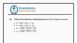
Page 9 :
46. The ratio of lateral strain to linear strain is called, (a) Modulus of Elasticity, (b) Modulus of Rigidity, (c) Bulk Modulus, (d) Poisson’s Ratio, (Ans:d), , 48. A perfectly elastic body, (a) Can move freely, (b) Has perfectly smooth surface, (c) Is not deformed by any external surface, (d) Recovers its original size and shape when the deforming force is removed., (Ans:d), , 49. The value of Poison’s ratio depends upon, (a) Nature of load, tensile or compressive, (b) Magnitude of load, (c) Material of the test specimen, (d) Dimensions of the test specimen, (Ans:c), 50. When a section is subjected to two equal and opposite forces tangentially to the, section, the stress produced is known as, (a) Tensile stress
Page 10 :
(b) Lateral stress, (c) Shear stress, (d) No stress, (Ans:c), 51. Which of the following is a dimensionless quantity?, (a) Shear stress, (b) Poison’s ratio, (c) Strain, (d) Both (b) and (c), (Ans:d), 52. Percentage elongation during tensile test is indication of, (a) Ductility, (b) Malleability, (c) Creep, (d) Rigidity, (Ans:a), 53. Brittleness is opposite to, (a) Toughness, (b) Plasticity, (c) Malleability, (d) None of these, (Ans:b)
Page 11 :
54.The statement : stress is proportional to strain, i.e. the Hooke’s law holds good upto, (a) Elastic Limit, (b) Proportional Limit, (c) Plastic Limit, (d) Yield point, (Ans:b), 55. The limit beyond which the material does not behave elastically is known as, (a) Proportional limit, (b) Elastic limit, (c) Plastic limit, (d) Yield Point, (Ans:b), 56. When mild steel is subjected to a tensile load, its fracture will conform to, (a) Star shape, (b) Granular shape, (c) Cup and cone shape, (d) Fibrous shape, (Ans:c), 57. When a wire is stretched to double in length, the longitudinal strain produced in it is, (a) 0.5, (b) 1.0, (c) 1.5, (d) 2.0
Page 12 :
(Ans:b), 58. The length of a wire is increased by 1 mm on the application of a certain load. In a, wire of the same material but of twice the length and half the radius, the same force will, produce an elongation of, (a) 0.5 mm, (b) 2 mm, (c) 4 mm, (d) 8 mm, (Ans:d), , 63. When a bar is subjected to a change of temperature and its longitudinal deformation is, prevented, the stress induced in the bar is, (a) Tensile, (b) Compressive, (c) Shear, (d) Temperature, (Ans:d), 64. When a bar is subjected to increase in temperature and its deformation is prevented,, the stress induced in the bar is, (a) Tensile, (b) Compressive, (c) Shear, (d) None of the above, (Ans:b)
Page 13 :
65. In a composite body, consisting of two different materials………..will be same in, both materials., (a) Stress, (b) Strain, (c) Both stress and strain, (d) None of these, (Ans:b), , 66. Nature of shear stress is, (a) Positive, (b) Negative, (c) Positive as well as negative, (d) None, (Ans: c), 67. Shear stress causes, (a) Deformation, (b)Elongation, (c) Contraction, (d) None, (Ans: d), 68. Shear stress causes, (a) Deformation, (b) Distortion, (c) Displacement, (d) None, (Ans: b), 69. Shear strain is a, (a) Linear strain, (b) Parabolic strain, (c) Logarithmic strain, (d) None, (Ans: d)
Page 14 :
70. Shear strain is a, (a) Linear strain, (b) Parabolic strain, (c) Angular strain, (d) None, (Ans: c), 71. Linear stress strain curve is for a, (a) Load ∞ displacement, (b) Load ∞ ( 1/displacement), (c) Load = ( displacement)2, (d) None, (Ans: a), 72. Parabolic stress strain curve is for a, (a) Load ∞ displacement, (b) Load ∞ ( 1/displacement), (c) Load = ( displacement)2, (d) None, (Ans: d), 73. Unit stress after load application is based on, (a) Original area of cross section, (b) Changing area of cross section, (c) Final area of cross section under maximum load, (d) None, (Ans: a), 74. Real stress after load application is based on, (a) Original area of cross section, (b) Changing area of cross section, (c) Final area of cross section under maximum load, (d) None, (Ans: b), 75. Which stress strain curve is more steep, (a) For a ductile material, (b) For a brittle material, (c) For a pure metal, (d) None, (Ans: b), 76. Breaking stress is, (a) greater than the ultimate stress, (b) Less than the ultimate stress
Page 15 :
(c) equal to the ultimate stress, (d) None, (Ans: a), 77. Stress under suddenly applied load is, (a) Three times than the gradually applied load, (b) equal to the that due to gradually applied load, (c) Less than that due to gradually applied load, (d) none, (Ans: d), 78. With the increase of carbon content in steel, maximum stress, (A) Increases, (b) Decreases, (C) Remains the same, (d) none, (Ans: a), 79. The property of the material which allows it to be drawn into smaller section, (a) Plasticity, (b) Ductility, (c) Elasticity, (d) Malleability, (Ans: b), 80. Rapture stress is, (a) Breaking stress, (b) Load at the braking point/A, (c) Load at the breaking point/Neck area, (d) Maximum Stress, (Ans: c), , Principal stresses and strains, , Multiple Choice Questions (MCQ), 1., , Which of the following is maximum in the principal Plane, (a) Normal stress (b) Shear stress (c) shear strain (d) None of the above, , 2., , The shear stress in the principal plane is, (a) Zero (b) Maximum (c) Minimum (d) Average, , 3., , The principal plane for the tensile load along the length of the bar is
Page 16 :
(a), (b), (c), (d), 4., , 5, , Perpendicular to the tensile load, Parallel to the tensile load, 45o to the tensile load, 30o to the tensile load, , Two Triangular wedges are glued together as shown in the following figure. The stress acting, normal to the interface, σn is, , (a) Zero MPa (b) 100 MPa (c) 50 MPa (d) 60 MPa, ., The major and minor principal stresses at a point are 3 MPa and -3 MPa respectively. The maximum, shear stress at the point is, (a) 3 MPa (b) Zero MPa (c)6 MPa (d) 9MPa, , 6, , Consider the following statements:, I. On a principal plane, only normal stress acts., II. On a principal plane, both normal and shear stresses act., III. On a principal plane, only shear stress acts., IV. Isotropic state of stress is independent of frame of reference., The TRUE statements are, , (a) I and IV (b) II (c) II and IV (d) II and III, 7., , An axially loaded bar is subjected to a normal stress of 173 MPa. The shear stress in the bar is, (A) 75 MPa (B) 86.5 MPa (C) 100 MPa(D) 122.3 MPa, , 8., , For the plane stress situation shown in the figure, the maximum shear stress and the plane on, which it acts are:
Page 17 :
(A) -50 MPa, on a plane 45o clockwise w.r.t. x-axis, (B) -50 MPa, on a plane 45o anti-clockwise w.r.t. x-axis, (C) 50 MPa, at all orientations, (D) Zero, at all orientations, 9., , What is the unit of the Principal Stress and Principal strain, (a) N/mm2 and mm (b) N and mm (c) N/mm and mm2 (d) N/mm2 and No unit, , 10., , The angle between the planes of the maximum and minimum principal stress are, (a) 90o (b) 45o (c)30o (d) 0o, , 11., , The maximum principal stress is given by, , 1, x, 2, 1, (b) x, 2, 1, x, (c), 2, 1, (d) x, 2, (a), , 12., , y , , 1, 2, 1, y , 2, 1, y , 2, 1, y , 2, , , , y, , x 4 2, , , , y, , x 4 2, , , , x, , y 4 2, , , , y, , x 2 2, , 2, , 2, , 2, , 2, , The minimum principal stress is given by, , 1, x, 2, 1, (b) x, 2, 1, x, (c), 2, 1, (d) x, 2, (a), , y , , 1, 2, 1, y , 2, 1, y , 2, 1, y , 2, , , , y, , x 4 2, , , , y, , x 4 2, , , , x, , y 4 2, , , , y, , x 2 2, , 2, , 2, , 2, , 2
Page 18 :
13., , The principal plane in the 2D is given by, , y x, 2, 2, (b) tan 2 , y x, 2, (c) tan 2 , y x, 2, (d) tan 2 , x y, (a) tan 2 , , 14., , The principal plane in the 2D in terms of sine of the angle is given by, (a) sin 2 , (b) sin 2 , (c) sin 2 , (d) sin 2 , , , , , , , , , 2, , x 4 2, 2, , y, , 2, , x 4 2, 2, , y, , 2, , x 4 2, 2, , y, , 2 2, , x 4 2, 2, , y, , 15., , The state of STRESS at a point is a ____________________(a) Scalar, (b) Vector, (c) Tensor, (d) All the above, , 16, , How many components of the stress is required to completely define the stress at a point in 3D ?, (a) 3 (b) 5 (c) 7 (d) 9, , 17., , The Cauchy stress tensor is used for stress analysis of material bodies experiencing, (a) Small Deformation, (b) Large Deformation, (c) Finite Deformation, (d) Medium Deformation, , 18., , The Number of independent stress components in 3D are, (a) 2 (b) 4 (c) 6 (d) 9, , 19, , Which of the following principles demonstrates that stress at a point is symmetric?, (a) Law of Conservation of Linear momentum, (b) Law of Conservation of angular momentum
Page 19 :
(c) Law of Conservation of mass, (d) Law of Conservation of energy, 20, , The plane stress condition can be applied to, (a) Thick Element, (b) Thin Element, (c) 3D element, (d) 3D thick Element, , 21, , The plane strain condition can be applied to, (a) Thick Element, (b) Thin Element, (c) 3D element, (d) 3D thick Element, , 22, , The stress at a point is considered plane stress if one of the principal stress is, (a) Zero (b) Maximum (c) Minimum (d) Average, , 23, , For plane stress conditions the number of independent stress components are, (a) 1 (b) 2 (c) 3 (d) 4, , 24., , For plane strain conditions the number of independent stress components are, (a) 1 (b) 4 (c) 6 (d) 7, , 25, , For plain strain conditions, the principal strain along longest dimension is, (a) Maximum (b) Minimum (c) Zero (d) None of the above, , 26, , Normal Stress component at a plane passing through a point in a continuum under plane stress, conditions is, , 1, x, 2, 1, (b) n x, 2, 1, (c) n x, 2, 1, (d) n x, 2, (a) n , , 27, , y , , 1, y, 2, 1, y y, 2, 1, y y, 2, 1, y y, 2, , x cos 2 xy sin 2, , x cos 2 xy sin 2, x sin 2 xy cos 2, x cos xy sin , , (e), Shear Stress component at a plane passing through a point in a continuum under plane stress, conditions is, , 1, y x sin 2 xy cos 2, 2, 1, (b) n y x sin 2 xy cos 2, 2, 1, (c) n y x sin xy cos , 2, (a) n
Page 20 :
(d) n , , 1, y x cos 2 xy sin 2, 2, , 28, , The Maximum shear stress occurs at =, (a) 30o(b) 45o(c) 90o (d) 180o, , 29, , The Maximum shear stress is given by, (a) max , , y , , (b) max, , y , , (c) max, (d) max, 30., , 1, x, 2, 1, x, 2, 1, x, 4, 1, x, 4, , y , y , , The Minimum shear stress is given by, (a) min , , 1, x y , 2, , 1, x y , 2, 1, x y , 4, 1, x y , 4, , (b) min , (c) min, (d) min, 31., , In the Biaxial stress condition and if stress along x and y axis are same then the shear stress is, (a) max x (b) max , , x, 2, , (c) max x (d) max x y, , 32., , For pure shear conditions on a 2D element, The normal stress is _____________ when is, between 0o to 90o, (a) Tensile (b) Compressive (c) Zero (d) None of the above., , 33., , For pure shear conditions on a 2D element, The normal stress is _____________ when is, between 90o to 180o, (a) Tensile (b) Compressive (c) Zero (d) None of the above., , 34., , For pure shear conditions on a 2D element, The Shear stress is zero at =, (a) 30o(b) 45o (c) 60o (d) 90o, , 35., , For the biaxial and shear stresses acting on a 2D element, The maximum shear stress plane is, _____- to the principal normal stress planes, (a) 30o (b) 45o (c) 60o (d) 90o, , 36., , The state of stress at a point under the plane stress condition is=40 MPa, =100 MPa, and =40
Page 21 :
37., , MPa. The radius of the Mohr’s circle representing the given state of stress in MPa is, (a) 40 (b) 50 (c) 60 (d) 100, If the principle stresses in a plane stress problem, are 100 MPa and 40 MPa, then the magnitude, of the maximum shear stress (MPa) will be, (a) 20 (b) 30 (c) 300 (d)70, , 38., , A solid circular shaft of diameter 100 mm is subjected to an axial stress of 50 MPa. It is further, subjected to a torque of 10 kNm. The maximum principle stress experienced on the shaft is, closest to, (a) 41 MPa(b) 82 MPa(c) 164 MPa(d) 204 MPa, , 39., , A two dimensional fluid element rotates like a rigid body. At a point within the element, the, pressure is 1 unit. Radius of the Mohr’s circle, characterizing the state of stress at the point, is, (a) 0.5 unit (b) 0 unit(c) 1 unit (d)2 unit, , 40., , A shaft subjected to torsion experiences a pure shear stress on the surface. The maximum, principle stress on the surface which is at 45° to the axis will have a value, (a) cos 45 o (b) 2 cos 45 o (c) cos 2 45 o (d) 2 sin 45 o cos 45 o, , 41, , The figure shows the state of stress at certain point in a stresses body. The magnitudes of normal, stresses in x and y direction are 100 MPa and 20 MPa respectively. The radius of Mohr’s stress, circle representing this state of stress is, , (a) 120 MPa(b) 60 MPa (c) 40 MPa (d) 80 MPa, 42., , The Mohr’s circle of plane stress for a point in a body is shown. The design is to be done on the, basis of the maximum shear stress theory for yielding. Then, yielding will just begin if the, designer chooses a ductile material whose yield strength is, , (a) 45 MPa (b) 50 MPa(c) 90 MPa (d) 100 MPa, 43., , The state of stress at a point “P” in a two dimensional loading is such that the Mohr’s circle is a
Page 22 :
point located at 175 MPa on the positive normal stress axis., Determine the maximum and minimum principle stresses respectively from the Mohr’s circle, (a) +175 MPa, -175 MPa(b) +175 MPa, +175 MPa (c) 0,-175 MPa (d) 0,0, 44., , The state of stress at a point on an element is shown in figure (a). The same state of stress is, shown in another coordinate system in figure (b)., , The components (τxx,τyy,τxy) are given by, , p, , (a) , , 2, , 45., , 46., , , , p, 2, , p, , 0 (b) 0 , 2, , , , 0 (c) 0 0, , , p, p (d) , 2, , , , , p, 2, , , 0, , , The state of stress at a point is given by σx=−6MPa, MPa, σy=4 MPa, and τxy==-8 MPa.The, maximum tensile stress (in MPa) at the point is ________, (a) 8.45 (b)7.45 (c) 5.5 (d)2.3, The state of stress at a point under plane stress condition is, σxx=40MPa, σyy=100MPa and τxy=40MPa, The radius of the Mohr’s circle representing the given state of stress in MPa is, (a) 50 (b) 60 (c)40 (d) 100, , 47., , The state of plane-stress at a point is given by σx =−200MPa, σy = 100MPa and τ= 100MPa ., The maximum shear stress in MPa is, (a) 111.8 (b)150.1 (c)180.3 (d)223.6, , 48, , In Mohr’s Circle, the X –axis is, (a) Normal Stress (b) Shear stress (c) Oblique Stress (d) None of the above, , 49., , In Mohr’s Circle, the Y –axis is, (a) Normal Stress (b) Shear stress (c) Oblique Stress (d) None of the above, , 50., , For 2D Cases, the state of stress tensor can be represented by, (a) 2x2 Matrix (b) 3x3 Matrix (c) 2x3 matrix (d) 3x 2 matrix, , 51., , For 3D Cases, the state of stress tensor can be represented by, (a) 2x2 Matrix (b) 3x3 Matrix (c) 2x3 matrix (d) 3x 2 matrix, , 52., , Which of the following can be obtained from the Mohr’s Circle
Page 23 :
(a) Principal Stress (b) Moment of inertia (c) Stiffness (d) Damping, 53., , Principal stress is _____________ to the Principal plane, (a) Tangential (b) 45o (c) Normal (d) 180o, Which of the following is the Graphical Representation of the Stress at a point, (a) Mohr’s Circle (b) Cauchy’s Stress quadratic (c) Lame’s Stress ellipsoid (d) All the above, , 54, , 55, , The eigen values of the Cauchy stress tensor is, (a) Principal stress (b) Normal stress (c) Shear stress (d) Strain, , 56, , Which of the following are used to measure the stress, (a) Piola-Kirchoff stress (b) Biot Stress tensor (c) Krichoff Stress tensor (d) All the above, In Morh Circle, the intersection of circle and x-axis is, (a) Shear stress (b) Principal stresses (c) Normal stress at any plane (d) Shear stress at any, plane, , 57., , 58., , In a 2D stress condition, the normal stress along x and y are 90MPa and -60MPa, respectively., And the shear stress is 20MPa. What is the centre of the Mohr’s Circle?, (a) 30MPa (b) 15 MPa (c)45 MPa (d) 60 MPa, , 59., , In a 2D stress condition, the normal stress along x and y are 90MPa and -60MPa, respectively., And the shear stress is 20MPa. What is the radius of the Mohr’s Circle?, (a) 70 MPa (b) 77MPa (c)50 MPa (d) 10 MPa, , 60., , The centre and radius of the Mohr’s circle for a 2D stress condition is 40 Mpa and 90 MPa., What are the principal stresses for this stress conditions?, (a) 130 MPa and -50 MPa (b) 130 MPa and 50 MPa (c) -130 MPa and -50 MPa, (d) -130 MPa and 50 MPa, , Shear force and bending moment diagram, 1. The bending moment at the fixed end of a cantilever beam is, (a) Maximum, (b) Minimum, (c) Wl/2, (d) Wl, , 2. The bending moment diagram for a cantilever with point load, at the free end will be, (a) A triangle with max. height under free end, (b) A triangle with max. height under fixed end
Page 24 :
(c) A parabolic curve, (d) None of these, , 3. For a simply supported beam, loaded with point load, the B.M.D. will be, (a) A triangle, (b) A parabolic curve, (c) A cubic curve, (d) None of these, , 4. For a simply supported beam of span L, with point load W at the centre, the maximum, B.M. will be, (a) WL, (b) WL/2, (c) WL/4, (d) WL/8, , 5. For a simply supported beam of span L, loaded with U.D.L. w/m over the whole span,, the maximum B.M will be, (a) wL/4, (b) wL2/8, (c) wL2/4, (d) WwL2/2, , 6. At the point of contraflexure, (a) B.M is mimimum, (b) B.M is maximum, (c) B.M is either zero or changes sign, (d) None of these
Page 25 :
7. The Point of contraflexure occurs in case of, (a) Cantilever beams, (b) Simply supported beams, (c) Over hanging beams, (d) All types of beams, , 8. A cantilever beam of length of 2m carries a U.D.L. of 150 N/m over its whole span. The, maximum shear force in the beam will be, (a) 150 N, (b) 300 N, (c) 150 N-m, (d) 600 N-m, , 9. A cantilever beam of span 3m carries a point load 100 N at the free end. The maximum, B.M in the beam will be, (a) 100 N-m, (b) 300 N-m, (c) 150 N-m, (d) 600 N-m, , 10. Bending moment at supports in case of simply supported beam is always, (a) Zero, (b) Positive, (c) Negative, (d) Depends upon loading, , 11. The shear force at the centre of a simply supported beam of span l carrying a uniformly, distributed load of w per unit length over the whole span is, (a) wl
Page 26 :
(b) wl/2, (c) wl/4, (d) Zero, , 12. Shear force (F) and loading (W) are related by, (a), (b), (c), (d), , 13. Shear force (F) and bending moment (M) are related by, (a), (b), (c), (d) None of these, , 14. The bending moment diagram for a cantilever with U.D.L. over the whole span will be, (a) Triangle, (b) Rectangle, (c) Parabola, (d) Ellipse, , 15. The rate of change of bending moment is equal to, (a) Shear force, (b) Slope, (c) Deflection, (d) None of these
Page 27 :
16. In a simply supported beam carrying a uniformly distributed load over the left half span,, the point of contraflexure will occur in, (a) Left half span of the beam, (b) Right half span of the beam., (c) Quarter points of the beam, (d) Does not exist, , 17. A sudden increase or decrease in shear force diagram between any two points indicates, that there is, (a) No loading between the two points, (b) Point loads between the two points, (c) U.D.L. between the two points, (d) None of these, , 18. When the bending moment is parabolic curve between two points, it indicates that, there is, (a) No loading between the two points, (b) Point loads between the two points, (c) U.D.L. between the two points, (d) Uniformly varying load between the two points, , 19. In Fig. (1), max. S.F. will be, (a) 5 kN, (b) 10 kN, (c) 15 kN, (d) 30 kN, Figure 1
Page 28 :
20. In Fig.(1), max B.M. will be, (a) 40 kN-m, (b) 50 kN-m, (c) 60 kN-m, (d) 80 kN-m, , 21. In Fig. (1), slope of S.F.D. between B and C will be, (a) Zero, (b) 10 kN, (c) 15 kN, (d) 20 kN, , 22. In Fig. (1), slope of B.M.D. between B and C will be, (a) Zero, (b) 5 kN, (c) 20 kN, (d) 15 kN, , 23. In Fig. (2), at point B, the value of B.M will be, (a) 5 kN, (b) 10 kN, (c) Zero, (d) None of these, Figure 2, , 24. In Fig. (2), the reaction at support A will be, (a) 6 kN, (b) 2 kN, (c) 4 kN
Page 29 :
(d) None of these, , 25. In Fig. (2), the maximum B.M. will be at, (a) Support A, (b) Support B, (c) Centre of beam, (d) Under the load, , 26. In Fig. (2), the maximum B.M. will be, (a) 6 kN-m, (b) 4 kN-m, (c) 2 kN-m, (d) 8 kN-m, , 27. In Fig. (3), the slope of B.M.D. will be more for, (a) Portion AC, (b) Portion BC, (c) Will be equal, (d) None of these, Figure 3, 28. Fig. (3) gives the S.F.D. for a, (a) Cantilever beam, (b) Simply supported beam, (c) Overhanging beam, (d) Insufficient data, , 29. Corresponding to Fig. (3), the loading on the portion AD of the beam will be, (a) Uniformly distributed load, (b) Uniformly varying load
Page 30 :
(c) Point loads, (d) Cannot be said, , 30. Corresponding to Fig. (3), the maximum bending moment will be at, (a) A, (b) B, (c) C, (d) D, , 31. A beam is a structural member which is subjected to, (a) Axial tension or compression, (b) Transverse loads and couples, (c) Twisting moment, (d) No load, but its axis should be horizontal and x-section rectangular or circular, , 32. Which of the following are statically determinate beams?, (a) Only simply supported beams, (b) Cantilever, overhanging and simply supported, (c) Fixed beams, (d) Continuous beams, , 33. A cantilever is a beam whose, (a) Both ends are supported either on rollers or hinges, (b) One end is fixed and other end is free, (c) Both ends are fixed, (d) Whose both or one of the end has overhang, , 34. In a cantilever carrying a uniformly varying load starting from zero at the free end, the, shear force diagram is
Page 31 :
(a) A horizontal line parallel to x-axis, (b) A line inclined to x-axis, (c) Follows a parabolic law, (d) Follows a cubic law, , 35. In a cantilever carrying a uniformly varying load starting from zero at the free end, the, Bending moment diagram is, , (a) A horizontal line parallel to x-axis, (b) A line inclined to x-axis, (c) Follows a parabolic law, (d) Follows a cubic law, 36. In a simply supported beam, bending moment at the end, , (a) Is always zero if it does not carry couple at the end, (b) Is zero, if the beam has uniformly distributed load only, (c) Is zero if the beam has concentrated loads only, (d) May or may not be zero, , 37. 7-For any part of the beam, between two concentrated load Shear force diagram is a, , (a) Horizontal straight line, (b) Vertical straight line, (c) Line inclined to x-axis, (d) Parabola, , 38. For any part of a beam between two concentrated load, Bending moment diagram is a, , (a) Horizontal straight line
Page 32 :
(b) Vertical straight line, (c) Line inclined to x-axis, (d) Parabola, , 39. For any part of a beam subjected to uniformly distributed load, Shear force diagram is, , (a) Horizontal straight line, (b) Vertical straight line, (c) Line inclined to x-axis, (d) Parabola, , 40. For any part of a beam subjected to uniformly distributed load, bending moment, diagram is, , (a) Horizontal straight line, (b) Vertical straight line, (c) Line inclined to x-axis, (d) Parabola, , 41. A sudden jump anywhere on the Bending moment diagram of a beam is caused by, , (a) Couple acting at that point, (b) Couple acting at some other point, (c) Concentrated load at the point, (d) Uniformly distributed load or Uniformly varying load on the beam, , 42. In a simple supported beam having length = l and subjected to a concentrated load (W), at mid-point.
Page 33 :
(a) Maximum Bending moment = Wl/4 at the mid-point, (b) Maximum Bending moment = Wl/4 at the end, (c) Maximum Bending moment = Wl/8 at the mid-point, (d) Maximum Bending moment = Wl/8 at the end, , 43. In a simply supported beam subjected to uniformly distributed load (w) over the entire, length (l), total load=W, maximum Bending moment is, , (a) Wl/8 or wl2/8 at the mid-point, (b) Wl/8 or wl2/8 at the end, (c) Wl/4 or wl2/4, (d) Wl/2, , 44. In a cantilever subjected to a concentrated load (W) at the free end and having length, =l, Maximum bending moment is, (a) Wl at the free end, (b) Wl at the fixed end, (c) Wl/2 at the fixed end, (d) Wl at the free end, , 45. An axle is subjected to loads as shown in Figure 4 and the Maximum bending moment is
Page 34 :
(a) Wl, (b) W(l-a), (c) Wa, (d) W(l+a), , Figure 4, , 46. At a point in a simply supported or overhanging beam where Shear force changes sign, and = 0, Bending moment is, , (a) Maximum, (b) Zero, (c) Either increasing or decreasing, (d) Infinity, , 47. In a cantilever subjected to a combination of concentrated load, uniformly distributed, load and uniformly varying load, Maximum bending moment is, (a) Where shear force=0, (b) At the free end, (c) At the fixed end, (d) At the mid-point, , 48. Point of contra-flexure is a, , (a) Point where Shear force is maximum, (b) Point where Bending moment is maximum, (c) Point where Bending moment is zero, (d) Point where Bending moment=0 but also changes sign from positive to negative
Page 35 :
49. Point of contra-flexure is also called, , (a) Point of maximum Shear force, (b) Point of maximum Bending moment, (c) Point of inflexion, (d) Fixed end, , 50. The slope of shear force line at any section of the beam is also called, (a) Bending moment at that section, (b) Rate of loading at that section, (c) Maximum Shear force, (d) Maximum bending moment, , 51. The concavity produced on the beam section about the centre line when downward, force acts on it is called as, (a) Hogging or positive bending moment, (b) Hogging or negative bending moment, (c) Sagging or positive bending moment, (d) Sagging or negative bending moment, , 52. In axial thrust diagram, at which point bending moment is zero?, (a) Point of contra-flexure, (b) Point of inflection, (c) Both a. and b., (d) None of the above, , 53. The graphical representation of variation of axial load on y axis and position of cross, section along x axis is called as _____
Page 36 :
(a) Bending moment diagram, (b) Shear force diagram, (c) Stress-strain diagram, (d) Trust diagram, , 54. A concentrated load P acts on a simply supported beam of span L at a distance L/3 from, the left support. The bending moment at the point of application of the load is given by, (a) PL/3, (b) 2PL/3, (c) PL/9, (d) 2PL/9, 55. The graphical representation of variation of axial load on y axis and position of cross, section along x axis is called as _____, (a) Bending moment diagram, (b) Shear force diagram, (c) Stress-strain diagram, (d) Trust diagram, 56. Variation of bending moment due to concentrated loads will be, (a) Linear, (b) Parabolic, (c) Cubic, (d) None, (Ans: a), , 57. How many points of contra-flexure can be there in a simply supported beam, (a) One, (b) Two, (c) Three
Page 37 :
(d) None, , 58. How many points of contra-flexure can be there in beam hinged at both ends, (a) One, (b) Two, (c) Three, (d) None, , 59. How many points of contra-flexure can be there in beam having one overhang, (a) One, (b) Two, (c) Three, (d) None, , 60. How many points of contra-flexure can be there in beam having two overhangs, (a) One, (b) Two, (c) Three, (d) None, , 61. At the point of contra flexture, the bending moment is, (a) Maximum, (b) Minimum, (c) Zero, (d) None
Page 38 :
62. At the point of contra flexture, the shear force in the shear force diagram will be, (a) Maximum, (b) Minimum, (c) Zero, (d) None, , 63. Maximum shear force in a S.S. beam having a concentrated load at the centre will be, (a) W, (b) W/2, (c) W/4, (d) None, , 64. Maximum shear force in a S.S. beam having a UDL over entire length will be, (a) wL/2, (b) wL/4, (c) wL/8, (d) None, , 65. Maximum shear force in a cantilever beam having a UDL over entire length will be, a) wL/2, (b) wL, (c) wL/4, (d) None, , 66. A beam is a simply supported beam when its movement is restricted in _______ in both, the ends, (a) One way, (b) Two ways, (c) Three ways
Page 39 :
(d) None, , 67. A beam is a hinged beam when its movement is restricted in_______ on both the ends, (a) One way, (b) Two ways, (c) Three ways, (d) None, , 68. A beam is a fixed beam when its movement is restricted in_______ on both the ends, (a) One way, (b) Two ways, (c) Three ways, (d) None, , 69. Movement of the free end of a cantilever is restricted in_______ from one end, (a) One way, (b) Two ways, (c) Three ways, (d) None, , 70. An overhanging beam can have, (a) One overhang, (b) Three overhangs, (c) Five overhangs, (d) None, , 71. An overhanging beam can have, (a) Zero overhang, (b) Three overhangs
Page 40 :
(c) Two overhangs, (d) None, , 72. A continuous beam is one which has, (a) One support, (b) Two supports, (c) Three supports, (d) None, (Ans: c), , 73. Variation of shear force due to UDL will be, (a) Linear, (b) Parabolic, (c) Cubic, (d) None, , 74. Variation of bending moment due to UDL will be, (a) Linear, (b) Parabolic, (c) Cubic, (d) None, , 75. A bending moment at any point of a beam is, (a) Net bending moment on left of the point, (b) Maximum bending moment on right of the point, (c) Minimum bending moment on one side of the point, (d) None
Page 41 :
76. Variation of shear stress in a beam has, (a) Parabolic variation, (b) Linear variation, (c) Cubical variation, (d) None, , 77. A beam is designed on the basis of, (a) Shear force, (b) Bending moment, (c) Shear force as well as bending moment, (d) None, , 78. Bending stress will be least at the extreme fibres for, (a) Maximum area of cross section, (b) Maximum moment of inertia, (c) Maximum section modulus, (d) None, , 79. Moment of resistance of a beam should be, (a) Greater than the bending moment, (b) Less than the bending moment, (c) Two times the bending moment, (d) None, , 80. Variation of bending strain in a beam has, (a) Parabolic variation, (b) Linear variation, (c) Cubical variation
Page 42 :
(d) None, , 81. Bending stresses in a beam are maximum at the, (a) Centeroidal axis, (b) Extreme fibres, (c) Geometric axis, (d) None, , 82. Shear stress in a beam is maximum at the, (a) Centeroidal axis, (b) Extreme fibres, (c) Geometric axis, (d) None, , 83. Bending stresses in a beam is zero at the, (a) Centroidal axis, (b) Extreme fibers, (c) Geometric axis, (d) None, , 84. Shear stress in a beam is zero at the, (a) Centeroidal axis, (b) Extreme fibres, (c) Geometric axis, (d) None, , 85. Variation of bending stresses in a beam have, (a) Parabolic variation, (b) Linear variation
Page 43 :
(c) Cubical variation, (d) None, , 86. Which moment is considered as positive moment, (a) Hogging, (b) Sagging, (c) Clockwise, (d) None, , 87. A shear force at any point of a beam is, (a) Maximum vertical force on left of the point, (b) Maximum vertical force on right of the point, (c) Net vertical force on one side of the point, (d) None, , 88. Tensile and compressive stresses in a beam of symmetrical section are, (a) σt = σc, (b) σt > σc, (c) σt < σc, (d) None, , 89. Tensile and compressive stresses in a beam of un-symmetrical section are, (a) σt = σc, (b) σt =0, (c) σc =0, (d) None, , 90. At the points of bending moment changes sign, shear force will be, (a) Maximum
Page 45 :
(b) Minimum, (c) Zero, (d) None, , 96. At the supports of a simply supported beam, bending moment will be, (a) Maximum, (b) Minimum, (c) Zero, (d) None, (Ans:c), , 97. At the supports of a simply supported beam, shear forces will be, (a) Maximum, (b) Minimum, (c) Zero, (d) None, , 98. In case of a cantilever beam, bending moment at the free end will be, (a) Maximum, (b) Minimum, (c) Zero, (d) None, , 99. In case of a cantilever beam, bending moment at the fixed end will be, (a) Maximum, (b) Minimum, (c) Zero, (d) None
Page 46 :
100., , In case of a cantilever beam, shear force at the fixed end will be, , (a) Maximum, (b) Minimum, (c) Zero, (d) None, , 101., , In case of a cantilever beam having concentrated loads, bending moment, , variation will be, (a) Linear, (b) Parabolic, (c) Cubic, (d) None, , 102., , In case of a cantilever beam having UDL, bending moment variation will be, , (a) Linear, (b) Parabolic, (c) Cubic, (d) None, , 103., , In case of a cantilever beam having concentrated loads, shear force variation will, , be, (a) Linear, (b) Parabolic, (c) Cubic, (d) None, , 104., be, , In case of a cantilever beam having concentrated loads, shear force variation will
Page 47 :
(a) Linear, (b) Parabolic, (c) Cubic, (d) None, , 105., , In case of a cantilever beam having UDL, shear force variation will be, , (a) Linear, (b) Parabolic, (c) Cubic, (d) None, , 106., , Maximum bending moment in a S.S. beam having a concentrated load at the, , centre will be, (a) WL, (b) WL/2, (c) WL/4, (d) None, , 107., , Maximum bending moment in a S.S. beam having a UDL over entire length will, , be, (a) wL2/2, (b) wL2/4, (c) wL2/8, (d) None, , 108., , Maximum bending moment in a cantilever beam having a UDL over entire length, , will be, (a) wL2/2, (b) wL2/4
Page 49 :
Q.NO Option Q.NO Option Q.NO Option Q.NO Option Q.NO Option Q.NO Option, 1, a, 11, d, 21, a, 31, b, 41, a, 51, b, 2, b, 12, a, 22, c, 32, b, 42, a, 52, c, 3, a, 13, b, 23, c, 33, b, 43, a, 53, d, 4, c, 14, c, 24, c, 34, c, 44, b, 54, d, 5, b, 15, a, 25, d, 35, d, 45, c, 55, d, 6, c, 16, d, 26, b, 36, a, 46, a, 56, a, 7, c, 17, b, 27, a, 37, a, 47, c, 57, d, 8, b, 18, c, 28, b, 38, c, 48, d, 58, d, 9, b, 19, c, 29, a, 39, c, 49, c, 59, a, 10, a, 20, b, 30, c, 40, d, 50, b, 60, b, , Q.NO Option Q.NO Option Q.NO Option Q.NO Option Q.NO Option Q.NO Option, 61, c, 71, c, 81, b, 91, b, 101, a, 111, a, 62, a, 72, c, 82, a, 92, a, 102, b, 112, b, 63, b, 73, a, 83, a, 93, c, 103, d, 64, a, 74, b, 84, b, 94, c, 104, d, 65, b, 75, a, 85, b, 95, a, 105, a, 66, a, 76, a, 86, b, 96, c, 106, c, 67, b, 77, c, 87, c, 97, a, 107, c, 68, c, 78, c, 88, a, 98, c, 108, a, 69, c, 79, a, 89, d, 99, a, 109, c, 70, a, 80, b, 90, a, 100, a, 110, b, , Bending and shearing stresses, 1. Moment of inertia acting on a semi-circle about symmetrical axes is given as _______, a. 1.57 r4, b. 0.055 r4, c. 0.392 r4, d. 0.11 r4, Answer: c, 2. What is the moment of inertia acting on a rectangle of width 15 mm and depth 40 mm, about base by using theorem of parallel axes?, a. 320 x 103 mm4, b. 300 x 103 mm4, c. 240 x 103 mm4, d. 80 x 103 mm4, Answer: a
Page 50 :
3. What is the S.I. unit of sectional modulus?, a. mm4, b. mm3, c. mm2, d. m, Answer: b, 4. What is the moment of inertia acting on a circle of diameter 50 mm?, a. 122.71 x 103 mm4, b. 306.79 x 103 mm4, c. 567.23 x 103 mm4, d. 800 x 103 mm4, Answer: b, 5. Which of the following relations is used to represent theorem of perpendicular axes?, (H = Vertical axis, I = Moment of inertia and K = Radius of gyration), a. IPQ = Ixx + AH2, b. IPQ = Ixx + Ak2, c. Izz = Ixx + Iyy, d. Izz + Ixx + Iyy = 0, Answer: c, 6. What is the moment of inertia acting on a semicircle of radius 20 mm about the, asymmetrical axes?, a. 125.663 x 103 mm4, b. 17600 mm4, c. 1500 mm4, d. 8800 mm4, Answer: b, 7. What is the product of sectional modulus and allowable bending stress called as?, a. Moment of inertia, b. Moment of rigidity, c. Moment of resistance, d. Radius of gyration, Answer: c, 8. A uniformly distributed load of 20 kN/m acts on a simply supported beam of rectangular, cross section of width 20 mm and depth 60 mm. What is the maximum bending stress, acting on the beam of 5m?, a. 5030 Mpa, b. 5208 Mpa, c. 6600 Mpa, d. Insufficient data, Answer: b
Page 51 :
9. The bending formula is given as _____, a. (M/E) = (σ/y) = (R/I), b. (M/y) = (σ/I) = (E/R), c. (M/I) = (σ/y) = (E/R), d. none of the above, Answer: c, 10. Which of the following laminas have same moment of inertia (Ixx = Iyy), when passed, through the centroid along x-x and y-y axes?, a. Circle, b. Semi-circle, c. Right angle triangle, d. Isosceles triangle, Answer: a, 11. What is the average shear stress acting on a rectangular beam, if 50 N/mm2 is, the maximum shear stress acting on it?, a. 31.5 N/mm2, b. 33.33 N/mm2, c. 37.5 N/mm2, d. 42.5 N/mm2, Answer: b, 12. The ratio of maximum shear stress to average shear stress is 4/3 in _______, a. circular cross-section, b. rectangular cross-section, c. square cross-section, d. all of the above, Answer: a, 13. What is the shear stress acting along the neutral axis of triangular beam section, with, base 60 mm and height 150 mm, when shear force of 30 kN acts?, a. 15.36 N/mm2, b. 10.6 N/mm2, c. 8.88 N/mm2, d. Insufficient data, Answer: c, 14. A circular pipe is subjected to maximum shear force of 60 kN. What is the diameter of, the pipe if maximum allowable shear stress is 5 Mpa?, a. 27.311 mm, b. 75.56 mm, c. 142.72 mm, d. 692.10 mm, Answer: c
Page 52 :
15. A square object of 4 mm is subjected to a force of 3000 N. What is the maximum, allowable shear stress acting on it?, a. 250.14 mm2, b. 281.25 mm2, c. 400.32 mm2, d. 500 mm2, Answer: b, 16. The average shear stress in a beam of circular section is _______ times the maximum, shear stress., a. 0.75, b. 1.5, c. 4/3, d. equal, Answer: a, 17. What is the shear stress acting along the neutral axis, over a triangular section?, a. 2.66 (S/bh), b. 1.5 (S/bh), c. 0.375 (S/bh), d. None of the above, Answer: a, 18. Maximum shear stress in a triangular section ABC of height H and base B occurs at, _________, a. H, b. H/2, c. H/3, d. neutral axis, Answer: b, 19. The shear stress acting on the neutral axis of a beam is _____, a. maximum, b. minimum, c. zero, d. none of the above, Answer: a, 20. Which of the machine component is designed under bending stress?, a. Shaft, b. Arm of a lever, c. Key, d. Belts and ropes, Answer: b
Page 53 :
21. For bending equation to be valid, radius of curvature of the beam after bending should, be, a. Equal to its transverse dimensions, b. Infinity, c. Very large compared to its transverse dimensions, d. Double its transverse dimensions, Answer: c, 22. Neutral axis of a beam always coincides with, a. Axis passing through bottom of beam, b. Axis passing through height h/2 from bottom, c. Axis passing through height h/3 from bottom, d. Axis passing through centroid, Answer: d, 23. If depth of a beam is doubled then changes in its section modulus, a. Will remain same, b. Will decrease, c. Will be doubled, d. Will increase by 4 times, Answer: d, 24. A flitched beam has, a. Common neutral axis & both materials bend independently, b. Common neutral axis & both materials has common R (Radius of curvature), c. Two neutral axis & both materials has common R (Radius of curvature), d. Two neutral axis & both materials bend independently, Answer: b, 25. In a T-section beam, the bending stress distribution will be as shown, , Answer: b, 26. In a channel section beam, bending stress distribution will be
Page 54 :
Answer: a, 27. The strength of a beam depends upon, (a) Its section modulus, (b) Permissible bending stress, (c) Both (a) and (b), (d) None of these, Answer: a, 28. Shear stress in the beam acting on the cross section is, (a) Normal to the cross section, (b) Tangential to the cross section, (c) Neither normal nor tangential, (d) None, Answer: b, 29. Shear stress variation is, (a) Linear, (b) Polynomial, (c) Parabolic, (d) None, Answer: c, 30. For a beam of rectangular cross section, the ratio τmax/ τav is, (a) 2, (b) 1, (c) 1.5, (d) None, Answer: c, 31. Shear stress is zero at the, (a) Outermost fiber, (b) Central fiber
Page 55 :
(c) Neither outermost nor central fiber, (d) None, Answer: a, 32. Shear stress is maximum at the, (a) Outermost fiber, (b) Central fiber, (c) Neither outermost nor central fiber, (d) None, Answer: b, 33. Shear stress in a I-section beam is maximum art the, (a) Outermost fiber, (b) At the junction of web and flange, (c) Central fiber, (d) None, Answer: b, 34. For a beam of triangular cross section, the ratio τmax/ τav is, (a) 3/2, (b) 4/2, (c) 5/2, (d) None, Answer: a, 35. Shear stress causes, (a) Deformation, (b) Distortion, (c) Deformation as well as distortion, (d) None, Answer: b, 36. Variation of bending stresses in a beam have, (a) Parabolic variation, (b) Linear variation, (c) Cubical variation, (d) None, Answer: b
Page 56 :
37. Bending stress will be least at the extreme fibres for, (a) Maximum area of cross section, (b) Maximum moment of inertia, (c) Maximum section modulus, (d) None, Answer: c, 38. Moment of resistance of a beam should be, (a) Greater than the bending moment, (b) Less than the bending moment, (c) Two times the bending moment, (d) None, Answer: a, 39. Variation of bending strain in a beam has, (a) Parabolic variation, (b) Linear variation, (c) Cubical variation, (d) None, Answer: b, 40. Tensile and compressive stresses in a beam of symmetrical section are, (a) σt = σc, (b) σt > σc, (c) σt < σc, (d) None, Answer: a, 41. When a simply supported beam is loaded with a point load at the centre, the maximum, tensile stress is developed on the, (a) Top fibre, (b) Bottom fibre, (c) Neutral axis, (d) None of these, Answer: b
Page 57 :
42. The section modulus of a circular section about an axis passing through its centre is, (a), , (b), (c), (d), Answer: c, , 43. In a simply supported beam loaded with U.D.L over the whole section, the bending, stress is …………. at top and ………….. at bottom., (a) Compressive, tensile, (b) Tensile, compressive, (c) Tensile, zero, (d) Compressive, zero, Answer: a, , 44. The section modulus (Z) is given by, (a), (b), (c), (d), Answer: b, , 45. When a beam is subjected to a bending moment the strain in a layer is …………the, distance from the neutral axis., (a) Independent of, (b) Directly proportional to, (c) Inversely proportional to, (d) None of these
Page 58 :
Answer: b, , 46. A beam of uniform strength has, a. same cross-section throughout the beam, b. same bending stress at every section, c. same bending moment at every section, d. same shear stress at every section, Answer: b, 47. In a simple bending theory, one of the assumption is that the material of the beam is, isotropic. This assumption means that the, a. normal stress remains constant in all directions, b. normal stress varies linearly in the material, c. elastic constants are same in all the directions, d. elastic constants varies linearly in the material, Answer: c, 48. A beam of T-section is subjected to a shear force of F. The maximum shear force will, occur at the, a. top of the section, b. bottom of the section, c. neutral axis of the section, d. junction of web and flange, Answer: c, 49. The section modulus of a rectangular section about an axis through its C.G., is, a. b/2, b. d/2, c. bd2/2, d. bd2/6, Answer: d, 50. In a simple bending theory, one of the assumption is that the plane sections before, bending remain plane after bending. This assumption means that, a. stress is uniform throughout the beam, b. strain is uniform throughout the beam, c. stress is proportional to the distance from the neutral axis, d. strain is proportional to the distance from the neutral axis, Answer: d
Page 59 :
Torsion of shafts, 1. Magnitude of shear stress induced in a shaft due to applied torque varies from, a. Maximum at centre to zero at circumference., b. Maximum at centre to minimum (not-zero) at circumference., c. Zero at centre to maximum at circumference., d. Minimum (not zero) at centre to maximum at circumference., ANSWER: (c) Zero at centre to maximum at circumference., 2. The variation of shear stress in a circular shaft subjected to torsion is, a. Linear, b. Parabolic, c. Hyperbolic., d. Uniform., ANSWER:(a) Linear, 3. The relation governing the torsional torque in circular shafts is, a. T/r=τ/l=Gθ/J, b. T/J=τ/r=Gθ/l, c. T/J=τ/l=Gθ/r, d. T/l=τ/r=Gθ/J, ANSWER:(b) T/J=τ/r=Gθ/l, , 4. Torsional rigidity of a shaft is defined as, a. G/J, b. GJ, c. TJ, d. T/J, ANSWER:(b) T/J=τ/r=Gθ/l
Page 60 :
5. Torsional rigidity of a shaft is given by, a. Gl/θ, b. Tθ, c. Tl/θ, d. T/l, ANSWER:(c) Tl/θ, , 6. A solid shaft of same cross sectional area and of same material as that of a hollow shaft, can resist, a. Less torque., b. More torque., c. Equal torque., d. Unequal torque., ANSWER:(a) Less torque, , 7. Angle of twist of a circular shaft is given by, a. GJ/Tl, b. Tl/GJ., c. TJ/Gl., d.TG/Jl., ANSWER:(b) Tl/GJ., , 8. Maximum shear stress of a solid shaft is given by, a. 16T/πd, b. 16T/πd2, c. 16T/πd3, d. 16T/πd4, ANSWER:(c) 16T/πd3
Page 61 :
9. The ratio of maximum bending stress to maximum shear stress on the cross section when, a shaft is simultaneously subjected to a torque T and bending moment M,, a. T/M, b. M/T, c. 2T/M, d. 2M/T, ANSWER:(d) 2M/T, , 10. Maximum shear stress in a hollow shaft subjected to a torsional moment is at the, a. Middle of thickness., b. At the inner surface of the shaft., c. At the outer surface of the shaft., d. At the middle surface of the shaft., ANSWER:(c) At the outer surface of the shaft, , 11. The ratio of strength of a hollow shaft to that of a solid shaft subjected to torsion if both, are of the same material and of the same outer diameters, the inner diameter of hollow, shaft being half of the outer diameter is, a. 15/16, b. 16/15, c. 7/8, d. 8/7, ANSWER:(a) 15/16, , 12. Ratio of diameters of two shafts joined in series is 2. If the two shafts have the same, material and the same length the ratio of their angles of twist is
Page 62 :
a. 2, b. 4, c. 8, d. 16, ANSWER:(d) 16, , 13. Ratio of diameters of two shafts joined in series is 2. If the two shafts have the same, material and the same length the ratio of their shear stresses is, a. 2, b. 4, c. 8, d. 16, ANSWER: (c) 8, 14. For two shafts joined in series, the --------------- in each shaft is same., a. shear stress., b. Angle of twist, c. torque, d. torsional stress., ANSWER: (c) torque, , 15. For two shafts joined in parallel, the --------------- in each shaft is same., a. shear stress., b. Angle of twist, c. torque, d. torsional stress.
Page 63 :
ANSWER:(b) Angle of twist, 16. The shafts are made of, a. mild steel, b. alloy steel, c. copper alloys, d. cast iron., ANSWER: (d). cast iron, , 17. The shafts are designed on the basis of, a. strength and rigidity., b. ductility., c. malleablility., d. resilience., ANSWER: (a). strength and rigidity, , 18. The angle of twist is ------------- proportional to the twisting moment., a. directly., b. inversely., c. indirectly., d. reversely., ANSWER: (a)directly., 19. For the same material, length and given torque a hoolow shaft weighs ---------- a solid shaft., a. less than
Page 64 :
b. more than., c. equal to, d. not equal to., ANSWER: (a). less than, 20. The strength of a hollow shaft for the same length, material and weight is ---------- a solid, shaft., a. less than., b. more than., c. equal to., d. not equal to., ANSWER: (b). more than., 21.In case of a hollow shaft the average torsional energy/unit volume is given by, a. (τ2/4C) x (D2+d2/D2), b. (τ2/C) x (D2+d2/D2), c. (τ2/4C) x (D+d/D2), d. (τ/C) x (D2+d2/D2), ANSWERS: (a). (τ2/4C) x (D2+d2/D2), 22-A shaft is said to be in pure torsion if, a., , Turning moment is applied at one end and other end is free, , b., , Turning force is applied at one end and other end is free, , c., , Two opposite turning moments are applied to the shaft, , d., , Combination of torsional load and bending load is applied to the, shaft, ANSWERS:(c) Two opposite turning moments are applied to the shaft
Page 65 :
23-In power transmission equation, P=2ΠNT/60×1000, a., , P is in kw and T is maximum torque, , b., , P is in NM/sec and T is maximum torque, , c., , P is in NM/sec and T is mean torque, , d., , P is in kw and T is mean torque, ANSWERS:(d) P is in kw and T is mean torque, , 24-Which property is not required for shaft materials?, a., , High shear and tensile strength, , b., , Good mach inability, , c., , High fatigue strength, , d., , Good cast ability, ANSWERS:(d) Good cast ability, , 25-Which material is suitable for shaft material?, a., , High speed steel, , b., , Stainless steel or high carbon steel, , c., , Grey cast iron, , d., , Steel having approx. 0.4% carbon and 0.8% manganese, ANSWERS:(d) Steel having approx. 0.4% carbon and 0.8% manganese, , 26-If diameter of a shaft is doubled the power transmitted capacity will be, a., , Either twice or half, , b., , Four times, , c., , Eight times, , d., , Same, ANSWERS:( c) Eight times
Page 66 :
27-Two shafts in torsion will have equal strength if, a., , Only diameter of the shafts is same, , b., , Only angle of twist of the shaft is same, , c., , Only material of the shaft is same, , d., , Only torque transmitting capacity of the shaft is same, ANSWERS:(d) Only torque transmitting capacity of the shaft is same, , 28-Which of the following is not designed under torsion equation?, a., , Spindle, , b., , Axle, , c., , Low cost shaft, , d., , Shaft with variable diameter, , ANSWERS:(b) Axle, , 29-Which of the following is incorrect?, a., , In torsion equation, we use mean torque, , b., , In torsion equation, we use maximum torque, , c., , Many shafts are designed under combined bending and torsion load, , d., , Shafts are also designed for torsional rigidity, ANSWERS:( a) In torsion equation, we use mean torque, , 30-Which of the following is incorrect?, a., , In a solid shaft maximum shear stress occurs at radius = radius of shaft, , b., , In a solid shaft maximum shear stress occurs at center, , c., , In a hollow shaft maximum shear stress occurs at outer radius, , d., , In a hollow shaft minimum shear stress occurs at inner radius, ANSWERS:(b) In a solid shaft maximum shear stress occurs at center
Page 67 :
31-The following option is correct, a., , There is neither advantage nor disadvantage in transmitting power at high speed, , b., , There is advantage in transmitting power at high speeds, , c., , There is disadvantage in transmitting power at high speeds, , d., , There is advantage in transmitting power at high speed provided shafts are made of high, speed steel, ANSWERS: (b) There is advantage in transmitting power at high speeds, , 32-Torsional rigidity is defined as, a., , T/θ, , b., , Cθ, , c., , CIp, , d., , =θ, Where, T=Torque, θ=Angle of twist, Ip = Polar moment of inertia, C=Shearing modulus of, elasticity/Column length, ANSWERS: (c) CIp, , 33-Which of the following is not an assumption in derivation of torsion equation?, a., , Circular shaft remains circular after twisting, , b., , Plane section of the shaft remain plane after twisting, , c., , Material of shaft is isotropic, , d., , Angle of twist is proportional to radius, ANSWERS: ( d) Angle of twist is proportional to radius, , 34-Strength of a shaft, a., , Is equal to maximum shear stress in the shaft at the time of elastic failure, , b., , Is equal to maximum shear stress in the shaft at the time of rupture, , c., , Is equal to torsional rigidity
Page 68 :
d., , Is ability to resist maximum twisting moment, ANSWERS: (d) Is ability to resist maximum twisting moment, , 35-For same weight, same material, same length, a., , Solid shaft is always stronger than a hollow shaft, , b., , Solid shaft is always weaker than a hollow shaft and strength ratio will depend upon, Do/Di of hollow shaft, , c., , Strength of both the shafts in equal, , d., , Strength of a solid shaft is always weaker and the strength ratio will depend upon Do/Di, of hollow shaft, ANSWERS: (b) Solid shaft is always weaker than a hollow shaft and strength ratio will, depend upon Do/Di of hollow shaft, , 36. For same length, same material, same length, a., , Weight of solid shaft is less than weight of hollow shaft, , b., , Weight of solid shaft is more than weight of hollow shaft, , c., , Weight of hollow and solid shafts will be same, , d., , Sometime more sometime less, ANSWERS: (b) Weight of solid shaft is more than weight of hollow shaft, , 37-For two shafts in series or having different diameters for two parts of length, a., , T = T1 + T2, , b., , T = T1 = T2, , c., , T = T1 – T2, , d., , T = (T1.T2)^1/2, ANSWERS: (b) T = T1 = T2, , 38-For two shafts in parallel or for two concentric shafts, a., , T = T1 + T2
Page 69 :
b., , T = T1 = T2, , c., , T = T1 – T2, , d., , T = (T1.T2)^1/2, ANSWERS: (a) T = T1 + T2, , 39-Equivalent torque in combined bending and torsion is given by, a., , Te = (M^2 + T^2)^1/2, , b., , Te = ½(M^2 + T^2)^1/2, , c., , Te = M + T, , d., , Te = 1/2 [M+(M^2 + T^2)^1/2], ANSWERS: (a) Te = (M^2 + T^2)^1/2, , 40-In combined bending and torsion equivalent bending moment is, a., , Me = (M^2 + T^2)^1/2, , b., , Me = ½(M^2 + T^2)^1/2, , c., , Me = M+(M^2 + T^2)^1/2, , d., , Me = 1/2 [M+(M^2 + T^2)^1/2], ANSWERS: (d) Me = 1/2 [M+(M^2 + T^2)^1/2], , 41-A shaft, a., , Is always subjected to pure torsion, , b., , Combination of M & T but no end thrust, , c., , Combination of torque & end thrust but no bending moment, , d., , May be subjected to a combination of M, T and end thrust, ANSWERS: (d) May be subjected to a combination of M, T and end thrust, , 42. The unit of Torque in SI units, (a) kg-m
Page 70 :
(b) kg-cm, (c) N-m, (d) N/m2, ANSWERS: (c) N-m, , 43 When a shaft is subjected to a twisting moment, every cross-section of the shaft will be under, , (a) Tensile stress, (b) Compressive stress, (c) Shear stress, (d) All of these, ANSWERS: (c) Shear stress, , 44. The shear stress is minimum at, (a) Axis of the shaft, (b) Outer surface of the shaft, (c) Anywhere inside the shaft, (d) None of these, ANSWERS: (c) Anywhere inside the shaft, , 45. The shear stress varies from centre to the surface of the shaft with, (a) Uniform rate, (b) Varying rate, (c) Remains same, (d) None of these, ANSWERS: (a) Uniform rate, , 46. The shaft are made of, (a) Mild steel
Page 71 :
(b) alloy steel, (c) Cooper alloys, (d) Any of these, ANSWERS: (d) Any of these, , 47.The shafts are designed on the basis of, (a) Rigidity, (b) Strength, (c) Both of these, (d) Either of these, ANSWERS: (c) Both of these, , 48.The product of the tangential force acting on the shaft and radius of shaft known as, (a) Torsional rigidity, (b) Flexural rigidity, (c) Bending moment, (d) Twisting moment, ANSWERS: (d) Twisting moment, , 49.The polar moment of inertia of a solid circular shaft of diameter (d) is, (a)πd2/16, (b) πd3/32, (c) πd4/32, (d) πd4/64, ANSWERS: (c) πd4/32
Page 73 :
53. The criteria for the design of a shaft is the stress at, , (a) The external surface, (b) The axis, (c) Any inside layer, (d) Any of these, ANSWERS: (a) The external surface, , 54. The strength of a hollow shaft is ……… for the same length, material and weight of a solid, shaft., , (a) More, (b) Less, (c) Equal, (d) None of these, ANSWERS: (b) Less, 55. For the same material, length and given torque, a hollow shaft weighs……………… a solid, shaft., (a) Less than, (b) More than, (c) Equal to, (d) None of these, ANSWERS: (a) Less than, 56) A member subjected to couple produces rotational motion about its longitudinal axis called, as ________, a. torsion, b. twisting moment
Page 74 :
c. both a. and b., d. bending moment, ANSWER: (c)both a. and b., 57) Which of the following assumptions are made in torsion theory?, a. Shaft is perfectly straight, b. Material of the shaft is heterogeneous, c. Twist cannot be uniform along the length of the shaft, d. Shaft is perfectly curve, ANSWER: (a)Shaft is perfectly straight, 58 What is the S.I. unit of torsional rigidity?, a. Nm, b. N.m2, c. Nm/ radian, d. None of the above, ANSWER: (b)N.m2, 59) In the relation ( T/J = Gθ/L = τ/ R), the letter G denotes modulus of ______, a. elasticity, b. plasticity, c. rigidity, d. resilience, ANSWER: (c)rigidity, 60) Which of the following relation represents torsional flexibility?, a. GJ, b. GL, c. GJ / L, d. L / GJ
Page 75 :
ANSWER: (d)L / GJ, 61) What is the shear stress acting on the outer surface of a hollow shaft subjected to a torque of, 100 Nm?(The inner and outer diameter of the shaft is 15 mm and 30 mm respectively.), a. 50.26 N/mm2, b. 40.24 N/mm2, c. 20.120 N/mm2, d. 8.74 N/mm2, ANSWER: (c)20.120 N/mm2, 62) Stress in the cross section of a shaft at the centre ________, a. is zero, b. decreases linearly to the maximum value of at outer surface, c. both a. and b., d. none of the above, ANSWER: (a)is zero, 63) What is the maximum principle stress induced in a solid shaft of 40 mm diameter which is, subjected to both bending moment and torque of 300 kN.mm and 150 kN.mm respectively?, a. 21.69 N/mm2, b. 28.1 N/mm2, c. 50.57 N/mm2, d. 52.32 N/mm2, ANSWER: (c)50.57 N/mm2, 64) What is the maximum shear stress induced in a solid shaft of 50 mm diameter which is, subjected to both bending moment and torque of 300 kN.mm and 200 kN.mm respectively?, a. 9.11 N/mm2, b. 14.69 N/mm2, c. 16.22 N/mm2, d. 20.98 N/mm2
Page 76 :
ANSWER: (b)14.69 N/mm2, 65) Torque and bending moment of 100 kN.m and 200 kN.m acts on a shaft which has external, diameter twice of internal diameter. What is the external diameter of the shaft which is subjected, to a maximum shear stress of 90 N/mm2?, a. 116.5 mm, b. 233.025 mm, c. 587.1 mm, d. 900 mm, ANSWER: (c)587.1 mm, 66 For a solid or a hollow shaft subject to a twisting moment T, the torsional shearing stress t at a, distance r from the centre will be, (a) t = Tr/J, (b) t = Tr, (c) t = TJ/r, (d) none of these, where J is second moment of area., ANSWER: (a) t = Tr/J, , 67 A hollow prismatic beam of circular section is subjected to a torsional moment. The, maximum shear stress occurs at, (a) inner wall of cross section, (b) middle of thickness, (c) outer surface of shaft, (d) none of these, ANSWER: (c) outer surface of shaft, 68 A solid shaft has diameter 80 mm. It is subjected to a torque of 4 KNm. The maximum shear, stress induced in the shaft would be, (a) 75/p N/mm2, (b) 250/p N/mm2, (c) 125/p N/mm2
Page 77 :
(d) 150/p N/mm2, ANSWER: (c) 125/p N/mm2, , 69 If in a bar after twisting moment T has been applied, a line on surface is moved by an angle g then, shearing moment will be, (a) t/g, (b) g, (c) g/t, (d) none of these, ANSWER: (b) g, 70 Shear modulus G is given by, (a) G = t/g, (b) G = g/t, (c) G = Tg/t, (d) G = T/g, ANSWER: (a) G = t/g, , 71 A shaft of length L is subject to a constant twisting moment T along its length L, then, angle q through which one end of the bar will twist relative to other will be, (a) T/g, (b) T/GJ, (c) GJ/TL, (d) TL/GJ, ANSWER: (d) TL/GJ, 72 A circular shaft subjected to torsion undergoes a twist of 10 in a length of 120 cm. If the maximum, shear stress induced is limited to 1000 kg/cm2 and if modulus of rigidity G = 0.8 x 10⁶ then the, radius of the shaft should be, (a) p/8, (b) p/27, (c) 18/p, (d) 27/p
Page 78 :
Hint: t/r = Gq/l, ANSWER: (d) 27/p, 73 At fully plastic twisting moment, (a) only fibres at surface are stressed to yield point in shear, (b) fibres at centre are stressed to yield point in shear, (c) all fibres are stressed to yield point in shear, (d) none of these, ANSWER: (c) all fibres are stressed to yield point in shear, 74 The relationship among twisting moment(T) acting on a rotating shaft, power in watt(W), and, angular velocity in radian per second(w) will be, (a) T = W/w, (b) W = Tw, (c) W = T/w, (d) none of these, ANSWER: (b) W = Tw, 75 A shaft turns at 150 rpm under a torque of 1500 N-m. Power transmitted is, (a) 15p kW, (b) 10p kW, (c) 7.5p kW, (d) 5p kW (IES 1999), Hint: P = 2pNT/60, ANSWER: (c) 7.5p kW, 76. The shaft is always stepped with ________ diameter at the middle portion and __________, diameter at the shaft ends., a) Minimum, maximum, b) Maximum, minimum, c) Minimum, minimum, d) Zero, infinity, Answer: (b) Maximum, minimum
Page 79 :
77. ______ is used for a shaft that supports rotating elements like wheels, drums or rope sleaves., a) Spindle, b) Axle, c) Shaf, d) cylinder, , Answer: (a) Spindle, , 78. Axle is frequently used in -----------------transmission., a) torque, b) twist, c) force, d) direct, Answer: (a) torque, , 79. Is it necessary for an axle to be ______ with respect to rotating element?, a) Stationary, b) Moving, c) Moving or stationary, d) fixed, , Answer: (c) Moving or stationary, , 80. Counter shaft is a--------------- shaft., a) secondary, b) first, c) second
Page 80 :
d) primary, Answer: (a) secondary, Explanation: It is a secondary shaft used to counter the direction of main shaft., 81. Shafts are subjected to ______ forces., a) Compressive, b) Tensile, c) Shear, d) twisting, Answer: (b) Tensile, , 82. Which of the following act on shafts?, a) Torsional moment, b) Bending Moment, c) Both torsional and bending, d) None of the mentioned, Answer: (c) Both torsional and bending, , 83. When the shaft is subjected to pure bending moment, the bending stress is given by?, a) None of the listed, b) 32M/πdᵌ, c) 16M/πdᵌ, d) 8M/πdᵌ, , Answer: (b) 32M/πdᵌ, 84. When the shaft is subjected to pure torsional moment, the torsional stress is given by?, a) None of the listed, b) 32M/πdᵌ, c) 16M/πdᵌ
Page 81 :
d) 8M/πdᵌ, Answer: (c) 16M/πdᵌ, , 85. Power transmitted by shaft is equal to, a. Tw, b. T/w, c. w/T, d. 2T/w, ANSWER: (a) Tw, 86. Variation of shear stress in a shaft is, (a) Parabolic, (b) Linear, (c) Cubical, (d) None, ANSWER: (b) Linear, 87. Power in watts in a shaft having N RPM is given by the equation, (a) Power = 2π NT/60, (b) Power = 2π N T, (c) Power = 2000 π N T/60, (d) None, ANSWER: (a) Power = 2π NT/60, 88. Equivalent torque in a shaft subjected to axial load P, torque T and bending moment M is, (a) Teq = (Pa2 + M2 + T2), (b) Teq = (Pa2 + M2 + T2)0.5, (c)Teq = ( M2 + T2)0.5, (d) None, ANSWER: (c) Teq = ( M2 + T2)0.5, 89. Equivalent bending moment in a shaft subjected to axial load P, torque T and bending, moment M is
Page 82 :
(a) Meq = 0.5 [M + (M2 + T2)0.5]0.5, (b) Meq = 0.5 [M + (M2 + T2)0.5], (c) Meq = ( M2 + T2)0.5, (d) None, ANSWER: (b) Meq = 0.5 [M + (M2 + T2)0.5], 90. A power transmitting ductile material shaft under P, T and M will fail under, (a) Tensile considerations only, (b) Compressive considerations only, (c) Shear considerations only, (d) None, ANSWER: (c) Shear considerations only, 91. A power transmitting ductile material shaft under P, T and M will be designed on the basis of, (a) Rankine theory, (b) Guest Theory, (c) Haigh theory, (d) None, ANSWER: (b) Guest Theory, 92. From strength point of view, whether hollow or solid shaft will be preferable, (a) Solid shaft, (b) Hollow shaft, (c) Both solid as well as hollow shaft, (d) None, ANSWER: (b) Hollow shaft, 93. The strain energy will be higher in which shaft under the same torque, (a) Solid shaft, (b) Hollow shaft, (c) Same in Solid as well as hollow shaft, (d) None, ANSWER: (b) Hollow shaft, 94. A shaft is designed for
Page 83 :
(a) Strength alone, (b) Stiffness alone, (c) Both for strength and stiffness, (d) None, ANSWER: (c) Both for strength and stiffness, , 95. Actual stress in the bolts of a flanged coupling of a shaft will be, (a) More than the designed strength, (b) Less than the designed strength, (c) Neither more nor less than the designed strength, (d) None, ANSWER: (b) Less than the designed strength, , 96. A solid circular shaft of diameter 100 mm is subjected to an axial stress of 50 Mpa. It, is further subjected to a torque of 10 kNm. The maximum principal stress experienced on the, shaft is closest to, (a) 41Mpa, (b) 82 Mpa, (c) 164 Mpa, (d) 204 Mpa, Answer: (b) 82 Mpa, , 97. A hollow shaft of 1 m length is designed to transmit a power of 30 kW at 700 rpm. The, maximum permissible angle of twist in the shaft is 1o. The inner diameter of the shaft is 0.7 times, the outer diameter. The modulus of rigidity is 80 GPa. The outside diameter (in mm) of the shaft, is _______., (a) 43 to 45, (b) 50to 60
Page 84 :
(c) 70 to 80, (d) 85 to 100, Answer: (a) 43 to 45, 98. A hollow shaft has an inner diameter of 3.7 cm and an outer diameter of 4.0 cm. A 1 kN-m, torque is applied to this shaft. What is the shear stress at the mid-radius of this shaft?, , (a) 117Mpa, (b) 178 Mpa, (c) 286 Mpa, (d) 363 Mpa, Answer: (c) 286 Mpa, , 99. A hollow circular tube with a 2.3-cm I.D. and 2.5-cm O.D. is rigidly supported at its ends. A, 2.5 kN-m torque is applied at the center of this tube. What is the maximum shear stress acting on, this tube?, , (a) 2.87Mpa, (b) 4.27 Mpa, (c) 6.92 Mpa, (d) 10.2 Mpa, Answer: (a) 2.87Mpa, 100. At a certain point during operation, the crankshaft of an automobile engine can be modeled, as shown here. In this figure, T1 = T3 = 10 kN-m, T2 = T4 = 5 kN-m, and x = 10 cm. This shaft is, solid and is to be sized so that the maximum shear stress does not exceed 150 MPa. What is the, minimum diameter of this shaft?
Page 85 :
(a) 4cm, (b) 8cm, (c) 12cm, (d) 24cm, Answer: (b) 8cm, 101. The hollow (ID = 4 cm, OD = 6 cm) 1-m-long, steel (G = 77 GPA) shaft shown here is, loaded by T1 = T3 = 3 kN-m and T2 = T4 = 10 kN-m. What is the angular rotation of plane C with, respect to plane A of this shaft?, (a) 0.0127 rad, (b) 0.0105 rad, (c) -0.0105 rad, (d) -0.0127 rad, Answer: (d) -0.0127 rad, , 102. A hollow (ID = 1.6 cm, OD = 2 cm), 0.5-m-long, steel (G = 77 GPA) shaft is attached to a, solid (OD = 2 cm), 0.25-m-long, brass (G = 39 GPA) rod as shown here. This assembly is then, rigidly mounted with fixed ends. What is the angle of twist of plane B when a 150 N-m torque is, applied at B?
Page 86 :
(a) 1.35°, (b) 2.63°, (c) 4.21°, (d) 12.0°, Answer: (c) 4.21°, , 103. The gearbox shown here is used to change the speed of rotation. Two shafts support gears B, and E with bearings at A, C, D and F. The pitch diameter of gear E is 8 cm and that of gear B is, 14 cm. A 120 N-m torque is applied as T1. What is the shear stress in shaft DEF, which is solid, and has a diameter of 4 cm?, , (a) 16.7Mpa, (b) 18.2 Mpa, (c) 25.1 Mpa, (d) 40.0 Mpa, Answer: (a) 16.7Mpa, 104. A thin-walled, circular transmission shaft made of a composite material (τmax = 300 MPA. is
Page 87 :
to be designed to transfer 200 hp at 200 RPM. This shaft passes through an opening, which limits, the outer diameter to 4 cm. The inner diameter of this shaft is:, (a) 1.03cm, (b) 1.79cm, (c) 2.09cm, (d) 3.72cm, Answer: (a) 1.03cm, 105. The solid circular shaft shown here is sized as D = 4 cm, d = 3.33 cm, and r = 1.33 mm. A, 300 N-m torque is applied to this shaft. What is the maximum shear stress in this shaft?, , (a) 36Mpa, (b) 68 Mpa, (c) 94 Mpa, (d) 163 Mpa, Answer: (b) 68 Mpa, , 106. A solid, 1-m-long, rectangular (4 cm x 2 cm), steel (G = 77 GPA) rod is attached to a solid,, 0.25-m-long, rectangular (4 cm x 2 cm) brass (G = 39 GPA) rod as shown here. This assembly is, rigidly mounted with fixed ends. What is the angle of twist of Plane B when a 1.5 kN-m torque is, applied at B?
Page 88 :
(a) 1.7°, (b) 7.2°, (c) 10.9°, (d) 18.5°, Answer: (d) 18.5°, 107. A circular composite shaft is made of a 50-mm-diameter brass (G = 40 GPA) and a 80-mmoutside diameter aluminum (G = 25 GPA) jacket. This shaft is 1.5-m-long and both ends are, rigidly mounted so they cannot twist. What is the shear stress at the outer surface of this shaft, when a 100 N-m torque is applied at the center?, , (a)780Mpa, (b) 893 Mpa, (c) 1000 Mpa, (d) 1200 Mpa, Answer: (b) 893 Mpa, , 108. The ratio of strengths of solid to hollow shafts, both having outside diameter D and hollow, having inside diameter D/2, in torsion, is, a.1/4, b. 1/2, c. 1/16, d. 15/16
Page 89 :
Answer:(d) 15/16, 109. The standard length of the shaft is, (a) 5 m, (b) 8 m, (c) 9 m, (d) 10m, Answer: (a) 5 m, , 110. Two shafts A and B are made of the same material. The diameter of the shaft A is twice as, that of shaft B. The power transmitted by the shaft A will be ........... of shaft B., (a) twice, (b) four times, (c) eight times, (d) sixteen times, Answer: (c) eight times, , 111. Two shafts will have equal strength, if, (a) diameter of both the shafts is same, (b) angle of twist of both the shafts is same, (c) material of both the shafts is same, (d) twisting moment of both the shafts is same, Answer: (d) twisting moment of both the shafts is same, , 112. A transmission shaft subjected to bending loads must be designed on the basis of, (a) maximum normal stress theory, (b) maximum shear stress theory, (c) maximum normal stress and maximum shear stress theories, (d) fatigue strength, Answer: (a) maximum normal stress theory, , 113. Which of the following loading is considered for the design of axles ?
Page 90 :
(a) Bending moment only, (b) Twisting moment only, (c) Combined bending moment and torsion, (d) Combined action of bending moment, twisting moment and axial thrust, Answer: (a) Bending moment only, , 114. The design of shafts made of brittle materials is based on, (a) Guest’s theory, (b) Rankine’s theory, (c) St. Venant’s theory, (d) Von Mises Theory, Answer: (b) Rankine’s theory, 115. While designing shaft on the basis of torsional rigidity, angle of twist is given by?, a) 100Ml/Gd⁴, b) 584Ml/Gd⁴, c) 292 Ml/Gd⁴, d) 300 Ml/Gd⁴, Answer: (b) 584Ml/Gd⁴, 116. According to ASME code, maximum allowable shear stress is taken as X% of yield strength, or Y% of ultimate strength., a) X=30 Y=18, b) X=30 Y=30, c) X=18 Y=18, d) X=18 Y=30, , Answer: (a) X=30 Y=18, , 117. The layout of a shaft supported on bearings at A & B is shown. Power is supplied by means, of a vertical belt on pulley B which is then transmitted to pulley C carrying a horizontal belt. The, angle of wrap is 180’ and coefficient of friction is 0.3. Maximum permissible tension in the rope, is 3kN. The radius of pulley at B & C is 300mm and 150mm. Calculate the torque supplied to the
Page 91 :
shaft., a) 453.5N-m, b) 549.3N-m, c) 657.3N-m, d) 605.6N-m, , Answer: (b) 549.3N-m, , 118. The layout of a shaft supported on bearings at A & B is shown. Power is supplied by means, of a vertical belt on pulley B which is then transmitted to pulley C carrying a horizontal belt. The, angle of wrap is 180’ and coefficient of friction is 0.3. Maximum permissible tension in the rope, is 3kN. The radius of pulley at B & C is 300mm and 150mm.Calculate the tension in the rope of, , pulley C., a) 6778.3N and 7765.3N, b) 5948.15N and 2288.75N, c) 5468.4N and 8678.3N, d) None of the listed, , Answer: (b) 5948.15N and 2288.75N
Page 92 :
119 The layout of a shaft supported on bearings at A & B is shown. Power is supplied by means, of a vertical belt on pulley B which is then transmitted to pulley C carrying a horizontal belt. The, angle of wrap is 180’ and coefficient of friction is 0.3. Maximum permissible tension in the rope, is 3kN. The radius of pulley at B & C is 300mm and 150mm. If allowable shear stress in the, shaft is 70N/mm² and torsional and bending moments are M=1185000N-mm and m=330000Nmm, find the diameter of the shaft., , a) 36.8mm, b) 39.7mm, c) 44.7mm, d) 40.3mm, , Answer: (c) 44.7mm, , 120. The layout of a shaft supported on bearings at A & B is shown. Power is supplied by means, of a vertical belt on pulley B which is then transmitted to pulley C carrying a horizontal belt. The, angle of wrap is 180’ and coefficient of friction is 0.3. Maximum permissible tension in the rope, is 3kN. The radius of pulley at B & C is 300mm and 150mm. If bending moment on point B in, horizontal plate is M and in vertical plane is m, then the net bending moment at point B is?
Page 93 :
a) M, b) m, c) M+m, d) √M²+m², , Answer: (d) √M²+m², , 121. Calculate the shaft diameter on rigidity basis if torsional moment is 196000N-mm, length of, shaft is 1000mm. Permissible angle of twist per meter is 0.5’ and take G=79300N/mm²., a) None of the listed, b) 41.2mm, c) 35.8mm, d) 38.8mm, , Answer: (b) 41.2mm, , 122. If yielding strength=400N/mm², the find the permissible shear stress according to ASME, standards., a) 72 N/mm², b) 76 N/mm², c) 268 N/mm², d) 422 N/mm², , Answer: (a) 72 N/mm², , 123. The stiffness of solid shaft is---------- than the stiffness of hollow shaft with same weight., a) less, b) more, c) equal
Page 94 :
d) not equal, Answer: (b) more, 124. The strength of hollow shaft is more than the strength of solid shaft of ---------weight., a) same, b) different, c) equal, d) not equal, , Answer: (a) same, , 125. Solid shaft is ----------than hollow shaft of same weight., a) cheaper, b) costlier, c) not costlier, d) not cheaper, Answer: (b) costlier, , 126. Solid shafts are used in epicyclic gearboxes., a) True, b) False, Answer: (b) False, , 127. Flexible shafts have ___ rigidity in torsion making them flexible., a) Low, b) High, c) Very high
Page 95 :
d) Infinitely small, , Answer: (b) High, , 128. Flexible shafts have ______ rigidity in bending moment., a) High, b) Low, c) Very high, d) Extremely low, , Answer: (b) Low, , 129. The shafts will have same strength on the basis of torsional rigidity, if, (a) diameter and length of both shafts is same, (b) material of both shafts is same, (c) angle of twist for both shafts is same, (d) all of above conditions are satisfied, ANSWER: (d) all of above conditions are satisfied, 130. The angle of twist for a transmission shaft is inversely proportional to, (a) shaft diameter, (b) (shaft diameter)2, (c) (shaft diameter)3, (d) (shaft diameter)4, ANSWER: (a) shaft diameter, 131. Consider a stepped shaft subjected to a twisting moment applied at B as shown in the figure., Assume shear modulus , G = 77 GPa. The angle of twist at C (in degrees) is _____
Page 96 :
(a) 0.22 to 0.25, (b) 0.27 to 0.30, (c) 0.35 to 0.40, (d) 0.50 to 0.60, ANSWER: (a) 0.22 to 0.25, 132. In shafts with keyways the allowable stresses are usually ------------ proportional to the, twisting moment., a.25%, b. 50%, c. 75%, d. 95%, ANSWER: (c) 75%, , Deflection of beams, 1. A simply supported beam carries uniformly distributed load of 20 kN/m over the, length of 5 m. If flexural rigidity is 30000 kN.m2, what is the maximum deflection in, the beam?, a. 5.4 mm, b. 1.08 mm
Page 97 :
c. 6.2 mm, d. 8.6 mm, , ANS: a 5.4mm, 2. According to I.S code in actual design , maximum permissible deflection is, limited to -----------., a.(span/200), b.(span/325), c.(span /525), d.none of the above., ANS: b. (span /325) ., 3. In cantilever beam the slope and deflection at the free end is ---------., a.zero, b.maximum, c.minimum, d.none of above., ANS: b maximum., 4.Deflection of a simply supported beam when subjected to central point load, is given as ________, a., b., c., d., , (Wl /16 EI), (Wl2 /16 EI), (Wl3 /48 EI), (5Wl4 / 384EI), , ANS: c.(Wl3 /48 EI), 5.Which of the following statements is/are true for a simply supported beam?, a. Deflection at supports in a simply supported beam is maximum., b.Deflection is maximum at a point where slope is zero ., c. Slope is minimum at supports in a simply supported beam., d. All of the above.
Page 98 :
ANS: b.Deflection is maximum at a point where slope is zero ., 6. The design of a beam is based on strength criteria, if the beam is sufficiently, strong to resist ----------------., a.Shear force, b.deflection, c. both a and b., d. none of the above., ANS: a. Shear force., 7., , The vertical distance between the axis of the beam before and after loading, , at a point is called as _______, a., b., c., d., , Deformation, Deflection, Slope, None of above., , ANS: b.Deflection., 8., , Which of the following is a differential equation for deflection?, a.dy / dx = (M/EI), b. dy / dx = (MI/E), c.d2y / dx2 = (M/EI), d.d2y / dx2 = (ME/I), ANS: c. d2y / dx2 = (M/EI), , 9. Macaulay's method is used to determine, a.deflection, b.strength, c.Toughness
Page 99 :
d.all of the above., 10. Maximum deflection in a S.S. beam with W at centre will be, a.at the left hand support., b.at the right support., c.at the centre, d. None., ANS : at the centre., 11. Maximum slope in a S.S. beam with W at centre will be, a.at the supports., b.at the centre, c. In between the support and centre., d.None., ANS : a. at the supports., 12. Maximum slope in a S.S. beam with W at centre will be, a.Wl2/ 16EI., b.Wl2/32EI., c.Wl2 /48EI., d.None., ANS: a.Wl2/ 16EI., 13. Maximum deflection in a S.S beam with UDL w over the entire span will be, a. 3wl4 /584EI., b. 5wl4 /384EI., C. 7wl4 /384EI., d. None.
Page 100 :
ANS: b. 5wl4 384EI., 14. Maximum deflection in a S.S beam with UDL w over the entire span will be, a. at the left hand support., b.at the right support., c. at the centre., d.none., ANS: c .at the centre., 15. Maximum slope in a S.S beam with UDL w at the entire span will be, a. at the supports, b. at the centre, c. Inbetween the support and the centre., d.None., ANS: a. at the supports., 16.Maximum slope in a S.S beam with UDL w at the entire span will be, a. wl3 / 16EI., b.wl3 / 24EI., c. wl3 / 48 EI., d.None, ANS: b.wl3 / 24EI., 17.Maximum deflection in a cantilever beam with W at the free end will be, a.WL3 /6EI., b.WL3/2EI, c.WL3/3EI, d.None.
Page 101 :
ANS: c.WL3/3EI., 18.Maximum deflection in a cantilever beam with W at the free end will be, a. at the free end., b.at the fixed end., c.at the centre, d.None., ANS: a. at the free end., 19.Maximum slope in a cantilever beam with W at the free end will be, a.at the free end., b. at the centre, c.at the fixed end., d.None., ANS: a. at the free end., 20.Maximum slope in a cantilever beam with W at the free end will be, a.WL2/4EI, b.WL2/8EI, c.WL2/2EI, d.None., ANS: c.WL2 /2EI, 21.Maximum deflection in a cantilever beam with UDL w over the entire length, will be, a.wL4/4EI, b.wL4/12EI, C.wl4/ 8EI
Page 102 :
d.None., ANS: c.Wl4 /8EI., 22. Maximum deflection in a cantilever beam with UDL w over the entire length, will be, a., b., c., d., , At the free end., At the fixed end., At the centre, None., , ANS: a. at the free end., 23.Maximum slope in a cantilever beam with UDL w over the entire length, will be, a., b., c., d., , At the free end., At the fixed end., At the centre, None., , ANS: a.at the free end., 24.Maximum slope in a cantilever beam with UDL w over the entire length, will be, a., b., c., d., , wl3 /9EI, wl3 /6EI, wl3 /3EI, None., , ANS: b.wl3 /6EI., 25.Deflection underthe load in a S.S beam with W not at the centre will be, a.4Wa2b2 / 3EI l ., b.2Wa2b2 /3EIl., c.Wa2 b2 / 3EIL.
Page 103 :
d.None., ANS: c.Wa2b2 /3EIL., 26.Maximum slope in a cantilever beam with a Moment M at the free end will be, a. 3ML/EI., b.2ML/EI., C. ML/EI., d. None., ANS: C. ML/EI., 27.Which bracket is used in Macaulays method of slope and deflection., a.Parenthesis(), b.Square brackets [], c.braces {}, d.None., ANS: b. Square brackets []., 28.Differences in slopes between two points A and B by the moment area method, is given by, a.Area of BMD diagram between A and B /2EI., b.Area of BMD diagram between A and B /3EI., C.Area of BMD diagram between A and B /EI, d.None., ANS:C. Area of BMD diagram between A and B /EI, 39. Differences in deflections between two points A and B by the moment area, method is given by, a.(Area of BMD diagram between A and B ).XB/2EI., b.(Area of BMD diagram between A and B).XB/3EI
Page 104 :
c.(Area of BMD diagram between A and B) .XB/EI, d.None., ANS: C. .( Area of BMD diagram between A and B) .XB/EI, 40.In the strain energy method of slope and deflection ,load is applied, a. gradually, b.suddenly, c.with an impact., d.None., ANS: c.with an impact., 41.Deflections due to shear is significant in, a.Long beams, b.Short beams., c.Long as well as short bemas., d.None., ANS: b. short beams., 42.Macaulays method is more convenient for beams carrying, a. Single concentrated load., b.UDL, c. Multi loads, d.None., ANS: c.Multi loads., 43.Deflection is found out by moment area method by using, a. First moment of area., b. Second moment of area.
Page 105 :
c. Third moment of area., d.None., ANS: a. First moment of area., 44.Deflection due to shear force as compared to bending moment will be, a.equal, b.less, c.More, d.None., ANS: b.less, 45.A beam is designed on the basis of, a. Maximum deflection., b.Minimum deflection, c.Maximum slope, d.None., ANS: Maximum deflection., 46.A beam is designed on the basis of, a. Maximum bending moment, b. Minimum shear force., c.Maximum bending moment as well as for maximum shear force, d. None., ANS: c. Maximum bending moment as well as for maximum shear force., 47.The expression EI d2 y/dx2 at a section of a member represents, a. Shearing force, b.rate of loading
Page 106 :
c.bending moment, d.slope., ANS: c bending moment., 48.The expression EI d3 y/dx3 at a section of a member represents, a.Shearing force, b.rate of loading, c.bending moment, d.slope., ANS: a. shearing force., 49.. The expression EI d4 y/dx4 at a section of a member represents, a. Shearing force, b. rate of loading, c. bending moment, d.slope., ANS: b. rate of loading., 50.A simply supported beam is of rectangular section.It carries a uniformly, distributed load over the whole span.The deflection at the centre is y.If the depth, of beam is doubled ,the deflection at the centre would be, a.2y, b.4y, c.y/2, d.y/8., ANS: d. y/8., 51.A simply supported beam carries a uniformly distributed load over the whole, span.The deflection at the centre is y.If the distributed load per unit length is
Page 107 :
doubled and also depth of beam is doubled ,then the deflection at the centre, would be, a.2y, b.4y, c.y/2, d.y/4., ANS: d. y/4., 52.The slope at the free end of a cantilever of length 1m is 10 .If the cantilever, carries a uniformly distributed load over the whole length ,then the deflection at, the free end will be, a.1cm, b.1.309 cm, c.2.618 cm., d.3.927cm., ANS : b.1.309 cm., 52. A cantilever of length 2m carries a point load of 30KN at the free end.If I = 108, mm4 and E= 2×10⁵ N/mm2 . What is the slope of the cantilever at the free end?, a.0.503 rad, b.0.677 rad, c. 0.003 rad, d.0.008, ANS: c. 0.003 rad., 53.A cantilever of length 3m carries a point load of 60 KN at a distance of 2m from, the fixed end.If E= 2×10⁵ and I=108 , what is the deflection at the free end?., a.7 mm, b.14 mm
Page 108 :
c.26 mm, d.52 mm., ANS: b. 14mm., 54. A cantilever of length 4m carries a uniformly varying load of zero intensity at, the free end ,and 50KN/m at the fixed end.If E= 2×10⁵ N/mm2 and I= 108 mm4, what is the slope at the free end?., ANS: 0.00667 rad ., 55. A beam 4 m long ,simply supported at its ends ,carries a point load W at its, centre.If the slope at the ends of beam is not to exceed 10 ,what is the deflection, at the centre of beam., ANS: 23.26mm., 56.A beam of uniform rectangular section 200 mm wide and 300mm deep is, simply supported at its ends.It carries a uniformly distributed load of 9KN/m run, over the entire span of 5m.If E=1×10⁴ N/mm2 , what is the maximum deflection?, a.14.26 mm, b.17.28 mm, c.18.53 mm, d.16.27 mm., ANS: d. 16.27mm., 57. A cantilever of length 3 m carries two point loads of 2 KN at the free end and, 4KN at a distance of 1m from the free end .What is the deflection at the free end?, Take E= 2×10⁵ N/mm2 and I= 108 mm4 ., a.2.56 mm, b.3.84 mm, c.1.84 mm, d.5.26mm
Page 109 :
ANS: c. 1.84mm., 58.A cantilever of length 3 m carries a uniformly distributed load over the entire, length.If the deflection at the free end is 40 mm,find the slope at the free end., a.0.0115 rad, b.0.01777 rad, c.0.001566 rad, d.0.00144 rad, ANS: b. 0.01777 rad., 59.A cantilever of length 3m carries a uniformly distributed load of 15KN/m over a, length of 2m from the free end.If I= 108 mm4 and E= 2×10⁵ N/mm2 ,find the slope, at the free end?, a.0.00326 rad, b.0.00578 rad, c.0.00677 rad, d.0.00786 rad, ANS: a. 0.00326 rad., 60. A beam 3m long simply supported at its ends ,is carrying a point load W at the, centre.If the slope at the ends of the beam should not exceed 10 ,find the, deflection at the centre of beam?, a.18.41 mm, b.13.45 mm, c.17.45 mm, d.21.67 mm., , ANS: c. 17.45mm.
Page 110 :
1. For a fixed beam with midpoint load maximum bending moment at the centre is, , a.PL/2, b.PL/4, c.PL/6, d. PL/8, , 2.For a fixed beam with midpoint load point of contraflexure occurs at, a. L/4, b. L/2, c. L/6, d. L/8, , 3.For a fixed beam with midpoint load point, maximum deflection at the centre is, a.PL3 / 192EI, b.PL2 / 48EI, c.PL4 / 192EI, d.PL3 / 48EI, , 4.For a fixed beam with midpoint load point, reaction force at support is, a.P, b.P/2, c.P/3, d.P/4
Page 111 :
5.For a fixed beam with midpoint load point moment for x<L/2 is, a. P/4(8x-L), b. P/8(4x-L), c. P/8(L-4x), d. P/4(L-4x), , 6.For a fixed beam with midpoint load point deflection for x<L/2 is, a.(Px2/192EI)(3L-4x), b.(Px3/48EI)(3L-4x), c. (Px2/48EI)(3L-4x), d.(Px3/192EI)(3L-4x), , 7.A beam is called fixed beam if end slopes remain, a. horizontal, b.vertical, c.inclined, d.parabolic, , 8.Beams of fixed types are statically indeterminant in which equations of equilibrium are, a. incompatible, b. insufficient, c. incomplete, d.complete, , 9.Freely supported beams are assumed to be fixed beams if subjected to, a. end loads which makes displacement zero, b. end moments, c. end couples which makes slope zero
Page 113 :
b. 0.365 L or 0.635 L, c. 0.177 L or 0.823 L, d.0.477 L or 0.523 L, , 15.Fixed beam is also called as, a. Propped beams, b. Pulled-up beam, c.Encaster beam, d. Stacked beams, , 16.umber of unknowns in fixed beam is, a.4, b.3, c.2, d.0, , 17. For the same span and loads fixed beam in comparison with simply supported beams has, a. lesser value of maximum bending moment, b. more value of maximum bending moment, c.twice the value of maximum bending moment, d.same value of maximum bending moment, , 18.Deflection of an off centre loaded fixed beam is, a.Wa3 b3 / 3L3EI, b.Wa3b3 / 8L3EI, c.Wa3b3 / 192L3EI, d.Wa3b3 / 384L3EI, , 19.In an off centre point loaded fixed beam the free bending moment diagram is a
Page 114 :
a.square, b.rectangle, c.triangle, d.trapezium, , 20.For the same span and loads fixed beam in comparison with simply supported beams has, a. lesser value of maximum deflection, b. more value of maximum deflecction, c.twice the value of maximum deflecction, d.same value of maximum deflecction, , 21. In an off centrepoint loaded fixed beam the fixed bending moment diagram is a, a.square, b.rectangle, c.triangle, d.trapezium, , 22.In a mid point loaded fixed beam,the fixed bending moment diagram is a, a.square, b.rectangle, c.triangle, d.trapezium, , 23. In a mid point loaded fixed beam,the free bending moment diagram is a, a.square, b.rectangle, c.triangle
Page 115 :
d.trapezium, , 24.In a mid point loaded fixed beam, the end number of moments created are, a.2, b.3, c.4, d.1, , 25.In an UDL fixed beam free moment diagram gives a bending moment of, , a. Convex up, b. Convex down, c. Concave up, d.Concave down, , 26.In a mid point loaded fixed beam,the normal loads downwards tend to bend the beam, , a. wL2 / 12, b.wL2 / 4, c. wL2 / 8, d.wL2 / 24, , 27.In a off centre point loaded fixed beam total moment is, a. Wab / L, b.Wab / 2L, c. Wab / 3L, d.Wab / 4L, , 28.In a free moment diagram support assumption is
Page 116 :
a. Simply supported ends, b.free free ends, c. fixed ends, d.hinged ends, 29.In a fixed beam the total change of slope along the span is, a. Zero, b.infinite, c. neglected, d.assumed to be unit value, , 30.Which of the following theorem can be used for deflection in fixed beams, a. Mohr’s first theorem, b. Mohr’s second theorem, c. Mohr’s third theorem, d.Mohr’s fourth theorem, , 1.A beam is called continuous beamif it has is, a. more than one support, b. more than two support, c.more than one fixed support, d. more than two fixed support, , 2.In comparison with a simply supported beam of same span and load , a continuous beam has, a.less maximum bending moment, b. same bending moment, c. higher maximum bending moment
Page 117 :
d. twice the bending moment, , 3.Effect of applied moment at a joint on the other joints is known as the, a.carry in factor, b. carry over factor, c.carry up factor, d.carry down factor, , 4.In moment distribution method initially all the members of the beam as assumed to be, a.free, b.fixed, c.partially free, d.partially fixed, , 5.The number of moment equation in Clapeyron’s method is, a.2, b.3, c.4, d.5, , 6.A continuous beam is, a. statically determinate, b. statically indeterminate, c.dynamically determinate, d. statically redundant, , 7.When sinking is accounted in a continuous beam the shear force is, a.modified, b.same
Page 118 :
c.zero, d.infinite, , 8.In moment distribution method any unbalanced moment at a joint is, a. neglected, b. multiplied by a factor to solve, c. distributed in the spans, d.considered infinite, , 9.When sinking is accounted in a continuous beam the bending moment is, a. modified, b.same, c.zero, d.infinite, , 10.In the theorem of three moments, a.both end sinking are considered, b.one end sinking is considered, c.sinking is neglected, d.sinking is modified by a factor, , 11.In moment distribution method the effect of applies moment on adjacent joints are, a. neglected, b. carried over, c. multiplied by a factor before applying, d. distributed over the span, , 12.In the theorem of three moments in the most general form, a.two flexural rigidity are considered
Page 119 :
b. only one flexural rigidity is considered, c.no flexural rigidity is considered, d.flexural rigidity is doubled, , 13.Byclapeyron’s theorem, the fixing moments of imaginary points are, , a. 0, b. 1, c. 2, d. 3, , 14.In the three moment equation method, , a. imaginary span unit span is assumed, b. imaginary span zero span is assumed, c. no imaginary span assumed, d.twice the imaginary span is assumed, , 15.Identify the necessary condition for fixed beam, a. bending to be as single continuous curve, b.bending to be as double continuous curve, c.bending to be as discontinuous curve, d.bending to be as multiple continuous curve, , 16.If continuous beam is overhanging then overhanging acts as a, a.propped cantilever
Page 120 :
b.cantilever, c.supported cantilever, d.extended supported beam, , 17.In continuous beam between intermediate supports the deflection is, a. convex down, b. convex up, c. concave up, d. concave down, , 18.A continuous beam is simply supported on its one or both the end supports the fixing moment on, simply supported beam end is, a. zero, b. infinite, c. neglected in calculation, d. multiplied by a cross over factor in calculation, , 19. Sinking of support effects the, a. deflection at supports, b. moments at supports, c. fixity, d. deformation at supports, , 20..In continuous over the mid span, the deflection is, a. concave up, b. concave down, c. convex up, d. convex down
Page 121 :
21.In continuous beam with couple , the couple will cause, a. negative moment in one part and positive moment in other part of the span, b. negative moment in both part of the span, c. no moment, d. positive moment in both part of the span, , 22.If a continuous beam is fixed on the right then the imaginary span is taken, a.before the right end, b. after the right end, c. before the left end, d. after the left end, , 23.In continuous beam, the intermediate beams are subjected to, a. some bending moment, b. no bending moment, c. no slope, d.no deflection, , 24.In continuous beam if it is end simply supported the bending moment will be, a. zero, b. neglected, c. infinite, d.factorised, , 25.In continuous beam if it is end is fixed supported the bending moment will be, a. zero, b. neglected, c. infinite, d.factorised
Page 122 :
Columns, 1. The load at which a vertical compression member just buckles is known as, (a) Critical load, (b) Crippling load, (c) Buckling load, (d) Any one of these, Answer: D, 2. A column that fails due to direct stress is called, (a) Short column, (b) Long column, (c) Medium column, (d) Slender column, Answer: A, 3. A column whose slenderness ratio is greater than 120 is known as, (a) Short column, (b) Long column, (c) Medium column, (d) Composite column, Answer: B, 4. The direct stress included in a long column is………….. as compared to bending stress., (a) More, (b) Less, (c) Same, (d) Negligible, Answer: D, 5. For long columns, the value of buckling load is……………..crushing load., (a) Less than, (b) More than, (c) Equal to, (d) None of these, Answer: A, 6. The slenderness ratio is the ratio of, (a) Length of column to least radius of gyration, (b) Moment of inertia to area of cross-section, (c) Area of cross-section to moment of inertia, (d) Least radius of gyration to length of the column, Answer: A
Page 123 :
7. Compression members always tend to buckle in the direction of, (a) Vertical axis, (b) Horizontal axis, (c) Minimum cross-section, (d) Least radius of gyration, Answer: D, 8. A column has moment of inertia about X-X and Y-Y axis as follows, IXX=4234.4 mm4, IYY=236.3 mm4, This column will buckle about, (a) X-X axis, (b) Y-Y axis, (c) It depends upon the applied load, (d) None of these, Answer: B, 9. The Rankine formula holds good for, (a) Short column, (b) Long column, (c) Medium column, (d) Both short and long column, Answer: D, 10. A column of length 4m with both ends fixed may be considered as equivalent to a column of, length ………….with both ends hinged., (a) 2 m, (b) 1 m, (c) 3 m, (d) 6 m, Answer: A, , 11. According to Euler, the buckling load for a column is given by, the value of x for a column with one end fixed and other end free is, (a) 1, (b) 2, (c) 4, (d) ½, Answer: C, , . In this equation,, , 12. According to Euler, the buckling load for a column is given by, the value of x is minimum when, (a) Both ends fixed, , . In this equation,
Page 124 :
(b) One end fixed, other free, (c)Both ends hinged, (d) One end fixed other hinged, Answer: A, 13. Rankine’s formula is generally used when slenderness ratio lies in between, (a) 0-60, (b) 0-80, (c) 0-100, (d) Any value, Answer: D, 14. Euler’s formula is not valid for mild steel column when slenderness ratio is, (a) More than 100, (b) Less than 100, (c) Less than 80, (d)More than 80, Answer: C, 15. An electric pole is 6.5 m high from the ground level. Its effective length for design purposes, will be, (a) 6.5 m, (b) 3.25 m, (c) 13.0 m, (d) 12.0 m, Answer: C, 16. Bending of beam occurs under, (a) Axial load, (b) Transverse load, (c) Direct load, (d) None, Answer: B, 17. Buckling of a column occurs under, (a) Axial load, (b) Transverse load, (c) Direct load, (d) None, Answer: A, 18. Pure Buckling occurs in a, (a) Short column, (b) Medium Column, (c) Long column
Page 125 :
(d) None, Answer: C, 19. Pure Buckling uses the equation of, (a) Rankin-Gordon, (b) Euler, (c) Stiffness, (d) None, Answer: B, 20. A steel column is a short column when the slenderness ratio is, (a) >120, (b) <30, (c) >30, (d) None, Answer: B, 21. A steel column is a long column when the slenderness ratio is, (a) >120, (b) <30, (c) >30, (d) None, Answer: A, 22. A steel column is a short column when the slenderness ratio is, (a) >120, (b) <30, (c) >30, (d) None, Answer: B, 23. A steel column is a short column when the slenderness ratio is, (a) >120, (b) <30, (c) >30, (d) None, Answer: B, 24. A steel column is a short column when the slenderness ratio is, (a) >120, (b) <30, (c) >30, (d) None, Answer: B
Page 126 :
25. A steel column is a medium column when the slenderness ratio is, (a) >120, (b) <30, (c) >30, (d) None, Answer: C, 26. With identical beam and column, buckling occurs as compared to bending under a, (a) Lesser load, (b) Larger load, (c) Equal load, (d) None, Answer: A, 27. Nature of stresses produced in buckling and bending are, (a) Same, (b) Different, (c) Only tensile, (d) None, Answer: A, 28. Keeping loading same but increasing the length, normal stresses in a beam will, (a) Increase, (b) Decrease, (c) No change, (d) None, Answer: A, 29. Keeping loading same but increasing the length, shear stresses in a beam will, (a) Increase, (b) Decrease, (c) No change, (d) None, Answer: C, 30. Keeping loading same but increasing the length, normal stresses in a long column will, (a) Increase, (b) Decrease, (c) No change, (d) None, Answer: B, 31. A long column with fixed ends can carry load as compared to both ends hinged, (a) 4 times, (b) 8 times, (c) 16 times
Page 127 :
(d) None, Answer: A, 32. A long column with fixed ends can carry load as compared to cantilever column, (a) 4 times, (b) 8 times, (c) 16 times, (d) None, Answer: C, 33. The equivalent length of a column fixed at both ends, is, (a) 0.5 l, (b) 0.7 l, (c) l, (d) 1.5 l, Answer: A, 34. A column is said to be of medium size if its slenderness ratio is between, (a) 20 and 32, (b) 32 and 120, (c) 120 and 160, (d) 160 and 180, Answer: B, 35. The length of a column, having a uniform circular cross-section of 7.5 cm diameter and, whose endsare hinged, is 5 m. If the value of E for the material is 2100 tonnes/cm2, the, permissible maximumcrippling load will be, (a) 1.288 tonnes, (b) 12.88, (c) 128.8 tonnes, (d) 288.0, Answer: B, 36. Columns of given length, cross-section and material have different values of buckling loads, for, different end conditions. The strongest column is one whose, (a) One end is fixed and other end is hinged, (b) Both ends are hinged or pin jointed, (c) One end is fixed and the other end entirely free, (d) Both the ends are fixed, Answer: D, 37. The ratio of the effective length of a column and minimum radius of gyration of its crosssectionalarea, is known, (a) Buckling factor, (b) Slenderness ratio, (c) Crippling factor
Page 128 :
(d) None of these, Answer: B, 38. The region of the cross-section of a column in which compressive load may be applied, without, producing any tensile stress, is known as the core of the cross-section. In circular columns the, radius of the core, is, (a) One-half of the radius, (b) One-third of the radius, (c) One-quarter of the radius, (d) One-fifth of the radius, Answer: C, 39. For keeping the stress wholly compressive the load may be applied on a circular column, anywherewithin a concentric circle of diameter, (a) d/2, (b) d/3, (c) d/4, (d) d/8, Answer: C, 40. In rectangular columns (cross-section b × h), the core is a, (a) Rectangle of lengths b/2 and h/2, (b) Square of length b/2, (c) Rhombus of length h/2, (d) Rhombus of diagonals b/3 and h/3, Answer: D, 41. The slenderness ratio of a vertical column of a square cross-section of 2.5 cm sides and 300, cm, length, is, (a) 200, (b) 240, (c) 360, (d) 416, Answer: D, 42. The range within which a load can be applied on a rectangular column, to avoid any tensile, stress,is, (a) One-half of the base, (b) One-fifth of the base, (c) One-fourth of the base, (d) One-fifth of the base, Answer: B, 43. If the slenderness ratio for a column is 100, then it is said to be a __________ column., (a) Long, (b) medium, (c)short
Page 129 :
(d) big, Answer: A, 44. A column with maximum equivalent length has, (a) both ends hinged, (b) both ends fixed, (c) one end fixed and the other end hinged, (d) one end fixed and the other end free, Answer: D, 45. A column of length (l) with both ends fixed may be considered as equivalent to a column of, length __________ with both ends hinged., (a) l/8, (b) l/4, (c) l/2, (d) l, Answer: C, 46. When a column is subjected to an eccentric load, the stress induced in the column will be, (a) direct stress only, (b) bending stress only, (c) shear stress only, (d) direct and bending stress both, Answer: D, 47. A column is said to be a short column, when, (a) its length is very small, (b) its cross-sectional area is small, (c) the ratio of its length to the least radhis of gyration is less than 80, (d) the ratio of its length to the least radius of gyration is more than 80, Answer: C, 48. The slenderness ratio of a vertical column of a square cross-section of 2.5 cm sides and 300, cm length, is, (a) 240, (b) 416, (c) 360, (d) 400, Answer: B, 49. According to Euler’s column theory, the crippling load for a column of length (l) fixed at, both ends is __________ the crippling load for a similar column hinged at both ends., (a) equal to, (b) two times, (c) four times, (d) eight times
Page 130 :
Answer: C, 50. A vertical column has two moments of inertia (i.e. Ixx and Iyy ). The column will tend to, buckle in the direction of the, (a) axis of load, (b) perpendicular to the axis of load, (c) maximum moment of inertia, (d) minimum moment of inertia, Answer: D, , Thin and Thick Cylinder, , 1. A vessel is said to be thin if, a. Its wall has less thickness, b. Stresses are uniform over the entire thickness, c. Stresses vary at inner and at outer radius, d. None of the above, Ans:b, 2. Vessel is said to be thin if, a. D/t =20, b. D/t=10, c. D/t >20, d. D/t >10, Ans:c, 3. Hoop stress in a thin vessel is, a. pD/2t, b. pD/4t, c. pD/3t, d. None, Ans:a, 4. Strength of a rivet is, a. Strength in shear, b. Strength in crushing, c. Strength in tension, d. None, (Ans:d)
Page 131 :
5.Which stress is the least in a thin shell, a. Longitudinal stress, b. Hoop stress, c. Radial stress, d. None, Ans:c, 6. Among the cylindrical and spherical thin vessels of same material, diameter, and pressure which has the lesser thickness, a., b., c., d., Ans:b, , Cylindrical shell, Spherical shell, Cylindrical shell with semi spherical heads, None, , 7. Radial stress in a thin shell is given by, a., b., c., d., Ans:d, , pD/2t, pD/4t, pD/3t, None, , 8. A thin cylindrical shell under internal pressure can fail by, a. Shear, b. Compression, c. Tension, d. None, Ans:c, 9. A thin spherical shell under internal pressure will fail under, a., b., c., d., Ans:c, , Maximum shear stress, Principal compressive stress, Principal tensile stress, None, , 10. A thin cylindrical under internal pressure can fail along the, a., b., , Longitudinal joint, Circumferential joint
Page 132 :
c. Longitudinal as well as circumferential joint, d. None, Ans:c, 11. What is the ratio of hoop stresses in a spherical vs cylindrical shell of same diameter,, thickness and under same pressure?, a. 4:1, b. 2:1, c. 1:2, d. 1:4, Ans:c, , 12. Stresses in a thin cylindrical shell under internal pressure is independent of, a. Diameter, b. Thickness, c. Length, d. Diameter and thickness, Ans:c, 13. Design of a thin shell under pressure is done on the basis of, a. Radial stress, b. Longitudinal stress, c. Hoop stress, d. All the three stresses, Ans:c, 14. Which is most predominant type of failure in a thin shell?, a. Bearing failure, b. Compression failure, c. Crushing failure, d. None, Ans: d, , 15. Which one is most important in a thin shell?, a) d/t <20, b) d/t> 10, c) Stresses are uniform, d) None
Page 134 :
d) None, (Ans:b), 22. Maximum shear stress in a thick shell is, a) (σh+ σl)/2, b) (σh+ σr)/2, c) (σh– σl)/2, d) None, (Ans:b), 23. Which stress is constant in a thick shell, a) σh, b) σl, c) σr, d) None, (Ans:b), 24. The thick shell is made from laminations to get, (a) Increased stresses, (b) Decreased stresses, (c) Uniform stresses, (d) None, (Ans:c), 25.A thick cylinder under external fluid pressure’ p0′ will have maximum stress at the, 1. Outer radius, 2. Inner radius, 3. Mean radius, 4. None, (Ans:b), 26.A thick cylinder under internal fluid pressure’ pi will have maximum stress at the, 1. Outer radius, 2. Inner radius, 3. Mean radius, 4. None, (Ans:b)
Page 135 :
27. A thick cylinder under pi and po will have maximum stress at the, 1. Outer radius, 2. Inner radius, 3. Mean radius, 4. None, (Ans:b), 28.Hoop shrinking in thick cylinders is done to achieve, (a) Increased stresses, (b) Decreased stresses, (c ) Uniform stresses, (d) None, (Ans:c), 29. The maximum strain in a thick cylinder under pi will be, a) σh/E+μ σl/E, b) σh/ E+ μσr/E, c) σr/E+μ σl/E, d) None, (Ans:b), , 30. Tangential stress in a cylinder is given by [symbols have their usual meanings]., a) PD/2t, b) 2PD/t, c) PD/4t, d) 4PD/t, , Answer: a, , 31. Longitudinal stress in a cylinder is given by [symbols have their usual meanings]., a) PD/2t, b) 2PD/t, c) PD/4t
Page 136 :
d) 4PD/t, , Answer: c, , 32. A seamless cylinder of storage capacity of 0.03mᵌis subjected to an internal pressure of, 21MPa. The ultimate strength of material of cylinder is 350N/mm².Determine the length of the, cylinder if it is twice the diameter of the cylinder., a) 540mm, b) 270mm, c) 400mm, d) 350mm, Answer: a, , 33. A seamless cylinder of storage capacity of 0.03mᵌis subjected to an internal pressure of, 21MPa. The ultimate strength of material of cylinder is 350N/mm².Determine the thickness of, the cylinder if it is twice the diameter of the cylinder., a) 12mm, b) 4mm, c) 8mm, d) 16mm, Answer: c, 34. Cylinder having inner diameter to wall thickness ratio less than 15 are, a) Thin cylinders, b) Thick Cylinders, c) Moderate cylinders, d) none of the above, Answer: b, 35. Lame’s equation used to find the thickness of the cylinder is based on maximum strain, failure., a) True, b) False, Answer: b
Page 137 :
36. The piston rod of a hydraulic cylinder exerts an operating force of 10kN. The allowable, stress in the cylinder is 45N/mm². Calculate the thickness of the cylinder using Lame’s equation., Diameter of the cylinder is 40mm and pressure in cylinder is 10MPa., a) 2.05mm, b) 4.2mm, c) 5.07mm, d) None of the listed, Answer: c, 37. In a thick-cylinder pressurized from inside, the hoop stress is maximum at, a) The center of the wall thickness, b) the outer radius, c) the inner radius, d) both the inner and the outer radii, Answer: the inner radius, 38 A thick cylinder is subjected to an internal pressure of 60 MPa. If the hoop stress on the outer, surface is 150 MPa, then the hoop stress on the internal surface is, a) 105 MPa, b) 180 MPa, c) 210 MPa, d) 135 MPa., Answer: 210 MPa., 39. A short, hollow cast iron cylinder with a wall thickness of 1 cm is to carry a compressive, load of 10 tonnes. If the working stress in compression is 800 kg/cm2, the outside diameter of, the cylinder should not be less than, a) 0.5cm, b) 5 cm, c) 2.5cm, d) 4.5 cm, Answer : b), , 40. A water main 1 m in diameter contains a fluid having pressure 1 N/mm2. If the maximum, permissible tensile stress in the metal is 20 N/mm2, th thickness of the metal required would be, a) 2 cm, b) 2.5cm, c) 1 cm
Page 138 :
d) 0.5 cm, Answer : b, , 41. A spherical, , pressure vessel is made of thin magnesium plate 0.25 cm thick. The main, diameter of the sphere is 600 cm and allowable stress in tension is 900 kg/cm2. The safe internal, gas pressure for the vessel would be, 0.5 kg/cm2, 2, b) 1.5 kg/cm, 2, c) 4.5 kg/cm, 2, d) 5.7 kg/cm, Answer : b, a), , 42., , When a thin cylindrical shell is subjected to an internal pressure, there will be, , a), b), c), d), , a decrease in diameter and length of the shell, an increase in diameter and length of the shell, an increase in diameter and decrease in length of the shell, a decrease in diameter and increase in length of the shell, , Answer : b, 43. Lame's theory is associated with, , a), b), c), d), , thick cylindrical shells, thin cylindrical shells, direct and bending stresses, none of these, , Answer : A, , 44. In a thick cylindrical shell subjected to an internal pressure (p), the radial stress across the, thickness of a cylinder is, , a) maximum at the outer surface and minimum at the inner surface, b) maximum at the inner surface and minimum at the outer surface
Page 139 :
c) maximum at the inner surface and zero at the outer surface, d) maximum at the outer surface and zero at the inner surface, Answer : C, , HELICAL SPRING, Question.1. The load required to produce a unit deflection in the spring is called, (a) Modulus of Rigidity, (b) Spring stiffness, (c) Flexural rigidity, (d) Tensional rigidity, Ans: b, Question.2. In spring balances, the spring is used, (a) To apply forces, (b) To absorb shocks, (c) To store strain energy, (d) To measure forces, Ans: d, Question.3. The most important property for the spring material is, (a) High elastic limit, (b) High deflection value, (c) Resistance to fatigue and shock, (d) All of these, Ans: d, Question.4. The springs in brakes and clutches are used
Page 140 :
(a) To apply forces, (b) To measure forces, (c) To absorb shocks, (d) To absorb strain energy, Ans: a, , Question.5. In a watch, the spring is used to store energy. The energy is released, (a) To stop the watch, (b) To run the watch, (c) To change the time, (d) All of these, Ans: b, Question.6. A spring used to absorb shocks and vibrations is, (a) Close-coil helical spring, (b) Open coiled helical spring, (c) Spiral spring, (d) Leaf spring, Ans: d, Question.7. The spring used in mechanical toys is, (a) Leaf spring, (b) Spiral spring, (c) Helical spring, (d) All of these
Page 141 :
Ans: b, Question.8. The laminated springs are given initial curvature, (a) To have uniform strength, (b) To make it more economical, (c) So that plates may become flat, when subjected to design load, (d) None of these, Ans: c, , Question.9. If a close-coiled helical spring is subjected to load W and the deflection, produced is, , , then stiffness of the spring is given by, , (a), (b), (c), (d), Ans: a, Question.10. When a close-coiled helical spring is subjected to an axial load, it is said to be, under., (a) Bending, (b) Shear, (c) Torsion, (d) Crushing, Ans: c
Page 142 :
Question.11. The close-coiled helical springs ‘A’ and ‘B’ are of same material, same coil, diameter, same wire diameter and subjected to same load. If the number of turns of spring, ‘A’ is half that of spring ‘B’, the ratio of deflection of spring ‘A’ to spring ‘B’ is, (a)1/2, (b) 1, (c) 2, (d) 4, Ans: a, Question.12. In the above question, the ratio of stiffness of spring A to spring B is, (a) 1/2, (b) 1, (c) 2, (d) 4, Ans: c, Question.13. A close –coiled helical spring is cut into two equal parts. The stiffness of the, resulting springs will be, (a) same, (b) double, (c) half, (d) One-fourth, Ans: b, Question.14. Two close-coiled helical springs are equal in all respects except the number of, turns. If the number of turns are in the ratio of 2:3, then the stiffness of the spring will be, in the ratio of, (a) 2:3, (b) 4:9
Page 143 :
(c) 3:2, (d) 9:4, Ans: c, Question.15. The equivalent spring constant is, , (a) 20 N/mm, (b) 30 N/mm, (c) 45 N/mm, (d) 90 N/mm, Ans: a, , Question.16. A tensional bar with a spring constant ‘K’ is cut into ‘n’ equal lengths. The, spring constant of each new portion is, (a), (b), (c), (d), Ans: b, Question.17. A close-coiled helical spring of stiffness 30 N/mm is arranged in series with, another such spring of stiffness 60 N/mm. The stiffness of composite unit is
Page 144 :
(a) 20 N/mm, (b) 30 N/mm, (c) 45 N/mm, (d) 90 N/mm, Ans: a, Question.18. Two close-coiled helical spring of stiffness, are connected in, parallel. The combination is equivalent to a single spring of stiffness, (a), , (b), (c), , (d), Ans: c, , Question.19. If a close-coiled helical spring absorbs 50 N-mm of energy while extending by, 5 mm, its stiffness will be, (a) 2 N/mm, (b) 4 N/mm, (c) 6 N/mm, (d) 10 N/mm, Ans: d, Question.20. A helical spring of constant k is cut into four equal pieces and the four pieces, are then combined in parallel. The equivalent spring constant will be
Page 145 :
(a) k/16, (b) k/4, (c) 4k, (d) 16k, Ans: d, 21. Angle of helix in a close coiled spring is, (a) < 100, (b) >100, (c) =100, (d) None, , (Ans: a), 22. A close coiled spring under axial load produces, (a) Bending stresses, (b) Shear stresses, (c) Tensile stresses, (d) None, , (Ans:b), 23. Deflection in a spring should be, (a) Large, (b) Medium, (c) Small, (d) None, , (Ans: a), 24. Spring is an, (a) Elastic device, (b) Plastic device, (c) Elastic as well as plastic device, (d) None, , (Ans: a)
Page 147 :
30. Deflection in a spring should be, (a) Large, (b) Small, (c) Zero, (d) None, , (Ans:a), 31. Free length for helical compression springs having square ends is given as ________., a.pn + 2d, b.pn + 3d, c. 2(p + d), d.pn + 4d, ans: b, 32.What is the Wahl's factor if spring index is 6?, , a. 1.477, b. 0.995, c. 1.252, d. None of the above, ans: c, 33. Why are mechanical springs used?, a. To apply force, b. To store energy, c. To measure force, d. All of the above, ans: d, 34. Which of the following statements is/are true?, 1. In volute springs, number of active coils gradually decreases as load increases, 2. Stiffness of spring decreases as number of coils decreases in conical springs, 3. Torsion springs are generally spiral, 4. Helical torsion springs are used in automobile starters, a. Statements 1 and 3, b. Statements 2, 3 and 4
Page 148 :
c. Statements 1, 3 and 4, d. All of the above, ans: c, , 35. In which condition the axial distance between two adjacent coils is called as pitch?, , a. Compressed condition, b. Uncompressed condition, c. Both a. and b., d. None of the above, ans: b, 36. Solid length for helical compression springs having square and ground ends is given as, _________., a. (n + 2)d, b. (n + 3)d, c. (n + 1)d, d. None of the above, ans: a, 37. Which type of springs have only active coils?, a. Helical compression springs, b. Helical tension springs, c. Both a. and b., d. None of the above, ans: b, 38. The shear stress concentration factor (Ks) in mechanical springs is given as _____, a. (1 + 0.5 / C), b. 0.615 / C, c. (1 + 0.615 / C), d. [(4C – 1) / (4C + 1)] + [0.615 / C], ans: a, 39. Which factor is used to consider the effects of direct shear stress and torsional shear, stress when curvature effect stress is not considered?
Page 149 :
a. Shear stress concentration factor, b. Wahl shear stress concentration factor, c. Both a. and b., d. None of the above, ans: a, 40. Determine number of coils in a helical compression spring, if modulus of rigidity is 80, Gpa and spring stiffness is 50 N/ mm. Assume wire diameter and spring index as 8 mm and, 5 respectively, a. 11.8 turns, b. 12.8 turns, c. 13.3 turns, d. None of the above, ans: b, 41. 1. If a spring has plain ends then number of inactive coils is?, a) 1, b) 2, c) 3, d) 0, Ans. D, 42. The angle of twist for the equivalent bar to a spring is given by? (Symbols have their usual, meaning), a) 8PD²N/Gd⁴, b) 16PD²N/Gd⁴, c) 16PDN/Gdᵌ, d) 8PDN/Gdᵌ, Ans: b, 43. The axial deflection of spring for the small angle of θ is given by?, a) 328PDᵌN/Gd⁴, b) 8PDᵌN/Gd⁴, c) 16PDᵌN/Gd⁴, d) 8PD²N/Gdᵌ, Ans: b, 44. Find the Wahl’s factor if spring index is 6., a) 1.2020, b) 1.2424
Page 150 :
c) 1.2525, d) 1.5252, Ans: c, 45. Find the shear stress in the spring wire used to design a helical compression sprig if a load of, 1200N is applied on the spring. Spring index is 6, and wire diameter 7mm., a) 452.2N/mm², b) 468.6N/mm², c) 512.2N/mm², d) None of the listed, Ans: b, 46. Find total number coils in a spring having square and ground ends. Deflection in the spring is, 6mm when load of 1100N is applied. Modulus of rigidity is 81370N/mm². Wire diameter and, pitch circle diameter are 10mm and 50mm respectively., a) 7, b) 6, c) 5, d) 4, Ans: a, 47. A railway wagon moving with a speed of 1.5m/s is brought to rest by bumper consisting of, two springs. Mass of wagon is 100kg. The springs are compressed by 125mm. Calculate the, maximum force acting on each spring., a) 1200N, b) 1500N, c) 1800N, d) 2000N, Ans: c, 48. When two helical springs of equal lengths are arranged to form a cluster spring, then, a. Shear stress in each spring will be equal, b. Load taken by each spring will be half the total load, c. Only A is correct, d. Both A and B is correct, Ans: D
Page 151 :
49. A close coiled helical spring is compressed. Its wire is subjected to, A. Compression, B. Tension, C.Shear, D. Torque, Ans: B, 50. A spring is designed for, (a) Higher strength, (b) Higher deflection, (c) Higher stiffness, (d) None, (Ans: b), , 51. A carriage spring is designed on the basis of, (a) Shear, (b) Compression, (c) Bending, (d) None, (Ans: c), 52. A closed helical spring under axial load is designed on the basis of, (a) Shear, (b) Compression, (c) Bending, (d) None, (Ans: a), 53. A closed helical spring under axial torque is designed on the basis of, (a) Shear, (b) Compression, (c) Bending, (d) None, (Ans: c), 54. A open helical spring under axial torque is designed on the basis of, (a) Shear, (b) Compression, (c) Bending
Page 152 :
(d) None, (Ans: d), 55. Spring index is, (a) D – d, (b) D/d, (c) D2 –d2, (d) None, (Ans: b), 56. Wahl’s stress concentration factor is, (a) (4C – 1)/ (4C – 3) + 0.615/C, (b) (4C – 1)/ (4C – 2) + 0.615/C, (c) (4C – 1)/ (4C – 4) + 0.615/C, (d) None, (Ans: c), 57. Resilience of spring is, (a) Strain energy per unit length, (b) Strain energy per unit area, (c) Strain energy per unit mass, (d) None, (Ans: d), 58. Wahl’s stress concentration factor is used in close coiled springs under axial load to account, for, (a) Shear effect, (b) Bending effect, (c) Compression effect, (d) none, (Ans:b), 59. There are number of laminations in a, (a) Close coiled spring, (b) Open coiled spring, (c) Spiral spring, (d) None
Page 153 :
(Ans: d), 60. Most important features of any spring are, (a) Deflection, stiffness and strength, (b) Stiffness, bending and shear strengths, (c) Strain energy, deflection and strength, (d) None, (Ans: c), 61. Value of Wahl’s stress concentration factor is always, (a) > 1, (b) = 1, (c) < 1, (d) None, (Ans: a), 62. The most common value of spring index lies between, (a) 0 and 5, (b) 5 and 10, (c) 10 and 15, (d) None, (Ans: b), 63. Laminated springs are used in, (a) Watches, (b) Sofas, (c) Motorcycles
Page 154 :
(d) None, (Ans: d), 64. Coil springs absorb shocks by, (A) bending, (B) twisting, (C) compression, (D) tension, Ans: c, 65. Spring shackles are used to join, (A) chassis frame and spring, (B) Spring and Axle, (C) chassis frame and axle, (D) all of the above, Ans: A, 66. The coil spring in used in, (A) Wishbone Arm system, (B) Trailing Link system, (C) Sliding Pillar system, (D) all of the above, Ans: D, 67. The spring constant of a helical compression spring does not depend on, a. Coil diameter, b. Material strength
Page 155 :
c. Number of active turns, d. wire diameter, Ans: b, 68. A compression spring is made of music wire of 2 mm diameter having a shear strength and, shear modulus of 800 Mpa and 80 Gpa respectively. The mean coil diameter is 20mm, free, length is 40 mm, and the number of active coils is 10. If the mean coil diameter is reduced to 10, mm, the stiffness of the spring is approximately, a. increased by 8 times, b. decreased by 2 times, c. increased by 2 times, d. decreased by 8 times, Ans: a, , 69. Determine the maximum shearing stress and elongation in a bronze helical spring composed, of 20 turns of 25.4 mm diameter wire on a mean radius of 101.6 mm. when the spring is, supporting a load of 2224N, and G = 41368 N/mm2., a. 174 mm, b. 250 mm, c. 255 mm, d. 400 mm, Ans: a, 70. Determine the maximum shearing stress and elongation in a helical steel spring composed of 20, turns of 20-mm-diameter wire on a mean radius of 90 mm when the spring is supporting a load of 1.5, kN. and G = 83 GPa., a. 200 mm, b. 105.4 mm, c. 150 mm
Page 156 :
d. 250 mm, Ans: b, , 71. A helical spring is fabricated by wrapping wire 19.05 mm in diameter around a forming cylinder, 203.2 mm in diameter. Compute the number of turns required to permit an elongation of 101.6 mm., without exceeding a shearing stress of 124 N/mm2. G = 82737 N/mm2., a. 10 turns, b. 20 turns, c. 25 turns, d. 30 turns, Ans: a, , 72. Compute the maximum shearing stress developed in a phosphor bronze spring having mean, diameter of 200 mm and consisting of 24 turns of 20-mm diameter wire when the spring is stretched, 100 mm. and G = 42 GPa., a. 51 MPa, b. 31.89 MPa, c. 80 MPa, d. 70 MPa, , Ans: b, , 73. Two steel springs arranged in series as shown in Fig. P-347 supports a load P. The upper, spring has 12 turns of 25-mm-diameter wire on a mean radius of 100 mm. The lower spring, consists of 10 turns of 20-mm diameter wire on a mean radius of 75 mm. If the maximum, shearing stress in either spring must not exceed 200 MPa, compute the maximum value of P and, the total elongation of the assembly. and G = 83 GPa.
Page 157 :
a. 3500N and 154 mm, b. 4500 N and 199 mm, c. 5500N and 250 mm, d. 7500 N and 301 mm, Ans: a, 74. A rigid bar, pinned at O, is supported by two identical springs as shown in Fig. P-348. Each, spring consists of 20 turns of 19.05 mm diameter wire having a mean diameter of 152.4 mm., Determine the maximum load W that may be supported if the shearing stress in the springs is, limited to 138N/mm2., , a. 2000N, b. 2500N, c. 1650N, d. 4000N, Ans: c
Page 158 :
75. Music wires are concerned with, a. musical instruments, b. tuning forks, c. springs, d. measuring instruments, Ans: C, 76. In a square and ground helical spring the effective number of turns is incresead by, a. 1, , b. 2, , c. 1.5, , d. 0, , Ans: b, 77. Frequency of the fluctuating load of helical compression spring should be, a. lees than natural frequency of vibration, b. twenty times the natural frequency of vibration, c. slightly greater than the natural frequency, d. twenty times less than the natural frequency of vibration, Ans: d, 78. Two concentric springs with stiffness equal to 100 N/mm and 80 N/mm respectively,, when subjected to load of 900N will deflect by, a. 9mm, , b. 11.25 mm, , c. 5mm, , d. 31.5 mm, , Ans: c, 79. Stiffness of the spring can be increased by, , Ans: c, , a. increase the number of turns, , b. increase the free length, , c. decrease the number of turns, , d. decrease the spring wire diameter
Page 159 :
80. In a four stroke I.C engine completing 3000rpm the natural frequency of vibration of the, exhaust valve should be, a. 1200 Hz, , b. 1000 Hz, , c. 600 Hz, , d. 120 Hz, , Ans: b, 81. Initial gap between two turns of a close coil helical tension spring should be, a. 0.5 mm, , b. based on the maximum deflection, , c. 1 mm, , d. zero, , Ans: d, 82. A spring with 25 active coils cannot be accommodated within a given space. Hence 5 coils of, the spring are cut. The stiffness of the new spring will be, a. the same, , b. 1.25 times the original spring, , c. 0.8 times the original spring, , d. 20 times the original spring, , Ans: b, 83. The type of stress induced in a closed coiled helical tension spring is, a. tensile, , b. compressive, , c. torsional shear, , d. tensile and compressive, , Ans: c, 84. Wahl suggested the correction in the stress factor to account for, a. the additional transverse shear stress, , b. stress concentration, , c. fatigue stress, , d. axial stress, , Ans: b, 85. Springs with rectangular or square cross section used for, a. higher stiffness, , b. larger volume, , c. larger length, , d. smaller length
Page 160 :
Ans: b, 86. A spring of stiffness 100 N/mm used in a spring-loaded safety valve of diameter 20 mm on a, boiler with the pressure inside the boiler equal to 1 MPa should be initially compressed by, a. 5mm, , b. 3.14 mm, , c. 2mm, , d. 6.28 mm, , Ans: b, , Leaf Springs, 1. Leaf springs are used in, (a) Scooters (b) Bikes, (c) Trucks, (d) None, (Ans: c), 2. Leaf springs use, (a) All full length leaves, (b) All leaves of different lengths, (c) Few full length, leaves with truncated leaves (d) None, (Ans:c), 3. Leaf springs are designed on the basis of, (a) Maximum bending stresses, (b) Maximum deflection, (c) Maximum bending, as well as maximum deflection, (d) None, (Ans: c), 4. Maximum bending stress in a leaf spring is, (a) 3WL/4nbt2, (b) 3WL/8nbt2, (c) 3WL/2nbt2, (d) None, (Ans:c), 5. Maximum deflection in a leaf spring is given by, (a) 3WL3/4Enbt3, (b) 3WL3/8Enbt3, (c) 3WL3/16Enbt3, (d) None, (Ans:b), 6. Overlap in a leaf spring is, (a) L/n, (b) L/2n, (c) L/3n, (d) None, (Ans:b), 7. Strain energy in a leaf spring is, (a) W x δ, (b) W x δ/3, (c) W x δ/2 (d) None, (Ans: c), 8. Spring is an, (a) Elastic device (b) Plastic device (c) Elastic as well as plastic device (d) None, (Ans: a), 9. Strain energy in a spring should be, (a) Large, (b) Small, (c) Zero, (d) None, (Ans:a)
Page 161 :
10. Deflection in a spring should be, (a) Large, (b) Small, (c) Zero, (d) None, (Ans:a), 11. The load required to produce a unit deflection in the spring is called, (a) Modulus of Rigidity, (b) Spring stiffness (c) Flexural rigidity (d) Tensional, rigidity, (Ans:b), 12. In spring balances, the spring is used, (a) To apply forces (b) To absorb shocks (c) To store strain energy, (d) To, measure forces, (Ans:d), 13. The most important property for the spring material is, (a) High elastic limit (b) High deflection value, (c) Resistance to fatigue and shock, (d) All of these, (Ans:d), 14. The springs in brakes and clutches are used, (a) To apply forces (b) To measure forces (c) To absorb shocks (d) To absorb strain, energy, (Ans:a), 15. In a watch, the spring is used to store energy. The energy is released, (a) To stop the watch (b) To run the watch (c) To change the time (d) All of these, (Ans:b), 16. A spring used to absorb shocks and vibrations is, (a) Close-coil helical spring (b) Open coiled helical spring, (c) Spiral spring (d), Leaf spring, (Ans:d), 17. The spring used in mechanical toys is, (a) Leaf spring, (b) Spiral spring, (c) Helical spring, (d) All of these, (Ans:b), 18. The laminated springs are given initial curvature, (a) To have uniform strength (b) To make it more economical, (c) So that plates may, become flat, when subjected to design load (d) None of these, (Ans:c), 19. Leaf springs absorb shocks by, (a) bending (b) twisting (c) compression, (d) tension, (Ans: a), 20. Coil springs absorb shocks by, (a) bending (b) twisting (c) compression, (d) tension, (Ans: c), 21. The following is a type of leaf springs, (a) three Quarter elliptic, (b) semi elliptic, (c) quarter elliptic, (d) all of the, above, (Ans: d), 22. The material used for making torsion bar is, (a) Steel, (b) Cast iron (c) High carbon steel (d) All of the above, (Ans: a)
Page 162 :
23. Shackles are sort of, (a) coupling (b) link, (c) spring, (d) none of the above, (Ans: b), 24. Spring shackles are used to join, (a) chassis frame and spring (b) Spring and Axle (c) chassis frame and axle (d) all of, the above, (Ans: a), 25. Bending stress in graduated length leaves are more than that in full length leaves., (a) Yes, (b) No, (c) In some cases, (d) Can’t be stated, Ans: (b), 26. A leaf spring consists of 3 extra full length leaves and 14 graduated length leaves. The, maximum force that can act on the spring is 70kN and the distance between eyes of the, spring is 1.2m. Width and thickness of the leaves are 100mm and 12mm respectively. If, modulus, of, elasticity, is, 207000N/mm²,, calculate, the, initial, nip., (a) 26.8mm (b) 24.9mm (c) 22.5mm (d)23.1mm, Ans: (b), 27. A leaf spring consists of 3 extra full length leaves and 14 graduated length leaves. The, maximum force that can act on the spring is 70kN and the distance between eyes of the, spring is 1.2m. Width and thickness of the leaves are 100mm and 12mm respectively., Calculate the initial pre load required to close the nip., (a) 4332.2N (b) 4674.1N (c) 4985.4N (d) Can’t be determined, Ans: (b), 28. Belleville spring can only produce linear load deflection characteristics., (a) Only linear, (b) Linear as well as non linear, (c) Non-linear (d) None of, the mentioned, Ans: (b)., 29. When two Belleville sprigs are arranged in series, half deflection is obtained for same, force., (a) One fourth deflection, (b) Double deflection (c) Four time deflection, (d), None of the listed, Ans:(b), 30. When two Belleville springs are in parallel, half force is obtained for a given deflection., (a) Half force, (b) Double force, (c) Same force (d) Can’t be determined, Ans: (b), 31. Propagation of fatigue failure is always due to compressive stresses., (a) Due to bending (b) Due to tensile, (c) Due to fatigue, (d) None of the listed, Ans: (b), 32. The strain energy stored in a spiral spring is given by?, (a) 12M²L/Ebtᵌ, (b) 6M²L/Ebtᵌ (c) 8M²L/Ebtᵌ (d) None of the listed, Ans: (b), 33. A concentric spring consists of 2 sprigs of diameter 10mm and 4mm. The net force, acting on the composite spring is 5000N. Find the force acting on each of the two springs., (a) 1232.2N and 3767.8N, (b) 786.4N and 4213.6N, (c) 689.7N and 4310.3N, (d) 645.3N and 4354.7N, Ans:(c)
Page 163 :
34. What will happen if stresses induced due to surge in the spring exceeds the endurance, limit stress of the spring., (a) Fatigue Failure, (b) Fracture (c) None of the listed (d) Nipping, Ans: (a), 35. Spiral spring is quite rigid., (a) Yes, (b) No it is flexible (c) It is of moderate rigidity (d) Rigidity can’t be, determined, Ans: (b), 36. Laminated springs are used in, (a) Watches, (b) Sofas, (c) Motorcycles, (d) None, (Ans: d), 37. Most important features of any spring are, (a) Deflection, stiffness and strength (b) Stiffness, bending and shear strengths, (c) Strain energy, deflection and strength, (d) None, (Ans: c), 38. There are number of laminations in a, (a) Close coiled spring (b) Open coiled spring (c) Spiral spring (d) None, (Ans: d), 39. The weight or pressure required to deflect a spring in mm is called the spring, (a) Weight, (b) deflection, (c) rate, (d) rebound, (Ans: c), 40. Leaf spring for vehicles are nipped to, (a) To vary the effective length of the spring (b) to increase the interleaf friction, (c) Improve the load carrying capacity of spring (d) ensure that all leaves are uniformly, stressed during loading, (Ans: d), 41. The device that permits variation in the distance between the spring eyes of a leaf spring, as the spring flexes is called, (a) Spring shackle, (b) spring U bolt, (c) spring hanger, (d) spring leaf, (Ans: a), 42. In leaf springs the longest leaf is known as, (a) Lower leaf, (b) Master leaf, (c) Upper leaf, (d) None of these, (Ans: b), 43. The laminated spring which is in common use, is of the type, (a) full elliptic (b) semi elliptic (c)one quarter elliptic, (d)three quarter elliptic, (Ans: b), 44. The clips placed at intervals along some leaf spring to prevent spring leaf separation on, rebound are, (a) rebound clips, (b) separation clips (c) interval clips, (d)relief clips, (Ans: a), 45. In a vehicle with torque tube drive, the rear suspension spring, (a) takes up driving thrust and torque reaction (b) supports load and takes up end thrust, (c) takes up braking thrust and torque reaction (d) takes up end thrust and torque, reaction, 46. With a leaf spring type of suspension, interference between steering and suspension, system can be
Page 164 :
(a) front end of the spring is pin joined and the rear end is shackled, (b) front end of the spring is shackled and the rear end is pin joined, (c) both end of the spring are shackled, (d) both end of the spring are pin joined, (Ans: b), 47. The type of spring used to achieve greater load carrying capacity within given space is, (a)spiral spring (b) springs in series (c)multi-leaf spring (d) concentric spring, (Ans: d), 48. The type of spring used to achieve any linear and non-linear load-deflection, characteristics is, (a)spiral spring, (b) non-ferrous spring (c)Belleville spring (d) torsion spring, (Ans: c), 49. ------------- are called cantilever laminated springs, (a) Semi-elliptical springs (b) quarter elliptical springs (c) both (a) and (b) (d) none, (Ans: b), 50. In case of a laminated spring, the load at which the plates become straight is called, (a) working load, (b) safe load (c) proof load (d) none, (Ans: c)